hold time effects on the crack growth behavior in inco 718
TRANSCRIPT

HAL Id: hal-01113531https://hal-mines-paristech.archives-ouvertes.fr/hal-01113531
Submitted on 20 Feb 2018
HAL is a multi-disciplinary open accessarchive for the deposit and dissemination of sci-entific research documents, whether they are pub-lished or not. The documents may come fromteaching and research institutions in France orabroad, or from public or private research centers.
L’archive ouverte pluridisciplinaire HAL, estdestinée au dépôt et à la diffusion de documentsscientifiques de niveau recherche, publiés ou non,émanant des établissements d’enseignement et derecherche français ou étrangers, des laboratoirespublics ou privés.
Hold time effects on the crack growth behavior in Inco718 alloy
Stéphane Pierret, Raul de Moura Pinho, André Pineau
To cite this version:Stéphane Pierret, Raul de Moura Pinho, André Pineau. Hold time effects on the crack growth behaviorin Inco 718 alloy. 8th International symposium on superalloy 718 and derivatives, Sep 2014, Pittsburgh,United States. pp.537-551, �10.1002/9781119016854.ch42�. �hal-01113531�

8th International Symposium on Superalloy 718 and DerivativesEdited by: Eric Ott, Anthony Banik, X ingbo Liu, Ian Dempster, Karl Heck, Joel Andersson,
Jon Groh, Tim Gabb, Randy Helmink, and Agnieszka Wusatowska-Sarnek TMS (The Minerals, Metals & Materials Society), 2014
HOLD TIME EFFECTS ON THE CRACK GROWTH BEHAVIOR IN INCO 718 ALLOY
1 1 2 Stephane Pierret , Raul De Moura Pinho , Andre Pineau ,
1 Snecma-SAFRAN, Villaroche, 77550 Moissy-Cramayel, France 2 Mines ParisTech, Centre des Materiaux, UMR CNRS 7633, BP 87, 91003 Evry Cedex, France
Keywords: Inconel718, high temperature fatigue, hold time effect, intergranular fracture
Abstract
The understanding of hold time effects on the fatigue crack growth rate (FCGR) behavior above 500°C in Inco718 DA is a great challenge to develop an efficient model for predicting crack propagation life. Trapezoidal wave shape signal fatigue tests from 500°C to 650°C with hold times up to 3600 s were carried out on a small grain size (5-15 |im) alloy. FCGRs were measured using potential drop technique. SEM observations were carried out to correlate the measured FCGRs with the trans- or inter-granular aspect of the fatigue fracture surfaces. Using equations developed in the frame of the Local Approach of Fracture (LAF) theory, predicted life and crack growth rates are compared to experimental results. The emphasis is laid on time dependent effects, in particular those associated with oxidation.
Introduction
Inco 718 alloy is a Ni- base superalloy which is widely used in the fabrication of a number of gas turbine components, especially turbine disks, operating at high temperatures (up to 650 °C). Both the low cycle fatigue (LCF) properties and the fatigue crack growth rate (FCGR) behavior of this material have been investigated in some detail by a number of investigators (see e.g. [1-12]). The creep crack growth (CCG) resistance of this alloy has also been examined (see e.g. [13-15]). This alloy, like other Ni-base superalloys, is sensitive to oxidation (see below). These studies constitute the basis for the application of a defect tolerance approach. However most of the tests have been limited to relatively short hold times (< 300 s) at maximum load which are clearly too small compared to in-service conditions. The recent work by Gustafsson et al. [10-12] constitutes one exception. In the present study recent results of FCGR experiments on Inco 718 Direct Aged (DA) have been gathered, including experiments with hold time tm up to 1 hour [16]. A model ascribing the contribution of fatigue, creep and oxidation on the crack growth based on the Local Approach of Fracture (LAF) was proposed. The first aim of the present work is to extend the previous study.
It is well established that oxygen can have a very strong effect on the fatigue crack growth rate behaviour of Inco718 [5, 17]. This environmental effect may manifest itself in two ways [18,19]. Oxygen can have a short range effect leading to the formation of grain boundary oxides, or a long range effect related to the diffusion of oxygen along boundaries with the formation of other phases which can release known embrittling agents to the grain boundaries. It has been shown that there is a minimum value (i.e. threshold) for the partial pressure of oxygen required for the oxidation effect to be seen in this alloy. This threshold is related to the formation of the protective film of Cr2O3 oxide. Additional studies were carried out in which a pressure pulse of oxygen (60s duration and 100MPa pressure) was applied at various times during a 10-300-10
537

vacuum fatigue test. The 60s pressure oxygen pulse allows the more damaging spinels to form without allowing enough time for passivation by formation of the denser Cr2O3 oxide. It was clearly shown that the crack growth rate was accelerated when oxidation took place at the beginning of the hold time. This suggests that any heat treatment that would allow more rapid stress relaxation at the crack tip would reduce the sensitivity of Inco718 to environmental attack. This, of course, is exactly what is met with the direct aging (DA) treatment which leads to coarser precipitates and a somewhat increased creep rate [20]. The practical implication of these studies on Inco718 is that heat treatments can be devised which reduce the environmental effects observed in this material [21
In gas turbine design, the main load cycle is typically defined by the start-up and shut-down operations of the engine. The loading varies from component to component but often is a combination of both temperature variations and mechanical loads. These two events defining the main load cycle are separated by few hours in the case of an aero engine, and weeks or months in turbines for power generation. When searching for a model for predicting the interaction between pure cyclic damage (PF), creep (C), oxidation (Ox) the following requirements will appear [10] :(i) the interactions between the time dependent and cyclic load need to be separated, (ii) a damage accumulation between the time dependent damage and the cyclic damage must be considered. The second aim of the study is to propose a model mainly based on the equations proposed in [16], however focusing on the description of the cyclic dependent (PF) and purely time dependent (C) parts. As previously mentioned, oxidation effects will be discussed in the paper. However the contribution of oxidation on the crack growth will not be modeled due to the lack of further relevant data.
Material and experimental procedures
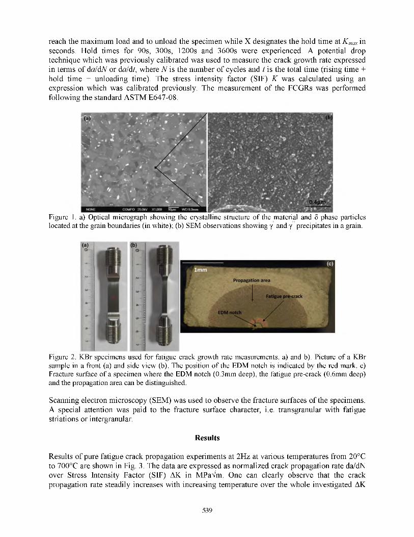
The chemical composition of the material is, in weight%: M 54.i8Cri7.97Fei7.3i(Nb+Ta)5.4M o2 97TuA l0.56Co0.14M n0.08Cu0.03C0.023B0.0041. This heat of Inco 718 alloy was received as a forged disk. It was given a conventional heat-treatment (720 °C - 8 h + 620 °C - 8 h) directly after forging (DA). More details on the development of Inco 718 DA can be found in [22]. Inco 718 DA exhibits y FCC matrix grains with a small grain size (5 to 15 |im). As shown in Fig. 1a, particles of the stable phase 5 (Ni3Nb) are formed along the grain boundaries, whereas small strengthening y’ (Ni3TiAl) and y” (Ni3Nb) are precipitated inside the FCC matrix grain (Fig. 1b). Due to the presence of carbon and traces of nitrogen, this alloy is prone to the formation of carbides and nitrides, which may precipitate either at the grain boundaries or within the y matrix grains (not visible in Fig. 1a). Carbide size distribution in Inco 718 was given in [23].
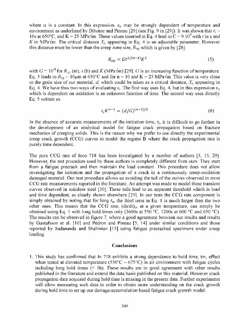
FCGR tests were performed from 500°C up to 675°C under an air environment using KBr specimens (Fig. 2a and 2b). The samples are 70mm long and the cross-sectional area of the gage section is 8.3 x 3.5 mm2. A small EDM semi-circular notch (depth 0.3mm) was introduced and the specimens were fatigue-precracked at room temperature (RT) and at a frequency of 10 Hz in order to extend the notch over a distance by about 0.3mm using a K-decreasing signal (Fig. 2c). In this way the crack propagation tests start with a long crack with regards to the microstructure of the material, away from the area affected by the EDM process and with a reduced plastic zone ahead of the crack type. Then the specimens were heated up and tested at R ratio of 0.05 where R = K min /K max. It is important to mention that all crack growth tests were performed under constant applied load, i.e. K increasing conditions. The tests were performed either under continuous pure fatigue (PF) at 2 Hz or with a trapezoidal shape signal 10/X/10 where 10 is the time (in s) to
538
reach the maximum load and to unload the specimen while X designates the hold time at K max in seconds. Hold times for 90s, 300s, 1200s and 3600s were experienced. A potential drop technique which was previously calibrated was used to measure the crack growth rate expressed in terms of da/dN or da/dt, where N is the number of cycles and t is the total time (rising time + hold time + unloading time). The stress intensity factor (SIF) K was calculated using an expression which was calibrated previously. The measurement of the FCGRs was performed following the standard ASTM E647-08.
Figure 1. a) Optical micrograph showing the crystalline structure of the material and S phase particles located at the grain boundaries (in white); (b) SEM observations showing y and y precipitates in a grain.
Figure 2. KBr specimens used for fatigue crack growth rate measurements. a) and b). Picture of a KBr sample in a front (a) and side view (b). The position of the EDM notch is indicated by the red mark. c) Fracture surface of a specimen where the EDM notch (0.3mm deep), the fatigue pre-crack (0.6mm deep) and the propagation area can be distinguished.
Scanning electron microscopy (SEM) was used to observe the fracture surfaces of the specimens. A special attention was paid to the fracture surface character, i.e. transgranular with fatigue striations or intergranular.
Results
Results of pure fatigue crack propagation experiments at 2Hz at various temperatures from 20°C to 700°C are shown in Fig. 3. The data are expressed as normalized crack propagation rate da/dN over Stress Intensity Factor (SIF) AK in MPaVm. One can clearly observe that the crack propagation rate steadily increases with increasing temperature over the whole investigated AK
539

domain. The effect is attributed to the decrease of the static mechanical properties of the material, especially the Young modulus and the yield strength. The crack propagation experiments were performed such that the initial value of AK is high enough to avoid any threshold effects on the measured crack propagation rate.
• • • . A
>•A
A
_____ k . ►
X*1 j A i '*
*
♦♦♦*♦ 20°C -fa tig u e 2Hz
4 5 0 ° C -fa tig u e 2Hz
a 5 5 0 ° C -fa tig u e 2Hz
• 6 5 0 ° C -fa tig u e 2Hz
x 7 0 0 ° C -fa tig u e 2Hz
♦
delta K (MPaVm)10 100
Figure 3. Fatigue crack propagation curves between 20°C and 700°C at 2Hz represented in the diagram delta K (MPaVm) over a normalized crack propagation rate da/dN obtained using the following experimental conditions: 20°C (dark blue diamonds), 450°C (light blue squares), 550°C (orange triangles), 650°C (red disks) and 700°C (purple crosses).
However it can be observed that the first points acquired at 700°C do not fit with the following points which form a line in the log-log diagram. This can be explained by the fact that the fatigue long crack propagation threshold, which is around 5 MPaVm at room temperature, increases with increasing temperature. In addition, the applied load at 700°C must be rather low compared to lower temperature to account for the sharp decrease of the yield strength of the material above 650°C, giving a low initial AK. It has to be pointed out that only the results of crack propagation experiments performed with R-ratio of 0.05 are shown in figure 3. The crack propagation behavior of the material was also investigated at other R-ratio ranging from -1 to 1 in order to characterize the crack closure effect from 20°C et 700°C. However those results which are out of the scope of this study are not presented here.
Figure 4 shows results of hold time crack propagation experiments with hold times ranging from 90s to 3600s at 550°C (Fig. 4a) and 650°C (Fig. 4b). Data is expressed as normalized crack propagation rate da/dN over AK in MPaVm. For each temperature, the pure fatigue crack propagation curve at 2Hz in represented in order to quantify the hold time effect on the crack propagation. For both temperatures, the hold time effect is clearly observed, as shown by the steady increase of the crack propagation rate da/dN with increasing hold time.
At 550°C (Fig. 4a), the crack growth rate is already affected by a hold time of 90s since the crack propagation rate is about twice faster than the pure fatigue crack growth rate. The effect is emphasized with increasing hold time, up to about two decades when experiments with 1h hold time are performed. It can be pointed out that the slope of the crack propagation curves obtained from hold time experiments are close to the slope of the pure fatigue crack growth curve at 550°C. At 650°C (Fig. 4b), the hold time effect is more pronounced compared to 550°C.
540

Figure 4. Crack propagation curves at 550°C (a) and 650°C (b) represented in the diagram delta K (MPaVm) over a normalized crack propagation rate da/dN obtained using the following experimental conditions: pure fatigue cycling at 2Hz (magenta crosses), 1.5/90/1.5 (dark blue triangles), 10/300/10 (light blue squares), 10/1200/10 (orange diamonds) and 10/3600/10 (red disks).
For a hold time of 300s, the crack propagation rate at 650°C is about two decades faster than at 550°C, whereas only one decade is observed between the crack propagation rate of 300s hold time tests compared to fatigue at 2Hz. This indicates that an increase of the temperature worsens the hold time effect on the crack propagation rate. This point will be discussed later. Inversely to what is observed at 550°C, the slope of the crack propagation curves obtained from hold time experiments is higher than the slope of the pure fatigue crack growth curve. Finally, it can be mentioned that the longer tests ran for two to three weeks at temperatures up to 650°C. Based on internal studies, it was shown that no decrease of the mechanical properties of Inco 718 DA occurred after annealing for thousands of hours at this level of temperature.
As already mentioned, the data presented in figure 4 indicated that a hold time of 90s at 550°C is sufficient to induce an acceleration of the cyclic crack growth rate. In this study, crack growth tests at higher temperatures with shorter hold times were not performed. Similarly, the effect of much longer hold times was not investigated. These tests could show a possible saturation of the hold time effect at 550°C. Gustafsson et al. performed crack growth experiments with hold times up to 6h on a solution heat-treated Inco 718. These authors did not observe a saturation of the hold time effect at 550°C [10].
541

The results of FCGR measurements, da/dN expressed as normalized values, are shown in figure 5 as a function of the test frequency f (Hz) for given values of AK: 35 MPaVm in figure 5a, 25 MPaVm in figure 5b and 15 MPaVm in figure 5c. In each graph, data points from pure fatigue (2Hz) and hold time crack growth experiments performed at 500°C (light blue squares), 550°C (red diamonds), 600°C (green triangles), 650°C (dark blue disks) and 675°C (magenta crosses) are represented. In addition, the experimental domains of trans- and intergranular crack propagation modes are indicated while the transition between those domains based on the presented results is represented by pink squares. This transition also observed by Pedron on solution heat-treated Inco 718 at 40 MPaVm (grain size of 50^m) is represented by the orange squares [14]. Regimes A and B refer to the transition domain between trans- and intergranular propagation and the intergranular purely time dependent crack propagation domain and are indicated in figure 5a, b and c. The characteristics of those regimes will be discussed in the discussion part. Finally, it has to be mentioned that the colored horizontal solid lines in the trans- granular regime and the colored dot lines in regime A and B are not fitted curves but only guides for the eyes. The slopes are indicated on each diagram.The dispersion of the results will not be discussed here. Possible explanations are, among others, the experimental procedures, as well as the dispersion in the grain size of the material or in the residual grain orientation after forging.
In figure 5 (a, b and c), it is assumed that the crack propagation rate in the domain of high frequencies, where trans-granular crack propagation occurs, is independent on the frequency and only increases with increasing temperature and AK (see figure 4).This is represented by solid horizontal lines in the graphs which indicates that the fatigue crack propagation is not influenced by environmental effects and is only driven by crack tip blunting as shown in [3]. In this domain, the horizontal lines are drawn longer towards lower frequencies for lower temperatures. This representation indicates that the transition between trans- and intergranular crack propagation is shifted towards higher frequencies as the temperature increases.
At the opposite in the domain of low frequencies (i.e. long hold times), one can observe that the crack propagation rate is time dependent, which strongly indicates the influence of environment. However one can observe different behaviors as a function of temperature and AK. At AK of 35 (Fig. 5a) and 25 MPaVm (Fig. 5b) above 550°C, the crack propagation rate increases linearly (in a log-log diagram) with decreasing frequencies. This is indicated by a slope of 1 in the graphs. Therefore the crack propagation rate here depends solely on the hold time applied during high temperature cycling, here referred to as regime B where crack propagation occurs along the grain boundaries. One can distinguish another behavior for the same two levels of AK at 500°C since the increase of the crack propagation rate is not purely time dependent, as represented by the slope of about 2/3 on the graphs. This behavior suggests that the crack propagation is not only driven by the hold time at 500°C at the frequencies tested in this study. The crack propagation is rather in a transition domain, which is noted as regime A in this paper, where mixed trans- and intergranular propagation can be observed. Further experiments at 500°C with lower frequencies would be necessary to investigate if regime B can be reached at 500°C. As already mentioned, the pink squares represent the transition between trans- and intergranular propagation based on the presented results. It can be noted that this transition seems to be relatively independent on the level of AK, as least for high values of AK. However further experiments will be needed to confirm this suggestion, especially with hold times lower than 90s. The transition between trans- and intergranular propagation from Pedron is added in figure 5a for comparison [14]. It clearly appears that the transition based on the results presented here is shifted towards lower frequencies. Based on the fact that the crack propagation rate is higher in regime B than in the
542

trans-granular propagation mode, it demonstrates that the Inco 718 DA tested here exhibits better crack propagation properties compared to the conventional material tested by Pedron.
Figure 5. Crack propagation results represented in the diagram f (Hz) over a normalized crack propagation rate da/dN from 500°C to 675°C. The results are obtained after pure fatigue (2 Hz) and hold time crack growth tests with tm from 90s (~1E-2 Hz) to 3600s (~2.7E-4 Hz) for AK=35MPaVm (a), AK=25MPaw (b) and AK=15MPaVm (c). The pink squares represent the transition between the trans- and inter-granular crack propagation domain based on our results in figures 7a and 7b. Orange squares represent the same transition based on Pedron’s results in figure 7c (at 40MPaVm, Ref. 14).
543

The crack propagation behaviors observed at 15 MPaVm (Fig 5c) as a function of the test temperature are more complicated to analyze and will need further experiments to be clarified. At 650°C (no data could be acquired at 675°C and 15 MPaVm), the crack propagation is purely time dependent, as already observed in figures 5a and b for this temperature. However, this is not observed at 600°C and 550°C where a slope of about 2/3 describes the evolution of the crack propagation rate with frequency. Therefore inversely to what was observed at higher AK values, it suggests that the crack propagation at those temperatures for a low value of AK occurs following regime A. This is more pronounced at 500°C since a slope of about 0.5 describes the evolution of the crack propagation rate as a function of the frequency.
In conclusion, the transition between the pure trans-granular crack propagation mode and regime B cannot be accounted as a single line but rather as a domain, where both trans- and intergranular crack propagation occurs (regime A). This domain seems to be dependent on the temperature, frequency and level of AK. Hence crack propagation in regime B only occurs above 650°C for low level of AK while at lower temperatures, crack propagation in regime A takes place. This description can also be proposed for the crack propagation at higher values of AK. However crack propagation in regime A only occurs at 500°C whereas crack propagation at higher temperature is characteristic of regime B crack propagation.
The previous explanations concerning the FCGR behavior are supported by SEM analyses of crack front surfaces after crack propagation tests in various conditions (Fig. 6). Numbers in figure 6b and d were used to measure the inter-striations spacing. Figure 6a and b shows SEM observations of fracture surface after a fatigue crack propagation test with 2Hz at 550°C. One can clearly observe that the fracture mode is purely transgranular (Fig. 6a) with the presence of fatigue striations (Fig. 6b). This mechanism is observed for tests performed in pure fatigue from 20°C to 675°C. In the regime B, the fracture mode is purely intergranular, as shown in figures 6e and f for a test performed at 650 °C with hold time cycle of 10/1200/10. It is reminded that regime B corresponds to the experimental domain where the crack propagation rate da/dN is purely time dependent.
Figure 6. SEM observations of fracture surfaces. a) and b) 550 °C in pure fatigue cycling at 2 Hz (pure trans-granular crack propagation); c) and d) 500 °C with hold time cycle of 10/300/10 at 30MPaVm. (mixed trans- and inter-granular propagation; e) and f) 650 °C with hold time cycle of 10/1200/10 (pure inter-granular crack propagation).
544

As shown in figure 5, the regime B is observed for temperatures above 500°C and AK above 15MPaVm.In the regime A, which refers to the transition domain between trans- and intergranular propagation, the fracture surface is also predominantly intergranular, although less brittle than that observed in regime B. In this particular condition as shown in figure 6c and d for a test performed at 500°C and with hold time cycle of 10/1200/10, the fracture mode is mixed, with areas showing features of intergranular and transgranular fracture. As shown in figure 5, the regime A is observed at 500°C between AK level of 35MPaVm and 25MPaVm, and below 600°C at 15MPaVm.
The creep crack growth (CCG) rate, which can be here understood as the crack growth rate measured in regime B (high temperature, large AK, and low frequency), is represented in figure7. The CCG rate da/dt expressed as normalized values is plotted versus K (MPaVm). The solid lines represent the mean creep crack propagation rate between 550°C and 650°C obtained from results presented in this study and the dispersion of the data is indicated. Our data is compared to the results obtained by Gustafsson et al. [10] and Pedron and Pineau [5, 14] under similar conditions and those reported by Sadananda and Shahinian [15] using fatigue precracked specimens under creep loading. A good agreement between both sets of results is observed which suggests that crack propagation in regime B is not too much dependent on microstructural details. The results obtained by Sadananda and Shahinian [15] are also included in figure 7 but, as these authors have investigated the propagation of a fatigue precrack under constant load, the results obtained by Sadananda and Shahinian and corresponding to the “steady” state regime only are included in figure 7 to avoid the transient regime. Their results are also close to ours and to those of Gustafsson et al. [10], reinforcing our hypothesis on the moderate effect of microstructure in this regime of crack propagation. Finally, one can observe that the slope of the (da/dt)cr curves drawn in figure 7 is between 2 and 4.
Figure 7. Crack growth propagation test results represented in a diagram K in MPaVm over a normalized da/dt corresponding to regime B (purely time dependant with intergranular crack propagation). The solid lines represent the mean creep crack propagation rate between 550°C and 650°C obtained from results presented in this study and the dispersion of the data is represented. Results by Gustafsson et al. (diamonds) [10], Pedron and Pineau (triangles) [5, 14] and Sadananda and Shahinian (circles) [15] are shown.
545

Discussion
This study has largely confirmed that Inco 718 alloy is very sensitive to hold time effect when tested with a trapezoidal wave shape signal at elevated temperature (> 550°C). The experimental results have shown that this hold time effect can be decomposed into two regimes, named A andB. In regime A, the fatigue crack growth rate at a given AK varies with ( tm) a where a < 1. This is a transition regime not discussed here but elsewhere [16] before the appearance of regime B which is purely time-dependent, i.e. in which a = 1. This regime B occurs at higher frequency when the test temperature is increased (see Fig. 5a, b and c). The transition between the “pure” fatigue regime corresponding to higher frequencies and time dependent regimes A and B is associated with a modification in fracture mode from transgranular to intergranular. This transition does not seem to change too much with the value of AK (compare Fig. 5a and b). A close examination to figure 5a indicates that this transition occurs in our DA material at a smaller frequency as compared to a conventionally heat treated 718 alloy with a larger grain size [5].
Further experiments showing the influence of environment and thermo-mechanical loading on the FCGR behavior of Inco 718
Other studies [5, 19] have shown that oxidation is responsible for this hold time or frequency effect, as indicated previously. A recent study by Viskari et al [19] on an alloy (Inco 718+) close to Inco 718 and using the most sophisticated techniques such as atom probe tomography has shown that oxygen enrichment occurred over 20nm below the protective chromium-rich oxide and that oxygen diffusion into the matrix was enhanced by crystallographic defects.
Many studies devoted to the interaction between oxidation and mechanical loading have also shown that oxygen has an effect only on in the presence of a significant visco-plastic strain [2426]. This means that, as indicated in the introduction and demonstrated in [18], the most severe part of a hold time corresponds to the start of stress relaxation. In the presence of a partial unloading which limits the stress relaxation ahead of the crack tip, the hold time effect can be largely reduced. This is shown in figure 8 [24, 25]. A strong effect of partial unloading is observed, especially at low K peak (not shown here) where only those corresponding to K peak = 30MPaVm are reported. Figure 8 shows that the fatigue crack growth rate can be reduced by almost two orders of magnitude when the unloading ratio is larger than 0.20. This effect of partial unloading was also shown in other Ni-base superalloys, such as N18 [24] and Astroloy[27].
Another way of reducing tensile stresses ahead of the crack tip in a component under constant overall loading is to rapidly increase the temperature for a certain time, t, and to intermittently repeat the process. This possibility was also explored in Inco 718 [24, 25]. The applied temperature-load time cycle is shown in figure 9a where a short increase in temperature (TMax - TBase Line) is imposed just at the start of the 300s hold time for only 30s. The base line temperature was maintained at 650°C while TMax was fixed at 675°C. Figure 9b shows that this anisothermal cycle generates a significant decrease of the crack growth rate, especially at low K values where the short temperature excursion produces sufficiently large effects to annihilate the hold time effect observed under purely isothermal conditions at 650°C.
Introduction
546

Unloading from peak (%)
Figure 8. Results on alloy Inco 718 tested at 650°C showing the reduction in crack propagation rate produced by the application of a hold time after a peak load [24].
AK (M l’ u n W )
Figure 9. Application of a temperature excursion during a fatigue cycle with a tensile hold time. (a) Sketch showing the temperature/load-time cycle. (b) Results obtained on Inco 718 with a base line temperature of 650°C and a maximum temperature of 675°C [24].
Fractographic observations indicated that the fracture mode under these anisothermal conditions was predominantly transgranular as observed in continuous fatigue (i.e. no hold time). Further experiments in which the temperature excursion was larger (650-700°C) showed that the fatigue crack growth rates were not reduced as compared to those measured under purely isothermal conditions at 650°C. This suggests that under these conditions the detrimental oxidation effect largely dominates the beneficial effect of crack tip stress relaxation. Further details can be found in [24]. The above experiments in which either the load is decreased during the hold time or the temperature is slightly increased clearly demonstrate that, in the presence of a strong interaction between oxidation and viscoplasticity, purely isothermal tests are not sufficient to assess the crack growth rate resistance of the Ni-base superalloys, such as Inco 718. It is certainly possible that the operating conditions in a jet engine mimic, to some degree, the test condition just described thereby producing large reduction in propagation rate and giving an added measure of durability and safety to the engines.
547

Modeling hold time effect on fatigue crack growth rates of In 718 at elevated temperature
In the absence of a detailed analysis of the local crack tip stress-strain field and a better knowledge of the micro-mechanisms of damage due to oxygen, only simple models can be proposed. A simple model based on a linear summation of three components is proposed to describe the crack propagation during hold time loading, i.e.:
The three components in Eq. 1 are successively analyzed in more detail. (da/dN)PF represents the “pure fatigue” (PF) components. This contribution to FCGR which is temperature dependent but not environment dependent has already been discussed by Clavel and Pineau [2, 3]. A simple Paris law, modified by Elber’s formula which describes the closure effect, is used to ascribe the fatigue contribution to the CGR:
(dN)pp = C(AKeff)m w ith AKeff = (aR + b)AK (2)
with C and m the Paris coefficients, AKeff the effective SIF, a and b the Elber coefficients and R the R-ratio. Although experimental details are not given there, it has to be mentioned that the pure FCGR contribution is validated on a database including tests from 20°C to 675°C for R-ratio ranging from -0.5 to 0.5 and over a AK domain from 10 to 90 MPaVm.
The second term in Eq. 1 represents the « oxidation » (OX) component. It is assumed that no crack propagation takes place during the hold time, tm, provided that tm < ti. However oxidation occurs at the crack type and produces a damaged zone which might correspond to the area evidenced by Gustafsson et al. [12, 13]. These authors showed that the extent of this area was proportional to ( tm) a where a ~ 0.25. One attempt has been made to relate this exponent a Q to the calculated concentration in oxygen along the grain boundaries [16]. However in the absence of values for the diffusivity of oxygen, through the matrix and the grain boundaries, it has been difficult to conclude unambiguously about the quantitative analysis of intergranular damage due to oxidation in regime A.
The acceleration in FCGR in the purely time dependent domain (regime B) might be simply related to creep damage which is oxidation dependent. Riedel and Rice [28] have shown that the viscoplastic strain in creeping solids with a Norton type law can be written as:
£ = F t 1/(n+1)( ^ / V r ) 2n/(n+1) (3)
In this expression F is a numerical factor which is an increasing function of temperature. This factor is equal to 8.34.10-9 at 650°C for plane strain conditions [29]. In Eq. 3, t is in h, K in MPaVm, r in m, n is the exponent of the stationary creep law. In our material it was found that n ~ 13 at 600°C and n ~ 6 at 650°C. In a previous study, it is assumed that n ~ 10 at 650°C [29]. Assuming that crack initiation takes place during the hold time, when a critical strain sc is reached over a characteristic distance Xc, Eq. 3 predicts that:
K 2nt i = P(ec )^+1(Xc)" = C (4)
548
where a is a constant. In this expression, sc may be strongly dependent of temperature and environment as underlined by Diboine and Pineau [29] (see Fig. 9 in [29]). It was shown that t i ~ 10s at 650°C, and K = 25 MPaVm. These values inserted in Eq. 4 lead to C ~ 9.109 with t in s and K in MPaVm. The critical distance X c appearing in Eq. 4 is an adjustable parameter. However this distance must be lower than the creep zone size, R vp which is given by [28]:
Rvp = Gt2/(n-1)K 2 (5)
with G = 10-8 for R vp (m), t (h) and K (MPaVm) [29]. G is an increasing function of temperature. Eq. 5 leads to Rvp ~ 10^m at 650°C and for n = 10 and K = 25 MPaVm. This value is very close to the grain size of our material, d, which could be taken as a critical distance, Xc appearing in Eq. 4. We have thus two ways of evaluating ti. The first way uses Eq. 4, but in this expression sc which is dependent on oxidation is an unknown function of time. The second way uses directly Eq. 5 written as:
t iKn~1 = (d /G ) (n-1)/2 (6)
In the absence of accurate measurements of the initiation time, ti, it is difficult to go further in the development of an analytical model for fatigue crack propagation based on fracture mechanics of creeping solids. This is the reason why we prefer to use directly the experimental creep crack growth (CCG) curves to model the regime B where the crack propagation rate is purely time dependent.
The pure CCG rate of Inco 718 has been investigated by a number of authors [5, 15, 29]. However, the test procedure used by these authors is completely different from ours. They start from a fatigue precrack and then maintain the load constant. This procedure does not allow investigating the initiation and the propagation of a crack in a continuously creep-oxidation damaged material. Our test procedure allows us avoiding the tail of the curves observed in most CCG rate measurements reported in the literature. An attempt was made to model these transient curves observed in stainless steel [30]. These tails lead to an apparent threshold which is load and time dependent, as clearly shown elsewhere [29]. In our tests the CCG rate component is simply obtained by noting that for long tm the third term in Eq. 1 is much larger than the two other ones. This means that the CCG rate, (da/dt)cr at a given temperature, can simply be obtained using Eq. 1 with long hold times only (3600s at 550 °C, 1200s at 600 °C and 650 °C). The results can be observed in figure 7, where a good agreement between our results and results by Gustafsson et al. [10] and Pedron and Pineau [5, 14] under similar conditions and those reported by Sadananda and Shahinian [15] using fatigue precracked specimens under creep loading.
Conclusions
1. This study has confirmed that In 718 exhibits a strong dependence to hold time, tm, effect when tested at elevated temperature (550°C - 675°C) in air environment with fatigue cycles including long hold times (< 1h). These results are in good agreement with other results published in the literature and extend the data basis published on this material. However crack propagation data acquired during hold time is missing in the present data. Further experiments will allow measuring such data in order to obtain more understanding on the crack growth during hold time to set up our damage-accumulation based fatigue crack growth model.
549

2. Using other results published in the literature it is shown that the hold time dependence is related to a combination of creep strain accumulation (occurring essentially at the onset of stress relaxation) and detrimental effect of oxidation.
3. Two regimes (A and B) have been defined when there is an acceleration of crack propagation rate in the presence of a hold time. Regime A corresponds to an acceleration as ( t m) a where a < 1, while regime B is purely time dependent (a = 1). In both cases the fracture mode becomes intergranular. The transition between the pure fatigue regime (high frequency) and the intergranular regime occurs at increasing frequency with increasing test temperature.
4. A simple linear damage accumulation law has been proposed to account for hold time effect. This law includes three terms: (i) a pure fatigue component, (ii) an oxidation component (regime A) and (iii) a pure creep component (regime B).
5. The creep component gives rise to a crack growth rate proportional to hold time, tm. This component is the most important at increasing temperature and hold time. It has been shown that the crack growth rate in regime B is an increasing function of hold time and temperature with apparent activation energy close to 300KJ/mole which might correspond to the activation energy for oxygen diffusion along the grain boundaries.
References
[1] D. Fournier, A. Pineau, Low cycle fatigue behavior of Inconel 718 at 298K and 823K, Met. Trans. 8A, 1977, pp. 1095-1105.
[2] M. Clavel, A. Pineau, Frequency and waveform effects on the fatigue crack growth behaviorof alloy 718 at 298K and 823K, Met. Trans. 9A, 1978, pp. 471-480.
[3] M. Clavel, A. Pineau, Fatigue behaviour of two nickel-base alloys I: Experimental results on low cycle fatigue, fatigue crack propagation and substructure, Mat. Sci. Eng. 25, 1982, pp. 157-171; II: Physical modeling of the fatigue crack propagation process, Mat. Sci. Eng. 25, 1982, pp. 173-180.
[4] L.A. James, W.J. Mills, Effect of heat treatment and heat-to-heat variations in the fatigue crack growth response of alloy 718, Engng. Fract. Mech. 22, 1985, pp. 797-817.
[5] J.P. Pedron, A. Pineau, The effect of microstructure and environment on the crack growth behaviour of Inconel 718 alloy at 650°C under fatigue, creep and combined loading, Mat. Sci. Eng. 56, 1982, pp. 143-156.
[6] J.E. King, Fatigue crack propagation in nickel-base superalloys - Effects of microstructure, load ratio and temperature, Mat. Sci. Eng. 3, 1987, pp. 750-764.
[7] H.H. Smith, D.J. Michel, Effect of environment on fatigue crack propagation behavior ofalloy 718 at elevated temperature, Met. Trans. 17A, 1986, pp. 370-374.
[8] M.R. Bache, W.J. Evans, M.C. Hardy, The effects of environment and loading waveform onfatigue crack growth in Inconel 718, Int. J. Fatigue, 21, 1999, pp. S69-S77.
[9] G.A. Osinkulu, G. Onofrio, M. Marchionni, Fatigue crack growth in polycrystalline IN 718 superalloy, Mat. Sci. Eng., A 356, 2003, pp. 425-433.
[10] D. Gustafsson, J.J. Moverare, S. Johansson, K. Simonsson, M. Hornqvist, T. Mansson, S. Sjostrom, Influence of high temperature hold times on the fatigue crack propagation in Inconel 718, Int. J. Fatigue, 33, 2011, pp. 1461-1469.
[11] M. Hornqvist, T. Mansson, D. Gustafsson, High temperature fatigue crack growth in Alloy 718 - Effect of tensile hold times, Proc. Eng., 10, 2011, pp. 147-152.
[12] D. Gustafsson, J. Moverare, K. Simonsson, S. Johansson, M. Hornqvist, T. Mansson, S. Sjostrom, Fatigue crack growth behaviour of Inconel 718 - The concept of a damaged zone caused by high temperature hold times, Proc. Eng., 10, 2011, pp. 2821-2826.
550

[13] S. Floreen, The creep fracture of wrought nickel-base alloys by a fracture mechanics approach, Met. Trans. 6A, 1975, pp. 1741-1749.
[14] J.P. Pedron, A. Pineau, Influence de l’oxydation sur la propagation des fissures a haute temperature dans l’alliage Inconel 718, Memoires et Etudes Scientifiques Revue de Metallurgie, 1983, pp. 665-674.
[15] K. Sadananda, P. Shahinian, Creep crack growth in Alloy 718, Met. Trans. 8A, 1977, pp. 439-449.
[16] A. Pineau, R. De Moura Pinho, S. Pierret, C. Mary, A Local Approach to Creep-Fatigue - Oxidation Interactions in Inco 718 Alloy, ICF13 Proceedings, 2013.
[17] H. Ghonem, D. Zheng, Depth of intergranular oxygen diffusion during environment- dependent fatigue crack growth in alloy 718, Mater. Sci. Eng., A150, 1992, pp. 151-160.
[18] R. Molins, G. Hochstetter, J.C. Chassaigne, E. Andrieu, Oxidation effects on the fatigue crack growth behaviour of Alloy 718 at high temperature, Acta Mater., 45, 1997, pp. 663674.
[19] L. Viskari, M. Hornqvist, K.L. Moore, Y. Cao, K. Stiller, Intergranualar crack tip oxidation in a Ni-base superalloy, Acta Mater., 61, 2013, pp. 3630-3639.
[20] A. Devaux, Propagation des fissures par fatigue a haute temperature dans l’Inconel 718 : Effets de microstructure et de chargements complexes, PhD Thesis, Ecole des Mines de Paris, 2011.
[21] A. Pineau, S.D. Antolovich, High temperature fatigue of nickel-base superalloys: A review with special emphasis on deformation modes and oxidation, EFA 16, 2009, 2668-2697
[22] D.D. Kruger, The development of direct aged 718 for gas turbine engine disk applications. Superalloys. TMS, 1989, pp 279-296.
[23] S. Deyber, F. Alexandre, J. Vaissaud, A. Pineau, Probabilistic life of DA718 for aircraft engine disks. Superalloys. TMS, 2005.
[24] S. Ponnelle. Propagation des fissures par fatigue a haute temperature dans l’Inconel 718 : effets de microstructure et de chargements complexes, PhD thesis, Ecole des Mines de Paris ; 2001.
[25] S. Ponnelle, B. Brethes, A. Pineau. High temperature fatigue crack growth rate in Inconel 718 : dwell effect annihilation. In: 9th International spring meeting, SF2M, temperature- fatigue interaction, Paris, May, 29-31; 2001.
[26] S. Ponnelle, B. Brethes, A. Pineau. Orientation effects and influence of delta phase on fatigue crack growth rates in a forged disc of Inconel 718 superalloy. In: 5th international special emphasis on superalloys 718, 625, 706 and derivatives, Pittsburg, PA, June, 17-20; 2001.
[27] S. Kruch, P. Prigent, J.L. Chaboche. A fracture mechanics based fatigue-creep-environment crack growth model for high temperature. Int. J. Press. Vessels Piping, 1994; 59, pp. 141148.
[28] H. Riedel, Fracture at high temperatures, MRE, Springer-Verlag, Berlin, Heidelberg, New York, 1987.
[29] A. Diboine, A. Pineau, Creep crack initiation and growth in Inconel 718 alloy at 650°C, Fatigue Fract. Engng. Mater. Struct., 10, 1987, pp. 141-151.
[30] E. Maas, A. Pineau, Creep crack growth behaviour of type 316L steel, Eng. Fracture Mechanics, 22, 1985, pp. 305-325.
[31] D.A. Woodford, Gas phase embrittlement and time dependent cracking of nickel based superalloys, Energy Materials 1, 2006, pp. 59-79.
[32] J. Charpigny, Fissuration sous fluage dans l’Inconel 718, PhD Thesis, Ecole des Mines de Paris, 1981.
551