hoists section i. chains and hooks
TRANSCRIPT

FM 5-125
C H A P T E R 3
H o i s t s
Section I. Chains and Hooks
Chains are much more resistant to abrasion In lifting, chains, as well as fiber ropesand corrosion than wire rope; use them or wire ropes, can be tied to the load. Butwhere this type of deterioration is a problem, for speed and convenience, it is muchas in marine work where anchor gear must better to fasten a hook to the end of thewithstand the corrosive effects of seawater. lifting line. Also, you can use hooks areYou can also use chains to lift heavy objects in constructing blocks.with sharp edges that would cut wire.
CHAINS
Chains are made up of a series of links fas-tened through each other. Each link ismade of a rod of wire bent into an ovalshape and welded at one or two points. Theweld ordinarily causes a slight bulge on theside or end of the link (see Figure 3-1). Thechain size refers to the diameter, in inches,of the rod used to make the link. Chainsusually stretch under excessive loading sothat the individual links bend slightly.Bent links are a warning that the chain hasbeen overloaded and might fail suddenlyunder a load. Wire rope, on the other hand,fails a strand at a time, giving warningbefore complete failure occurs. If a chain isequipped with the proper hook, the hookshould start to fail first, indicating that thechain is overloaded.Several grades and types of chains areavailable.
Hoists 3-1

FM 5-125
STRENGTH OF CHAINSTo determine the SWC on a chain, apply aFS to the breaking strength. The SWC ordi-narily is assumed to be about one-sixth ofthe BS, giving a FS of 6. Table 3-1 lists SWCfor various chains. You can approximate theSWC of an open-link chain by using the fol-lowing rule of thumb:
SWC = 8D2
SWC = Safe working capacity, in tonsD = Smallest link thickness or least diam-eter measured in inches (see Figure 3-1,page 3-1)
Example: Using the rule of thumb, the SWC
of a chain with a link thickness of 3/4 inchis—
SWC = 8D2 = 8 (3/4)2 = 4.5 tons or9,000 pounds
The figures given assume that the load isapplied in a straight pull rather than by animpact. An impact load occurs when anobject is dropped suddenly for a distanceand stopped. The impact load in such acase is several times the weight of the load.
CARE OF CHAINSWhen hoisting heavy metal objects usingchains for slings, insert padding aroundthe sharp corners of the load to protect the
3-2 Hoists

FM 5-125
chain links from being cut. The padding Cut the smaller chain links with a boltmay be either planks or heavy fabric. Do cutter; cut large chain links with a hack-not permit chains to twist or kink when saw or an oxyacetylene torch. Inspect theunder strain. Never fasten chain links chain chains frequently, depending on thetogether with bolts or wire because such amount of use. Do not paint chains toconnections weaken the chain and limit prevent rusting because the paint willits SWC. Cut worn or damaged links out interfere with the action of the links.of the chain and replace them with a cold- Instead, apply a light coat of lubricant andshut link. Close the cold-shut link and weld store them in a dry and well-ventilatedit to equal the strength of the other links. place.
HOOKS
The two general types of hooks availableare the slip hook and the grab hook (seeFigure 3-2). Slip hooks are made so thatthe inside curve of the hook is an arc of acircle and may be used with wire rope.chains. or fiber rope. Chain links can slipthrough a slip hook so the loop formed inthe chain will tighten under a load. Grabhooks have an inside curve that is nearlyU-shaped so that the hook will slip over alink of chain edgeways but will not permitthe next link to slip through. Grab hookshave a more limited range of use than sliphooks. They are used on chains when theloop formed with the hook is not intended toclose up around the load.
STRENGTH OF HOOKSHooks usually fail by straightening. Anydeviation from the original inner arc indi-cates that the hook has been overloaded.Since you can easily detect evidence ofoverloading the hook. you should use ahook that is weaker than the chain towhich it is attached. With this system.hook distortion will occur before the chainis overloaded. Discard severely distorted.cracked. or badly worn hooks because theyare dangerous. Table 3-2. page 3-4. listsSWCs on hooks. Approximate the SWC ofa hook by using the following rule ofthumb:
SWC = D2
D = the diameter in inches of the hookwhere the inside of the hook starts itsarc (see Figure 3-3. page 3-5)
Thus. the SWC of a hook with a diameterof 1 1/4 inches is as follows:
SWC=D2=(1 1/4)2 16 tons or 3,125pounds
MOUSING OF HOOKSIn general. always “mouse” a hook as asafety measure to prevent slings or ropesfrom jumping off. To mouse a hook afterthe sling is on the hook. wrap the wire orheavy twine 8 or 10 turns around the twosides of the hook (see Figure 3-4. page 3-5).
Hoists 3-3

FM 5-125
Complete the process by winding several securely. Mousing also helps preventturns of the wire or twine around the straightening of the hook but does notsides of the mousing and tying the ends strengthen it materially.
INSPECTING CHAINS AND HOOKS
Inspect chains, including the hooks, at least and cracks, sharp nicks or cuts, worn sur-once a month; inspect those that are used faces, and distortions. Replace those thatfor heavy and continuous loading more fre- show any of these weaknesses. If severalquently. Give particular attention to the links are stretched or distorted, do not usesmall radius fillets at the neck of hooks for the chain; it probably was overloaded orany deviation from the original inner arc. hooked improperly, which weakened theExamine each link and hook for small dents entire chain.
3-4 Hoists

FM 5-125
Section II. SlingsThe term “sling” includes a wide variety ofdesigns. Slings may be made of fiber rope,wire rope, or chain.Fiber rope makes good slings because of itsflexibility, but it is more easily damaged bysharp edges on the material hoisted than arewire rope or chain slings. Fiber-rope slingsare used for lifting comparatively light loadsand for temporary jobs.Wire rope is widely used for slings because ithas a combination of strength and flexibility.Properly designed and appropriately fabri-cated wire-rope slings are the safest type ofslings. They do not wear away as do slings
made of fiber rope, nor do they lose theirstrength from exposure as rapidly. Theyalso are not susceptible to the “weakestlink” condition of chains caused by theuncertainty of the strengths of the welds.The appearance of broken wires clearlyindicates the fatigue of the metal and theend of the usefulness of the sling.Chain slings are used especially wheresharp edges of metal would cut wire rope orwhere very hot items are lifted, as in found-ries or blacksmith shops.Barrel slings can be made with fiber rope tohold barrels horizontally or vertically.
TYPES OF SLINGSThe sling for lifting a given load may be— ENDLESS SLINGS
An endless sling. The endless sling is made by splicing the
A single sling. ends of a piece of wire rope or fiber ropetogether or by inserting a cold-shut link in a
A combination sling (several single chain. Cold-shut links should be weldedslings used together). after insertion in the chain. These endless
Each type or combination has its particular slings are simple to handle and may be usedadvantages that must be considered when in several different ways to lift loads (seeselecting a sling for a given purpose. Figure 3-5, page 3-6).
Hoists 3-5

FM 5-125
Choker or Anchor HitchA common method of using an endless slingis to cast the sling under the load to be liftedand insert one loop through the other andover the hoisting hook. When the hoistinghook is raised, one side of the choker hitch isforced down against the load by the strainon the other side, forming a tight grip on theload.
Basket HitchWith this hitch, the endless sling is passedaround the object to be lifted and bothremaining loops are slipped over the hook.
Inverted Basket HitchThis hitch is very much like the simple bas-ket hitch except that the two parts of the sling going under the load are spread wideapart.
Toggle HitchThe toggle hitch is used only for specialapplications. It is actually a modification of
the inverted basket hitch except that theline passes around toggles fastened to theload rather than going around the loaditself.
SINGLE SLINGSA single sling can be made of wire rope, fiberrope, or chain. Each end of a single sling ismade into an eye or has an attached hook(see Figure 3-6). In some instances, theends of a wire rope are spliced into the eyesthat are around the thimbles, and one eye isfastened to a hook with a shackle. With thistype of single sling, you can remove theshackle and hook when desired. You canuse a single sling in several different waysfor hoisting (see Figure 3-6). It is advisableto have four single slings of wire rope avail-able at all times. These can be used singlyor in combination, as necessary.
Choker or Anchor HitchA choker or anchor hitch is a single slingthat is used for hoisting by passing one eye
3-6 Hoists

FM 5-125
through the other eye and over the hoistinghook. A choker hitch will tighten downagainst the load when a strain is placed onthe sling.
Basket Hitch
A basket hitch is a single sling that ispassed under the load with both endshooked over the hoisting hook.
Stone-Dog HitchA stone-dog hitch is single slings with twohooks that are used for lifting stone.
Double Anchor HitchThis hitch is used for hoisting drums orother cylindrical objects where it is neces-sary for the sling to tighten itself understrain and lift by friction against the sides ofthe cylinder.
COMBINATION SLINGSSingle slings can be combined into bridleslings, basket slings, and choker slings tolift virtually any type of load. Either twoor four single slings can be used in a givencombination. Where greater length isrequired, two of the single slings can be com-bined into a longer single sling. One of theproblems in lifting heavy loads is in fasten-ing the bottom of the sling legs to the load insuch a way that the load will not be dam-aged. Lifting eyes are fastened to manypieces of equipment at the time it is manu-factured. On large crates or boxes, the slinglegs may be passed under the object to forma gasket sling. A hook can be fastened to theeye on one end of each sling leg to permiteasier fastening on some loads. Where theload being lifted is heavy enough or awk-ward enough, a four-leg sling may berequired. If a still greater length of sling isrequired, two additional slings can be usedin conjunction with the four-leg sling to forma double basket.
Hoists 3-7

FM 5-125
PALLETS
A problem in hoisting and moving loads the job out of 2- by 8-inch timbers that are 6sometimes occurs when the items to be or 8 feet long and are nailed to three or fourlifted are packaged in small boxes and the heavy cross members, such as 4- by 8-inchindividual boxes are not crated. In this timbers. Several pallets should be made upcase, it is entirely too slow to pick up each so that one pallet can be loaded while thesmall box and move it separately. Pallets, pallet previously loaded is being hoisted. Asused in combination with slings, provide each pallet is unloaded, the next return tripan efficient method of handling such of the hoist takes the empty pallet back forloads. The pallets can be made up readily on loading.
SPREADERSOccasionally, it is necessary to hoist loads that of the load, the angle of the sling leg isare not protected sufficiently to prevent crush- changed so that crushing of the load is pre-ing by the sling legs. In such cases, spreaders vented. Changing the angle of the sling legmay be used with the slings (see Figure 3-7). may increase the stress in that portion ofSpreaders are short bars or pipes with eyes on the sling leg above the spreaders. The deter-each end. The sling leg passes through the eye mining factor in computing the safe liftingdown to its connection with the load. By set- capacity of the sling is the stress (or tension)ting spreaders in the sling legs above the top in the sling leg above the spreader.
3-8 Hoists

FM 5-125
STRESSESTables 3-3 through 3-5, pages 3-10through 3-12, list the SWCs of ropes,chains, and wire-rope slings under variousconditions. The angle of the legs of a slingmust be considered as well as the strength ofthe material of which a sling is made. Thelifting capacity of a sling is reduced as theangle of its legs to the horizontal is reduced(as the legs of a sling are spread) (see Figure3-7). Thus, reducing the angle of the legs ofa sling increases the tension on the slinglegs. In determining the proper size of sling,you must determine the tension on each legfor each load (see Figure 3-8, page 3-13).You can compute this tension using the fol-lowing formula:
T = Tension in a single sling leg (whichmay be more than the weight of the loadlifted)W= Weight of the load to be liftedN = Number of slingsL = Length of slingV = Vertical distance, measured from thehook to the top of the loadNOTES:
1. L and V must be expressed in thesame unit of measure.2. The resulting tension will be inthe same unit of measure as that ofthe weight of the load. Thus, if theweight of the load is in pounds, thetension will be given in pounds.
Example: Determine the tension of a singleleg of a two-legged sling being used to lift aload weighing 1,800 pounds. The length ofa sling is 8 feet and the vertical distance is 6feet.
Solution:
T=
T= 1,200 pounds or 6 tons
By knowing the amount of tension in a sin-gle leg, you can determine the appropriatesize of fiber rope, wire rope, or chain. TheSWC of a sling leg (keeping within thesafety factors for slings) must be equal to orgreater than the tension on a sling leg. Ifpossible, keep the tension on each sling legbelow that in the hoisting line to which thesling is attached. A particular angle formedby the sling legs with the horizontal wherethe tension within each sling leg equals theweight of the load is called the critical angle(see Figure 3-9, page 3-13). Approximatethis angle using the following formula:
Critical angle =
N = Number of sling legs
When using slings, stay above the criticalangle.
INSPECTING AND CUSHIONING SLINGSInspect slings periodically and condemn 4 percent or more of the wires are broken.them when they are no longer safe. Make Pad all objects to be lifted with wood blocks,the usual deterioration check for fiber ropes, heavy fabric, old rubber tires, or other cush-wire ropes, chains, and hooks when you use ioning material to protect the legs of slingsthem in slings. Besides the usual precautions, from being damaged.declare wire ropes used in slings unsafe if
Hoists 3-9

FM 5-125
3-10 Hoists

FM 5-125
Hoists 3-11

FM 5-125
3-12 Hoists

FM 5-125
Hoists 3-13

FM 5-125
Section III. Blocks and Tackle Systems
A force is a push or pull. The push or pullthat humans can exert depends on theirweight and strength. To move any loadheavier than the maximum amount a per-son can move, use a machine that multi-plies the force exerted into a force capable ofmoving the load. The machine may be alever, a screw, or a tackle system. The sameprinciple applies to all of them. If you use amachine that exerts a force 10 times greaterthan the force applied to it, the machine hasmultiplied the force input by 10. Themechanical advantage (MA) of a machine isthe amount by which the machine multi-plies the force applied to it to lift or move aload. For example, if a downward push of 10pounds on the left end of a lever will causethe right end of the lever to raise a loadweighing 100 pounds, the lever is said tohave a MA of 10.
A block consists of a wood or metal framecontaining one or more rotating pulleyscalled sheaves (see Figure 3-10, A). A tackleis an assembly of ropes and blocks used tomultiply forces (see Figure 3-10, B). Thenumber of times the force is multiplied isthe MA of the tackle. To make up a tacklesystem, lay out the blocks you are to use tobe used and reeve (thread) the rope throughthe blocks. Every tackle system contains afixed block attached to some solid supportand may have a traveling block attached tothe load. The single rope leaving the tacklesystem is called the fall line. The pullingforce is applied to the fall line, which maybe led through a leading block. This is anadditional block used to change the direc-tion of pull.
BLOCKSBlocks are used to reverse the direction ofthe rope in the tackle. Blocks take theirnames from—
The purpose for which they are used.
The places they occupy.
A particular shape or type of construc-tion (see Figure 3-11).
TYPES OF BLOCKSBlocks are designated as single, double, ortriple, depending on the number of sheaves.
Snatch BlockThis is a single sheave block made so thatthe shell opens on one side at the base of thehook to permit a rope to be slipped over thesheave without threading the end of itthrough the block. Snatch blocks ordinarily
are used where it is necessary to changethe direction of the pull on the line.
Traveling BlockA traveling block is attached to the loadthat is being lifted and moves as the load islifted.
Standing BlockThis block is fixed to a stationary object.
Leading BlocksBlocks used in the tackle to change thedirection of the pull without affecting theMA of the system are called leading blocks(see Figure 3-12, page 3-16). In some tacklesystems, the fall line leads off the last blockin a direction that makes it difficult toapply the motive force required. A leadingblock is used to correct this. Ordinarily, a
3-14 Hoists

FM 5-125
Hoists 3-15

FM 5-125
snatch block is used as the leading block.This block can be placed at any convenientposition. The fall line from the tackle sys-tem is led through the leading block to theline of most direct action. -
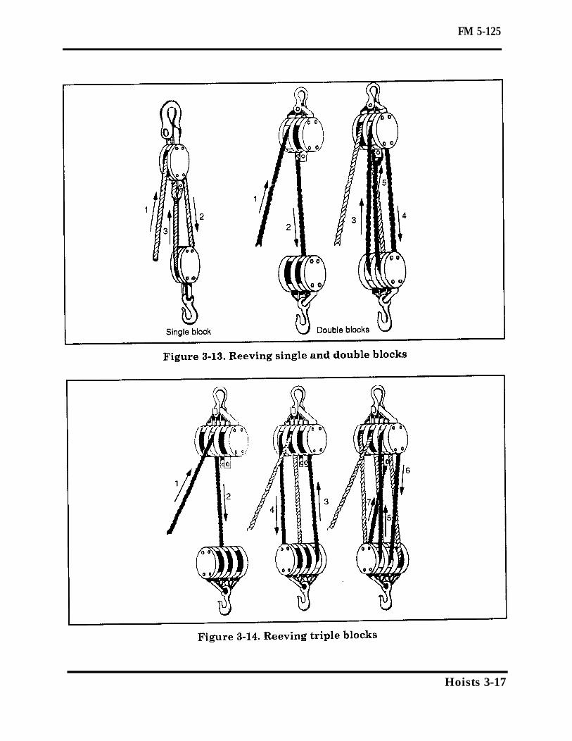
REEVING BLOCKSTo prepare blocks for use, reeve, or pass arope through, it. To do this, lay out theblocks on a clean and level surface otherthan the ground to avoid getting dirt intothe operating parts, Figure 3-13 shows thereeving of single and double blocks. In reev-ing triple blocks, it is imperative that youput the hoisting strain at the center of theblocks to prevent them from being inclinedunder the strain (see Figure 3-14). If theblocks do incline, the rope will drag acrossthe edges of the sheaves and the shell of theblock and cut the fibers. Place the blocks sothat the sheaves in one block are at rightangles to the sheaves in the other block.You may lay the coil of rope beside eitherblock. Pass the running end over the centersheave of one block and back to the bottomsheave of the other block. Then pass it overone of the side sheaves of the first block. Inselecting which side sheave to pass the rope
over, remember that the rope should notcross the rope leading away from the cen-ter sheave of the first block. Lead the ropeover the top sheave of the second blockand back to the remaining side sheave ofthe first block. From this point, lead therope to the center sheave of the secondblock and back to the becket of the firstblock. Reeve the rope through the blocksso that no part of the rope chafes anotherpart of the rope.
Twisting of BlocksReeve blocks so as to prevent twisting.After reeving the blocks, pull the rope backand forth through the blocks several timesto allow the rope to adjust to the blocks.This reduces the tendency of the tackle totwist under a load. When the ropes in atackle system become twisted, there is anincrease in friction and chafing of theropes, as well as a possibility of jammingthe blocks. When the hook of the standingblock is fastened to the supporting member,turn the hook so that the fall line leadsdirectly to the leading block or to the sourceof motive power. It is very difficult to pre-vent twisting of a traveling block. It is par-ticularly important when the tackle isbeing used for a long pull along the ground,such as in dragging logs or timbers.
Antiwisting DevicesOne of the simplest antitwisting devices forsuch a tackle is a short iron rod or apiece of pipe lashed to the traveling block(see Figure 3-15, page 3-18). You can lashthe antitwisting rod or pipe to the shell ofthe block with two or three turns of rope. Ifit is lashed to the becket of the block, youshould pass the rod or pipe between theropes without chafing them as the tackle ishauled in.
3-16 Hoists
FM 5-125
Hoists 3-17

FM 5-125
TACKLE
Tackle systems may be either simple or com-pound.
SIMPLE TACKLE SYSTEMSA simple tackle system uses one rope andone or more blocks. To determine the MA ofa simple system, count the number of linessupporting the load (or the travelingblock) (see Figure 3-16). In counting,include the fall line if it leads out of a travel-ing block. In a simple tackle system, the MAalways will be the same as the number oflines supporting the load. As an alternatemethod, you can determine the MA by trac-ing the forces through the system. Beginwith a unit force applied to the fall line.Assume that the tension in a single rope isthe same throughout and therefore the sameforce will exist in each line. Total all theforces acting on the load or traveling block.The ratio of the resulting total force actingon the load or traveling block to the originalunit force exerted on the fall line is the theo-retical MA of the simple system.Figure 3-17 shows examples of two meth-ods of determining the ratio of a simpletackle system. They are—
Method I-counting supporting lines.
Method II—unit force.
SYSTEMS
Method I—Counting Supporting LinesThere are three lines supporting the travel-ing block, so the theoretical MA is 3:1.
Method II—Unit ForceAssuming that the tension on a single ropeis the same throughout its length, a unitforce of 1 on the fall line results in a total of3 unit forces acting on the traveling block.The ratio of the resulting force of 8 on thetraveling block to the unit force of 1 on thefall line gives a theoretical MA of 3:1.
COMPOUND TACKLE SYSTEMSA compound tackle system uses more thanone rope with two or more blocks (see Figure3-18, page 3-20). Compound systems aremade up of two or more simple systems.The fall line from one simple system is fas-tened to a hook on the traveling block ofanother simple system, which may includeone or more blocks. In compound systems,you can best determine the MA by using theunit-force method. Begin by applying a unitforce to the fall line. Assume that the ten-sion in a single rope is the same throughoutand therefore the same force will exist ineach line. Total all the forces acting on the
3-18 Hoists

FM 5-125
Hoists 3-19

FM 5-125
traveling block and transfer this force intothe next simple system. The ratio of theresulting total force acting on the load ortraveling block to the original unit forceexerted on the fall line is the theoreticalMA of the compound system. Anothermethod, which is simpler but less accuratein some cases, is to determine the MA ofeach simple system in the compound systemand multiplying these together to obtain thetotal MA. Figure 3-19 shows examples of the
two methods of determining the ratio of acompound tackle system. They are—
Method I—unit force.
Method II—multiplying mechanicaladvantages of simple systems.
Method I—Unit ForceAs in method II of simple tackle systems, aunit force of 1 on the fall line results in 4unit forces acting on the traveling block oftackle system A. Transferring the unit forceof 4 into the fall line of simple system Bresults in a total of 16 unit forces (4 lineswith 4 units of force in each) acting on thetraveling block of tackle system B. The ratioof 16 unit forces on the traveling block carry-ing the load to a 1 unit force on the fall linegives a theoretical MA of 16:1.
Method II—Multiplying MAs ofSimple Systems
The number of lines supporting the travel-ing blocks in systems A and B is equal to 4.The MA of each simple system is thereforeequal to 4:1. You can then determine theMA of the compound system by multiplyingtogether the MA of each simple system for aresulting MA of 16:1.
FRICTIONThere is a loss in any tackle system becauseof the friction created by—
The sheave rolling on the pin, the ropesrubbing together.
The rope rubbing against the sheave.
This friction reduces the total lifting power;therefore, the force exerted on the fall linemust be increased by some amount to over-come the friction of the system to lift theload. Each sheave in the tackle system canbe expected to create a resistance equal toabout 10 percent of the weight of the load.
3-20 Hoists

FM 5-125
Hoists 3-21

FM 5-125
Example: A load weighing 5,000 pounds is MA of the tackle system. The actual pulllifted by a tackle system that has a MA of required on the fall line would be equal to4:1. The rope travels over four sheaves that the sum of 5,000 pounds (load) and 2,000produce a resistance of 40 percent of 5,000 pounds (friction) divided by 4 (MA) or 1,750pounds or 2,000 pounds (5,000 x 0.40). The pounds.actual pull that would be required on the fall There are other types of resistance thatline of the tackle system is equal to the sum may have to be considered in addition toof the weight of the load and the friction in tackle resistance. FM 20-22 presents athe tackle system divided by the theoretical. thorough discussion of resistance.
Section IV. Chain Hoists and WinchesIn all cases where manpower is used forhoisting, the system must be arranged toconsider the most satisfactory method ofusing that source of power. More men canpull on a single horizontal line along theground than on a single vertical line. On avertical pull, men of average weight canpull about 100 pounds per man and about60 pounds per man on a horizontal. Ifthe force required on the fall line is 300pounds or less, the fall line can leaddirectly down from the upper block of a
CHAIN
Chain hoists provide a convenient and effi-cient method for hoisting by hand underparticular circumstances (see Figure 3-20).The chief advantages of chain hoists arethat—
The load can remain stationary with-out requiring attention.
One person can operate the hoist toraise loads weighing several tons.
The slow lifting travel of a chain hoist per-mits small movements, accurate adjust-ments of height, and gentle handling ofloads. A retched-handle pull hoist is usedfor short horizontal pulls on heavy objects(see Figure 3-21). Chain hoists differ widelyin their MA, depending on their rated capac-ity which may vary from 5 to 250.
TYPES OF CHAIN HOISTSThe three general types of chain hoists for
tackle vertical line. If 300 pounds timesthe MA of the system is not enough to lifta given load, the tackle must be riggedagain to increase the MA, or the fall linemust be led through a leading block to pro-vide a horizontal pull. This will permit morepeople to pull on the line. Similarly, if aheavy load is to be lifted and the fall line isled through a leading block to a winchmounted on a vehicle, the full power avail-able at the winch is multiplied by the MA ofthe system.
HOISTS
vertical operation are the spur gear, screwgear, and differential.
Spur-Gear Chain HoistThis is the most satisfactory chain hoist forordinary operation where a minimum num-ber of people are available to operate thehoist and the hoist is to be used frequently.This type of chain hoist is about 85 percentefficient.
Screw-Gear Chain HoistThe screw-gear chain hoist is about 50 per-cent efficient and is satisfactory where lessfrequent use of the chain hoist is involved.
Differential Chain HoistThe differential chain hoist is only about 35percent efficient but is satisfactory for occa-sional use and light loads.
3-22 Hoists

FM 5-125
LOAD CAPACITY
Chain hoists are usually stamped with theirload capacities on the shell-of the upperblock. The rated load capacity will run fromone-half of a ton upward. Ordinarily, chainhoists are constructed with their lower hookas the weakest part of the assembly. Thisis done as a precaution so that the lowerhook will be overloaded before the chainhoist is overloaded. The lower hook will startto spread under overload, indicating to theoperator that he is approaching the over-load point of the chain hoist. Under ordinary
Hoists 3-23

FM 5-125
circumstances, the pull exerted on a chain the chain are distorted, it indicates thathoist by one or two men will not overload the chain hoist has been heavily over-the hoist. Inspect chain hoists at frequent loaded and is probably unsafe for furtherintervals. Any evidence of spreading of use. Under such circumstances, the chainthe hook or excessive wear is sufficient hoist should be condemned.cause to replace the hook. If the links of
WINCHES
Vehicular-mounted and engine-drivenwinches are used with tackles for hoisting(see Figure 3-22). There are two points toconsider when placing a power-driven winchto operate hoisting equipment. They are—
The angle with the ground that thehoisting line makes at the drum of thehoist.
The fleet angle of the hoisting linewinding on the drum (see Figure 3-23).
The distance from the drum to the firstsheave of the system is the controlling factorin the fleet angle. When using vehicular-mounted winches, place the vehicle in aposition that lets the operator watch theload being hoisted. A winch is most effectivewhen the pull is exerted on the bare drum ofthe winch. When a winch is rated at a capac-ity, that rating applies only as the first layerof cable is wound onto the drum. The winchcapacity is reduced as each layer of cable iswound onto the drum because of the changein leverage resulting from the increaseddiameter of the drum. The capacity of thewinch may be reduced by as much as 50 per-cent when the last layer is being wound ontothe drum.
GROUND ANGLEIf the hoisting line leaves the drum at anangle upward from the ground, the result-ing pull on the winch will tend to lift itclear of the ground. In this case, a leadingblock must be placed in the system at somedistance from the drum to change the direc-tion of the hoisting line to a horizontal ordownward pull. The hoisting line should be
overwound or underwound on the drum asmay be necessary to avoid a reverse bend.
FLEET ANGLEThe drum of the winch is placed so that aline from the last block passing through thecenter of the drum is at right angles to theaxis of the drum. The angle between thisline and the hoisting line as it winds on thedrum is called the fleet angle (see Figure3-23). As the hoisting line is wound in onthe drum, it moves from one flange to theother so that the fleet angle changes duringthe hoisting process. The fleet angle shouldnot be permitted to exceed 2 degrees andshould be kept below this, if possible. A 1 1/2-degree maximum angle is satisfactory andwill be obtained if the distance from thedrum to the first sheave is 40 inches foreach inch from the center of the drum to theflange. The wider the drum of the hoist thegreater the lead distance must be in placingthe winch.
3-24 Hoists

FM 5-125
SPANISH WINDLASSIn the absence of mechanical power or anappropriate tackle, you may have to usemakeshift equipment for hoisting or pulling.You can use a Spanish windlass to move aload along the ground, or you can direct thehorizontal pull from the windlass throughthe blocks to provide a vertical pull on aload. In making a Spanish windlass, fastena rope between the load you are to move andan anchorage some distance away. Place ashort spar vertically beside this rope, abouthalfway between the anchorage and the load(see Figure 3-24, page 3-26). This spar maybe a pipe or a pole, but in either case itshould have as large a diameter as possible.Make a loop in the rope and wrap it partlyaround the spar. Insert the end of a horizon-tal rod through this loop. The horizontal rodshould be a stout pipe or bar long enough toprovide leverage. It is used as a lever toturn the vertical spar. As the vertical sparturns, the rope is wound around it, whichshortens the line and pulls on the load.Make sure that the rope leaving the verticalspar is close to the same level on both sidesto prevent the spar from tipping over.
Hoists 3-25

FM 5-125
3-26 Hoists