ho structure kit transmission tower
TRANSCRIPT

HO Structure Kit TRANSMISSION TOWER
933-3121
Thanks for purchasing this Cornerstone Series kit. All parts are made of plastic, so use only paints and glues which are com-patible. Please read the instructions and study the drawings before starting construction. Getting electrical current to customers was a problem for early power companies. The first direct current systems transmitted power about three miles. With the advent of alternating current and transformers, it was possible to produce higher voltages which could be transmitted over greater distances. This also required new developments in power line technology, where insulators were felt to be a major problem. Early glass designs were adapted from those used for telegraph and telephone lines. A new type, made of glazed porcelain with a "petti-coat" design (so named because the layers hung down like a petticoat) was introduced in the late 1890's, and proved capable of handling the higher voltages coming into use. Poles were also a subject for debate. Wood poles were considered the best, but some steel poles were used for special applications, such as river crossings. Most engineers felt that steel poles would create grounding problems resulting in service interruptions. In 1908, the technology was tested with a 118-mile-long line on steel towers. Critics scoffed, but the steel towers proved to be more resistant to storm damage than wood poles. In fact, these original towers were still in service nearly 70 years later. Today, steel towers of the type represented by this kit are a common sight. They carry extremely high-voltage lines transmit-ting power from generating plants to substations. Each is equipped with a long string of insulators, which help prevent spark discharges from the lines to the pole. The lines are a considerable distance above the ground, to protect people, animals and vehicles.
ON YOUR LAYOUT These towers will add miles of distance to your scenery, whether in a rural or city setting. These lines require their own right-of-way, which is kept free of buildings, trees and brush. Generally, some sort of access road is needed so that crews can inspect or repair the lines. Look closely alongside or beneath the towers, and you may see the profile of an abandoned right-of-way for an interurban or streetcar line now used for this purpose. By modeling a short section of the high-tension lines, you can suggest a distant power plant exists somewhere off your layout. You can also use these towers with Walthers Northern Light & Power Substation (933-3025) or with the Northern Light& Power Station (933-3021) to model a larger generating facility. 1. Glue Interior Frames (3) & (4) to Main Frame (1) as shown. Next. glue Side Frame (2) to Main Frame, lining up the notches of interior frames and gently bending the plastic to conform to the shape of (1).
1
4
4 3
2
© 2011 Wm. K. Walthers, Inc., Milwaukee, WI 53218 waltherscornerstone.com I-3121
2 1
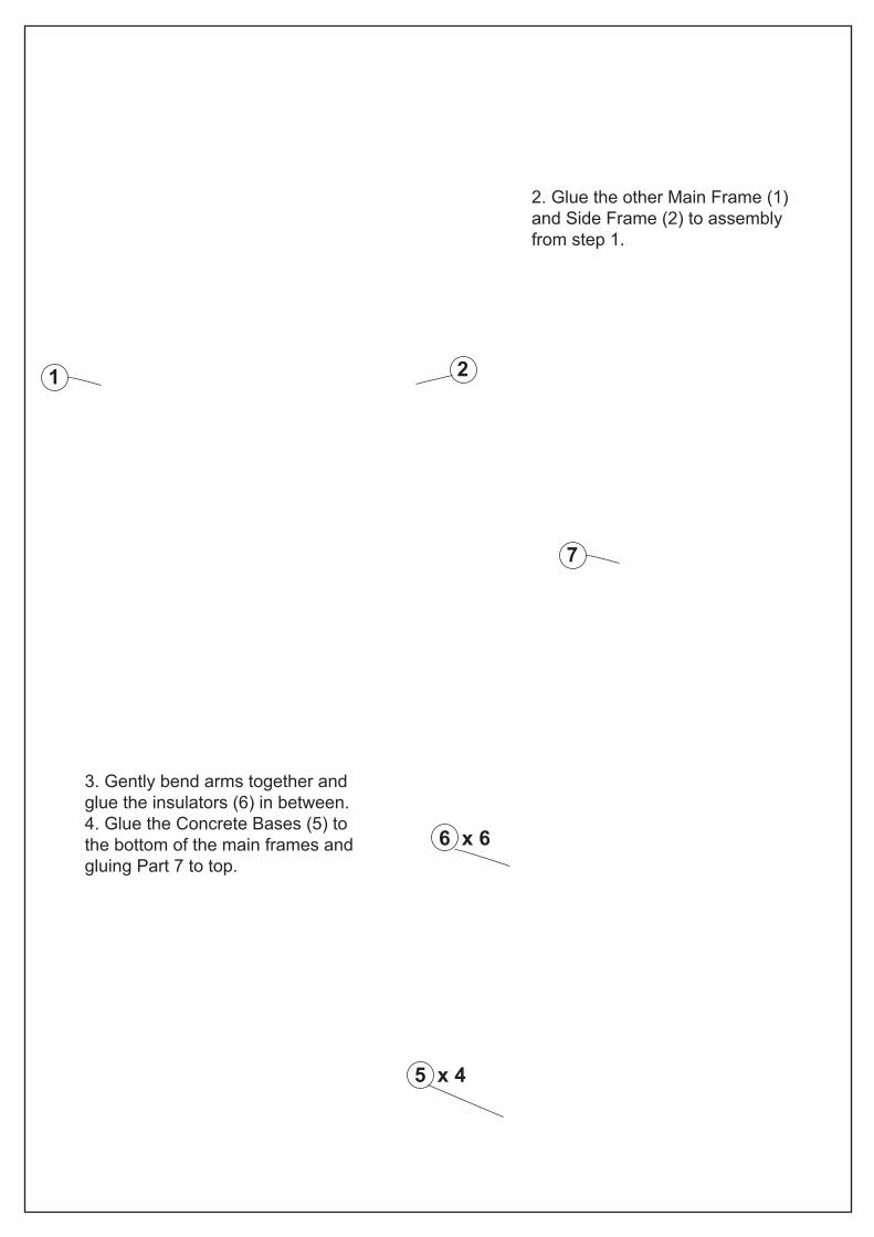
2. Glue the other Main Frame (1) and Side Frame (2) to assembly from step 1.
7
6 x 6
5 x 4
3. Gently bend arms together and glue the insulators (6) in between. 4. Glue the Concrete Bases (5) to the bottom of the main frames and gluing Part 7 to top.