ho structure kit 70' single track through girder bridge
TRANSCRIPT

HO Structure Kit70' SINGLE TRACK
THROUGH GIRDER BRIDGE933-4502
©2015 Wm. K. Walthers, Inc. Milwaukee, WI 53218 Printed in China I-933-4502
1211
8
7
11
8
7
11
87
11
8711
87
11
8 7
17
18
5 x23 x4
4 x4
19 x4
9
22
9
13 x4
6
Thanks for purchasing this Cornerstone® kit. Please read the instructions and study the drawings before starting construction. All parts are styrene, so use compatible glue and paint to finish your model. As part of the Cornerstone Engineered Bridge System (www.walthers.com/bridgesystem), your new model can easily be used with other Cornerstone bridges and accessories to create a custom structure for your railroad. PLEASE NOTE: Parts are included to build your choice of an Open or Ballasted Deck Bridge. Additional parts are included to finish your model with Walthers Code 83 Bridge Track (#948-886 or 949-899), plus flexible, sectional, hand-laid track or your own rail, all sold separately. An optional Center Girder (14) is included to model a double track or wider bridge by combining kits (each sold separately); this piece may be discarded or kept for future projects if building a stock kit.
While simple bridges had been around for centuries, railroads presented engineers with new challenges to design structures that could withstand the tremendous weight, vibration, pushing (compression) and pulling (tension) forces exerted by a moving train. In 1847, the sturdy “plate girder-bridge” was introduced, with individual iron plates and braces riveted together and directly to the ladder-shaped floor supports. With the rise of the steel industry, durable I-beams and sheet steel became readily available in various sizes, ushering in the next generation of plate girder bridges. Where clearances had to be maintained above highways, other rail lines and navigable waterways, engineers specified “through” designs, so called as the supporting plate girders were installed on top of the floor, and the track passed through them. Two styles of floors or decks were commonly used: open decks used longer bridge ties the width of the floor beams and were cheaper to build, but the ballasted deck with a steel pan to hold stan-dard ties and ballast, required less maintenance, and provided a smooth and quiet ride. Because of their versatility and adaptabil-ity, through girder bridges were easily widened for multi-track lines, used in multiples with piers where longer spans were needed, and also used in combination as approach spans for other types of bridges. Today, many of these sturdy steel bridges are still in daily railroad service, or have been preserved as part of recreational trails. For more products and modeling ideas, check out the complete Cornerstone Engineered Bridge System at www.walthers.com/bridgesystem.
Before starting construction...The Cornerstone Engineered Bridge System includes a wide range of acces-sories to complete installation of your new bridge, including:
Single-Track Railroad Bridge Concrete Abutments (933-4551) Single-Track Railroad Bridge Concrete Piers (933-4550) Bridge Shoes & Brackets (933-4559), which simplifies aligning & combining Cornerstone bridge kits for longer spans.
Single Track1) Make two Side Girder assemblies as follows: glue Top Cover Plate (2x 5), Curved End Cover Plates (2x 4), End Cover Plates (2x 3), to Side Girder (1); be sure raised pads on bottom of Right (9) and Left (2) Lower Cover Plates are at the end, and glue in place as shown.
2) Note the triangular recessed areas on the lower inside edge of each Side Girder assembly; align with Floor Beams (6) and glue a Plate Girder to either side.
Optional Deck Extension for CurveCUT TO FIT
16
146
1Optional DOUBLE TRACK Assembly
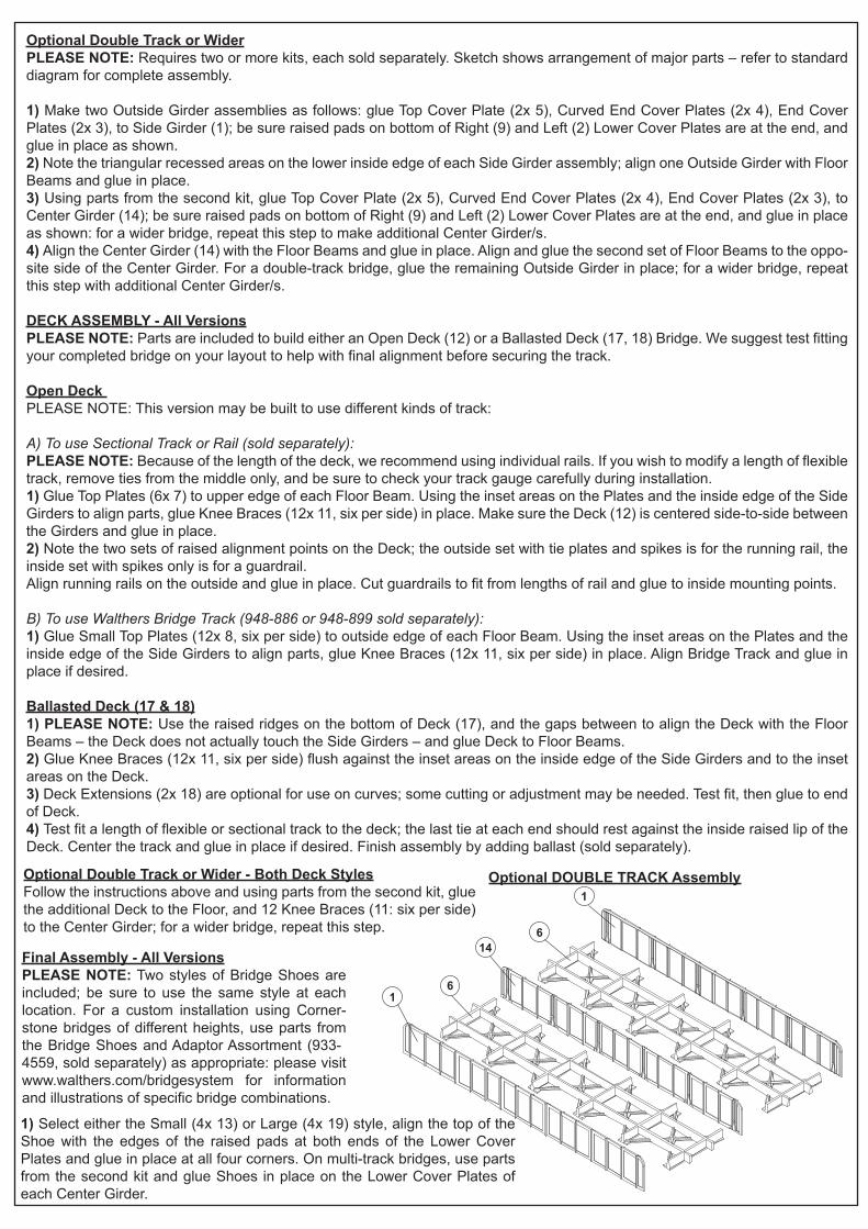
Optional Double Track or Wider PLEASE NOTE: Requires two or more kits, each sold separately. Sketch shows arrangement of major parts – refer to standard diagram for complete assembly.
1) Make two Outside Girder assemblies as follows: glue Top Cover Plate (2x 5), Curved End Cover Plates (2x 4), End Cover Plates (2x 3), to Side Girder (1); be sure raised pads on bottom of Right (9) and Left (2) Lower Cover Plates are at the end, and glue in place as shown. 2) Note the triangular recessed areas on the lower inside edge of each Side Girder assembly; align one Outside Girder with Floor Beams and glue in place.3) Using parts from the second kit, glue Top Cover Plate (2x 5), Curved End Cover Plates (2x 4), End Cover Plates (2x 3), to Center Girder (14); be sure raised pads on bottom of Right (9) and Left (2) Lower Cover Plates are at the end, and glue in place as shown: for a wider bridge, repeat this step to make additional Center Girder/s.4) Align the Center Girder (14) with the Floor Beams and glue in place. Align and glue the second set of Floor Beams to the oppo-site side of the Center Girder. For a double-track bridge, glue the remaining Outside Girder in place; for a wider bridge, repeat this step with additional Center Girder/s.
DECK ASSEMBLY - All VersionsPLEASE NOTE: Parts are included to build either an Open Deck (12) or a Ballasted Deck (17, 18) Bridge. We suggest test fitting your completed bridge on your layout to help with final alignment before securing the track.
Open Deck PLEASE NOTE: This version may be built to use different kinds of track:
A) To use Sectional Track or Rail (sold separately):PLEASE NOTE: Because of the length of the deck, we recommend using individual rails. If you wish to modify a length of flexible track, remove ties from the middle only, and be sure to check your track gauge carefully during installation.1) Glue Top Plates (6x 7) to upper edge of each Floor Beam. Using the inset areas on the Plates and the inside edge of the Side Girders to align parts, glue Knee Braces (12x 11, six per side) in place. Make sure the Deck (12) is centered side-to-side between the Girders and glue in place.2) Note the two sets of raised alignment points on the Deck; the outside set with tie plates and spikes is for the running rail, the inside set with spikes only is for a guardrail. Align running rails on the outside and glue in place. Cut guardrails to fit from lengths of rail and glue to inside mounting points.
B) To use Walthers Bridge Track (948-886 or 948-899 sold separately): 1) Glue Small Top Plates (12x 8, six per side) to outside edge of each Floor Beam. Using the inset areas on the Plates and the inside edge of the Side Girders to align parts, glue Knee Braces (12x 11, six per side) in place. Align Bridge Track and glue in place if desired.
Ballasted Deck (17 & 18) 1) PLEASE NOTE: Use the raised ridges on the bottom of Deck (17), and the gaps between to align the Deck with the Floor Beams – the Deck does not actually touch the Side Girders – and glue Deck to Floor Beams. 2) Glue Knee Braces (12x 11, six per side) flush against the inset areas on the inside edge of the Side Girders and to the inset areas on the Deck. 3) Deck Extensions (2x 18) are optional for use on curves; some cutting or adjustment may be needed. Test fit, then glue to end of Deck. 4) Test fit a length of flexible or sectional track to the deck; the last tie at each end should rest against the inside raised lip of the Deck. Center the track and glue in place if desired. Finish assembly by adding ballast (sold separately).
Optional Double Track or Wider - Both Deck StylesFollow the instructions above and using parts from the second kit, glue the additional Deck to the Floor, and 12 Knee Braces (11: six per side) to the Center Girder; for a wider bridge, repeat this step.
Final Assembly - All VersionsPLEASE NOTE: Two styles of Bridge Shoes are included; be sure to use the same style at each location. For a custom installation using Corner-stone bridges of different heights, use parts from the Bridge Shoes and Adaptor Assortment (933-4559, sold separately) as appropriate: please visit www.walthers.com/bridgesystem for information and illustrations of specific bridge combinations.
1) Select either the Small (4x 13) or Large (4x 19) style, align the top of the Shoe with the edges of the raised pads at both ends of the Lower Cover Plates and glue in place at all four corners. On multi-track bridges, use parts from the second kit and glue Shoes in place on the Lower Cover Plates of each Center Girder.