hng-14 - safety › roadway_dept › ... · refer to: hng-14 products division by your september 16...
TRANSCRIPT

Dennis H. O'Brien, P.E.Manager, Product PlanningIndustrial & ConstructionValmont Industries, Inc.Valley, Nebraska 68064
Dear Mr. O'Brien:
Refer to: HNG-14
Products Division
By your September 16 and 22, 1988, letters to Mr. Thomas 0. Willett, Director,of Office of Engineering, you requested Federal Highway Administration (FHWA)acceptance of steel breakaway slip-base luminaire supports for use onFederal-aid highway projects. .As you know, considerable effort has goneinto evaluating steel slip-base luminaire supports since you made yourrequest. Your cooperation and assistance in that effort is much appreciated.Enclosure I summarizes the tests FHWA has evaluated in reaching a decision onthe breakaway acceptability of steel slip-base luminaire supports.
In each of the tests shown in the sumnary the geometry of the slip-base wasnominally the same as California Department of Transportation's (Caltrans)Type 31 base, which is shown on Enclosure II, except that in one series oftests the keeper plate thickness was reduced to 0.0149 inches (28 gage). Thepole base plate in the type 31 base Is 1 inch thick, the lower slip plate is1 I/4 inches thick, and the anchor plate is 1 inch thick. We would also pointout that in all tests two of the slip-base clamp bolts lay in a line parallelto the direction of traffic and were on the street side of the pole.
from the summarization of tests it can be seen that there is considerablescatter in the results and that in some tests FHWA's maximum 16-foot-per-second breakaway change in velocity requirement was exceeded and in someinstances the test device was actually stopped. Because of the apparentlyunpredictable nature of the slip-base the testing effort was extended and atheoretical analysis of the slip-base release mechanism was undertaken. As aresult of this work we are now confident that safe slip-base luminairesupports can be configured that will be within substantial compliance withFHWA's breakaway requirements. Thus, steel slip-base luminaire supports willbe acceptable for use on Federal-aid highways if proposed by a State highwayagency provided they fall within the limitations setforth below:
Basic Type: Triangular, three-bolt base similar to Caltrans' Type 30 and 31bases (see Enclosure II).
Minimum Shaft Wall Thickness: 0.1196 inches for diameters up to 10 inches. .G
Bolt Circle Diameter: 14 inches (minimum).
Base Plate Thickness: 1 inch (minimum), 1 l/4 inches (maximum).

2
Lower Slip Plate Thickness: 1 l/4 inches (minimum), 1 l/2 inches (maximum).
Anchor Plate Thickness: 1 l/4 inches (maximum).
Steel Keeper Plate Thickness: 0.0149 inches before coating (28 gage) (maximum).
Height Top of Lower Slip Plate from Ground Line: 4 inches (maximum).
Clamp Bolt Type: Galvanized ASTM A325 with dry lubricant (Heads and nuts shall have heavy hex dimensions).
Clamp Bolt Size: 7/8-inch to 1 l/4-inch diameter.
Rectangular Clamp Bolt Washer Size: Length, width, and thickness shall be sufficient to prevent significant deflection (bending) when clamp bolt is loaded to its tensile capacity.
Hole in Clamp Bolt Rectangular Washer: Camp bolt diameter plus l/16 inch, with edges chamfered to prevent binding with radius under bolt head.
Clamp Bolt Tension: 8,000 pounds per bolt (maximum). In the absence of a more exact method of determining bolt tension the following maximum tightening torques shall be used:
Bolt diameter (inches1 7/8 1 118 1 I/ Torque (foot-pounds) 87 :5 104 III4
Finish: All faying surfaces to be galvanized, free of paint, and smooth and free of ridges, scallops, nicks, and burrs.
Mounting Height: 56 feet, 6 inches measured from bottom of pole base plate to centerline of luminaire mounting tenon (maximum).
Weight: 1,000 pounds (include luminaire, mast arm(s), pole, and base plate) (maximum).
M;;:irm Orientation: Mast arm may be parallel to a flat side of the base ed that side faces aDDrOaCh traffic or may pass over a clamp bolt
Tsee Enclosure III.)
Placement: The terrain about the pole base shall not inhibit translation of the pole and approach topography shall be such that a vehicle leaving the roadway at design speed and an angle of up to 25 degrees will not strike the pole at a height greater than were the pole located at the edge of the pavement. (The approach terrain will not cause an errant vehicle to become airborne.)

3
While the restrictions listed here are rather extensive and in some instances differ from some current practices, for example the clamp bolt tension, keeper plate thickness, and mast arm oriention prescribed differ from those in the Caltrans standard, one should not infer FHWA is apprehensive about the use of slip-base luminaire supports. It is just that our extensive study of these structures has given us an insight that leads us to believe they will work best and the public will be best served by adhering to the guidance we have outlined.
Sincerely yours,
d -a. & L. A. Staron Chief, Federal-Aid and Design Division
Enclosures
dab metric and Roadside Design acceptance letter number LS-16.

Enclosure 1, page 1 of 3
Agency Hastarm(s) Shaft Mounting Pole Diam. Slip Base Clamp Est. Clamp Keeper Impact Test Veh. Impact Occupant Test No. Height (ft) at base (in)Bolt Circle Bolt Bolt Force Plate Angle from TyRe and speed Change in
Date Length (ft) Length (ft) Total Wall Thick. Diameter Diameter 3 @ (lbs) ea Thickness Roadway Weight (m.p.h.) Velocity Weight (i) Weight (li) Weight (#) at base (in) (in) (in) (in) (degrees) (lbs) (f.p.s.)
*t*************t****************tt*t**********************fL***********************************t*******************t*************~*~***********~*********~***
CALTRANS CALIFORNIA TYPE 31 SLIP BASE
4u4 10.875 14 1 11,400 0.0359 30 '79 HONDA 19.9 8.5 JUL 26, 84 1;; 6:: 8:: 0.1793 1865
405 1:: 6;: 8z
10.875 14 1 11,200 0.0359 30 '79 HONOA 53.9 12.4 MAY 23, 85 0.1793 1885
406 15;
35 * 39.25 10 14 1 18,600 0.0359 30 '79 HOWDA 58.8 13.0 MAY 8,'87 627.4 0.25 l 1850
407 123;
35 l 39.25 0.;: l
14 1 12,200 0.0359 30 '79 HONDA 23.7 8.6 JUNE 23,'87 639.4 1840
CAPAiILITY VALHORT SLIP BASE TESTS - FOIL
87F033 1.33 AND 16 48.5 55.5 il.!!93
14 1 12,500 0.0359 0 FOIL BO8IE 19.8 14.5 MAR 12,'87 115 AND 112 630 964 1850
87F034 1.33 AND 16 48.5 55.5 10 14 1 12,500 0.0359 0 FOIL BO8IE 58.7 15.5 MAR 13,'87 115 AND 112 630 964 0.1793 1850
THIN WALL TESTS - FOIL
89FO23 1.33 AND 15 46.5833 53.42 14 1 12,500 0.0359 0 FOIL BOGIE 20.7 24.4 SEP 21,'89 120 AN0 107 415 744 O.::96 1850
89F024 1.33 AND 15 46.5833 53.42 0.!96
14 1 12,500 0.0359 0 '79 RABBIT 19.8 15.8 SEP 27,'89 120 AND 107 415 744 1850
8gF025 1.33 AND 15 46.5833 53.42 0.!:96
14 1 12,500 0.0359 0 '79 RABBIT 59.2 13.2 OCT 5,'89 120 AND 107 415 744 1850
89F026 1.33 AND 15 46.5833 53.42 0.;1:96
14 1 12,500 0.0359 0 FOIL 806IE 60.6 13.7 OCT 24,'89 120 AND 107 415 ,744 1850

Enclosure I, page 2 of 3
Agency Mastarm Shaft Mounting Pole Diam. Slip Base Height lft) at base (in)Bolt Circle
Clamp Est. Clamp Keeper Impact Impact Occupant Test No. Bolt Bolt Force Plate Angle from
Test Veh. Type and speed Change in
Date Length (ft) Length (ft) Total Wall Thick. Diameter Diameter 3 @ (lbs) ea Thickness Weight (I) Weight (i) Weight (t) at base (in)
Roadway (in) (degrees)
Weight (m.p.h.) Velocity (in) (in) (lbs) (f.p.s.)
**t**********n*****+*****i**+t*****++****~********************************************************t************+******t*****tt*************************************** CLAMP FORCE STUDY - FOIL
BgF005 None APR 12,'89
89FOO6 * APR lg.'89
89FOO7 I APR 20,'89
8gFOO8 * APR 24,'89
B9FDO9 * APR 25,'89
89FOlO Y APR 26,'89
8gFOll * APR 26,'89
8gFO12 q
APR 27,'89
89F014 q
MAY 19,'89
8gFO15 * MAY 24,'Bg
8gFOlL I MAY 25,'89
8gFO17 * MAY 31,'89
30.25 275
* *
* It
* *
* *
l
l
Y
*
l
*
* *
I
*
n
*
n
l
None 275
* l
(I *
I) *
* I
I I
* ”
* *
* I
l
.
* (I
l
l
oliZ45
”
*
*
I
*
.
l
n
I
l
I
*
*
*
l
*
*
l
I
*
.
I
14
l
*
*
1,965
3,928
5,891
7,614
9,817
11,780
9,817
11,780
13,743
7,614
15,808
5,891
0.0359
*
*
.
*
I
*
l
*
I
*
*
0
0
0
0
0
0
0
0
0
0
0
0
FOIL BOGIE 1850
I) *
l
*
* *
l
l
* l
* I
* I
. I
l
*
" l
* *
20.6 6.5
20.7 5.9
20.7 8.3
20.5 .~ 6.4
20.8 23.2
20.7 20.6
20.5 7.7
20.6 36.9 l *
20.4 22.7
20.5 14.8
20.4 18.2
20.6 21.4
* A P-foot high steel tube with 0.25 in. wall thickness was welded to.the bottom of a 33 foot tall pole-which had a wall thickness of 0.1196 in. **************t********************************************************~*****************t*********t******t*****************************************~***~*

. Enclosure I, page 3 of 3
Agency Mastarm Shaft Mounting Pole Oiam. Slip Base Clamp Est. Clamp Keeper Impact Test'Veh. Impact Test No. Height (ft) at base (in)Bolt Circle Bolt Bolt Force Plate
Occupant
Diameter 3 @ (lbs) ea Thickness Angle from Type and speed
Date Length (ft) Length (ft) Total Wall Thick. Diameter Change in
Weight (t) Weight (1) Weight (#) at base (in) (in) (in) Roadway
(in) (degrees) Weight (m.p.h.) (lbs)
Velocity (f.p.s.)
KEEPER PLATE STUDY - FOIL
10.0 0.1793
* Y
14
I
*
12,500 0.0359 0 FOIL PNOLM 19.9 25.9 1850
" NDNE
l NONE
* l
*
* n
*
l l
I
q * *
l l
l
q I *
I) Y *
I * q
l ” I
* * *
* * l
19.8
./. 19.8
8.8
13.2
* NONE 19.9 11.1
* 0.0149
0.0149
0.0149
0.0149
0.1049
0.0149
0.0149
0.0149
20 16.9
* 19.8 35 **
3,600 5.6
3,600 7
3,600 6.4
9,000
9,000
8,000
20
20
20
/ 20
20
20
11.8
35.4 l *
17.7
YOPO23 None 30.83 None 4124790 None 486 486
l
* 908024
4/25/90
9OPO25 4/25/90
9OPO26 4726790
YOP027 4/26/90
9OPO28 5/l/90
9OPO29 5/2/90
9OPO32 5/30/90
9OPO33 5/31/90
. I
I
l
* *
* l
* I
* *
l
*
* *
* *
* l
l
l
* *
* *
* ”
Y
II
* *
l
I
I
*
* q
l
*
l
*
”
*
(I
l
l
* *
* *
* *
*
* *
l
I
l
”
l
*
9OPO34 * I 5/31/90 " *
9OPo35 * * 6/05/90 * l
9OPO36 * * 6/Ob/gO * "
(I
l
I
*
. l
l
l
l
I)
n
n
l * Value includes rebound, thus exceeds'inpact speed.

PLAN - TYPICAL BASE PLATE
r7 1
WELDED OPTION v&-
PLAN - BOTTOM PLATES SECTION E-E
ELEVATION - NON - SLIP BASE ELEVATION-SLIP BASE

Enclosure II ILuminaire Slip Base Orientation
Q Directionof Adjacent
I Traffic
u
Directionof AdjacentTraffic
Directionof AdjacentTraffic
Best BreakawayPerformanceAcceptable
Best Compromiseto avoid undesirableorientationAcceptable
Worst BreakawayPerformanceNot Recommended
*
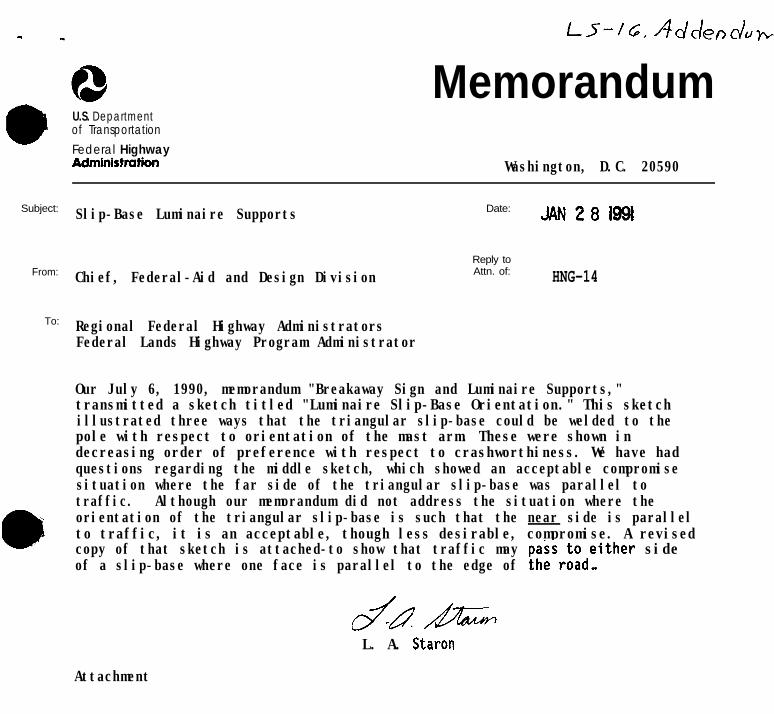
Subject:
From:
To:
MemorandumU.S. Departmentof TransportationFederal HighwayAdministrotbn Washington, D.C. 20590
Slip-Base Luminaire Supports Date: JAN28199l
Reply to
Chief, Federal-Aid and Design Division Attn. of: HNG-14
Regional Federal Highway AdministratorsFederal Lands Highway Program Administrator
Our July 6, 1990, memorandum "Breakaway Sign and Luminaire Supports,"transmitted a sketch titled "Luminaire Slip-Base Orientation." This sketchillustrated three ways that the triangular slip-base could be welded to thepole with respect to orientation of the mast arm. These were shown indecreasing order of preference with respect to crashworthiness. We have hadquestions regarding the middle sketch, which showed an acceptable compromisesituation where the far side of the triangular slip-base was parallel totraffic. Although our memorandum did not address the situation where theorientation of the triangular slip-base is such that the near side is parallelto traffic, it is an acceptable, though less desirable, compromise. A revisedcopy of that sketch is attached-to show that traffic mayof a slip-base where one face is parallel to the edge of
;;isr;;deither side.
lY+zdAF
L. A. Staron
Attachment

,~ttac!-mentLuminaire Slip Base Orientation
.
D-,-L,...-..8eSt ureanawayPerformance,Acceptable
/\ Directionof AdjacentTraffic
Preferred Compromise to avoid LessUndesirable orientation, Acceptable
desirable compromise,Acceptable
8
II.Y\
L+( 3
Location of Location of ’ I
Adjacent Traffic Adjacent Traffic ! 1f” t@l\ .I‘4
Directionof AdjacentTraffic
Worst BreakawayPerformance,Not Recommended
,

400 Seventh St., SW. Washington. DC. 20590
Refer to: HNG-14
SEP 30 1993
Dennis H. O'Brien, P.E. ~ Manager of Product Pl,anning Industrial & Construction Products Division. Valmont Industries, Inc. Valley, Nebraska 68064-0358
Dear Mr. O'Brien:,
Thank you for your letter of September 2 requesting clarification of acceptable mounting heights for breakaway luminaire supports. In general, dimensions suc,has mounting height, pole diameter and mass, bolt size and torque, should not exceed those af the tested hardware. We place these limitations in our hardware acceptance letters to assure that the hardware used in the field is no less forgiving of the errant motorist than the hardware used in the crash tests. In our memorandum of June 15, 1989, to the Federal Highway Regional Administrator in Portland, Oregon, where we discussed luminaire support recommendations, however, we stated:
c . . . the advice is not nearly as forceful on the issue of height as it is on the need to limit weigh~t. After considering the likely effect of a 60-foot pole in comparison to a 55-foot pole, we conclude there would be little difference for an impacting vehicle. Therefore, we would recommend allowing 60-foot mounting heights (base of pole to level of luminaire.) However, we also believe this should be considered an absolute maximum in the absence of further study and testing to investigate the effects of pole height and weight."
We still believe this to be sound advice, even under the 1985 American Association of State Highway and Transportation Officials breakaway criteria. Therefore, luminaire supports which are considered breakaway by way of our Geometric and Roadside Design Acceptance letters LS-16 and LS-25 dated June 29, 1990, and October 10, 1991, respectively may use a nominal mounting height of up to 18.3 m (60 feet) as requested in your letter.
You also wished to alert us to the need for increasing the pole wall thickness when the height is raised. This causes us some concern, as the crash tested hardware found acceptable by way of LS-25 weighed 409 kg (902 pounds) ~This approaches the 454 kg (lOOO-pound) maximum mass we have set for breakaway luminaire supports to control the risk to vehicle occupants from a pole's

2
falling on a vehicle's roof. We will not sanction pole plus mast arm plusluminaire masses in excess of 454 kg (1000 pounds) without automobile crashtests to confirm their acceptability.
Sincerely yours,
Lawrence A. StaronChief, Federal-Aid and Design Division
Supplement to Geometric and Roadside Design Acceptance LettersLS-16 and LS-25