hmi instrument calibration plan - stanford...
TRANSCRIPT

Instrument Calibration Plan December 13, 2006
HMI
Instrument Calibration
Plan
1

Instrument Calibration Plan December 13, 2006
2

Instrument Calibration Plan December 13, 2006
Contents
1 Introduction 5
2 Levels of Calibrations 6
2.1 Component Tests . . . . . . . . . . . . . . . . . . . . . . . . . . . . . . . . . . . . . . . 62.2 Sun Test . . . . . . . . . . . . . . . . . . . . . . . . . . . . . . . . . . . . . . . . . . . . 62.3 In-Air Calibration . . . . . . . . . . . . . . . . . . . . . . . . . . . . . . . . . . . . . . . 62.4 Vacuum Calibration . . . . . . . . . . . . . . . . . . . . . . . . . . . . . . . . . . . . . . 62.5 Spacecraft Tests . . . . . . . . . . . . . . . . . . . . . . . . . . . . . . . . . . . . . . . . 62.6 On-Orbit Commissioning . . . . . . . . . . . . . . . . . . . . . . . . . . . . . . . . . . . 72.7 On-orbit Periodic . . . . . . . . . . . . . . . . . . . . . . . . . . . . . . . . . . . . . . . 7
3 Equipment and Setups 8
3.1 Polarization Calibration Unit . . . . . . . . . . . . . . . . . . . . . . . . . . . . . . . . . 83.2 In-Air Configurations . . . . . . . . . . . . . . . . . . . . . . . . . . . . . . . . . . . . . 83.3 Vacuum Setup . . . . . . . . . . . . . . . . . . . . . . . . . . . . . . . . . . . . . . . . . 8
4 Calibration Procedures 12
4.1 Image Quality . . . . . . . . . . . . . . . . . . . . . . . . . . . . . . . . . . . . . . . . . 124.1.1 Image scale, camera co-alignment and absolute roll. . . . . . . . . . . . . . . . . 124.1.2 Distortion . . . . . . . . . . . . . . . . . . . . . . . . . . . . . . . . . . . . . . . 134.1.3 Focus and field curvature . . . . . . . . . . . . . . . . . . . . . . . . . . . . . . . 144.1.4 MTF . . . . . . . . . . . . . . . . . . . . . . . . . . . . . . . . . . . . . . . . . 164.1.5 Ghosts and scattered light . . . . . . . . . . . . . . . . . . . . . . . . . . . . . . 16
4.2 CCD and Camera . . . . . . . . . . . . . . . . . . . . . . . . . . . . . . . . . . . . . . . 164.3 Contamination and Vignetting . . . . . . . . . . . . . . . . . . . . . . . . . . . . . . . . 17
4.3.1 Contamination - general. . . . . . . . . . . . . . . . . . . . . . . . . . . . . . . . 174.3.2 Contamination on waveplates and focus blocks. . . . . . . . . . . . . . . . . . . . 174.3.3 Vignetting - general. . . . . . . . . . . . . . . . . . . . . . . . . . . . . . . . . . 174.3.4 Vignetting - path differences. . . . . . . . . . . . . . . . . . . . . . . . . . . . . . 17
4.4 Image Motions . . . . . . . . . . . . . . . . . . . . . . . . . . . . . . . . . . . . . . . . 174.5 Filter Transmission . . . . . . . . . . . . . . . . . . . . . . . . . . . . . . . . . . . . . . 18
4.5.1 Wavelength Dependence . . . . . . . . . . . . . . . . . . . . . . . . . . . . . . . 184.5.2 Spatial Dependence . . . . . . . . . . . . . . . . . . . . . . . . . . . . . . . . . . 184.5.3 Angular Dependence . . . . . . . . . . . . . . . . . . . . . . . . . . . . . . . . . 184.5.4 Artifacts from moving elements . . . . . . . . . . . . . . . . . . . . . . . . . . . 184.5.5 Temperature Dependence . . . . . . . . . . . . . . . . . . . . . . . . . . . . . . . 18
3
Instrument Calibration Plan December 13, 2006
4.5.6 Shutter and Hollow Core Motor Repeatability . . . . . . . . . . . . . . . . . . . . 194.5.7 Overall throughput . . . . . . . . . . . . . . . . . . . . . . . . . . . . . . . . . . 19
4.6 Polarization . . . . . . . . . . . . . . . . . . . . . . . . . . . . . . . . . . . . . . . . . . 204.6.1 Overall polarization . . . . . . . . . . . . . . . . . . . . . . . . . . . . . . . . . 204.6.2 Focus block birefringence . . . . . . . . . . . . . . . . . . . . . . . . . . . . . . 204.6.3 Thermal effects . . . . . . . . . . . . . . . . . . . . . . . . . . . . . . . . . . . . 214.6.4 HCM repeatability . . . . . . . . . . . . . . . . . . . . . . . . . . . . . . . . . . 214.6.5 On orbit calibration . . . . . . . . . . . . . . . . . . . . . . . . . . . . . . . . . . 21
4.7 Observables . . . . . . . . . . . . . . . . . . . . . . . . . . . . . . . . . . . . . . . . . . 214.8 Thermal Effects . . . . . . . . . . . . . . . . . . . . . . . . . . . . . . . . . . . . . . . . 224.9 Image Stabilization System . . . . . . . . . . . . . . . . . . . . . . . . . . . . . . . . . . 224.10 Alignment Mechanism . . . . . . . . . . . . . . . . . . . . . . . . . . . . . . . . . . . . 22
4
Instrument Calibration Plan December 13, 2006
1 Introduction
The purpose of this document is to describe the cal-ibrations which will be performed on the HMI in-strument and its various pieces.
It is essential that such calibrations are per-formed in order to be able to meet even the mini-mum science requirements and performing a com-prehensive set of calibrations will allow us to maxi-mize the overall science return.
Section 2 gives an overview of the various stagesof calibrations followed by a section describingsome of the equipment and setups used. Section 4describes the different calibrations to be performedordered by subject. For each subject the procedureswill be described and an outline of the analysis pro-vided.
This plan only covers the calibration of the op-tical system and closely associated mechanical orelectrical systems to the extent that they directly af-fect the optical performance. In other words calibra-tions of thermistors etc. will not be captured here.
Many of the calibration procedures described inthis document have been used previously on previ-ous experiments such as MDI and Solar-B FPP andare as such not new developments.
This plan does not describe all the details of thecalibrations to be performed or of the associatedanalysis. The former is captured in the associatedshop orders and the latter in the reports capturingthe results. As such the present document directlydrives both the shop orders and the reports.
This document is to a large extend based on thediscussions in the Instrument Performance Docu-ment (IPD). In particular the requirements are de-fined there (see Tables 1, 4, 5 and 6).
The calibration of the instrument is also closelyrelated to the Integration and Test (I&T), Alignmentand Verification for which there are separate plans.The purpose of the calibration activities is not toprovide formal verification of requirements.
In addition to the end-to-end tests described inthis document several of the individual optical com-ponents (eg. lenses) have been tested. While these
measurements will be incorporated as needed, nodescription of these tests are provided here.
Some of the subsystems (such as the Lyot) aswell as several of the more complex calibrations(such as the filter transmission and polarization)have separate plans, and the details will only besummarized here.
After the calibrations have been completed sev-eral reports will be written, including
• Overall calibration report
• Detailed reports for each item
• Contributions to the SDO Book
The detailed reports will contain details of thecalibrations run, the analysis done and the resultsobtained. The overall report will summarize the re-sults and reference the detailed reports.
5

Instrument Calibration Plan December 13, 2006
2 Levels of Calibrations
The following subsections describe the differentstages of calibrations performed. These effortsmostly consist of measurements that are used for af-ter the fact calibration of the data.
2.1 Component Tests
Some of the quantities needed for the calibration canonly, or most conveniently, be measured before finalintegration of the instrument. The calibrations willthus be performed at different levels of assembly, asappropriate.
Examples of items tested at the parts level in-clude individual waveplates, polarizers, Calcite ele-ments for the Lyot and various powered optics ele-ments. All parts are inspected, measured and pho-tographed to verify that they are undamaged andmeet their mechanical specifications. Also the ori-entation of parts are noted as they are calibrated.
Subassemblies to be tested include the individ-ual Lyot elements.
Assemblies to be tested include the Lyot and theMichelsons.
The tests in this section are generally not de-scribed in this calibration plan. Most of them areI&T activities and separate documents describe theother tests.
2.2 Sun Test
The first calibration exercise of the integrated instru-ment is the so-called Sun Test. The purposes of thisinclude:
• Learn how to operate the HMI optics package.
• Learn how to characterize/calibrate the instru-ment. In some cases, obtain initial calibrationparameters.
• Discover gross errors in design or workman-ship of the HMI optics package.
• Determine position of focus to set the finalshim on the telescope secondary lens.
• Determine position of waveplates in the po-larization selectors to set the final orientationrelative to HCM step locations.
• Develop procedures and software for the fol-lowing calibration activities.
2.3 In-Air Calibration
The first formal calibration activity is the In-Aircalibration. The main purposes of this activity in-cludes:
• Obtain calibration data which can not be ob-tained during the vacuum calibration. This in-cludes certain aspects of the polarization cal-ibrations and image quality measurements re-quiring the stimulus telescope to be mountedrigidly to the instrument.
• Practice the procedures which will be usedduring the vacuum calibration.
2.4 Vacuum Calibration
This is the main calibration activity. The noise herewill be substantially less than in air.
2.5 Spacecraft Tests
Several calibrations will be repeated once the instru-ment has been integrated with the spacecraft. Themain purpose of these tests is to verify that the cali-bration has not changed.
Since these tests are mostly for trending andsince no calibrations depend on data taken duringthese tests, they are not discussed further in this doc-ument. Instead they are described in the CPT andSPT plans.
6
Instrument Calibration Plan December 13, 2006
2.6 On-Orbit Commissioning
Many of the calibrations will be repeated on-orbit.In addition some calibrations are only possible ormost conveniently performed after launch. This in-cludes aspects of the polarization calibration and thedistortion.
In this document only those calibrations whichdepend on being on orbit will be discussed in de-tail. Other calibrations performed at this level areidentical to those done in the vacuum calibration.
The overall plan for calibrations included in thecommissioning is part of the In-Flight CheckoutPlan.
2.7 On-orbit Periodic
Several calibration procedures will be repeated atvarying intervals during the mission. The main pur-pose is to check for any drifts and to update variouscalibration tables to compensate for any changes.
The frequency of these range all the way fromdaily to once or twice during the mission. Most ofthe calibrations are similar to those described for theground calibrations of the integrated instrument.
As we gain experience with the instrument onorbit procedures may be added or deleted and theexact frequency of the various tests will be deter-mined.
7
Instrument Calibration Plan December 13, 2006
3 Equipment and Setups
The majority of the equipment is described in theI&T plan and will not be described here.
3.1 Polarization Calibration Unit
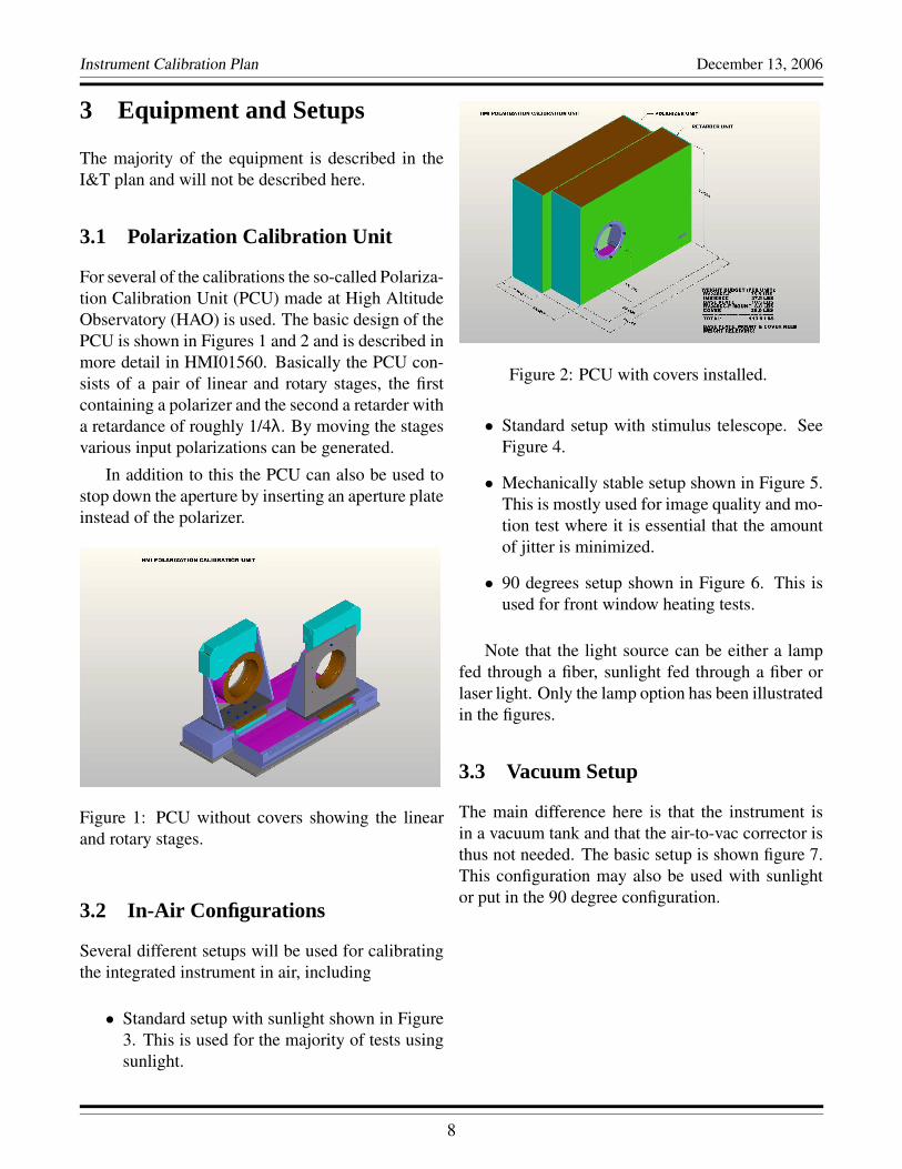
For several of the calibrations the so-called Polariza-tion Calibration Unit (PCU) made at High AltitudeObservatory (HAO) is used. The basic design of thePCU is shown in Figures 1 and 2 and is described inmore detail in HMI01560. Basically the PCU con-sists of a pair of linear and rotary stages, the firstcontaining a polarizer and the second a retarder witha retardance of roughly 1/4λ. By moving the stagesvarious input polarizations can be generated.
In addition to this the PCU can also be used tostop down the aperture by inserting an aperture plateinstead of the polarizer.
Figure 1: PCU without covers showing the linearand rotary stages.
3.2 In-Air Configurations
Several different setups will be used for calibratingthe integrated instrument in air, including
• Standard setup with sunlight shown in Figure3. This is used for the majority of tests usingsunlight.
Figure 2: PCU with covers installed.
• Standard setup with stimulus telescope. SeeFigure 4.
• Mechanically stable setup shown in Figure 5.This is mostly used for image quality and mo-tion test where it is essential that the amountof jitter is minimized.
• 90 degrees setup shown in Figure 6. This isused for front window heating tests.
Note that the light source can be either a lampfed through a fiber, sunlight fed through a fiber orlaser light. Only the lamp option has been illustratedin the figures.
3.3 Vacuum Setup
The main difference here is that the instrument isin a vacuum tank and that the air-to-vac corrector isthus not needed. The basic setup is shown figure 7.This configuration may also be used with sunlightor put in the 90 degree configuration.
8

Instrument Calibration Plan December 13, 2006
Standard setup with sunlight
HMIHMI
Air
-to
-vac
PCUPCU
Po
lari
zer
Ret
ard
er
Heliostatfold
mirror
Figure 3: Standard calibration setup with sunlight.
Standard Setup With Stimulus Telescope
HMIHMI
Stimulus telescope
Telescope Target Lightsource
Air
-to
-vac
PCUPCU
Po
lari
zer
Ret
ard
er
Figure 4: Standard calibration setup with stimulus telescope.
9

Instrument Calibration Plan December 13, 2006
Mechanically stable setup
Air
-to
-vac
HMIHMI
Stimulus telescope
Telescope Target Lightsource
Figure 5: Mechanically stable setup.
90 Degree setup
Sti
mu
lus
tele
sco
pe
Tel
esco
pe
Tar
get
Lig
ht
sou
rce
Air
-to
-vac
HMIHMI
Heliostatfold
mirror
Flipmirror
Figure 6: Setup for front window heating tests. The equivalent setup with sunlight has not been shown.
10

Instrument Calibration Plan December 13, 2006
Vacuum tank setup
HMIHMI
Stimulus telescope
Telescope Target Lightsource
PCUPCUP
ola
rize
r
Ret
ard
er
Figure 7: Vacuum tank setup. The equivalent setup with sunlight has not been shown.
11

Instrument Calibration Plan December 13, 2006
4 Calibration Procedures
In this section the calibrations to be performed aredescribed. The different aspects of the calibrationhave been ordered by subject.
Unless explicitly stated all calibrations are donein air and in vacuum. The setup is described for eachitem with particular emphasis on calibrations whichhave particular constraints.
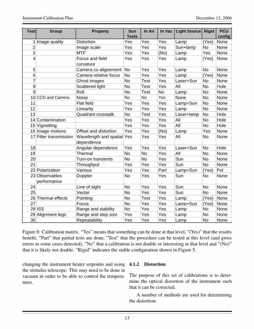
A summary of the tests done at various levels isshown in Figure 8. Note that in some cases calibra-tions are shown to be performed at different times.In some cases only one of these are required. Alsonote that as experience with various setups is gainedsome of them may be added or deleted at variousstages. Finally note that many details described inthis section have been left out of the calibration ma-trix.
4.1 Image Quality
These calibrations cover a variety of issues regard-ing the optical performance and will be performedon both cameras.
4.1.1 Image scale, camera co-alignment and ab-solute roll.
The purpose is to determine the image scale as afunction of focus position.
Solar images from the ground. This is probablythe easiest and most accurate measurement on theground. The apparent solar diameter in pixels is es-timated from an image and the apparent solar diam-eter in arcseconds is determined from an ephemeris.
Stimulus telescope and theodolite. The imagescale can also be determined by measuring thealignment leg offset using a theodolite and compar-ing that to the shift in pixels of a target in the stim-ulus telescope. This method is probably less accu-rate, but avoids uncertainties associated with the he-liostat.
On-orbit. This is similar to using the solar im-ages on the ground and will be done continuouslyto monitor aging effects, in particular those affect-ing the thermal properties.
Due to the uncertainty in the physical radius ofthe Sun the most accurate measurement of the abso-lute image scale will be from planetary transits andthis will be done whenever possible. To do this reg-ular images are taken during the transit. The onlysuch transit during the prime mission is a Venustransit in 2012.
Considerations include not using data where thethermal environment has changed too much due tothe decreased level of sunlight during solar eclipses.This effectively limits the calibrations using themoon to the time around first contact.
The analysis consists of measuring the positionof the object as a function of time and correlatingthis with an ephemeris.
Calmode image scale. This will also be deter-mined by measuring the diameter of the image ofthe aperture stop.
Co-alignment. This activity determines the offsetand roll difference between the two optical paths.This is done by mounting a high contrast fine struc-ture target in the stimulus telescope and correlatingsub-areas of the image. The plan is to use the ran-dom noise target. Some of the details of the correla-tions are described under distortion.
Absolute roll. Venus and Mercury transits and so-lar eclipses present the only way to accurately esti-mate the absolute roll angle of the instrument.
Considerations are similar to those for the im-ages scale above.
The absolute roll will, of course, also be esti-mated on the ground to the accuracy possible.
Thermal effects. The main effect to check forhere is any change in the overall instrument pointingor the offset between the CCDs. This can be done by
12
Instrument Calibration Plan December 13, 2006
1234
567891011121314151617
181920212223
2425262728293031
A B C D E F G H I J K L N OTest Group Property Sun
TestsIn Air In Vac Light Source Rigid PCU
config1 Image quality Distortion Yes Yes Yes Lamp (Yes) None2 Image scale Yes Yes Yes Sun+lamp No None3 MTF Yes Yes (No) Lamp Yes None4 Focus and field
curvatureYes Yes Yes Lamp (Yes) None
5 Camera co alignement No Yes Yes Lamp No None6 Camera relative focus No Yes Yes Lamp (Yes) None7 Ghost images No Test Yes Laser+Sun No None8 Scattered light No Test Yes All No Hole9 Roll No Test No Lamp No None
10 CCD and Camera Noise No No Yes None No None11 Flat field Yes Yes Yes Lamp+Sun No None12 Linearity Yes Yes Yes Lamp No None13 Quadrant crosstalk No Test Yes Laser+lamp No Hole14 Contamination Yes Yes Yes All No Hole15 Vignetting Yes Yes Yes All No Hole16 Image motions Offset and distortion Yes Yes (No) Lamp Yes None17 Filter transmission Wavelength and spatial
dependenceYes Yes Yes All No None
18 Angular dependence Yes Yes Yes Laser+Sun No Hole19 Thermal No No Yes All No None20 Turn-on transients No No Yes Sun No None21 Throughput Yes Yes Yes Sun No None22 Polarization Various Yes Yes Part Lamp+Sun (Yes) Pol23 Observables
performanceDoppler No Yes Yes Sun No None
24 Line of sight No Yes Yes Sun No None25 Vector No Yes Yes Sun No None26 Thermal effects Pointing No Test Yes Lamp (Yes) None27 Focus No Yes Yes Lamp+Sun (Yes) None28 ISS Range and stability No Yes Yes Lamp No None29 Alignment legs Range and step size Yes Yes Yes Lamp No None30 Repeatability Yes Yes Yes Lamp No None
Figure 8: Calibration matrix. ”Yes” means that something can be done at that level, ”(Yes)” that the resultsbenefit, ”Part” that partial tests are done, ”Test” that the procedure can be tested at this level (and grosserrors in some cases detected), ”No” that a calibration is not doable or interesting at that level and ”(No)”that it is likely not doable. ”Rigid” indicates the stable configuration shown in Figure 5.
changing the instrument heater setpoints and usingthe stimulus telescope. This may need to be done invacuum in order to be able to control the tempera-tures.
4.1.2 Distortion
The purpose of this set of calibrations is to deter-mine the optical distortion of the instrument suchthat it can be corrected.
A number of methods are used for determiningthe distortion.
13
Instrument Calibration Plan December 13, 2006
Direct measurement. With this method a wellcharacterized target is placed in the focus of thestimulus telescope and the resulting image on thedetector is analyzed.
The plan is to use a set of Ronchi rulings rotatedto 0, 90, 180 and 270 degrees. Important considera-tions in the setup include having the target properlyfocused, mounting the targets perpendicular to thestimulus telescope optical axis and knowing wherethe stimulus telescope optical axis is located on theimage.
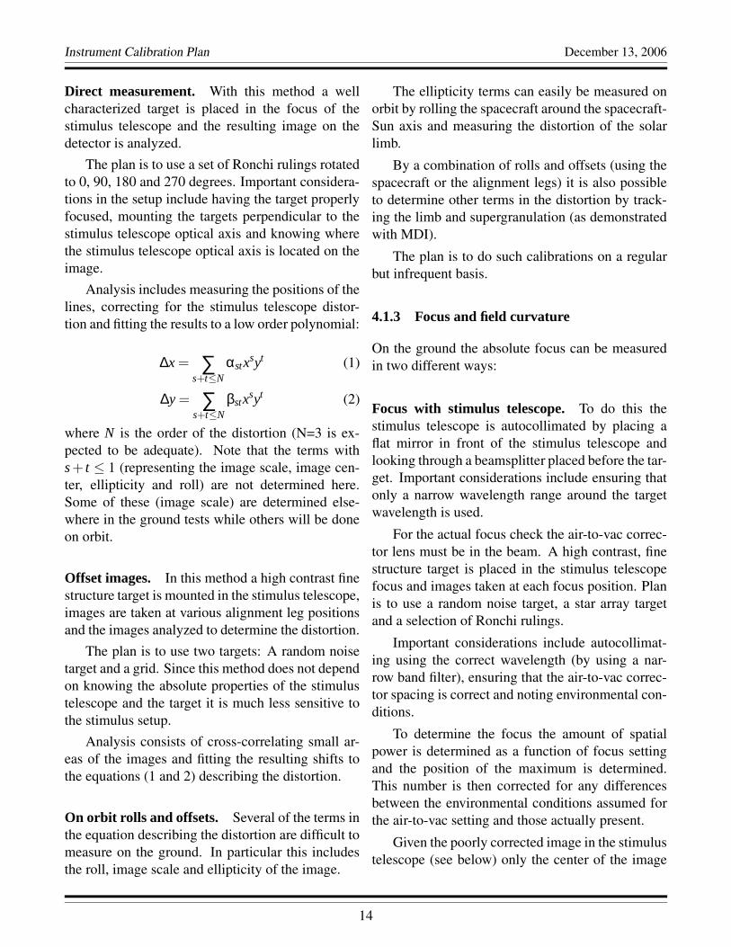
Analysis includes measuring the positions of thelines, correcting for the stimulus telescope distor-tion and fitting the results to a low order polynomial:
∆x = ∑s+t≤N
αstxsyt (1)
∆y = ∑s+t≤N
βstxsyt (2)
where N is the order of the distortion (N=3 is ex-pected to be adequate). Note that the terms withs + t ≤ 1 (representing the image scale, image cen-ter, ellipticity and roll) are not determined here.Some of these (image scale) are determined else-where in the ground tests while others will be doneon orbit.
Offset images. In this method a high contrast finestructure target is mounted in the stimulus telescope,images are taken at various alignment leg positionsand the images analyzed to determine the distortion.
The plan is to use two targets: A random noisetarget and a grid. Since this method does not dependon knowing the absolute properties of the stimulustelescope and the target it is much less sensitive tothe stimulus setup.
Analysis consists of cross-correlating small ar-eas of the images and fitting the resulting shifts tothe equations (1 and 2) describing the distortion.
On orbit rolls and offsets. Several of the terms inthe equation describing the distortion are difficult tomeasure on the ground. In particular this includesthe roll, image scale and ellipticity of the image.
The ellipticity terms can easily be measured onorbit by rolling the spacecraft around the spacecraft-Sun axis and measuring the distortion of the solarlimb.
By a combination of rolls and offsets (using thespacecraft or the alignment legs) it is also possibleto determine other terms in the distortion by track-ing the limb and supergranulation (as demonstratedwith MDI).
The plan is to do such calibrations on a regularbut infrequent basis.
4.1.3 Focus and field curvature
On the ground the absolute focus can be measuredin two different ways:
Focus with stimulus telescope. To do this thestimulus telescope is autocollimated by placing aflat mirror in front of the stimulus telescope andlooking through a beamsplitter placed before the tar-get. Important considerations include ensuring thatonly a narrow wavelength range around the targetwavelength is used.
For the actual focus check the air-to-vac correc-tor lens must be in the beam. A high contrast, finestructure target is placed in the stimulus telescopefocus and images taken at each focus position. Planis to use a random noise target, a star array targetand a selection of Ronchi rulings.
Important considerations include autocollimat-ing using the correct wavelength (by using a nar-row band filter), ensuring that the air-to-vac correc-tor spacing is correct and noting environmental con-ditions.
To determine the focus the amount of spatialpower is determined as a function of focus settingand the position of the maximum is determined.This number is then corrected for any differencesbetween the environmental conditions assumed forthe air-to-vac setting and those actually present.
Given the poorly corrected image in the stimulustelescope (see below) only the center of the image
14

Instrument Calibration Plan December 13, 2006
(where the autocollimation is performed) should beused.
Focus with heliostat. To do this images are takenat different focus positions and the sharpness of thesolar limb is measured. Again the air-to-vac correc-tor needs to be installed.
Important considerations include ensuring thatthe air-to-vac corrector spacing is correct and not-ing environmental conditions. It is also essential toensure that the heliostat is not introducing any un-known focus offset. To ensure this a comprehensiveseries of thermal tests are planned.
Field curvature with stimulus telescope. To de-termine the field curvature the focus position is de-termined as a function of position in the image.
Important considerations include those above, aswell as ensuring that the stimulus telescope targetsare mounted perpendicular to the optical axis of thestimulus telescope. Given that only the focus vari-ations are to be determined here, the environmentalconditions are of less concern.
The analysis is similar to the focus analysisabove. To disentangle the stimulus telescope fieldcurvature from that of the instrument two methodswill be used. One is to subtract a model based on aray trace, the other is to use offset images (see thedistortion discussion). This calibration is done onboth cameras.
Relative focus. The relative focus of the two CCDcameras is fairly straightforward to measure by do-ing a field curvature measurement, as describedabove, with both cameras and subtracting the re-sults.
Given that the data will be taken at the same timethe environmental conditions and stimulus telescopesetup are of less concern.
Thermal effects - front window and primary.As mentioned earlier one of the main concerns withthermal effects is that of focus shifts. While this is
to a large extent an I&T effort (since it affects thesetting of the final focus of the instrument) it has alot in common with the calibrations and these arethe main items in this test.
First of all the temperature of the front windowhas to be measured, as a function of position, withand without sunlight. This then needs to be cor-related with a thermal model of the window. Thisshould preferably be done in vacuum (due to con-cerns with convective cooling in air), but an in airtest may be adequate if thermal imaging is not pos-sible through the vacuum window. Considerationsinclude measuring the intensity of the incident sun-light and taking enough measurements to estimatethe relevant timescales.
Second, the focus change associated with thethermal gradients needs to be measured. To do thisthe stimulus telescope is set up at right angles tothe boresight (see Figure 6) and a mirror is used toquickly change between the heliostat and stimulustelescope. The test starts out with a focus measure-ment with the stimulus telescope before exposurewith sunlight, letting the window reach equilibriumand switching back to the stimulus telescope to takefocus measurements while the front window is cool-ing down. Again vacuum is preferable. Considera-tions are similar to those above.
Third, the effect of the front window heatershave to be characterized in terms of induced temper-ature gradient and focus change. This can be donewith the stimulus telescope as above.
Fourth, the degradation of the front window withtime has to be modeled.
Finally all these have to be added up to find thebest focus setting.
Thermal effects - optics package. Any change inthe absolute and relative focus of the cameras as afunction of optics package temperature also need tobe measured.
15
Instrument Calibration Plan December 13, 2006
4.1.4 MTF
Absolute MTF. The MTF is measured using tar-gets with accurately know properties in the stimulustelescope. In particular we will use Ronchi rulingsand star targets.
Important considerations include ensuring thatthere are no other sources of image degradation. Jit-ter is a particular concern and the setup shown inFigure 5 is used. It is also important to ensure thatthe illumination of the aperture is uniform at eachfield point.
Analysis consists of measuring the contrast ofthe targets as a function of spatial position and focusand comparing that to what is expected from a raytrace.
Relative MTF. We need to determine the MTFdifferences between the two telescopes as a functionof spatial positions and focus position in order to de-termine if it is possible to combine the data from thetwo cameras.
To do this a random dot target will be imaged asa function of focus position with both cameras. Thedata taken will be the same or similar to that usedfor focus and distortion.
Considerations include ensuring that there isvery low jitter.
The analysis is beyond the scope of this docu-ment.
This calibration will need to be repeated on-orbitat a regular basis.
4.1.5 Ghosts and scattered light
The purpose of these activities is to determine ifghosts or diffuse scattered light appear due to reflec-tions off various surfaces in the instrument. Proce-dures to look for electronic crosstalk between cam-eras are described in Section 4.2.
Optical elements and mounts. These tests areperformed by using a localized bright source and
looking for increased light levels in other places onthe CCDs. These activities are best done in vacuumwith a cold CCD due to the dark current maskingany faint ghosts in air.
Considerations include ensuring that the field ofview is well covered. The data should be takenin both obsmode (using a field stop and moving alaser) and calmode (using the PCU aperture plateand moving the laser). Much of the data taken forthis purpose will be identical to that taken to lookfor contamination described later.
Analysis consists of examining the dark sub-tracted images to look for increased light. If anysignificant excess light is found more sophisticatedprocedures and/or analysis will be needed to char-acterize the problem and/or pinpoint the source.
Inter camera ghosts. Determine if there are anyghost reflections from one camera to the other whenboth shutters are opened simultaneously.
The procedures are similar to those describedabove, but involve examining the difference be-tween images taken with one camera with and with-out the other shutter open.
4.2 CCD and Camera
Most of the CCD and camera tests are described inseparate documents.
The important quantities to measure include:
Bias, gain, linearity and CTE. These need to bemeasured as a function of temperature and any rel-evant camera settings. Similarly any problems withthe CTE, droop etc. needs to be measured accu-rately.
Gain stability. This issue has been discussed ear-lier in Section 4.5.6
Flat field and other cosmetics. The flat field canbe determined in several ways, each of which has
16
Instrument Calibration Plan December 13, 2006
distinct advantages and disadvantages. These meth-ods include using the built-in LED, using offset im-ages (eg. Kuhn, Lin & Loranz, 1993, PASP, 103, p.1097-1108), using calmode images and determiningit directly from the images (averaging and exploit-ing the solar rotation).
Quadrant crosstalk. Given the proximity of thecables from different amplifiers and common elec-tronics there is a potential for electronic crosstalk.The presence of such crosstalk is determined in amatter similar to that for ghost images. To distin-guish the two the CCDs can be read out using dif-ferent combinations of amplifiers.
4.3 Contamination and Vignetting
4.3.1 Contamination - general.
An efficient way to find contamination is to shinea narrow beam through the instrument and use theparallax to determine the location of each feature.The narrow beam will be generated several ways.
Aperture stop. The PCU polarizer can be re-placed by an aperture plate, which can then bemoved around to fill the aperture. Data are takenin obsmode. Calmode images are used to determinethe exact position of the aperture stop. Sunlight andstimulus telescope can be used.
The stimulus telescope is most efficient since itoverfills the field. Sunlight (or offpointing the stim-ulus telescope) can be used to distinguish stimulustelescope contamination from that in the instrument.
Analysis consists of determining the position ofthe aperture stop and shifting the obsmode imagesby an amount proportional to this. By varying theproportionality constant a fly-through of the instru-ment can be generated.
Field Stop. Here a small field stop is movedaround in the stimulus telescope field of view. Oth-erwise the procedure is similar to the above ex-changing obsmode and calmode. Using calmode
images makes it possible to find contamination closeto the aperture.
Laser. A laser can also be used to generate thenarrow beam in either obsmode or calmode. Ad-vantages include that more of the optical path canbe mapped out. Disadvantages include the presenceof interference fringes and speckles.
4.3.2 Contamination on waveplates and focusblocks.
Contamination can also be present on the movableoptics. To find this a narrow beam is generated bythe methods described above and the mechanismsmoved. A smaller set of positions is used here sincethe position of the contamination is given by theitem being moved.
4.3.3 Vignetting - general.
Vignetting can be found using the method and datadescribed under contamination. However, morecare needs to be taken to avoid effects caused by thestimulus telescope to HMI distance and non unifor-mities in the stimulus telescope illumination. Forthis reason sunlight is the preferred light source.The field is then filled by offpointing the heliostat.
4.3.4 Vignetting - path differences.
Vignetting caused by objects after the BDS beam-splitter can be found by examining the differencebetween images taken with the two cameras. Thishas the advantage of canceling out any stimulus tele-scope artifacts.
4.4 Image Motions
Image motions cover both solid offsets of the im-ages and distortions. While some of these motionsare corrected by the ISS others are not.
To measure the image motions a high contrastfine structure target (random dots) is placed in the
17
Instrument Calibration Plan December 13, 2006
stimulus telescope and the ISS turned off. Each fo-cus block is then placed in the beam and any mo-tions measured by cross correlating with the origi-nal image. For the Hollow Core Motor test the im-age is kept at a fixed focus and each HCM is rotatedthrough several angles.
Considerations include ensuring that the stimu-lus telescope does not move. This is achieved us-ing the configuration where the stimulus telescopeis mounted on the same (floated) optical table as theinstrument. Also, the target used for the focus blocktests must show structure when significantly out offocus.
It is also desirable to do this test with the ISSon since this will take out any jitter and allow thedistortions to be measured more accurately.
These calibrations are repeated on orbit since thejitter sources are different.
4.5 Filter Transmission
The calibration of the filter system is quite complexand a separate document (HMI-S029) describes thedetails, here only a brief summary is provided. Sep-arate documents describe the measurements done onitems before integrating them in the instrument.
4.5.1 Wavelength Dependence
To get the overall wavelength dependence a tunablelaser is set to a number of wavelengths across thetransmission range of the blocker and the light fedinto the stimulus telescope. The tuning motors arethen co-tuned across their full range. This is done inboth obsmode and calmode.
Considerations include ensuring that the angu-lar distribution of the beam hitting the CCD is wellunderstood and in most cases match that of the Sun.In obsmode this means ensuring a uniform illumina-tion of the aperture at all field positions. In calmodethe field should be illuminated like the Sun, in par-ticular a field stop must be used. It is also essentialto monitor the intensity and wavelength of the laser
and ensure that the polarization and spatial depen-dence do not change as a function of wavelength.
Sunlight also help to set the absolute wavelengthscale and avoids problems with speckling inherentto the laser tests.
Using the stimulus telescope with a lamp sourcehelps looking for fringes.
4.5.2 Spatial Dependence
This involves determining the phase and contrast ofthe elements as a function of spatial position on theCCD. To do this a similar setup to that used forthe overall wavelength dependence above is used.However, to do this test the tuning motors are runthrough a so-called detune sequence in which eachmotor is moved over its entire range independentlyof the others. Again this is done in both obsmodeand calmode.
4.5.3 Angular Dependence
This involves determining the dependence of the fil-ter transmission as a function of the angle of inci-dence onto the CCD. Again this is done by takingdetunes at one or a few wavelengths.
To do this on obsmode the PCU aperture stopis used for both laser and sunlight. In calmode thelaser spot is moved in the stimulus telescope field ora field stop is used.
4.5.4 Artifacts from moving elements
This mainly involves taking data at different focuspositions, but the polarization selectors also need tobe tested. All light sources will be used.
4.5.5 Temperature Dependence
Front window. Since the front window will expe-rience significant temperature changes both due toeclipses and other orbital effects and due to degrada-tion with time, it is particularly important to deter-
18

Instrument Calibration Plan December 13, 2006
mine the temperature dependence of the transmis-sion with fringes being of particular concern.
To do this detunes are taken at different frontwindow temperatures. Calmode images will di-rectly image the front window and are thus mostimportant, but obsmode images are also useful todetermine how the variations average out.
Particular considerations include ensuring thatthe laser wavelength is the same during these tests.
Using Sun and lamp light is particular useful fortracking fringes.
Oven components. While the components in theoven are temperature compensated some amount ofresidual variations will be present.
One test involves setting the oven to a numberof setpoints and measuring the transmission as de-scribed earlier. For absolute variations sunlight isthe best source due to the inherent stability (after or-bital corrections). For spatial dependences the laserworks well. For blocker fringes lamplight is likelyto work best.
While the elements are temperature compen-sated this assumes that the temperature is spatiallyconstant. An area of concern is thus that temper-ature transients in the oven will introduce spatialgradients. Thus it is desirable to take data whilethe oven is stabilizing to a new setpoint. This willalso help establishing the temperature constant ofthe various components.
A problem seen with MDI is that small tran-sients are observed when the normal sequence isrestarted after a significant pause. Attempts to mea-sure this will be made using sunlight.
This includes the front window, the blocker, theLyot and the Michelsons.
4.5.6 Shutter and Hollow Core Motor Repeata-bility
These activities are essentially I&T activities, butare briefly described here.
Shutters. This actually covers both the accuracyof the knowledge of the shutter opening time andthat of the gain stability of the CCDs and cameras.
The best way to measure this in the integratedinstrument is to observe a stable light source, suchas the Sun, and see if there is any excess noise in theintensity. To reduce the effect of the source varia-tions it is beneficial to open the two shutters simulta-neously and compare the results. Similarly lookingfor variations between quadrants can further reducethe effects of light source variations. These lattermethods, however, do assume that the noise sourcesare uncorrelated between different shutters, camerasand readout chains, which may not be the case.
Particular concerns include making sure that thecameras are cold to avoid contributions from anyvariations in the CCD integration time. It is, ofcourse, important to avoid moving any other mech-anisms.
HCMs. Another challenging problem is that ofthe repeatability of the hollow core motors. This hasbeen measured standalone, but it is also desirable tobe able to measure it in the integrated instrument. Todo this a measurement similar to that for the shuttervariations are done, but this time stepping back andforth in wavelength. Any noise beyond that seen inthe shutter test indicates HCM related noise.
4.5.7 Overall throughput
This can be measured by measuring the solar imageintensity at the CCD as a function of zenith angleand extrapolate to zero air mass. To do this the in-tensity outside and inside after the heliostat mirrorsare measured and detunes (or cotunes) are taken sev-eral times during a day.
Considerations include using clear days and tak-ing data several times during a clear day from earlymorning to late afternoon to check for long termtransparency variations.
19

Instrument Calibration Plan December 13, 2006
4.6 Polarization
The polarization calibrations are among the mostcomplicated for the instrument and more detaileddescriptions are contained in a separate document(HMI-S030).
The optics responsible for the polarization prop-erties include the front window, primary lens, sec-ondary lens, the three polarization selector wave-plates, the focus blocks, the ISS mirror, the ISSbeamsplitter and the polarizer following that.
4.6.1 Overall polarization
Details of the overall polarization calibration areprovided in HMI-S030. This subsection summa-rizes the procedures.
Overall goal. The primary goal of the polarizationcalibration is to enable us to determine the polar-ization state of the incoming light as a function ofspatial position in the image to the accuracy givenin the IPD Section 2.1.5. This is done by determin-ing the polarization state detected as a function ofspatial position in the image and the settings of thepolarization selector waveplates and using this in-formation to calibrate the data.
A second goal is to find a setting of the polariza-tion selector waveplates which allows circular po-larization to be detected with less than 5% leakagefrom linear polarization using only two measure-ments (see IPD Section 2.1.6).
PCU. As described in section 3.1 the PCU con-tains a polarizer followed by a waveplate with anominal retardance of 0.25λ. Both of these elementscan be inserted or removed from the beam and ro-tated by arbitrary angles to provide a large selectionof input polarizations to the instrument.
The angular position at which the PCU polar-izer transmits horizontal polarization has been de-termined by HAO and defines the coordinate systemfor the system.
The other properties of the PCU optics (such astransmissions and retardance and angular orienta-tion of the waveplate) are determined as part of thecalibration described below.
Test sequences. In order to determine the proper-ties of the instrument, PCU and light source a num-ber of sequences have been developed. These se-quences consist of images taken with various con-figurations of the PCU and various settings of thepolarization selectors.
Analysis. To determine the parameters a non lin-ear least squares fit is performed at each positionin a binned version of the images obtained with thesequences described above. The parameters deter-mined include the intensity and polarization of thelight source, the properties of the PCU polarizerand waveplate, the properties of the telescope (frontwindow, primary and secondary lenses) and the re-tardances and mounting angles of the polarizationselectors.
Extensive testing of various sequences and anal-ysis algorithms was done prior to running these al-gorithms and improvements made based on the re-sults and the results obtained during the Sun test.
Removal of degeneracies. A difficulty of the po-larization calibration is that a number of parametersare nearly degenerate. In particular it may be shownthat the mounting angles of the waveplate are degen-erate if the retardances are at their nominal values.
To resolve this degeneracy a set of data weretaken with none and only some of the polarizationselector waveplates present.
While not important for the calibration of the in-strument this test also determines the angle of polar-ization picked up by the ISS mirror and beamsplittercombination.
4.6.2 Focus block birefringence
Mounting stresses in the focus blocks can introducebirefringence which would cause the polarization
20
Instrument Calibration Plan December 13, 2006
data to be focus dependent.To determine if any such birefringence is present
a set of input polarizations are generated by the PCUand a standard polarization sequence taken at eachfocus position. These data are then analyzed to de-termine if there are significant differences.
4.6.3 Thermal effects
Just as mounting stresses can introduce birefrin-gence, temperature induced stresses can introducebirefringence. This is a particular concern for thefront window which experiences large temperaturevariations.
To look for such variations a test similar to thatdone with each focus block in the beam is done atdifferent front window temperatures.
4.6.4 HCM repeatability
The repeatability of the polarization selector motorscan be measured in a manner similar to that usedfor the wavelength selectors in Section 4.5.6 by us-ing a strongly polarized input signal and having thepolarization selectors alternate between positions.
4.6.5 On orbit calibration
It turns out to be extremely difficult to determinea number of the necessary parameters (those de-scribing the leakage of I into (Q,U,V)) from groundbased measurements, but quite easy to determinethem from on orbit measurements. The determina-tion of these parameters are thus deferred until thecommissioning.
4.7 Observables
As an end-to-end test a set of real observing se-quences are run observing the Sun.
While the observing conditions (seeing in partic-ular) are such that we will not get high quality data,running the observing sequences still serve severalpurposes.
• Verify calibrations end-to-end
• Provide test data for front end processing
• Provide test data for analysis software devel-opment
Since the current baseline sequence interleavesthe two cameras with Doppler and line-of-sightmagnetic on one and vector magnetic on the otherthis is the prime sequence to test. However, se-quences where images are combined should also berun as should sequences with different cadences anddifferent vector field cadences.
Data should be taken in air and in vacuum andwith the ISS on. For the vacuum test it is importantto have calibrated the polarization performance. Itis also highly desirable to have data from other in-struments, such as MDI, GONG, ASP, SOLIS andHinode.
Doppler Sufficient data should be obtained tomake a ring diagram with clearly visible rings withat least one and preferably all standard framelists.
Line-of-Sight Magnetic Enough data should betaken to make few magnetograms. Preferably thisshould be run on a couple of different days and witha sunspot if at all possible. Having a sunspot willalso allow magnetic effects on the Doppler data tobe investigated.
Vector Magnetic Enough data should be taken ineach of the three main modes (3 cycle cadence, 2cycle cadence and combined cameras) to allow for afew 10 minute averages to be made. Preferably thisshould be run on a couple of different days and witha sunspot if at all possible.
Miscellaneous This includes observables such asintensity and linedepth and can be derived from theDoppler data.
21

Instrument Calibration Plan December 13, 2006
4.8 Thermal Effects
These are discussed under the individual subsec-tions.
4.9 Image Stabilization System
The details of the calibration of the ISS are de-scribed in separate documents.
The most important quantity to measure is theamount of jitter attenuation as a function of fre-quency. This can be measured by introducing jit-ter in the stimulus telescope. Other aspects includemeasuring the linearity range of the limb sensorsand the total range.
4.10 Alignment Mechanism
Step size. This is measured by crosscorrelatingimages taken at different leg positions. This can bedone with the data taken for distortion.
Range. Here the legs are moved to the end of theirrange and the offset measured.
Pointing equation. Here the offsets at differentleg positions are fitted to a low order polynomial.
Repeatability. To do this the legs are moved backand forth by varying amounts and the images cross-correlated to determine shifts.
22