hl-hdl (high-level hardware description language) project ... · pdf filehl-hdl (high-level...
TRANSCRIPT

Page 1 of 67
HL-HDL (High-Level Hardware Description Language)
Project Report
COMS W4115 PLT
Spring 2014
Woon G. Lee (wgl2107)
June 9, 2014

Page 2 of 67
Table of Contents
1. Introduction .................................................................................................................................................... 4
2. Tutorial ........................................................................................................................................................... 4
2.1 Input file ........................................................................................................................................... 4
2.2 Execution .......................................................................................................................................... 5
2.3 Output files ....................................................................................................................................... 6
2.4 Example ............................................................................................................................................ 6
3. Reference Manual ........................................................................................................................................ 11
3.1 Grammar Notation .......................................................................................................................... 11
3.2 Lexical Conventions ....................................................................................................................... 11
3.3 Data Types ...................................................................................................................................... 13
3.4 Expressions ..................................................................................................................................... 14
3.5 Statements ....................................................................................................................................... 15
3.6 Functions ........................................................................................................................................ 15
4. Project Plan .................................................................................................................................................. 18
4.1 Project execution steps .................................................................................................................... 18
4.2 Project timeline ............................................................................................................................... 19
4.3 Tools used for the project ................................................................................................................ 19
5. Architectural Design .................................................................................................................................... 20
5.1 Block Diagram ................................................................................................................................ 20
5.2 Interface between components in the block diagram ...................................................................... 21
6. Test Plan ....................................................................................................................................................... 23
6.1 Test Environment ............................................................................................................................ 23
6.2 Representative source programs and the generated targets ............................................................. 23
6.3 Test Suites ....................................................................................................................................... 46

Page 3 of 67
7. Lessons Learned .......................................................................................................................................... 47
7.1 Importance of specification............................................................................................................. 47
7.2 Understanding of the Implementation Language ............................................................................ 47
7.3 Time Management .......................................................................................................................... 47
8. References .................................................................................................................................................... 48
9. Appendix ...................................................................................................................................................... 49

Page 4 of 67
1. Introduction
There are two major HDLs (Hardware Description Languages), VHDL and Verilog, mostly used to describe the
hardware behaviors. They can define signal types, components, functions, and procedures using their own
syntax. Then, the program is compiled and synthesized by HDL compilers supported by multiple companies
such as Altera, Xilinx, Mentor Graphics and so on. HDL designers should describe all the details using HDLs
which are sometimes tedious tasks. When the designer plans hierarchical design, it often starts with top-level
block diagram, then each block is filled up by writing HDL codes and that is when the designer can verify the
whole design. In other words, the designer has to implement the design with HDL only from top to all the way
down to bottom layer. HL-HDL is designed to support the VHDL implementation of the design engineer’s
concepts easily without direct VHDL coding. It can support basic building blocks such as buffer, latch,
multiplexer, divider, state machine using pre-defined keywords. By doing so, the hardware design engineer
does not need to set up the VHDL coding structure but simply implement the design block using HL-HDL, then
it will be implemented into VHDL source code by HL-HDL compiler. As stated, the output of the HL-HDL
compiler would be the VHDL source files which can be applied to the existing VHDL compiler. In this project,
the output will be compiled and simulated using Modelsim-Altera and verified.
2. Tutorial
HL-HDL takes an input file which is composed of global signals/constants, user-defined functions, and main
function, then generates two output files in VHDL format. One has top-level VHDL code from main function
and the other contains package declaration from global signals/constants and user-defined functions.
2.1 Input file
HL-HDL takes one input file which has one or more functions and optional global variables. Among functions
in the input file, one main function with the keyword “main” should be included and other functions are
indicated as user-defined ones by the keyword “func”. Global variables are declared as constant or signal with
optional initial value assigned. The input file layout shows as follows.
/* comments can be added in the same fashion as C language */
/* Global constants and signals declared */

Page 5 of 67
constant const1[7:0] := 0x5A;
signal global_sig1;
/* user defined function(s) */
func user1( /* formals declaration */ )
{
/* local variables declaration */
/* Statements */
}
func user2( /* formals declaration */ )
{
/* local variables declaration */
/* Statements */
}
/* main function */
main foo(( /* formals declaration */ )
{
/* local variables declaration */
/* Statements */
}
2.2 Execution
Once the input file is complete, it is translated into multiple VHDL files by running the following command. It
is not required but recommended using “.hhl” extension for the input filename to clearly show it is input file for
HL-HDL.
/* -c option for compilation of the source file */
> /HL-HDL root directory/hl-hdl –c <input filename>
/* -t option for test bench VHDL code generation */

Page 6 of 67
> /HL-HDL root directory/hl-hdl –t <input filename>
2.3 Output files
There are two VHDL files generated by compilation, <input filename>_top.vhd and <input filename>_defs.vhd.
filename Description
<input filename>_top.vhd Top-level entity generated from main function in the input file.
<input filename>_defs.vhd
VHDL package file which includes constants and signal declaration from
global variables in the input file, component declaration and its entity
with architecture from user-defined functions in the input file.
As an option, if –t command is executed, test bench VHDL file is generated. The test bench file has basic
template as a helper file in case the user wants to create a test bench for simulation.
filename Description
<input filename>_top_tbframe.vhd
Test bench VHDL file for the Top-level entity. It has library use
clause and top-level component declaration with its instantiation.
2.4 Example
The following example program shows address decoder which takes two-bit address and generates 4-bit read
strobe and 4-bit write strobe based on the control inputs such as chip select, out enable, and write enable. It is
constructed as a user-defined function and called from the main function. The following shows input file called
“test5.hhl”.
/* two-bit addr is decoded into four strobes using chip select, out enable, write enable */ func addr_decode(insig rst, insig cs, insig oe, insig we, insig addr[1:0], outsig rd_strobe[3:0], outsig wr_strobe[3:0]) { signal rd_str; signal wr_str; signal strobe[3:0]; rd_str = cs and oe; wr_str = cs and we; rst_cond: if (rst == 0b1) then

Page 7 of 67
{ rd_strobe = 0x0; wr_strobe = 0x0; } else { if (addr == 0b00) then { rd_strobe[0] = rd_str; rd_strobe[3:1] = 0b000; wr_strobe[0] = wr_str; wr_strobe[3:1] = 0b000; } else if (addr == 0b01) then { rd_strobe[0] = 0b0; rd_strobe[1] = rd_str; rd_strobe[3:2] = 0b00; wr_strobe[0] = 0b0; wr_strobe[1] = wr_str; wr_strobe[3:2] = 0b00; } else if (addr == 0b10) then { rd_strobe[1:0] = 0b00; rd_strobe[2] = rd_str; rd_strobe[3] = 0b0; wr_strobe[1:0] = 0b00; wr_strobe[2] = wr_str; wr_strobe[3] = 0b0; } else { rd_strobe[2:0] = 0b000; rd_strobe[3] = rd_str; wr_strobe[2:0] = 0b000; wr_strobe[3] = wr_str; } } } main test5(insig rst, insig csn, insig oen, insig wrn, insig addr[7:0], outsig rd_str[3:0], outsig wr_str[3:0]) { signal chip_sel; signal rd_en; signal wr_en; /* invert active-low input signals to active-high ones */ chip_sel = inv(csn); rd_en = inv(oen); wr_en = inv(wrn); /* call address decoder with partial address addr[1:0] */ inst_addr_decode: addr_decode(rst, chip_sel, rd_en, wr_en, addr[1:0], rd_str, wr_str); }
The first two output files with –c compilation option are shown as below. Test5_top.vhd is the main entity and
test5_defs.vhd is the package code.
Filename: test5_top.vhd library IEEE; use IEEE.STD_LOGIC_1164.all; use IEEE.STD_LOGIC_ARITH.ALL; use IEEE.STD_LOGIC_UNSIGNED.ALL; use work.globals.all;

Page 8 of 67
use work.lib_comp.all; ENTITY test5_top is port ( rst : in std_logic; csn : in std_logic; oen : in std_logic; wrn : in std_logic; addr : in std_logic_vector(7 downto 0); rd_str : out std_logic_vector(3 downto 0); wr_str : out std_logic_vector(3 downto 0) ); end test5_top; architecture RTL of test5_top is signal chip_sel : std_logic; signal rd_en : std_logic; signal wr_en : std_logic; begin chip_sel <= NOT csn; rd_en <= NOT oen; wr_en <= NOT wrn; inst_addr_decode_addr_decode : addr_decode port map ( rst => rst, cs => chip_sel, oe => rd_en, we => wr_en, addr => addr(1 downto 0), rd_strobe => rd_str, wr_strobe => wr_str ); end RTL;
Filename: test5_defs.vhd library IEEE; use IEEE.STD_LOGIC_1164.all; use IEEE.STD_LOGIC_ARITH.ALL; use IEEE.STD_LOGIC_UNSIGNED.ALL; package globals is -- Constants and global signals declaration -- Components declaration component addr_decode is port ( rst : in std_logic; cs : in std_logic; oe : in std_logic; we : in std_logic; addr : in std_logic_vector(1 downto 0); rd_strobe : out std_logic_vector(3 downto 0); wr_strobe : out std_logic_vector(3 downto 0) ); end component addr_decode; end globals;

Page 9 of 67
-- Entities and architectures of the components library IEEE; use IEEE.STD_LOGIC_1164.all; use IEEE.STD_LOGIC_ARITH.ALL; use IEEE.STD_LOGIC_UNSIGNED.ALL; use work.globals.all; use work.lib_comp.all; ENTITY addr_decode is port ( rst : in std_logic; cs : in std_logic; oe : in std_logic; we : in std_logic; addr : in std_logic_vector(1 downto 0); rd_strobe : out std_logic_vector(3 downto 0); wr_strobe : out std_logic_vector(3 downto 0) ); end addr_decode; architecture RTL of addr_decode is signal rd_str : std_logic; signal wr_str : std_logic; signal strobe : std_logic_vector(3 downto 0); begin rd_str <= cs AND oe; wr_str <= cs AND we; proc_rst_cond : process (all) begin if rst = '1' then rd_strobe <= x"0"; wr_strobe <= x"0"; else if addr = "00" then rd_strobe(0) <= rd_str; rd_strobe(3 downto 1) <= "000"; wr_strobe(0) <= wr_str; wr_strobe(3 downto 1) <= "000"; else if addr = "01" then rd_strobe(0) <= '0'; rd_strobe(1) <= rd_str; rd_strobe(3 downto 2) <= "00"; wr_strobe(0) <= '0'; wr_strobe(1) <= wr_str; wr_strobe(3 downto 2) <= "00"; else if addr = "10" then rd_strobe(1 downto 0) <= "00"; rd_strobe(2) <= rd_str; rd_strobe(3) <= '0'; wr_strobe(1 downto 0) <= "00"; wr_strobe(2) <= wr_str; wr_strobe(3) <= '0'; else rd_strobe(2 downto 0) <= "000"; rd_strobe(3) <= rd_str; wr_strobe(2 downto 0) <= "000"; wr_strobe(3) <= wr_str; end if; end if; end if; end if;

Page 10 of 67
end process; end RTL; configuration CFG_addr_decode of addr_decode is for RTL end for; end CFG_addr_decode;
The following file shows optional test bench template by the compilation with –t option. User needs to fill up
the rest of the code from this template since it is kind of user helper output.
Filename: test5_top_tbframe.vhd library IEEE; use IEEE.STD_LOGIC_1164.all; use IEEE.STD_LOGIC_ARITH.ALL; use IEEE.STD_LOGIC_UNSIGNED.ALL; use work.globals.all; use work.lib_comp.all; ENTITY test5_top_tb is end ENTITY test5_top_tb; ARCHITECTURE behavioral of test5_top_tb is COMPONENT test5_top is port ( rst : in std_logic; csn : in std_logic; oen : in std_logic; wrn : in std_logic; addr : in std_logic_vector(7 downto 0); rd_str : out std_logic_vector(3 downto 0); wr_str : out std_logic_vector(3 downto 0) ); end COMPONENT; signal rst : std_logic; signal csn : std_logic; signal oen : std_logic; signal wrn : std_logic; signal addr : std_logic_vector(7 downto 0); signal rd_str : std_logic_vector(3 downto 0); signal wr_str : std_logic_vector(3 downto 0); begin inst_test5_top : test5_top port map( rst => rst, csn => csn, oen => oen, wrn => wrn, addr => addr, rd_str => rd_str, wr_str => wr_str

Page 11 of 67
); end;
3. Reference Manual
3.1 Grammar Notation
Regular expression notation is used in this document. ‘s*’ denotes that it has zero or more s’s, ‘s+” that it has
at least one s, (s|r) that s or r could be, (s & r) that s and r are concatenated, where parentheses are used to group
the symbols.
3.2 Lexical Conventions
A program is contained in a single file, which has a sequence of tokens to be processed.
3.2.1 Line Terminator
Semi-colon character (;) is used as line terminator.
3.2.2 Comments
C-like comment is supported. Comment begins with characters “/*” and ends with “*/”. Any sequence of
characters except for “*/” can be used between these two character combinations.
3.2.3 Tokens
There are five kinds of tokens: Identifiers, keywords, constants, expression operators, and separators. White
spaces such as spaces, tabs, newlines, and carriage returns are used to delineate tokens.
3.2.4 Identifiers
An identifier is a sequence of alphanumeric characters which must begin with letter and/or can be followed by
numbers. Underscore (‘_’) is considered as a letter and bus identifier must have parenthesized number range at
the end. Identifier is not case-sensitive whose length is limited to 16.
letter = [‘a’-‘z’ ‘A’-‘Z’]
digit = [‘0’-‘9’]
identifier = letter (letter | digit | ’_’)*
Page 12 of 67
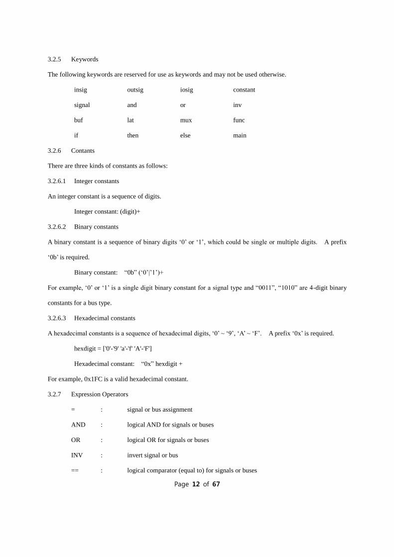
3.2.5 Keywords
The following keywords are reserved for use as keywords and may not be used otherwise.
insig outsig iosig constant
signal and or inv
buf lat mux func
if then else main
3.2.6 Contants
There are three kinds of constants as follows:
3.2.6.1 Integer constants
An integer constant is a sequence of digits.
Integer constant: (digit)+
3.2.6.2 Binary constants
A binary constant is a sequence of binary digits ‘0’ or ‘1’, which could be single or multiple digits. A prefix
‘0b’ is required.
Binary constant: “0b” (‘0’|’1’)+
For example, ‘0’ or ‘1’ is a single digit binary constant for a signal type and “0011”, “1010” are 4-digit binary
constants for a bus type.
3.2.6.3 Hexadecimal constants
A hexadecimal constants is a sequence of hexadecimal digits, ‘0’ ~ ‘9’, ‘A’ ~ ‘F’. A prefix ‘0x’ is required.
hexdigit = ['0'-'9' 'a'-'f' 'A'-'F']
Hexadecimal constant: “0x” hexdigit +
For example, 0x1FC is a valid hexadecimal constant.
3.2.7 Expression Operators
= : signal or bus assignment
AND : logical AND for signals or buses
OR : logical OR for signals or buses
INV : invert signal or bus
== : logical comparator (equal to) for signals or buses

Page 13 of 67
!= : logical comparator (not equal to) for signals or buses
3.2.8 Separators
The following ASC II characters are used as separators:
; : line terminator
[_:_] : bus range specifier
{ } : main or user function definition
, : argument separator
3.3 Data Types
3.3.1 Primitive data types
The following primitive data types are supported in HL-HDL.
3.3.1.1 Integer
An integer type is used to define integral value to the identifier.
3.3.1.2 Signal
A signal type is used to define binary value to the single-bit identifier or multi-digit binary / hexadecimal value
to the multiple-bit identifier.
e.g. foo = 0b1; /* single-bit binary number */
foo[7:0] = 0b11010011; /* 8-bit binary number */
foo[7:0] = 0x5A; /* 8-bit hexadecimal number */
3.3.2 Literals
3.3.2.1 Integer Literals
Integer literal is a sequence of digits and defined as follows:
integer = (digit)+
3.3.2.2 Binary Literals
Single-bit signal literal is a single binary digit or a sequence of binary digits and defined as follows:
Binary = “0b”(‘0’|’1’)+
3.3.2.3 Hexadecimal Literals

Page 14 of 67
Hexadecimal literal is a sequence of hexadecimal digits defined as follows:
hex = [‘0’-‘9’ |’a’-‘f’ ‘A’-‘F’]
Hexadecimal = “0”’ (hex)+
3.4 Expressions
Expressions are evaluated in the order as follows. Also, left- or right-associativity is specified in each
subsection.
3.4.1 Primary expressions
Primary expressions have left-to-right associativity.
3.4.1.1 Identifier
An identifier is a primary expression whose type must be properly declared.
3.4.1.2 Constant
An integer, binary, or hexadecimal constant is a primary expression. Its type is integer, signal, and bus,
respectively.
3.4.1.3 (expression)
A parenthesized expression is a primary expression and its type and value are identical to those of “expression”.
3.4.2 expression1 ( expression2 )
Expression followed by an expression is a part of whole bus signals, where expression1 is bus identifier and
expression2 is in the range of the bus space.
3.4.3 Logical Expressions
The following are the logical expressions and the first two have left-to-right and the last does right-to-left
associativity.
expression1 and expression2 : logical AND
expression1 or expression2 : logical OR
inv (expression) : logical NOT
3.4.4 Numerical Expressions
The following numerical expressions have left-to-right associativity.
expression1 == expression2 : equal to

Page 15 of 67
expression1 != expression2 : not equal to
3.4.5 Assignment Expressions
An assignment expression has right-to-left associativity.
expression1 = expression2
3.4.6 Operator precedence
Precedence Operator type Operators Associativity
1 primary ( ) Left-to-right
2 unary NOT Right-to-left
3 binary AND, OR Left-to-right
4 numerical ==, != Left-to-right
5 assignment = Right-to-left
3.5 Statements
Statements are executed in sequence.
3.5.1 Expression statement
Most expression statements have the form as follows:
expression ;
3.5.2 IF statement
If statement is a conditional statement which has two forms as follows:
optional identifier : if ( expression ) then statement ;
optional identifier : if ( expression ) then statement else statement ;
In both cases, expression is evaluated first and if it is true, the first statement is executed. However, in the
second case, if it is not true, the second statement is executed.
An identifier is required for outer-most if statement for easier translation to VHDL format.
3.6 Functions
There are a couple of generic functions provided in HL-HDL, which are the most generic functional block used
in VHDL. Otherwise, user-defined function can be declared and called. User-defined function can be declared

Page 16 of 67
anywhere in the program.. In regard to mapping to VHDL implementation, it is mapped to “component”
declaration in the VHDL package file.
3.6.1 Generic functions (built-in functions)
The following functions are provided in HL-HDL.
Function_identifier ( parameter list )
3.6.1.1 BUF function
buf (expression): expression is either single or multiple-bit signal and a buffer is added, whose output is the
same type as input expression.
e.g. A = buf(B);
3.6.1.2 INV function
Inv (expression): expression is either single or multiple-bit signal and a inverter is added, whose output is the
same type as input expression.
e.g. A = inv(B);
3.6.1.3 LAT function
lat(reset_identifier, clock_identifier, list of expression ): “reset_identifier” is reset input source to reset the
output of the latch, “clock_identifier” is a clock source for the latch and the list of expressions has input
expression to the latch and the output out of the latch.. Function instantiation identifier is required at the
beginning of the call.
e.g. latch_inst1: lat(rst, clk, LAT_in, LAT_out);
3.6.1.4 4-to-1 MUX function
mux(output_identifier, mux_enable_identifier, SELECT_expression, list of expressions): “output identifier” is
the output assigned out of four inputs. “mux_enable_identifier” is the output enable input which enables the
mux output. When the mux is disabled, its output is tri-stated. “SELECT_expression” is two-bit input to
select one out of four inputs to the mux output. The list of expressions is the 4 inputs to the mux..
e.g. mux_inst1 : mux (mux_output, mux_enable, mux_out_select, mux_input0, , mux_input1, ,
mux_input2, mux_input3);
3.6.2 User-defined function
User-defined function can be declared with a keyword func followed by list of formal parameters in parentheses

Page 17 of 67
and statements in { }.
func identifier (expressions, … , expressions)
{
Statements
}
This corresponds to a COMPONENT declaration in VHDL. It can be instantiated by calling with function
instantiation identifier in main function.
3.6.3 main function
Main function can be declared with a keyword main followed by a list of formal parameters in parentheses and
statements in { }. Main functions constructs top-level entity in VHDL.
main identifier (expressions, … , expressions)
{
Statements
}

Page 18 of 67
4. Project Plan
The project plan for the HL-HDL compiler design was to set up the steps and execute them.
4.1 Project execution steps
At project planning stage, the following steps were set up. Even after one stage was complete, it did not mean
that the corresponding task, mostly coding task, did not freeze, but had to be revisited whenever a bug was
found or new feature had to be added.
Project Specification: After the research for what is appropriate for this project and based on my
experience as a hardware engineer, a language to generate VHDL file were chosen. Main
purpose of the language was to help a hardware designer generate VHDL code from the plain c-
style input code. Due to the time limit on this project, a minimal set of expressions and
statements were picked, which was the major input for the project proposal and the initial draft of
the language reference manual.
Scanner design: Tokens were defined based on the project specification and coded into the scanner.
The initial scanner was tested using simple print function similar to wordcount.ml shown in class
homework 1.
AST and Parser design: All the data types, expressions, and statement structures were coded into
ast.ml and parser.mly as specified. A pretty printer were implemented in ast.ml as helper
functions for debug purpose, which is also added to an option for the compiler (“-a” option).
Translator design: global variables and a list of functions were used as the inputs to the translator.
Each part was decomposed to signals/components in VHDL package and main entity in top-level
VHDL code, respectively. Basic VHDL code structure such as library use clause was added to
the output files. For verification purpose, a sort of helper function was added to generate test
bench template for the top-level entity, so that the user can add their own test bench procedure
easily.
Test program design: Test codes for typical usage of the language, a couple of simple code with

Page 19 of 67
more complicated multi-function code were generated. In order to verify the behavior of the
generated VHDL code, the Modelsim-Altera functional VDHL simulator was chosen as major
simulation tool, since it is easy to get, good for small size simulation, and also free software.
Final Project Report
4.2 Project timeline
Period Description for the tasks
Week 1 ~ Week 4 Research for the project and proposal
Week 5 ~ Week 8
Initial draft of the scanner (scanner.mll) was coded and LRM (Language Refererence
Manual) submitted.
Week 9 ~ Week 12
AST (ast.ml) and Parser (parser.mly) coded and tested with “pretty printer” included
in ast.ml as helper function. Initial main program (hlhdl.ml) was also coded.
Week 13 ~ Week 15
Translator (translate.ml) designed and the generated VDHL files from the source file
was compiled and simulated with Modelsim-Altera VHDL simulator.
Week 16 Final project report.
4.3 Tools used for the project
The following tools were used for the development and testing.
Notepad++: main editing tool
OCAML: compiler language
OcamlWin: supplementary ocaml command test
Cygwin 64-bit terminal: terminal for compiling ocaml source code and execution
Modelsim-Altera: main VHDL simulation tool

Page 20 of 67
5. Architectural Design
5.1 Block Diagram
HL-HDL is composed of the following components shown in the picture below. HHL input file is taken as an
input, then outputs three VHDL files and one text file based on the compilation options. AST (ast.ml) provides
helper functions for pretty printer in translator as well as syntax tree itself. Interface between components is
described in more detail in the following section.
SCANNER
PARSER
TRANSLATOR
HHL input file
TOKENS
AST
Pretty Printer
Top-Level VHDL code
Package VHDL code
Test Bench Template
target.ast Target_top.vhd Target_defs.vhd Target_top_tbframe.vhd
HL-HDL
AST

Page 21 of 67
5.2 Interface between components in the block diagram
5.2.1 Scanner
Scanner takes HHL input file in text format as an input and generates tokens based on the rules set up in
scanner.mll, which is passed to Parser.
5.2.2 Parser
Parser takes tokens from the Scanner and builds an AST based on the parsing rules set up in parser.mly. The
output is not semantically checked AST, which is covered in Translator.
5.2.3 Translator
Translator takes AST from the Parser and process the input list such as global variable and function list in the
following way, and generates output string for the main HLHDL. HLHDL uses one of the following strings to
generate the output file.
(i) Global variables and User-defined functions
Global variables declared in hhl input file are the first part of package called “globals” in the
<filename>_defs.vhd. A header string for VHDL library and use clause is added to the beginning of the
file, too.
User defined function is used to create a string that contains component declaration and the entity with its
architecture body. Typical VHDL libraries are also added to each entity to the beginning of the entity.
This portion of string is also the second part of <filename>_defs.vhd.
(ii) Main function
A top-level entity and its architecture is generated from the main function with the same VHDL libraries
used for package file above. This string is used for top-level vhdl file, <filename>_top.vhd
(iii) Test bench template
VHDL simulation is the most popular way to verify the behavior of the entity generated and requires a test
bench. A header, top-level component declaration, and its instantiation are easily collected from the string
above, which forms a string for the test bench for top-level entity.
(iv) Pretty printer
Pretty printer simply prints out a string that is close to the input file format just for debug purpose.

Page 22 of 67
Usually, this string can be used at the early stage for the verification of the scanner or when new tokens are
added.
5.2.4 HLHDL
HLHDL calls one of the translate functions to let it create a string shown in 5.2.3 and write it to the appropriate
filename. It creates a file, <filename>_top.vhd from the main function string, <filename>_defs.vhd from the
global variables and user-defined functions, <filename>_tbframe.vhd from part of main function string, and
<filename>.ast from AST.

Page 23 of 67
6. Test Plan
In order to verify the generated target program works as designed, a VHDL functional simulation tool,
Modelsim-Altera, was chosen. There are a couple of test programs generated to test the language features and
the output was verified using the simulation tool.
6.1 Test Environment
Two output files, top-level entity and the package file, are fed into the Modelsim-Altera as input VHDL source
files with a test bench source file modified from the test bench template. In addition, a library file
“ lib_comps.vhd“ is provided for simulation. The library file contains two built-in functions such as latch and
4-to-1 mux. One weak point with this tool is, automated testing is not supported due to the tool usage limit.
6.2 Representative source programs and the generated targets
6.2.1 Global constant and main function with built-in function
In this test source program, a couple of global constants were declared which is used in main function. Eight
8-bit data (data_in1[7:0] ~ data_in8[7:0]) are declared as global constants, and one of fist 4 data is selected by
the first 4-to-1 mux and the other from the rest by the second 4-to-1 mux based on two-bit address bus in the
main function.
Filename: test4.hhl /********************************************************************** COMS W4115 PLT - 2014 Spring Term Project HL-HDL compiler: translate.ml Woon Lee (wgl2107) test4.hhl: test case 4 - global constant declaration test based on test case 3

Page 24 of 67
- constants declared are used for 8-to-1 mux input ***********************************************************************/ constant data_in1[7:0] := 0x80; constant data_in2[7:0] := 0x85; constant data_in3[7:0] := 0x8A; constant data_in4[7:0] := 0x8F; constant data_in5[7:0] := 0xC0; constant data_in6[7:0] := 0xC5; constant data_in7[7:0] := 0xCA; constant data_in8[7:0] := 0xCF; main test4(insig clk, insig rst, insig strobe1, insig strobe2, insig addr[2:0], outsig data_out[7:0]) { signal mux1_en; signal mux2_en; mux_ctrl: if (rst == 0b1) then { mux1_en = 0b0; mux2_en = 0b0; } else { if ((strobe1 == 0b1) and (strobe2 == 0b1)) then { mux1_en = inv(addr[2]); mux2_en = addr[2]; } else { mux1_en = 0b0; mux2_en = 0b0; } } /* first 8-bit data 4-to-1 mux */ four_bit_mux1: mux(data_out, mux1_en, addr[1:0], data_in1, data_in2, data_in3, data_in4); /* second 8-bit data 4-to-1 mux */ four_bit_mux2: mux(data_out, mux2_en, addr[1:0], data_in5, data_in6, data_in7, data_in8); }
The following files, test4_top.vhd and test4_defs.vhd, are generated by using “–c” compile option, and test
bench template by using “-t” option.
Filename: test4_top.vhd ---------------------------------------------------- -- COMS W4115 PLT - 2014 Spring Term Project -- HL-HDL compiler -- Woon Lee (wgl2107) ---------------------------------------------------- library IEEE; use IEEE.STD_LOGIC_1164.all; use IEEE.STD_LOGIC_ARITH.ALL; use IEEE.STD_LOGIC_UNSIGNED.ALL; use work.globals.all;

Page 25 of 67
use work.lib_comp.all; ENTITY test4_top is port ( clk : in std_logic; rst : in std_logic; strobe1 : in std_logic; strobe2 : in std_logic; addr : in std_logic_vector(2 downto 0); data_out : out std_logic_vector(7 downto 0) ); end test4_top; architecture RTL of test4_top is signal mux1_en : std_logic; signal mux2_en : std_logic; begin proc_mux_ctrl : process (all) begin if rst = '1' then mux1_en <= '0'; mux2_en <= '0'; else if (strobe1 = '1') AND (strobe2 = '1') then mux1_en <= NOT addr(2); mux2_en <= addr(2); else mux1_en <= '0'; mux2_en <= '0'; end if; end if; end process; four_bit_mux1 : MUX_n_bit generic map(num_bits => 8) port map ( MUX_OUT => data_out, EN => mux1_en, OUT_SEL => addr(1 downto 0), MUX_IN0 => data_in1, MUX_IN1 => data_in2, MUX_IN2 => data_in3, MUX_IN3 => data_in4 ); four_bit_mux2 : MUX_n_bit generic map(num_bits => 8) port map ( MUX_OUT => data_out, EN => mux2_en, OUT_SEL => addr(1 downto 0), MUX_IN0 => data_in5, MUX_IN1 => data_in6, MUX_IN2 => data_in7, MUX_IN3 => data_in8 ); end RTL;

Page 26 of 67
Since the source program has no user-defined functions, there is no corresponding component declaration in this
test case.
Filename: test4_defs.vhd ---------------------------------------------------- -- COMS W4115 PLT - 2014 Spring Term Project -- HL-HDL compiler -- Woon Lee (wgl2107) ---------------------------------------------------- library IEEE; use IEEE.STD_LOGIC_1164.all; use IEEE.STD_LOGIC_ARITH.ALL; use IEEE.STD_LOGIC_UNSIGNED.ALL; package globals is -- Constants and global signals declaration constant data_in1 : std_logic_vector(7 downto 0) := x"80"; constant data_in2 : std_logic_vector(7 downto 0) := x"85"; constant data_in3 : std_logic_vector(7 downto 0) := x"8A"; constant data_in4 : std_logic_vector(7 downto 0) := x"8F"; constant data_in5 : std_logic_vector(7 downto 0) := x"C0"; constant data_in6 : std_logic_vector(7 downto 0) := x"C5"; constant data_in7 : std_logic_vector(7 downto 0) := x"CA"; constant data_in8 : std_logic_vector(7 downto 0) := x"CF"; -- Components declaration end globals; -- Entities and architectures of the components
Filename: test4_top_tbframe.vhd ---------------------------------------------------- -- COMS W4115 PLT - 2014 Spring Term Project -- HL-HDL compiler -- Woon Lee (wgl2107) ---------------------------------------------------- library IEEE; use IEEE.STD_LOGIC_1164.all; use IEEE.STD_LOGIC_ARITH.ALL; use IEEE.STD_LOGIC_UNSIGNED.ALL; use work.globals.all; use work.lib_comp.all; ENTITY test4_top_tb is end ENTITY test4_top_tb; ARCHITECTURE behavioral of test4_top_tb is COMPONENT test4_top is port ( clk : in std_logic; rst : in std_logic;

Page 27 of 67
strobe1 : in std_logic; strobe2 : in std_logic; addr : in std_logic_vector(2 downto 0); data_out : out std_logic_vector(7 downto 0) ); end COMPONENT; signal clk : std_logic; signal rst : std_logic; signal strobe1 : std_logic; signal strobe2 : std_logic; signal addr : std_logic_vector(2 downto 0); signal data_out : std_logic_vector(7 downto 0); begin inst_test4_top : test4_top port map( clk => clk, rst => rst, strobe1 => strobe1, strobe2 => strobe2, addr => addr, data_out => data_out ); end;
The test bench template above is modified and saved to test bench program for simulation as follows.
Different address bits for mux output selection every 75 ns are used for stimulus which resulted in mux output
accordingly.
Filename: test4_top_tb.vhd ---------------------------------------------------- -- COMS W4115 PLT - 2014 Spring Term Project -- HL-HDL compiler -- Woon Lee (wgl2107) ---------------------------------------------------- library IEEE; use IEEE.STD_LOGIC_1164.all; use IEEE.STD_LOGIC_ARITH.ALL; use IEEE.STD_LOGIC_UNSIGNED.ALL; use work.globals.all; use work.lib_comp.all; ENTITY test4_top_tb is end ENTITY test4_top_tb; ARCHITECTURE behavioral of test4_top_tb is COMPONENT test4_top is port (

Page 28 of 67
clk : in std_logic; rst : in std_logic; strobe1 : in std_logic; strobe2 : in std_logic; addr : in std_logic_vector(2 downto 0); data_out : out std_logic_vector(7 downto 0) ); end COMPONENT; signal clk : std_logic; signal rst : std_logic; signal strobe1 : std_logic; signal strobe2 : std_logic; signal addr : std_logic_vector(2 downto 0); signal data_out : std_logic_vector(7 downto 0); signal sim_done : boolean := false; begin inst_test4_top : test4_top port map( clk => clk, rst => rst, strobe1 => strobe1, strobe2 => strobe2, addr => addr, data_out => data_out ); clk_proc : process begin if (not sim_done) then clk <= '0'; wait for 20 ns; clk <= '1'; wait for 20 ns; else report "sim_done"; wait; --wait forever end if; end process clk_proc; input_proc : process begin strobe1 <= '0'; strobe2 <= '0'; wait for 30 ns; strobe1 <= '1'; addr <= "000"; wait for 10 ns; strobe2 <= '1'; wait for 30 ns; strobe1 <= '0'; wait for 5 ns; strobe2 <= '0'; wait for 30 ns; strobe1 <= '1'; addr <= "001"; wait for 10 ns;

Page 29 of 67
strobe2 <= '1'; wait for 30 ns; strobe1 <= '0'; wait for 5 ns; strobe2 <= '0'; wait for 30 ns; strobe1 <= '1'; addr <= "010"; wait for 10 ns; strobe2 <= '1'; wait for 30 ns; strobe1 <= '0'; wait for 5 ns; strobe2 <= '0'; wait for 30 ns; strobe1 <= '1'; addr <= "011"; wait for 10 ns; strobe2 <= '1'; wait for 30 ns; strobe1 <= '0'; wait for 5 ns; strobe2 <= '0'; wait for 30 ns; strobe1 <= '1'; addr <= "100"; wait for 10 ns; strobe2 <= '1'; wait for 30 ns; strobe1 <= '0'; wait for 5 ns; strobe2 <= '0'; wait for 30 ns; strobe1 <= '1'; addr <= "101"; wait for 10 ns; strobe2 <= '1'; wait for 30 ns; strobe1 <= '0'; wait for 5 ns; strobe2 <= '0'; wait for 30 ns; strobe1 <= '1'; addr <= "110"; wait for 10 ns; strobe2 <= '1'; wait for 30 ns; strobe1 <= '0'; wait for 5 ns; strobe2 <= '0'; wait for 30 ns; strobe1 <= '1'; addr <= "111"; wait for 10 ns; strobe2 <= '1';

Page 30 of 67
wait for 30 ns; strobe1 <= '0'; wait for 5 ns; strobe2 <= '0'; wait; end process; sim_time : process begin rst <= '1'; wait for 10 ns; rst <= '0'; wait for 600 ns; sim_done <= true; wait; end process; end;
From the waveform picture below, test result was verified.
6.2.2 Complex program test
Based on simple test cases, this test program covers almost every aspect of the language by implementing global
variables/constants and multiple user-defined functions. Data are written to and read back from 16 registers
represented by 16 global variables. Two user-defined functions, 2-to-4 address decoder and register reader, are
created and controlled from the main function. In the main function, all the built-in functions are instantiated
and single-bit/multiple-bit signals are declared and assigned in the statements.
The source program is shown as follows.
Filename: test6.hhl /************************************************************************************** COMS W4115 PLT - 2014 Spring Term Project HL-HDL compiler: translate.ml Woon Lee (wgl2107) test6.hhl: test case 6

Page 31 of 67
- Complete test suite: covers almost every aspect of HL-HDL ; multiple functions: user-defined and built-in functions ; constants and signals as global variable (set of registers in this test case) ; implement read/write function for 16 registers ***************************************************************************************/ /* Global constants and variables */ constant VERSION[7:0] := 0x10; constant REVISION[7:0] := 0x20; signal REG0[7:0]; signal REG1[7:0]; signal REG2[7:0]; signal REG3[7:0]; signal REG4[7:0]; signal REG5[7:0]; signal REG6[7:0]; signal REG7[7:0]; signal REG8[7:0]; signal REG9[7:0]; signal REG10[7:0]; signal REG11[7:0]; signal REG12[7:0]; signal REG13[7:0]; signal REG14[7:0]; signal REG15[7:0]; /* two-bit input is decoded into four strobes */ func decode_2_to_4(insig rst, insig strb_in, insig in_2bit[1:0], outsig strb_out[3:0]) { rst_cond: if (rst == 0b1) then { strb_out = 0x0; } else { if (in_2bit == 0b00) then { strb_out[0] = strb_in; strb_out[3:1] = 0b000; } else if (in_2bit == 0b01) then { strb_out[0] = 0b0; strb_out[1] = strb_in; strb_out[3:2] = 0b00; } else if (in_2bit == 0b10) then { strb_out[1:0] = 0b00; strb_out[2] = strb_in; strb_out[3] = 0b0; } else { strb_out[2:0] = 0b000; strb_out[3] = strb_in; } } } /* Register READ: 16-to-1 8-bit-wide data mux using 4 mux functions */ func reg_read(insig rst, insig strb_in, insig addr_in[3:0], outsig data_out[7:0]) { signal bank_en[3:0]; /* 4 enable strobes for 4-to-1 MUX generation using upper 2 addr_in bits */ bank_sel: decode_2_to_4(rst, strb_in, addr_in[3:2], bank_en);

Page 32 of 67
first_bank: mux(data_out, bank_en[0], addr_in[1:0], REG0, REG1, REG2, REG3); second_bank: mux(data_out, bank_en[1], addr_in[1:0], REG4, REG5, REG6, REG7); third_bank: mux(data_out, bank_en[2], addr_in[1:0], REG8, REG9, REG10, REG11); fourth_bank: mux(data_out, bank_en[3], addr_in[1:0], REG12, REG13, REG14, REG15); } main test6(insig clk, insig rst, insig csn, insig oen, insig wrn, insig addr[3:0], iosig data[7:0]) { signal chip_sel; signal rd_en; signal rd_strb; signal rd_strb_latched; signal wr_en; signal wr_strb; signal wr_strb_latched; signal addr_latched[3:0]; signal datain[7:0]; signal dataout[7:0]; signal reg_sel_strb[15:0]; signal reg_bank_sel[3:0]; /* Initialize the first two registers */ REG0 = VERSION; REG1 = REVISION; /* invert active-low input signals to active-high ones */ chip_sel = inv(csn); rd_en = inv(oen); rd_strb = chip_sel and rd_en; wr_en = inv(wrn); wr_strb = chip_sel and wr_en; /* make the strobes synchronous to the clk */ latch_rd: lat(rst, 0b1, clk, rd_strb, rd_strb_latched); latch_wr: lat(rst, 0b1, clk, wr_strb, wr_strb_latched); latch_addr: lat(rst, 0b1, clk, addr, addr_latched); latch_datain: lat(rst, wr_strb, clk, data, datain); /* Register read */ inst_cpu_read: reg_read(rst, rd_strb_latched, addr_latched, dataout); data = dataout; /* Register write */ four_bank_sel: decode_2_to_4(rst, wr_strb_latched, addr_latched[3:2], reg_bank_sel); first_bank_strobes: decode_2_to_4(rst, reg_bank_sel[0], addr_latched[1:0], reg_sel_strb[3:0]); second_bank_strobes: decode_2_to_4(rst, reg_bank_sel[1], addr_latched[1:0], reg_sel_strb[7:4]); third_bank_strobes: decode_2_to_4(rst, reg_bank_sel[2], addr_latched[1:0], reg_sel_strb[11:8]); fourth_bank_strobes: decode_2_to_4(rst, reg_bank_sel[3], addr_latched[1:0], reg_sel_strb[15:12]); /* write the data to the selected Register on reg_sel_strb */ /* The first two registers are read-only */ /* data_write_reg0: lat(rst, reg_sel_strb[0], clk, datain, REG0); data_write_reg1: lat(rst, reg_sel_strb[1], clk, datain, REG1); */ data_write_reg2: lat(rst, reg_sel_strb[2], clk, datain, REG2); data_write_reg3: lat(rst, reg_sel_strb[3], clk, datain, REG3); data_write_reg4: lat(rst, reg_sel_strb[4], clk, datain, REG4); data_write_reg5: lat(rst, reg_sel_strb[5], clk, datain, REG5); data_write_reg6: lat(rst, reg_sel_strb[6], clk, datain, REG6); data_write_reg7: lat(rst, reg_sel_strb[7], clk, datain, REG7); data_write_reg8: lat(rst, reg_sel_strb[8], clk, datain, REG8);

Page 33 of 67
data_write_reg9: lat(rst, reg_sel_strb[9], clk, datain, REG9); data_write_reg10: lat(rst, reg_sel_strb[10], clk, datain, REG10); data_write_reg11: lat(rst, reg_sel_strb[11], clk, datain, REG11); data_write_reg12: lat(rst, reg_sel_strb[12], clk, datain, REG12); data_write_reg13: lat(rst, reg_sel_strb[13], clk, datain, REG13); data_write_reg14: lat(rst, reg_sel_strb[14], clk, datain, REG14); data_write_reg15: lat(rst, reg_sel_strb[15], clk, datain, REG15); }
The following file shows top-level entity generated from the main function.
Filename: test6_top.vhd ---------------------------------------------------- -- COMS W4115 PLT - 2014 Spring Term Project -- HL-HDL compiler -- Woon Lee (wgl2107) ---------------------------------------------------- library IEEE; use IEEE.STD_LOGIC_1164.all; use IEEE.STD_LOGIC_ARITH.ALL; use IEEE.STD_LOGIC_UNSIGNED.ALL; use work.globals.all; use work.lib_comp.all; ENTITY test6_top is port ( clk : in std_logic; rst : in std_logic; csn : in std_logic; oen : in std_logic; wrn : in std_logic; addr : in std_logic_vector(3 downto 0); data : inout std_logic_vector(7 downto 0) ); end test6_top; architecture RTL of test6_top is signal chip_sel : std_logic; signal rd_en : std_logic; signal rd_strb : std_logic; signal rd_strb_latched : std_logic; signal wr_en : std_logic; signal wr_strb : std_logic; signal wr_strb_latched : std_logic; signal addr_latched : std_logic_vector(3 downto 0); signal datain : std_logic_vector(7 downto 0); signal dataout : std_logic_vector(7 downto 0); signal reg_sel_strb : std_logic_vector(15 downto 0); signal reg_bank_sel : std_logic_vector(3 downto 0); begin REG0 <= VERSION; REG1 <= REVISION; chip_sel <= NOT csn; rd_en <= NOT oen;

Page 34 of 67
rd_strb <= chip_sel AND rd_en; wr_en <= NOT wrn; wr_strb <= chip_sel AND wr_en; latch_rd : LATCH port map ( RST => rst, EN => '1', CLK => clk, LAT_IN => rd_strb, LAT_OUT => rd_strb_latched ); latch_wr : LATCH port map ( RST => rst, EN => '1', CLK => clk, LAT_IN => wr_strb, LAT_OUT => wr_strb_latched ); latch_addr : LATCH_n_bit generic map(num_bits => 4) port map ( RST => rst, EN => '1', CLK => clk, LAT_IN => addr, LAT_OUT => addr_latched ); latch_datain : LATCH_n_bit generic map(num_bits => 8) port map ( RST => rst, EN => wr_strb, CLK => clk, LAT_IN => data, LAT_OUT => datain ); inst_cpu_read_reg_read : reg_read port map ( rst => rst, strb_in => rd_strb_latched, addr_in => addr_latched, data_out => dataout ); data <= dataout; four_bank_sel_decode_2_to_4 : decode_2_to_4 port map ( rst => rst, strb_in => wr_strb_latched, in_2bit => addr_latched(3 downto 2), strb_out => reg_bank_sel ); first_bank_strobes_decode_2_to_4 : decode_2_to_4 port map ( rst => rst, strb_in => reg_bank_sel(0), in_2bit => addr_latched(1 downto 0), strb_out => reg_sel_strb(3 downto 0) ); second_bank_strobes_decode_2_to_4 : decode_2_to_4 port map ( rst => rst, strb_in => reg_bank_sel(1),

Page 35 of 67
in_2bit => addr_latched(1 downto 0), strb_out => reg_sel_strb(7 downto 4) ); third_bank_strobes_decode_2_to_4 : decode_2_to_4 port map ( rst => rst, strb_in => reg_bank_sel(2), in_2bit => addr_latched(1 downto 0), strb_out => reg_sel_strb(11 downto 8) ); fourth_bank_strobes_decode_2_to_4 : decode_2_to_4 port map ( rst => rst, strb_in => reg_bank_sel(3), in_2bit => addr_latched(1 downto 0), strb_out => reg_sel_strb(15 downto 12) ); data_write_reg2 : LATCH_n_bit generic map(num_bits => 8) port map ( RST => rst, EN => reg_sel_strb(2), CLK => clk, LAT_IN => datain, LAT_OUT => REG2 ); data_write_reg3 : LATCH_n_bit generic map(num_bits => 8) port map ( RST => rst, EN => reg_sel_strb(3), CLK => clk, LAT_IN => datain, LAT_OUT => REG3 ); data_write_reg4 : LATCH_n_bit generic map(num_bits => 8) port map ( RST => rst, EN => reg_sel_strb(4), CLK => clk, LAT_IN => datain, LAT_OUT => REG4 ); data_write_reg5 : LATCH_n_bit generic map(num_bits => 8) port map ( RST => rst, EN => reg_sel_strb(5), CLK => clk, LAT_IN => datain, LAT_OUT => REG5 ); data_write_reg6 : LATCH_n_bit generic map(num_bits => 8) port map ( RST => rst, EN => reg_sel_strb(6),

Page 36 of 67
CLK => clk, LAT_IN => datain, LAT_OUT => REG6 ); data_write_reg7 : LATCH_n_bit generic map(num_bits => 8) port map ( RST => rst, EN => reg_sel_strb(7), CLK => clk, LAT_IN => datain, LAT_OUT => REG7 ); data_write_reg8 : LATCH_n_bit generic map(num_bits => 8) port map ( RST => rst, EN => reg_sel_strb(8), CLK => clk, LAT_IN => datain, LAT_OUT => REG8 ); data_write_reg9 : LATCH_n_bit generic map(num_bits => 8) port map ( RST => rst, EN => reg_sel_strb(9), CLK => clk, LAT_IN => datain, LAT_OUT => REG9 ); data_write_reg10 : LATCH_n_bit generic map(num_bits => 8) port map ( RST => rst, EN => reg_sel_strb(10), CLK => clk, LAT_IN => datain, LAT_OUT => REG10 ); data_write_reg11 : LATCH_n_bit generic map(num_bits => 8) port map ( RST => rst, EN => reg_sel_strb(11), CLK => clk, LAT_IN => datain, LAT_OUT => REG11 ); data_write_reg12 : LATCH_n_bit generic map(num_bits => 8) port map ( RST => rst, EN => reg_sel_strb(12), CLK => clk,

Page 37 of 67
LAT_IN => datain, LAT_OUT => REG12 ); data_write_reg13 : LATCH_n_bit generic map(num_bits => 8) port map ( RST => rst, EN => reg_sel_strb(13), CLK => clk, LAT_IN => datain, LAT_OUT => REG13 ); data_write_reg14 : LATCH_n_bit generic map(num_bits => 8) port map ( RST => rst, EN => reg_sel_strb(14), CLK => clk, LAT_IN => datain, LAT_OUT => REG14 ); data_write_reg15 : LATCH_n_bit generic map(num_bits => 8) port map ( RST => rst, EN => reg_sel_strb(15), CLK => clk, LAT_IN => datain, LAT_OUT => REG15 ); end RTL;
From the global variables and user-defined functions, package file is generated as below.
Filename: test6_defs.vhd ---------------------------------------------------- -- COMS W4115 PLT - 2014 Spring Term Project -- HL-HDL compiler -- Woon Lee (wgl2107) ---------------------------------------------------- library IEEE; use IEEE.STD_LOGIC_1164.all; use IEEE.STD_LOGIC_ARITH.ALL; use IEEE.STD_LOGIC_UNSIGNED.ALL; package globals is -- Constants and global signals declaration constant VERSION : std_logic_vector(7 downto 0) := x"10"; constant REVISION : std_logic_vector(7 downto 0) := x"20"; signal REG0 : std_logic_vector(7 downto 0); signal REG1 : std_logic_vector(7 downto 0); signal REG2 : std_logic_vector(7 downto 0); signal REG3 : std_logic_vector(7 downto 0);

Page 38 of 67
signal REG4 : std_logic_vector(7 downto 0); signal REG5 : std_logic_vector(7 downto 0); signal REG6 : std_logic_vector(7 downto 0); signal REG7 : std_logic_vector(7 downto 0); signal REG8 : std_logic_vector(7 downto 0); signal REG9 : std_logic_vector(7 downto 0); signal REG10 : std_logic_vector(7 downto 0); signal REG11 : std_logic_vector(7 downto 0); signal REG12 : std_logic_vector(7 downto 0); signal REG13 : std_logic_vector(7 downto 0); signal REG14 : std_logic_vector(7 downto 0); signal REG15 : std_logic_vector(7 downto 0); -- Components declaration component decode_2_to_4 is port ( rst : in std_logic; strb_in : in std_logic; in_2bit : in std_logic_vector(1 downto 0); strb_out : out std_logic_vector(3 downto 0) ); end component decode_2_to_4; component reg_read is port ( rst : in std_logic; strb_in : in std_logic; addr_in : in std_logic_vector(3 downto 0); data_out : out std_logic_vector(7 downto 0) ); end component reg_read; end globals; -- Entities and architectures of the components library IEEE; use IEEE.STD_LOGIC_1164.all; use IEEE.STD_LOGIC_ARITH.ALL; use IEEE.STD_LOGIC_UNSIGNED.ALL; use work.globals.all; use work.lib_comp.all; ENTITY decode_2_to_4 is port ( rst : in std_logic; strb_in : in std_logic; in_2bit : in std_logic_vector(1 downto 0); strb_out : out std_logic_vector(3 downto 0) ); end decode_2_to_4; architecture RTL of decode_2_to_4 is begin proc_rst_cond : process (all) begin if rst = '1' then strb_out <= x"0"; else if in_2bit = "00" then

Page 39 of 67
strb_out(0) <= strb_in; strb_out(3 downto 1) <= "000"; else if in_2bit = "01" then strb_out(0) <= '0'; strb_out(1) <= strb_in; strb_out(3 downto 2) <= "00"; else if in_2bit = "10" then strb_out(1 downto 0) <= "00"; strb_out(2) <= strb_in; strb_out(3) <= '0'; else strb_out(2 downto 0) <= "000"; strb_out(3) <= strb_in; end if; end if; end if; end if; end process; end RTL; configuration CFG_decode_2_to_4 of decode_2_to_4 is for RTL end for; end CFG_decode_2_to_4; library IEEE; use IEEE.STD_LOGIC_1164.all; use IEEE.STD_LOGIC_ARITH.ALL; use IEEE.STD_LOGIC_UNSIGNED.ALL; use work.globals.all; use work.lib_comp.all; ENTITY reg_read is port ( rst : in std_logic; strb_in : in std_logic; addr_in : in std_logic_vector(3 downto 0); data_out : out std_logic_vector(7 downto 0) ); end reg_read; architecture RTL of reg_read is signal bank_en : std_logic_vector(3 downto 0); begin bank_sel_decode_2_to_4 : decode_2_to_4 port map ( rst => rst, strb_in => strb_in, in_2bit => addr_in(3 downto 2), strb_out => bank_en ); first_bank : MUX_n_bit generic map(num_bits => 8) port map ( MUX_OUT => data_out, EN => bank_en(0), OUT_SEL => addr_in(1 downto 0), MUX_IN0 => REG0,

Page 40 of 67
MUX_IN1 => REG1, MUX_IN2 => REG2, MUX_IN3 => REG3 ); second_bank : MUX_n_bit generic map(num_bits => 8) port map ( MUX_OUT => data_out, EN => bank_en(1), OUT_SEL => addr_in(1 downto 0), MUX_IN0 => REG4, MUX_IN1 => REG5, MUX_IN2 => REG6, MUX_IN3 => REG7 ); third_bank : MUX_n_bit generic map(num_bits => 8) port map ( MUX_OUT => data_out, EN => bank_en(2), OUT_SEL => addr_in(1 downto 0), MUX_IN0 => REG8, MUX_IN1 => REG9, MUX_IN2 => REG10, MUX_IN3 => REG11 ); fourth_bank : MUX_n_bit generic map(num_bits => 8) port map ( MUX_OUT => data_out, EN => bank_en(3), OUT_SEL => addr_in(1 downto 0), MUX_IN0 => REG12, MUX_IN1 => REG13, MUX_IN2 => REG14, MUX_IN3 => REG15 ); end RTL; configuration CFG_reg_read of reg_read is for RTL end for; end CFG_reg_read;
This file is the test bench template which is followed by the edited test bench program.
Filename: test6_top_tbframe.vhd ---------------------------------------------------- -- COMS W4115 PLT - 2014 Spring Term Project -- HL-HDL compiler -- Woon Lee (wgl2107) ---------------------------------------------------- library IEEE; use IEEE.STD_LOGIC_1164.all;

Page 41 of 67
use IEEE.STD_LOGIC_ARITH.ALL; use IEEE.STD_LOGIC_UNSIGNED.ALL; use work.globals.all; use work.lib_comp.all; ENTITY test6_top_tb is end ENTITY test6_top_tb; ARCHITECTURE behavioral of test6_top_tb is COMPONENT test6_top is port ( clk : in std_logic; rst : in std_logic; csn : in std_logic; oen : in std_logic; wrn : in std_logic; addr : in std_logic_vector(3 downto 0); data : inout std_logic_vector(7 downto 0) ); end COMPONENT; signal clk : std_logic; signal rst : std_logic; signal csn : std_logic; signal oen : std_logic; signal wrn : std_logic; signal addr : std_logic_vector(3 downto 0); signal data : std_logic_vector(7 downto 0); begin inst_test6_top : test6_top port map( clk => clk, rst => rst, csn => csn, oen => oen, wrn => wrn, addr => addr, data => data ); end;
Filename: test6_top_tb.vhd ---------------------------------------------------- -- COMS W4115 PLT - 2014 Spring Term Project -- HL-HDL compiler -- Woon Lee (wgl2107) ---------------------------------------------------- library IEEE; use IEEE.STD_LOGIC_1164.all;

Page 42 of 67
use IEEE.STD_LOGIC_ARITH.ALL; use IEEE.STD_LOGIC_UNSIGNED.ALL; use work.globals.all; use work.lib_comp.all; ENTITY test6_top_tb is end ENTITY test6_top_tb; ARCHITECTURE behavioral of test6_top_tb is procedure RegRd ( signal cs_n : out std_logic; signal read_n : out std_logic; signal write_n : out std_logic; signal reg_addr : in std_logic_vector(3 downto 0); signal addr_out : out std_logic_vector(3 downto 0) ) is begin cs_n <= '1'; read_n <= '1'; write_n <= '1'; wait for 30 ns; addr_out <= reg_addr; wait for 5 ns; cs_n <= '0'; wait for 5 ns; read_n <= '0'; -- read access wait for 60 ns; read_n <= '1'; wait for 5 ns; cs_n <= '1'; wait for 20 ns; end procedure; procedure RegWr ( signal cs_n : out std_logic; signal read_n : out std_logic; signal write_n : out std_logic; signal reg_addr : in std_logic_vector(3 downto 0); signal addr_out : out std_logic_vector(3 downto 0); signal data_in : in std_logic_vector(7 downto 0); signal data_out : out std_logic_vector(7 downto 0) ) is begin cs_n <= '1'; read_n <= '1'; write_n <= '1'; wait for 30 ns; addr_out <= reg_addr; wait for 5 ns; cs_n <= '0'; data_out <= data_in; wait for 5 ns; write_n <= '0'; -- read access

Page 43 of 67
wait for 60 ns; write_n <= '1'; wait for 5 ns; cs_n <= '1'; data_out <= (others => 'Z'); wait for 20 ns; end procedure; COMPONENT test6_top is port ( clk : in std_logic; rst : in std_logic; csn : in std_logic; oen : in std_logic; wrn : in std_logic; addr : in std_logic_vector(3 downto 0); data : inout std_logic_vector(7 downto 0) ); end COMPONENT; signal clk : std_logic; signal rst : std_logic; signal csn : std_logic; signal oen : std_logic; signal wrn : std_logic; signal addr : std_logic_vector(3 downto 0); signal data : std_logic_vector(7 downto 0); signal register_addr : std_logic_vector(3 downto 0); signal wr_value : std_logic_vector(7 downto 0); signal sim_done : boolean := false; begin inst_test6_top : test6_top port map( clk => clk, rst => rst, csn => csn, oen => oen, wrn => wrn, addr => addr, data => data ); clk_proc : process begin if (not sim_done) then clk <= '0'; wait for 10 ns; clk <= '1'; wait for 10 ns; else report "sim_done"; wait; --wait forever end if; end process clk_proc; reg_rd_wr_seq : process begin data <= (others => 'Z'); wait for 30 ns;

Page 44 of 67
-- check version and revision register_addr <= x"0"; RegRd(csn, oen, wrn, register_addr, addr); register_addr <= x"1"; RegRd(csn, oen, wrn, register_addr, addr); -- write all 14 registers with unique values, respectively register_addr <= x"2"; wr_value <= x"22"; RegWr(csn, oen, wrn, register_addr, addr, wr_value, data); register_addr <= x"3"; wr_value <= x"33"; RegWr(csn, oen, wrn, register_addr, addr, wr_value, data); register_addr <= x"4"; wr_value <= x"44"; RegWr(csn, oen, wrn, register_addr, addr, wr_value, data); register_addr <= x"5"; wr_value <= x"55"; RegWr(csn, oen, wrn, register_addr, addr, wr_value, data); register_addr <= x"6"; wr_value <= x"66"; RegWr(csn, oen, wrn, register_addr, addr, wr_value, data); register_addr <= x"7"; wr_value <= x"77"; RegWr(csn, oen, wrn, register_addr, addr, wr_value, data); register_addr <= x"8"; wr_value <= x"88"; RegWr(csn, oen, wrn, register_addr, addr, wr_value, data); register_addr <= x"9"; wr_value <= x"99"; RegWr(csn, oen, wrn, register_addr, addr, wr_value, data); register_addr <= x"A"; wr_value <= x"AA"; RegWr(csn, oen, wrn, register_addr, addr, wr_value, data); register_addr <= x"B"; wr_value <= x"BB"; RegWr(csn, oen, wrn, register_addr, addr, wr_value, data); register_addr <= x"C"; wr_value <= x"CC"; RegWr(csn, oen, wrn, register_addr, addr, wr_value, data); register_addr <= x"D"; wr_value <= x"DD"; RegWr(csn, oen, wrn, register_addr, addr, wr_value, data); register_addr <= x"E"; wr_value <= x"EE"; RegWr(csn, oen, wrn, register_addr, addr, wr_value, data); register_addr <= x"F"; wr_value <= x"FF"; RegWr(csn, oen, wrn, register_addr, addr, wr_value, data); -- read back register values and verify register_addr <= x"0"; RegRd(csn, oen, wrn, register_addr, addr); register_addr <= x"1"; RegRd(csn, oen, wrn, register_addr, addr); register_addr <= x"2"; RegRd(csn, oen, wrn, register_addr, addr); register_addr <= x"3"; RegRd(csn, oen, wrn, register_addr, addr); register_addr <= x"4"; RegRd(csn, oen, wrn, register_addr, addr); register_addr <= x"5"; RegRd(csn, oen, wrn, register_addr, addr); register_addr <= x"6"; RegRd(csn, oen, wrn, register_addr, addr); register_addr <= x"7"; RegRd(csn, oen, wrn, register_addr, addr); register_addr <= x"8"; RegRd(csn, oen, wrn, register_addr, addr); register_addr <= x"9"; RegRd(csn, oen, wrn, register_addr, addr); register_addr <= x"A"; RegRd(csn, oen, wrn, register_addr, addr); register_addr <= x"B"; RegRd(csn, oen, wrn, register_addr, addr); register_addr <= x"C"; RegRd(csn, oen, wrn, register_addr, addr); register_addr <= x"D"; RegRd(csn, oen, wrn, register_addr, addr); register_addr <= x"E"; RegRd(csn, oen, wrn, register_addr, addr); register_addr <= x"F"; RegRd(csn, oen, wrn, register_addr, addr); -- write different values to selected registers register_addr <= x"2"; wr_value <= x"E8"; RegWr(csn, oen, wrn, register_addr, addr, wr_value, data); register_addr <= x"7"; wr_value <= x"5A"; RegWr(csn, oen, wrn, register_addr, addr, wr_value, data); register_addr <= x"C"; wr_value <= x"A5"; RegWr(csn, oen, wrn, register_addr, addr, wr_value, data); -- read back and verify register_addr <= x"2"; RegRd(csn, oen, wrn, register_addr, addr); register_addr <= x"7"; RegRd(csn, oen, wrn, register_addr, addr); register_addr <= x"C"; RegRd(csn, oen, wrn, register_addr, addr);

Page 45 of 67
wait; end process; sim_time : process begin rst <= '1'; wait for 10 ns; rst <= '0'; wait for 5000 ns; sim_done <= true; wait; end process; end;
Finally, the waveform was reported by the simulator.

Page 46 of 67
6.3 Test Suites
The following table shows the test suites with description of the test target.
Test Case Input file Output files Description
1
test1.hhl test1_top.vhd test1_defs.vhd test1_top_tbframe.vhd
Simple built-in function and bit opeator test:
- buf, inv, and, or
2
test2.hhl test2_top.vhd test2_defs.vhd test2_top_tbframe.vhd
Two built-in function test:
- lat, mux for single-bit and multiple-bit signals
3
test3.hhl test3_top.vhd test3_defs.vhd test3_top_tbframe.vhd
More complex main function:
- implementing 8-to-1 mux using built-in 4-to-1 mux
- if statement with comparison operator tested.
4
test4.hhl test4_top.vhd test4_defs.vhd test4_top_tbframe.vhd
Global constant test based on test case 3. See section
6.2.1 for more detail.
5
test5.hhl test5_top.vhd test5_defs.vhd test5_top_tbframe.vhd
User-defined function implementation test:
- One user function declared and called up in the
main function
- The corresponding component declaration and
entity are added to test5_defs.vhd
6
test6.hhl test6_top.vhd test6_defs.vhd test6_top_tbframe.vhd
This covers almost every aspect of the language by
implementing global variables/constants and multiple
user-defined functions. See section 6.2.2 for moe
detail.

Page 47 of 67
7. Lessons Learned
7.1 Importance of specification
As an experienced VHDL designer, it was thought to be easier to design a language that translates a source
program into VHDL format. It led me to not pay attention to what can be or cannot be implemented, which
made me modify the language specification back and forth as the compiler design phase passed. Modification
of the specification is not always bad, but if it requires structural changes, it cost much more than expected. It
was a good lesson that clear definition and specification at early design phase is most important task in design
process.
7.2 Understanding of the Implementation Language
As a novice on OCAML, I was amazed to know how great this language is in terms of data type handling,
concise grammar even though it was hard to understand at the beginning, and overall language structure. As
aforementioned, I had to spend much time on getting the OCAML concept and its unique way of realization
through the example codes. Once I got used to it, it was a lot easier to use the language features in
implementation. If I had more understanding on it, it would have taken less time for this language design and
allowed me to add more complicated features
7.3 Time Management
This would the most expressed cliché, “start earlier as possible and spend more time on verification”, that hit me
once again. Struggling with implementation, debugging took most of the project time and therefore there were
less time for tests. I could have worked on wider test suites and more automated design process.

Page 48 of 67
8. References
[1] The Ocaml reference manual, http://caml.inria.fr/pub/docs/manual-ocaml-4.01/index.html
[2] The Designer's Guide to VHDL, Third Edition (Systems on Silicon) by Peter J. Ashenden (May 29, 2008)
[3] The MicroC compiler, http://www.cs.columbia.edu/~sedwards/classes/2014/w4115-spring/microc.pdf
[4] Simple Image Processing Language (SIP) Final Report,
http://www.cs.columbia.edu/~sedwards/classes/2013/w4115-summer/reports/SIP.pdf
[5] The Quartus II handbook Ver 13.1, Volume3: Verification,
http://www.altera.com/literature/hb/qts/qts_qii5v3.pdf

Page 49 of 67
9. Appendix
< scanner.mll >

Page 50 of 67
< parser.mly >

Page 51 of 67

Page 52 of 67

Page 53 of 67
< ast.ml >

Page 54 of 67

Page 55 of 67

Page 56 of 67
< translate.ml >

Page 57 of 67

Page 58 of 67

Page 59 of 67

Page 60 of 67

Page 61 of 67

Page 62 of 67

Page 63 of 67

Page 64 of 67

Page 65 of 67
< hlhdl.ml >

Page 66 of 67

Page 67 of 67
< Makefile >