hk860 - auto kellydiesel.autokelly.cz/.../11/hk860...eui_vstrikovace.pdf · hk860 cummins eui...
TRANSCRIPT
HL020 08/02
World Leaders in Diesel Fuel Injection Test Equipment
HK860
CUMMINS EUI INJECTOR TEST KIT
(For HA290 Test Stand)
Installation and Operation Manual
THIS IS AN UNCONTROLLED DOCUMENT downloaded by Lukas Matuska on 16 Feb 2016Any technical intervention requires certified Hartridge training. Contact Hartridge Ltd for details.

THIS IS AN UNCONTROLLED DOCUMENT downloaded by Lukas Matuska on 16 Feb 2016Any technical intervention requires certified Hartridge training. Contact Hartridge Ltd for details.
HARTRIDGE LIMITED HK860 OPERATING MANUAL
HL020 08/02 1
CONTENTS
1. SAFETY INFORMATION 3
2. INTRODUCTION AND SPECIFICATION 7 2.1. OVERVIEW 7 2.2. SPECIFICATION 7
2.2.1 Controls 7 2.2.2 Indicators 10 2.2.3 Power Input 10 2.2.4 Output 10 2.2.5 Protection 10
3. INSTALLATION 11 3.1. ELECTRICAL 11 3.2. MECHANICAL 13
3.2.1 Fuel Arm Modification 13 3.2.2 Control Valve Modification 13 3.2.3 Deadweight Modification 14 3.2.4 Nose Cone Assembly Modification 15 3.2.5 Injector Guard Modification 16
4. OPERATION 17 4.1. OPERATING PRINCIPLES 17 4.2. OPERATING PROCEDURE 17
5. MAINTENANCE 18
6. APPENDIX A – CONTROL VALVE ASSEMBLY 20
7. APPENDIX B – NOSE CONE ASSEMBLY 22
8. APPENDIX C – GUARD MODIFICATION 24
9. APPENDIX D – TIMING DIAGRAM 26
10. APPENDIX E – INJECTOR ACCESSORIES 28
THIS IS AN UNCONTROLLED DOCUMENT downloaded by Lukas Matuska on 16 Feb 2016Any technical intervention requires certified Hartridge training. Contact Hartridge Ltd for details.

HK860 OPERATING MANUAL HARTRIDGE LIMITED
2 HL020 08/02
This page is deliberately left blank
THIS IS AN UNCONTROLLED DOCUMENT downloaded by Lukas Matuska on 16 Feb 2016Any technical intervention requires certified Hartridge training. Contact Hartridge Ltd for details.

HARTRIDGE LIMITED HK860 OPERATING MANUAL
HL020 08/02 3
1. SAFETY INFORMATION Most accidents involving equipment operation and maintenance are caused by failure to observe basic safety rules or precautions. An accident can often be avoided by recognising potentially hazardous situations beforehand. The equipment is designed to be intrinsically safe whenever possible. Guards are fitted to afford optimum operator protection.
Read and understand all warning, caution, prohibition and mandatory notices and labels on the equipment before operation or carrying out any maintenance or servicing.
If in doubt - ASK!
Warnings, Cautions and Notes The precautionary notes in this publication, indicated by the words WARNING, CAUTION, or NOTE provide information about potential hazards to personnel or equipment. Ignoring these notes may lead to serious injury to personnel and/or damage to equipment. These notes appear as follows:
WARNING! INDICATES THAT A SITUATION MAY BE HAZARDOUS TO PERSONNEL. INSTRUCTIONS ARE PROVIDED FOR AVOIDING PERSONAL INJURY.
CAUTION! Indicates that conditions exist that could result in damage to equipment. Instructions are provided to prevent equipment damage.
NOTE: Indicates additional information for clarification where there may be confusion.
Warning Symbols
Isolate the electrical supply before performing any maintenance operations. Do not work on electrical equipment while voltage is supplied. If such cannot be avoided, e.g. for measurements, tests or adjustments, have the action carried out by qualified personnel only.
Safety glasses must be worn when working on this equipment for the following reasons:
1.The test equipment is capable of producing high pressure fluid jets or sprays which can cause severe eye injury in the event of a malfunction.
2.The test stand uses calibration fluid which is harmful to the eyes.
THIS IS AN UNCONTROLLED DOCUMENT downloaded by Lukas Matuska on 16 Feb 2016Any technical intervention requires certified Hartridge training. Contact Hartridge Ltd for details.
HK860 OPERATING MANUAL HARTRIDGE LIMITED
4 HL020 08/02
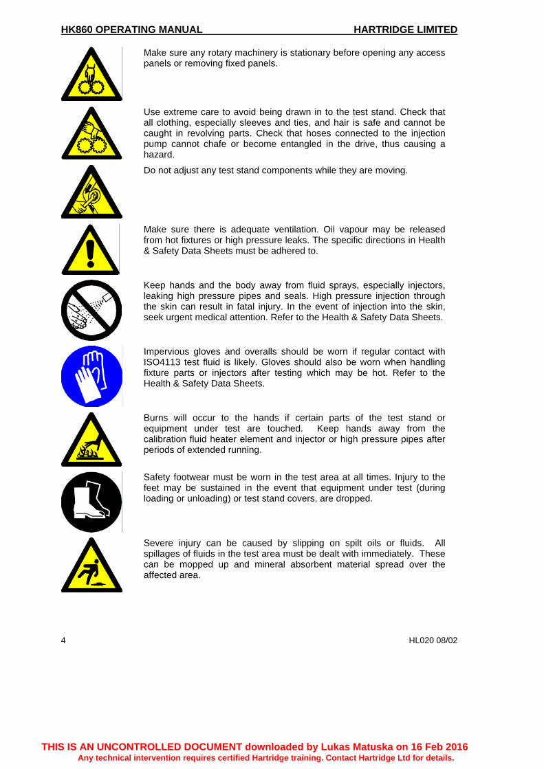
Make sure any rotary machinery is stationary before opening any access panels or removing fixed panels.
Use extreme care to avoid being drawn in to the test stand. Check that all clothing, especially sleeves and ties, and hair is safe and cannot be caught in revolving parts. Check that hoses connected to the injection pump cannot chafe or become entangled in the drive, thus causing a hazard.
Do not adjust any test stand components while they are moving.
Make sure there is adequate ventilation. Oil vapour may be released from hot fixtures or high pressure leaks. The specific directions in Health & Safety Data Sheets must be adhered to.
Keep hands and the body away from fluid sprays, especially injectors, leaking high pressure pipes and seals. High pressure injection through the skin can result in fatal injury. In the event of injection into the skin, seek urgent medical attention. Refer to the Health & Safety Data Sheets.
Impervious gloves and overalls should be worn if regular contact with ISO4113 test fluid is likely. Gloves should also be worn when handling fixture parts or injectors after testing which may be hot. Refer to the Health & Safety Data Sheets.
Burns will occur to the hands if certain parts of the test stand or equipment under test are touched. Keep hands away from the calibration fluid heater element and injector or high pressure pipes after periods of extended running.
Safety footwear must be worn in the test area at all times. Injury to the feet may be sustained in the event that equipment under test (during loading or unloading) or test stand covers, are dropped.
Severe injury can be caused by slipping on spilt oils or fluids. All spillages of fluids in the test area must be dealt with immediately. These can be mopped up and mineral absorbent material spread over the affected area.
THIS IS AN UNCONTROLLED DOCUMENT downloaded by Lukas Matuska on 16 Feb 2016Any technical intervention requires certified Hartridge training. Contact Hartridge Ltd for details.

HARTRIDGE LIMITED HK860 OPERATING MANUAL
HL020 08/02 5
Use calibration fluid and lube oil of the correct specification only. Obtain the manufacturers Health & Safety Data Sheets and follow the advice given therein. Prolonged and repeated contact with oil products, ingestion or excessive and prolonged inhalation of oil mists can be detrimental to health. Use an appropriate barrier cream.
Ensure that the servicing requirements and intervals as set out in the Maintenance section are adhered to. Operate and service this equipment only if competent to do so. Carry out regular inspections to make sure all high pressure connections are tight and safe.
Remove any tools, cleaning rags or other debris from the test stand before starting up.
There must be no naked flames. Potentially flammable vapours are present in the test stand and ignition is possible although unlikely. Smoking whilst operating the equipment is strictly forbidden.
Accidents can occur to unauthorised personnel during testing. Untrained person(s) must not be present in the test area when the equipment is operating. Only qualified personnel are to operate this equipment.
Ensure good levels of lighting for safe, efficient equipment operation.
This equipment uses Viton (fluoroelastomer) seals. If these seals are exposed to high temperatures, they decompose into a corrosive substance which is extremely harmful and will contaminate skin. Do not touch Viton seals or the sealing surfaces if they have been burnt or exposed to temperatures in excess of 400ºC.
Take care to ensure only recommended equipment is connected to the test stand auxiliary power socket and that it is correctly earthed.
THIS IS AN UNCONTROLLED DOCUMENT downloaded by Lukas Matuska on 16 Feb 2016Any technical intervention requires certified Hartridge training. Contact Hartridge Ltd for details.

HK860 OPERATING MANUAL HARTRIDGE LIMITED
6 HL020 08/02
Ear defenders or ear plugs must be worn by all personnel in the test area. Low frequency noise may damage the inner ear and cause deafness.
NOISE HAZARD WARNING!
Noise levels at the operator position, i.e. 1 metre from the central axis of the test stand at a height of 1.6 metres from the floor with an injection pump running, are variable dependent on the size and speed of the unit under test.
Test have been shown that personnel at the operator position can be exposed to sound pressure levels in excess of 80dB(A) while the injector pump is running.
With the fuel system running and the test stand drive rotating at its maximum possible speed, the sound power level is less than 90dB(A). With only the fluid system running this level drops to below a sound power level of 75dB(A).
CAUTION
This equipment contains electrostatic sensitive devices. Observe the necessary precautions for handling electrostatic discharge sensitive devices. Do not touch printed circuit boards and associated electronic connections and components.
Arc welding equipment must not be operated within 5 metres of the test stand. The electrical supply to welding equipment must be provided from a remote isolating transformer. Arc welding can disturb the measuring circuit.
THIS IS AN UNCONTROLLED DOCUMENT downloaded by Lukas Matuska on 16 Feb 2016Any technical intervention requires certified Hartridge training. Contact Hartridge Ltd for details.

HARTRIDGE LIMITED HK860 OPERATING MANUAL
HL020 08/02 7
2. INTRODUCTION AND SPECIFICATION This document describes the installation of equipment, both electrical and mechanical, needed to convert the HARTRIDGE HA290 Injector Test Stand for operation with CUMMINS ‘EUI‘ electronic unit injectors. The kit of parts is designed to cater for three Cummins EUI:- L10, M11 and N14. These three injectors are covered by a combination of two injector adaptors and three injector link lengths. 2.1. OVERVIEW The HK860 kit consists of: AE29 EUI signal unit
assembly AE29/3 Signal lead AE29/4 Injector power lead AE29/5 Signal lead
(extension) NTA338 Adaptor NTA332 Adaptor
NTA333 Pushrod 100.1mm
NTA334 Pushrod 107.3mm
NTA335 Pushrod 112.9mm
NTA336 Fuelling sleeve assembly
TH377 Manifold assembly
TH378/1 Nose cone seal TH378/2 Nose cone
(modified) TH379 120 psi Weight
assembly TH380 Injector support
Modification of the HA290 test stand is required to provide a higher clamping pressure necessary to test the EUI, but the facility to provide the 74 psi pressure required for PT injectors is maintained. The fuelling sleeve allows the standard fuel arm to be retained and the addition of a quick release connector allows quick and simple fitment of the fuel sleeve to the injector under test. Minor modification is required to the front panel and shot count pcb to provide the signal unit with a signal from the orbital pick-up. The unit is supplied with the necessary leads to make this modification and this manual provides detail of all of the modifications necessary. 2.2. SPECIFICATION 2.2.1 Controls
• Rotary switch for pulse width (15ms to 30ms marked on the label) • Potentiometer for injection pulse delay (0ms to 15ms marked on the label) • Green START button SPNO marked ‘1’ • Red STOP button SPNC marked ‘0’
THIS IS AN UNCONTROLLED DOCUMENT downloaded by Lukas Matuska on 16 Feb 2016Any technical intervention requires certified Hartridge training. Contact Hartridge Ltd for details.

HK860 OPERATING MANUAL HARTRIDGE LIMITED
10 HL020 06/02
2.2.2 Indicators • Red LED for 80V latched on / fault flashing • Red LED for pulse (current pulse detected to turn LED on)
2.2.3 Power Input • 240V/120V AC 50/60Hz • Selector for voltage 120/240V • Fused 2A anti-surge • ON/OFF switch • IEC socket for a range of power leads
2.2.4 Output
• 80V 20A pull-in/ 10A hold pulse. • One injector output drive via 4mm panel terminals. Red for positive, black for
other. 2.2.5 Protection
• Detects independently high current pulse (>35A for 0.2mS) to latch fault • Detects current (>2A) for >10mS to latch fault. • A fault condition turns off a protection MOSFET & unlatches a relay to break
the 58V AC supply. • The POWER LED flashes for a fault. LED’s on the PCB indicate which
condition caused the fault . • Reset of fault by switch off for 10 sec. • START button latches on relay to apply 58V AC • STOP button unlatches relay and inhibit pulses immediately. • Power LED ON for latched in relay • The 4700mF capacitor is discharged by 2 1K8 resistors in series. To less
than 60V DC in 5 sec.
THIS IS AN UNCONTROLLED DOCUMENT downloaded by Lukas Matuska on 16 Feb 2016Any technical intervention requires certified Hartridge training. Contact Hartridge Ltd for details.

HARTRIDGE LIMITED HK860 OPERATING MANUAL
HL020 06/02 11
3. INSTALLATION NOTE: It is recommended that the testbench is audited prior to any modification to establish its condition. The audit should then be repeated after modification to confirm no changes to the testbench performance have been introduced. NOTE: Refer to the HA290 Operating manual before installing the HK860 Cummins EUI test kit. 3.1. ELECTRICAL
Isolate the electrical supply before performing any maintenance operations. Do not work on electrical equipment while voltage is supplied. If such cannot be avoided, e.g. for measurements, tests or adjustments, have the action carried out by qualified personnel only.
This equipment contains electrostatic sensitive devices. Observe the necessary precautions for handling electrostatic discharge sensitive devices. Do not touch printed circuit boards and associated electronic connections and components.
Fig 1 – Suggested cable routing Fig 2 – Shot count PCB
a) Remove the front panel of the HA290 to gain access to the shot count PCB,
TH259/28 (or TH259/7).
b) Drill a 9.5 mm hole through the front panel to allow the cable AE29/5 to be fed
through, and fit the grommet supplied (refer to Fig. 1).
Dial Gauge
100 mm
TP1TP19
THIS IS AN UNCONTROLLED DOCUMENT downloaded by Lukas Matuska on 16 Feb 2016Any technical intervention requires certified Hartridge training. Contact Hartridge Ltd for details.
HK860 OPERATING MANUAL HARTRIDGE LIMITED
12 HL020 06/02
c) Remove the Shot Count PCB and solder the wires of AE29/5 onto circuit board
TH259/28 (or TH259/7) – the black wire to test point TP1 and the red wire to TP19
(Fig 2).
d) Refit the PCB.
e) Remove the terminal block from AE29/5.
f) Refit the front panel, feeding AE29/5 through the grommet.
g) Secure the terminal block to the front panel and refit the wires from AE29/5.
h) Place the EUI signal unit assembly (AE29) on an appropriate workbench near the
HA290 test stand. Do not place this unit on top of the test stand or in the work-tray.
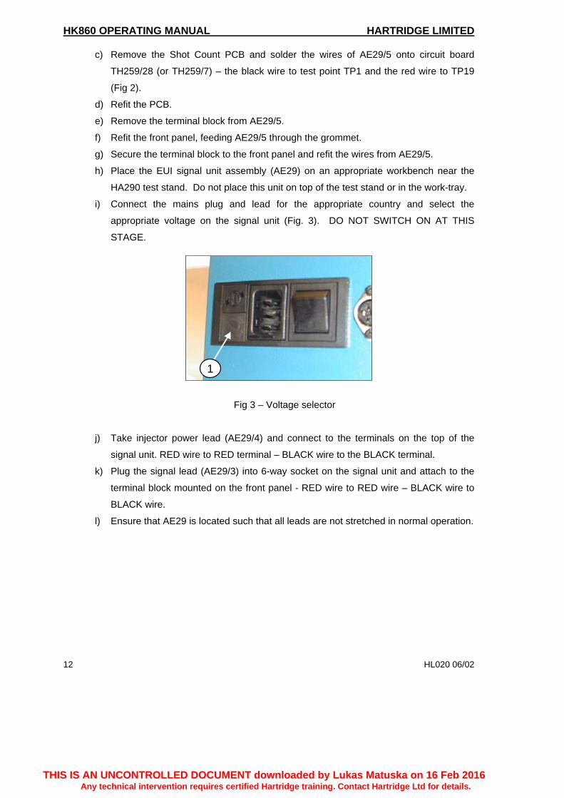
i) Connect the mains plug and lead for the appropriate country and select the
appropriate voltage on the signal unit (Fig. 3). DO NOT SWITCH ON AT THIS
STAGE.
Fig 3 – Voltage selector
j) Take injector power lead (AE29/4) and connect to the terminals on the top of the
signal unit. RED wire to RED terminal – BLACK wire to the BLACK terminal.
k) Plug the signal lead (AE29/3) into 6-way socket on the signal unit and attach to the
terminal block mounted on the front panel - RED wire to RED wire – BLACK wire to
BLACK wire.
l) Ensure that AE29 is located such that all leads are not stretched in normal operation.
1
THIS IS AN UNCONTROLLED DOCUMENT downloaded by Lukas Matuska on 16 Feb 2016Any technical intervention requires certified Hartridge training. Contact Hartridge Ltd for details.
HARTRIDGE LIMITED HK860 OPERATING MANUAL
HL020 06/02 13
3.2. MECHANICAL
Isolate the electrical supply before carrying out any test stand modifications.
a) Install 0.426” CAM (Hartridge part no. YDB438) in the test stand cambox.
b) Remove existing injector support (TH229/2) from the main bracket and replace with
the new two part injector support assembly, TH380.
Note: The injector support is an interference fit into the main bracket. Ensure the
Vee bracket is aligned correctly before fitting.
3.2.1 Fuel Arm Modification a) Disconnect the fuel supply pipe from the banjo on the fuel arm and fit the male quick
release connector, ALP320, directly into the banjo fitting (using an appropriate thread
sealant).
b) Fit the female quick release connector, 8924201, to the fuel supply pipe.
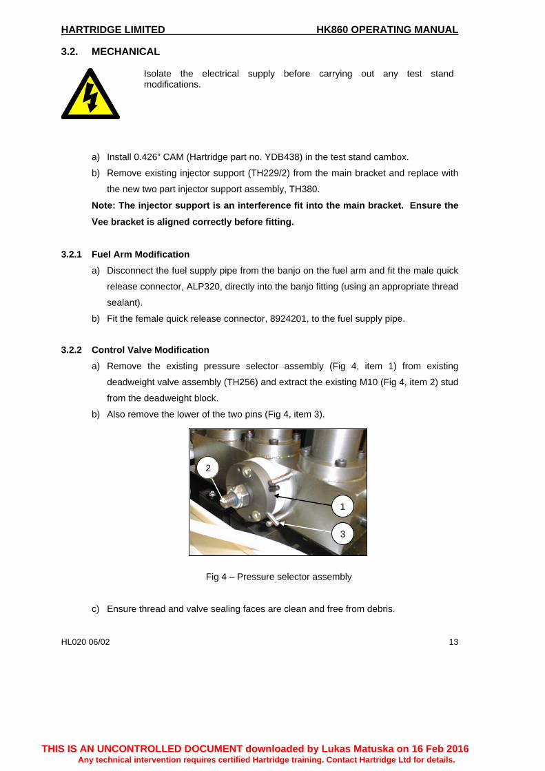
3.2.2 Control Valve Modification a) Remove the existing pressure selector assembly (Fig 4, item 1) from existing
deadweight valve assembly (TH256) and extract the existing M10 (Fig 4, item 2) stud
from the deadweight block.
b) Also remove the lower of the two pins (Fig 4, item 3).
Fig 4 – Pressure selector assembly
c) Ensure thread and valve sealing faces are clean and free from debris.
1
2
3
THIS IS AN UNCONTROLLED DOCUMENT downloaded by Lukas Matuska on 16 Feb 2016Any technical intervention requires certified Hartridge training. Contact Hartridge Ltd for details.

HK860 OPERATING MANUAL HARTRIDGE LIMITED
14 HL020 06/02
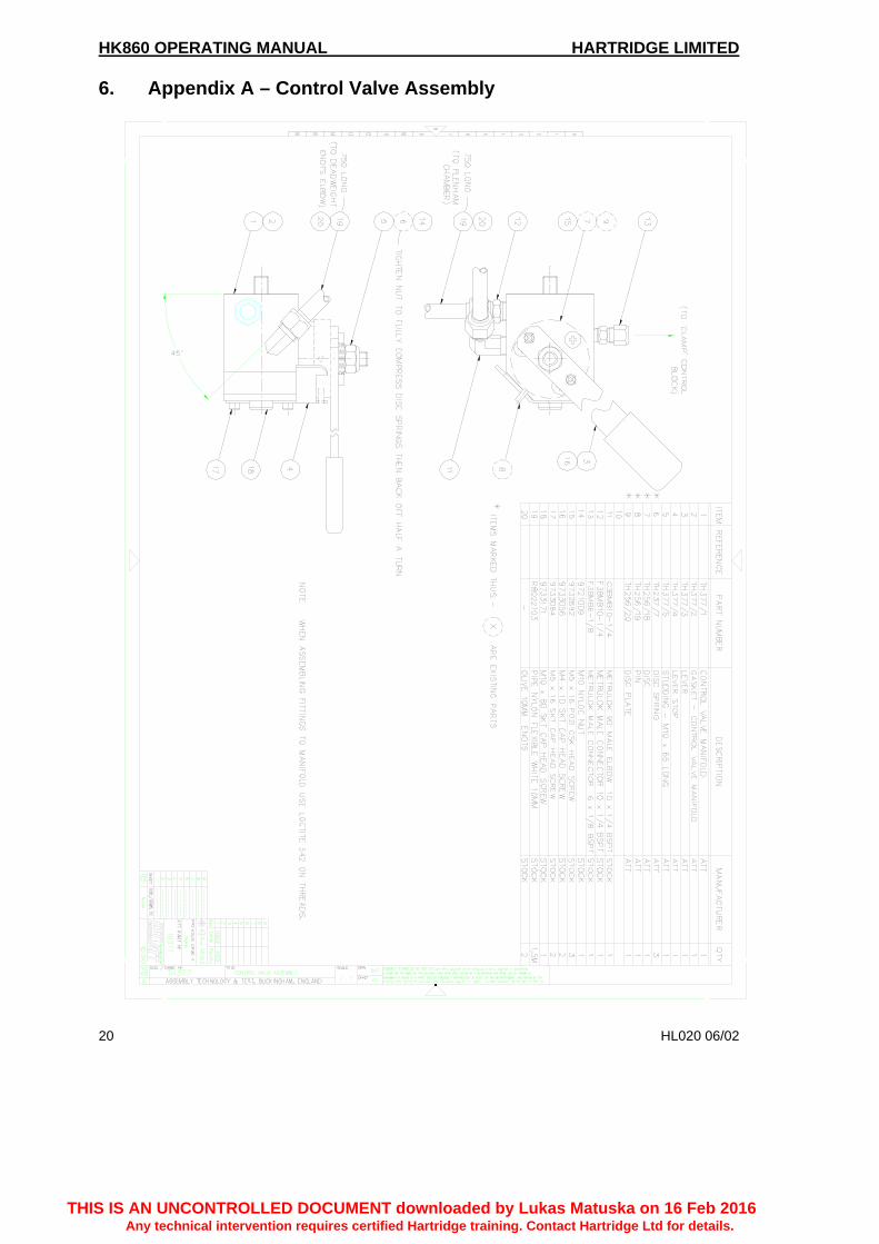
d) Use the following existing parts from the old control valve to build the new control
valve assembly, with reference to drawing TH377 (Appendix A):-
- DISC SPRING TH237/7
- DISC TH256/18
- PIN TH256/19
- DISC PLATE TH256/20
Note: it is recommended that the new pipes are fitted to the assembly prior to
fitment to the bench.
e) Fit the new assembly using the M10 bolt provided. Ensure block is square and that
gasket is correctly fitted. Tighten bolt down hard (35 lbs ft – 25 NM approx.)
Note: To fit the new manifold assembly it will be necessary to make a minor
modification to the front panel for clearance.
f) Re-pipe new control valve block into circuit as follows (ref: drawing TH377, Appendix
A):-
- M6 nylon pipe (block to injector clamp control block)
- M10 nylon pipe (block to plenham chamber)
- M10 nylon pipe (block to deadweight ENOTS elbow)
3.2.3 Deadweight Modification
Fig 5 – Original deadweight assembly Fig 6 – Modified deadweight assembly
a) Remove existing 12 psi deadweight from the deadweight valve assembly (the right
hand of the three locations) and discard (refer to Fig 5).
b) Move the 74 psi deadweight to the right hand deadweight location (refer to Fig 6).
c) Move the 100 psi deadweight to the middle deadweight location.
100psi
120psi
74psi
74psi
12psi
100psi
THIS IS AN UNCONTROLLED DOCUMENT downloaded by Lukas Matuska on 16 Feb 2016Any technical intervention requires certified Hartridge training. Contact Hartridge Ltd for details.

HARTRIDGE LIMITED HK860 OPERATING MANUAL
HL020 06/02 15
d) Install the new 120 psi deadweight (TH379) to the left hand deadweight location.
e) Ensure the selector lever is turned hard to the right.
f) START Fuel system (check for leaks), run the system until the temperature comes
into range and then re-check for leaks.
3.2.4 Nose Cone Assembly Modification
NOTE: Ensure a suitable audit kit is used during the setup of the machine (e.g.
HB164).
a) Remove the existing nose cone assembly (TH265) and replace the nose cone seal
(Fig 7, item 2) and seal retainer (Fig 7, item 1), ref: drawing no. TH378 (Appendix
B).
Note: The replacement seal is an interference fit and care needs to be taken when
pressing it into position.
Fig 7 – Nose cone assembly
b) Recheck the sealing pressure and check the valve assemble for leaks using the
procedure outlined in the HA290 operating and service manual, section 2.5.4.
c) With system up to temperature, check the clamp pressures (120 and 74 psi) are
correct by adjusting the appropriate deadweight. Use the procedure outlined in
section 2.5.3. of the HA290 operating and service manual, using the lever on the
pressure selector assembly to select the appropriate clamp pressure.
NOTE: Lever fully anti-clockwise = 120psi selected.
Lever fully clockwise = 100psi selected.
d) Check the operating pressure (100psi) using the procedure outlined in section 2.5.2.
of the HA290 operating and service manual.
2
1
THIS IS AN UNCONTROLLED DOCUMENT downloaded by Lukas Matuska on 16 Feb 2016Any technical intervention requires certified Hartridge training. Contact Hartridge Ltd for details.

HK860 OPERATING MANUAL HARTRIDGE LIMITED
16 HL020 06/02
3.2.5 Injector Guard Modification In order to accommodate the EUI solenoid, it is necessary to remove the guard and
modify as per drawing TH382 (Appendix C)
THIS IS AN UNCONTROLLED DOCUMENT downloaded by Lukas Matuska on 16 Feb 2016Any technical intervention requires certified Hartridge training. Contact Hartridge Ltd for details.

HARTRIDGE LIMITED HK860 OPERATING MANUAL
HL020 06/02 17
4. OPERATION 4.1. OPERATING PRINCIPLES
The CUMMINS EUI injector is based on the proven CUMMINS PT system, but with an electronically controlled solenoid valve delivering fluid into the metered chamber rather than the metered volume being governed by the supply pressure and fuel flow across a fixed inlet orifice. The injector nose assembly, like the PT system, has injection and spill galleries separated by ‘o’-rings. Once injection has ceased the test fluid is by-passed to tank cooling the injector through the spill gallery. The metering pulse and the injection pulse need to be phased relative to the cam lift and crank position in order to deliver the right quantity of fluid into the cylinder head at the correct time. In order to perform this function on the HA290 test stand a variable potentiometer control is provided in the signal unit assembly test box. This control allows an optimum time delay (angle) to be set between the start of metering and a reference timing signal related to the HA290 camshaft lift. The duration of the injection pulse, and therefore fuel delivery, can be adjusted in discrete steps using a rotary switch on the HK860 signal box (refer to Appendix D).
4.2. OPERATING PROCEDURE
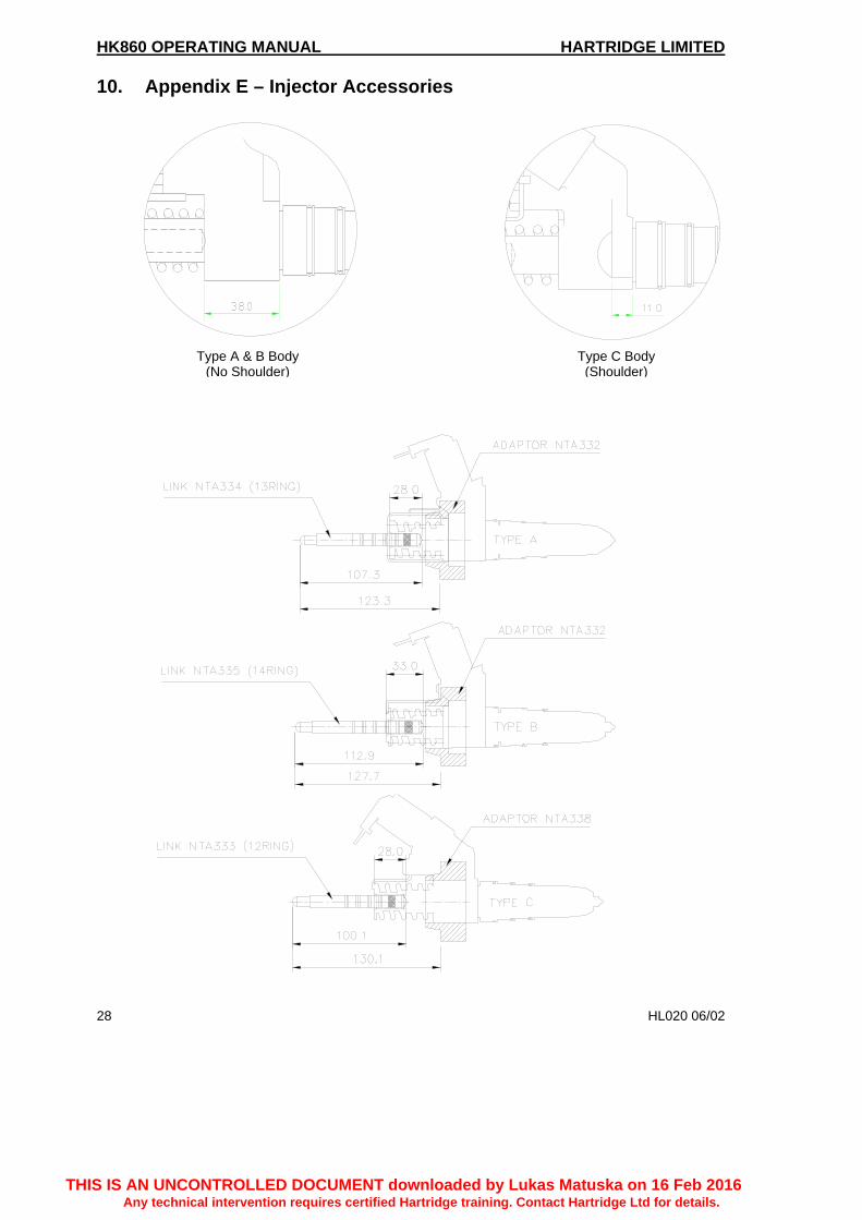
a) Using a reference injector, select the appropriate link and adaptor combination
(Appendix E).
b) Fit the fuelling sleeve over the injector, taking care to ensure it is fully located.
c) Remove the Vee bracket from the injector support leaving a plain bar end.
d) Load the injector, link and adaptor into the test stand’s fixturing, ensuring the groove
in the sleeve locates over the injector support bar.
e) Clamp the injector.
f) Connect up the EUI signal unit assembly (AE29).
g) Connect the power to the unit.
h) Connect the injector power lead as per drawing AE29/3.
i) Select the minimum time delay using the injection delay potentiometer.
j) Select the minimum pulse width using the pulse width selector switch.
k) Ensure that the fuel supply is on and check that fuel is spilled from the hole at the
bottom of the fuel sleeve.
l) Ensure no fuel is leaking from either end of the sleeve (which would indicate either
incorrect fitment of the sleeve or damaged seals).
m) Start the test bench running with no signal applied from the signal unit.
n) Turn on the signal unit and adjust injection delay potentiometer until maximum fuel is
achieved.
THIS IS AN UNCONTROLLED DOCUMENT downloaded by Lukas Matuska on 16 Feb 2016Any technical intervention requires certified Hartridge training. Contact Hartridge Ltd for details.

HK860 OPERATING MANUAL HARTRIDGE LIMITED
18 HL020 06/02
o) Lock off the delay potentiometer. The unit is now set and ready to test the same type of EUI as that used as the reference injector.
p) Fit the injector to be tested as described in sections (a) to (g) but DO NOT reset the delay potentiometer.
NOTE: Adjusting the delay potentiometer will alter the spill timing in relation to the HA290 cam lift. This will affect the fuelling achieved (see Fig 8). q) Follows sections (j) to (l).
r) The injector is now ready to be tested at various pulse widths and the results compared to the performance of the reference injector to confirm that the injector performance is as required.
Fig 8 – Example of the effect of injection delay on delivery
5. MAINTENANCE Carry out the routine maintenance as defined in the Hartridge HA290 operating and service manual.
EUI Delivery vs Injection Delay
0
50
100
150
200
250
300
350
0 5 10 15 20 25 30
Injection delay (ms)
Del
iver
y (m
m3/
stk)
25 ms PW20 ms PW17.5 ms PW15 ms PW
THIS IS AN UNCONTROLLED DOCUMENT downloaded by Lukas Matuska on 16 Feb 2016Any technical intervention requires certified Hartridge training. Contact Hartridge Ltd for details.

HARTRIDGE LIMITED HK860 OPERATING MANUAL
HL020 06/02 19
This page is deliberately left blank
THIS IS AN UNCONTROLLED DOCUMENT downloaded by Lukas Matuska on 16 Feb 2016Any technical intervention requires certified Hartridge training. Contact Hartridge Ltd for details.
HK860 OPERATING MANUAL HARTRIDGE LIMITED
20 HL020 06/02
6. Appendix A – Control Valve Assembly
THIS IS AN UNCONTROLLED DOCUMENT downloaded by Lukas Matuska on 16 Feb 2016Any technical intervention requires certified Hartridge training. Contact Hartridge Ltd for details.

HARTRIDGE LIMITED HK860 OPERATING MANUAL
HL020 06/02 21
This page is deliberately left blank
THIS IS AN UNCONTROLLED DOCUMENT downloaded by Lukas Matuska on 16 Feb 2016Any technical intervention requires certified Hartridge training. Contact Hartridge Ltd for details.

HK860 OPERATING MANUAL HARTRIDGE LIMITED
22 HL020 06/02
7. Appendix B – Nose Cone Assembly
THIS IS AN UNCONTROLLED DOCUMENT downloaded by Lukas Matuska on 16 Feb 2016Any technical intervention requires certified Hartridge training. Contact Hartridge Ltd for details.

HARTRIDGE LIMITED HK860 OPERATING MANUAL
HL020 06/02 23
This page is deliberately left blank
THIS IS AN UNCONTROLLED DOCUMENT downloaded by Lukas Matuska on 16 Feb 2016Any technical intervention requires certified Hartridge training. Contact Hartridge Ltd for details.

HK860 OPERATING MANUAL HARTRIDGE LIMITED
24 HL020 06/02
8. Appendix C – Guard Modification
THIS IS AN UNCONTROLLED DOCUMENT downloaded by Lukas Matuska on 16 Feb 2016Any technical intervention requires certified Hartridge training. Contact Hartridge Ltd for details.

HARTRIDGE LIMITED HK860 OPERATING MANUAL
HL020 06/02 25
This page is deliberately left blank
THIS IS AN UNCONTROLLED DOCUMENT downloaded by Lukas Matuska on 16 Feb 2016Any technical intervention requires certified Hartridge training. Contact Hartridge Ltd for details.

HK860 OPERATING MANUAL HARTRIDGE LIMITED
26 HL020 06/02
9. Appendix D – Timing diagram
THIS IS AN UNCONTROLLED DOCUMENT downloaded by Lukas Matuska on 16 Feb 2016Any technical intervention requires certified Hartridge training. Contact Hartridge Ltd for details.

HARTRIDGE LIMITED HK860 OPERATING MANUAL
HL020 06/02 27
This page is deliberately left blank
THIS IS AN UNCONTROLLED DOCUMENT downloaded by Lukas Matuska on 16 Feb 2016Any technical intervention requires certified Hartridge training. Contact Hartridge Ltd for details.
HK860 OPERATING MANUAL HARTRIDGE LIMITED
28 HL020 06/02
10. Appendix E – Injector Accessories Type A & B Body Type C Body (No Shoulder) (Shoulder)
THIS IS AN UNCONTROLLED DOCUMENT downloaded by Lukas Matuska on 16 Feb 2016Any technical intervention requires certified Hartridge training. Contact Hartridge Ltd for details.