hiwin linear guideways - ruch servomotorruchservomotor.com/pdf_english/h_l_g_(low).pdf ·...
TRANSCRIPT

Ruchservomotor JV 220141, Kooprevicha Str. 1/3, Minsk, Republic of Belarus. http://www.ruchservomotor.com
HIWIN LINEAR GUIDEWAY
Technical Information Index
Preface......................................................................................................................... 3
1. General Information.......................................................................................... 3
1-1 Advantages and Features of Linear Guideway...................................... 3
1-2 The Principles of Selecting Linear Guideway........................................ 6
1-3 Basic Load Rating of Linear Guideway................................................... 7
1-4 The Service Life of Linear Guideway........................................................ 7
1-5 Acting Load..................................................................................................... 10
1-6 Friction............................................................................................................. 12
1-7 Lubrication...................................................................................................... 13
1-8 The Butt-joint Rail.......................................................................................... 13
1-9 Layout Method................................................................................................ 14
1-10 Installation of Linear Guideway............................................................... 15
2. HIWIN Linear Guideway Product Series.................................................. 19
2-1 LG Series.................................................................................................... 20
2-1-1 Features of the LG Series Linear Guideway.......................................... 20
2-1-2 Construction of LG Series....................................................................... 20
2-1-3 Model Number of LG Series..................................................................... 20
2-1-4 Types.......................................................................................................... 22
2-1-5 Accuracy Classes..................................................................................... 23
2-1-6 Preload....................................................................................................... 26
2-1-7 Stiffness..................................................................................................... 27
2-1-8 Lubrication................................................................................................ 27
2-1-9 Dust Protection Equipment...................................................................... 29
2-1-10 Friction..................................................................................................... 30
2-1-11 The Accuracy Tolerance of Mounting Surface..................................... 31
2-1-12 Cautions for Installation......................................................................... 32
2-1-13 Standard Length and Max. Length of Rail............................................ 33
2-1-14 Dimensions for HIWIN LG Series.......................................................... 35
2-2 AG Series........................................................................................................ 40
2-2-1 Features of the AG Series Linear Guideway.......................................... 40
2-2-2 Construction of AG Series....................................................................... 40
2-2-3 Model Number of AG Series.................................................................... 40
2-2-4 Types......................................................................................................... 42
2-2-5 Accuracy Classes..................................................................................... 43

Ruchservomotor JV 220141, Kooprevicha Str. 1/3, Minsk, Republic of Belarus. http://www.ruchservomotor.com
2-2-6 Preload....................................................................................................... 45
2-2-7 Stiffness..................................................................................................... 45
2-2-8 Lubrication................................................................................................. 45
2-2-9 Dust Protection Equipment...................................................................... 47
2-2-10 Friction..................................................................................................... 48
2-2-11 The Accuracy Tolerance of Mounting Surface..................................... 48
2-2-12 Cautions for Installation......................................................................... 50
2-2-13 Standard Length and Max. Length of Rail............................................ 51
2-2-14 Dimensions for HIWIN AG Series.......................................................... 52
2-3 Miniature MGN / MGW Series..................................................................... 56
2-3-1 Features of MGN Series........................................................................... 56
2-3-2 Construction of MGN Series.................................................................... 56
2-3-3 Features of MGW Series........................................................................... 56
2-3-4 Construction of MGW Series................................................................... 57
2-3-5 Application................................................................................................. 57
2-3-6 Model Number of MGN / MGW Series..................................................... 57
2-3-7 Accuracy Classes..................................................................................... 59
2-3-8 Preload....................................................................................................... 60
2-3-9 Dust Protection Equipment...................................................................... 60
2-3-10 Shoulder Heights and Fillets................................................................. 61
2-3-11 Standard Length and Max. Length of Rail............................................ 61
2-3-12 Dimensions for HIWIN MGN / MGW Series........................................... 63
2-4 E1 (Self-Lubricated) Option Function....................................................... 65
2-5 Q1 (Low Noise) Option Function............................................................... 67
2-6 SE (Heat resistant) Option Function......................................................... 68
* The specifications in this catalogue are subject to change without notice.
Ruchservomotor JV 220141, Kooprevicha Str. 1/3, Minsk, Republic of Belarus. http://www.ruchservomotor.com
Preface
A linear guideway allows a type of linear motion that utilises rolling balls. By using circulating balls between the rail
and the block, a linear guideway can achieve high precision linear motion. Compared to a traditional slide, the coefficient
of friction for a linear guideway is only 1/50th. Because of the restraint effect between the rails and the blocks, linear
guideways can take up loads in both the up/down and the left/right directions. With these features, linear guideways can
greatly enhance moving accuracy, it is especially true when accompanied with precision ballscrews.
1 General Information
1-1 Advantages and Features of Linear Guideway
1-1-1 Advantages of Linear Guideways
(1) High positional accuracyWhen a loaded plate is driven by a linear motion guideway, the frictional contact between the loaded plate
and the bed is rolling contact. The coefficient of friction is only l/50th of traditional contact, and the difference
between the dynamic and the static coefficient of friction is small. Therefore, there would be no slippage while
the table is moving.
(2) Long life with highly accurate motionWith a traditional slide, errors in accuracy are caused by the counter flow of the oil film. Insufficient
lubrication causes wear between the contact surfaces, which become increasingly inaccurate. In contrast,
rolling contact has little wear; therefore, machine can achieve a long life with highly accurate motion.
(3) High speed motion is possible with a low driving forceBecause the linear guideway has little friction resistance, only a small driving force is needed for moving
the loaded table. The result of this fact is the power savings. This is especially true for the reciprocating parts.
(4) Equal loading capacity in all directionsBecause of its special constraint design, a linear guideway can take up loads in either the up/down or
left/right directions. Conventional linear slides can only take up small loads in the direction parallel to the
contact surface. They are also more likely to become inaccurate when they are subjected to these loads.
(5) Easy installation and interchangeabilityInstalling a linear guideway is fairly easy. Grinding or milling the machine surface, following a
recommended installation procedure, and tightening the bolts to their specified torque can achieve high
accuracy linear motion. However, a traditional slide takes more time to scrape the tracks. If any errors in
accuracy arise, the surface must be scraped again. In contrast, linear guideways are interchangeable.
(6) Easy lubricationWith a traditional sliding system, insufficient lubrication wears out the contact surfaces. Also, it can be
quite difficult to supply sufficient lubrication to the contact surfaces because finding an appropriate lubrication
point is not very easy. With a linear motion guideway, grease can be easily supplied through the grease nipple
on the linear guideway block. It is also possible to utilise a centralised oil lubrication system by piping the
lubrication oil to piping joint.
Ruchservomotor JV 220141, Kooprevicha Str. 1/3, Minsk, Republic of Belarus. http://www.ruchservomotor.com
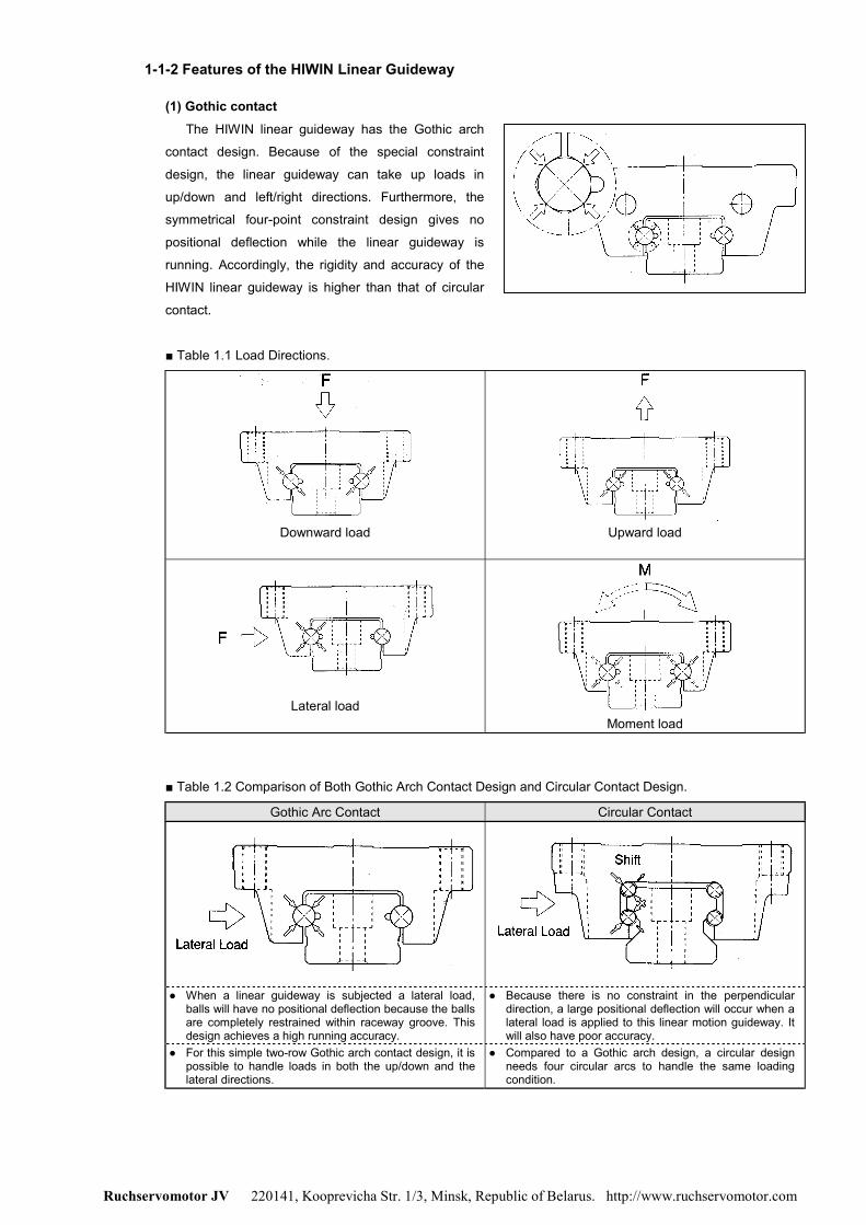
1-1-2 Features of the HIWIN Linear Guideway
(1) Gothic contactThe HIWIN linear guideway has the Gothic arch
contact design. Because of the special constraint
design, the linear guideway can take up loads in
up/down and left/right directions. Furthermore, the
symmetrical four-point constraint design gives no
positional deflection while the linear guideway is
running. Accordingly, the rigidity and accuracy of the
HIWIN linear guideway is higher than that of circular
contact.
■ Table 1.1 Load Directions.
Downward load Upward load
Lateral loadMoment load
■ Table 1.2 Comparison of Both Gothic Arch Contact Design and Circular Contact Design.
Gothic Arc Contact Circular Contact
● When a linear guideway is subjected a lateral load,balls will have no positional deflection because the ballsare completely restrained within raceway groove. Thisdesign achieves a high running accuracy.
● Because there is no constraint in the perpendiculardirection, a large positional deflection will occur when alateral load is applied to this linear motion guideway. Itwill also have poor accuracy.
● For this simple two-row Gothic arch contact design, it ispossible to handle loads in both the up/down and thelateral directions.
● Compared to a Gothic arch design, a circular designneeds four circular arcs to handle the same loadingcondition.

Ruchservomotor JV 220141, Kooprevicha Str. 1/3, Minsk, Republic of Belarus. http://www.ruchservomotor.com
(2) InterchangeabilityBecause of restricted dimension control, the dimensional difference of linear guideways can be kept in a
reasonable range, and which means that the specific series of linear guideways possess the
interchangeability. For this characteristic, it is good to have the stock of rails and blocks separately for saving
the space of warehouse.
(3) The optimum designAs for the design of circulating system, HIWIN has obtained patents from many developed countries.
Enlarged ball diameter and circulating curve ratio of design makes circulation smoother as well as makes
service life longer.
(4) High accuracyAs shown in the figure, both sides of raceway groove are ground simultaneously, and this ensures nearly
perfect parallelism for all four surfaces. Therefore, high accuracy repetition is possible when it is installed by
tightening the mounting bolts with torque wrench to a specified torque.

Ruchservomotor JV 220141, Kooprevicha Str. 1/3, Minsk, Republic of Belarus. http://www.ruchservomotor.com
1-2 The Principles of Selecting Linear Guideway
Identify the condition
• Applied equipment• Inner space limit• Accuracy• Stiffness• Way of loading
• Moving distance• Moving speed, acceleration• Using frequency• Using life• Environment
Selection of series
• LG series – Grinding, milling and drilling machine, lathe, machine centre• AG series – Automatic equipment, high speed transfer device, semiconductor equipment,
wood cutting machine, precision measure equipment• MGN/MGW series – Miniature device, semiconductor equipment, medical equipment
Selection of accuracy
• Classes: C, H, P, SP, UP depends on the accuracy of equipment
Assuming the size & the number of blocks
• Depends on experiences• Load condition• If accompanied with a ballscrew, the size should be similar to the diameter of ballscrew.
For example, if the outer diameter of the ballscrew is 35mm, then the model size of linearguideway should be LG35
Calculate the max. load of block
• Make reference to load calculation examples, and calculate the max. load• Be sure that the static safety factor of selected guideway is bigger than that in the table of
static safety factor
Choosing preload
• Depends on the stiffness requirement and accuracy of mounting surface
Identify stiffness
• Calculate the deformation (δ) by using the table of stiffness values, choosing heavierpreload and bigger size linear guideway to enhance the stiffness
Calculating service life
• Calculate the life time requirement by using the moving speed and frequency. Makereference to the life calculation example
Selection of lubrication
• Grease supplied by grease nipple• Oil supplied by piping joint
Complete of selection

Ruchservomotor JV 220141, Kooprevicha Str. 1/3, Minsk, Republic of Belarus. http://www.ruchservomotor.com
1-3 Basic Load Rating of Linear Guideway
1-3-1 Basic Static Load Rating (C0)(1) Definition
A local permanent deformation will be caused between the raceway surface and the rolling balls when a
linear guideway is subjected to an excessively large load or an impact load while either at rest or in motion. If
the amount of this permanent deformation exceeds a certain limit, it becomes an obstacle to the smooth
operation of the linear guideway. Generally, the definition of the basic static load rating is a static load of
constant magnitude and direction, which results in a total permanent deformation of 0.0001 times the diameter
of the rolling ball for the rolling ball and the raceway at the contact point subjected to the largest stress. The
value is described in the dimension tables for each linear guideway. A designer can select a suitable linear
guideway by referring to these tables. The maximum static load applied to a linear guideway must not exceed
the basic static load rating.
(2) Static safety factorAppropriate safety factors, which depend on environmental and operating conditions, must be taken into
consideration. A larger safety factor is especially important for guideways subject to impact loads (See
Table 1.3). The static load can be obtained by using Eq. 1.1.
■ Table 1.3 Static safety factor.
Load Condition ƒƒƒƒs
Normal load 1.0 ~ 3.0With impacts/vibrations 3.0 ~ 5.0
PC0
s =ƒ ………………………………Eq. 1.1
C0 : Basic static load rating (kgf) ƒƒƒƒs : Static safety factor
P : Working load (kgf)
1-3-2 Basic Dynamic Load Rating (C)The basic dynamic load rating is the load that does not change in direction or magnitude and results in a
nominal life of 50km of operation for a linear guideway. The values for the basic dynamic load rating of each
guideway are shown in dimension tables. They can be used to predict the service life for a selected linear
guideway.
1-4 The Service Life of Linear Guideway
1-4-1 Service Life (С)When the raceway and the rolling balls of a linear guideway are continuously subjected to repeated stresses,
the raceway surface shows fatigue. Flaking will eventually occur. This is called fatigue flaking. The life of a linear
guideway is defined as the total distance travelled until the fatigue flaking appears at the surface of raceway or
rolling balls.
1-4-2 Nominal Life (L)The service life varies widely even when the linear motion guideways are manufactured in the same way or
operated under the same motion conditions. For this reason, nominal life is used as the criteria for predicting the
service life of a linear motion guideway. The nominal life is the total distance that 90% of a group of identical
linear motion guideways, operated under identical conditions, can travel without flaking. When the basic dynamic
rated load is applied to a linear motion guideway, the nominal life is 50km.

Ruchservomotor JV 220141, Kooprevicha Str. 1/3, Minsk, Republic of Belarus. http://www.ruchservomotor.com
1-4-3 Calculation of Nominal LifeThe acting load will affect the nominal life of a linear guideway. Based on the selected basic dynamic rated
load and the actual load, the nominal life can be calculated by using Eq. 1.2.
50kmPCL
3
×
= ………………….........Eq. 1.2
L : Nominal life (km) P : Actual load (kgf) C : Basic dynamic load rating (kgf)
If the environmental factors are taken into consideration, the nominal life is influenced widely by the motion
conditions, the hardness of the raceway, and the temperature of the linear guideway. The relationship between
these factors is expressed in Eq. 1.3.
50kmPCL
3
cw
th ×
׃
׃׃= ……….........Eq. 1.3
L : Nominal life (km) C : Basic dynamic load rating (kgf) Pc : Calculated load (kgf)
ƒƒƒƒh : Hardness factor ƒƒƒƒt : Temperature factor ƒƒƒƒw : Load factor
1-4-4 Factors of Nominal Life
(1) Hardness factor (ƒƒƒƒh)In general, the raceway surface in contact with the balls must have the hardness of HRC 58~64 to an
appropriate depth. When the specified hardness is not obtained, the permissible load is reduced and the
nominal life is decreased. In this situation, the basic dynamic load rating and the basic static load rating must
be multiplied by the hardness factor for calculation.
■ Raceway hardness:
(2) Temperature factor (ƒƒƒƒt)When the temperature of a linear guideway exceeds 100°C the permissible load is reduced and the
nominal life is decreased. Therefore, the basic dynamic load rating and the basic static load rating must be
multiplied by the temperature factor.
■ Temperature:
(3) Load factor (ƒƒƒƒw)The loads acting on a linear guideway include the weight of slide, the inertia load at the times of start and
stop, and the moment loads caused by overhanging. These load factors are especially difficult to estimate
because of mechanical vibrations and impacts. Therefore, the load on linear guideway should be divided by
the empirical factor.
■ Table 1.4 Load factor:
Loading condition Service speed ƒw
No impacts & vibration Low speed V ≤ 15 m/min 1 ~ 1.5Normal load Medium speed 15 < V ≤ 60 m/min 1.5 ~ 2.0
With impacts & vibration High speed V > 60 m/min 2.0 ~ 3.5

Ruchservomotor JV 220141, Kooprevicha Str. 1/3, Minsk, Republic of Belarus. http://www.ruchservomotor.com
(4) Calculation of the service life time (Lh)Transform the nominal life into life time by using the speed and frequency.
hr60S
1050PC
60S10L
33
3
×
××
=××=hL …………Eq. 1.4
Lh : Service life time (hr) S : Speed (m/min)
L : Nominal life (km) C/P : Load ratio
If the load ratio and speed have been calculated, the service life time can be obtained easily from the
service life nomogram.
■ Table 1.5 Service life time nomogram:
A surface grinding machine has a working load 2000kgf (500kgf per block) and 10m/min feed rate. What is theservice life time when the machine uses a set of HIWIN LGW35CA linear guideways?
►By checking the dimension table, the basic dynamic load rating of LGW35CA is 4180kgf, so the load ratio is:
36.8500180,4
PC ==
► Calculate the nominal life: ( ) km214,295036.850PCL 3
3
=×=×
=
► According to the intersection of the line of load ratio and the line of speed, the service life time is 49000hr► Lh can also be obtained by substituting the numerical values into Eq. 1.4:
( ) hr690,486010
105036.860S
1050PC
L33
33
h =×
××=×
××
=
► Assume the frequency is 50% and its service life is 11 years.

Ruchservomotor JV 220141, Kooprevicha Str. 1/3, Minsk, Republic of Belarus. http://www.ruchservomotor.com
1-5 Acting Load
1-5-1 Calculation of LoadSeveral factors affect the calculation of the loads acting on a linear guideway (such as the position of the
centre gravity of object, the thrust position, and the inertial forces at the times of start and stop). To obtain the
correct load value, each loading condition should be carefully taken into consideration.
(1) Load on one block
■ Table 1.6 Calculation Examples.
Patterns Load layout Load on one block
d2bF
c2aF
4F
4WP1
×+×++=
d2bF
c2aF
4F
4WP2
×−×++=
d2bF
c2aF
4F
4WP3
×+×−+=
d2bF
c2aF
4F
4WP4
×−×−+=
d2bF
c2aF
4F
4WP1
×+×++=
d2bF
c2aF
4F
4WP2
×−×++=
d2bF
c2aF
4F
4WP3
×+×−+=
d2bF
c2aF
4F
4WP4
×−×−+=
d2lF
4WPP 31
×−==
d2lF
4WPP 42
×+==
d2lF
d2hWP~P 41
×+×−=
c2lF
c2hWP~P 41
×+×−=
d2kF
4F
4WPP 3t1t
×++==
d2kF
4F
4WPP 4t2t
×−+==
Ruchservomotor JV 220141, Kooprevicha Str. 1/3, Minsk, Republic of Belarus. http://www.ruchservomotor.com
(2) Loads with inertia forces
■ Table 1.7 Calculation examples for loads with inertia forces
Considering the acceleration and deceleration Load on one block► Constant velocity:
4WP~P 41 =
► Acceleration:
dl
tV
gW
21
4WPP
1
c31 ×××+==
dl
tV
gW
21
4WPP
1
c42 ×××−==
► Deceleration:
dl
tV
gW
21
4WPP
3
c31 ×××−==
dl
tV
gW
21
4WPP
3
c42 ×××+==
1-5-2 Calculation of the Mean Load for Fluctuating LoadsWhen the load on a linear guideway fluctuates greatly, the variable load condition must be considered in the
life calculation. The definition of the mean load is the load equal to the bearing fatigue load under the variable
loading conditions. It can be calculated by using table 1.8.
■ Table 1.8 Calculation examples for mean load (Pm)
Operation condition Mean loadVariation in steps
( )3n
3n2
321
31m LPLPLPL
1P ×++×+×= K
Pm: Mean load (kgf)Pn: Fluctuating load (kgf)L: Total running distance (m)Ln: Running distance under load Pn (m)
Simple fluctuating
( )maxminm P2P31P ×+=
Pm: Mean load (kgf)Pmin: Min. load (kgf)Pmax: Max. load (kgf)
Sin curve fluctuating
maxm P65.0P ×=
Pm: Mean fluctuating load (kgf)Pmax: Max. fluctuating load (kgf)
Ruchservomotor JV 220141, Kooprevicha Str. 1/3, Minsk, Republic of Belarus. http://www.ruchservomotor.com
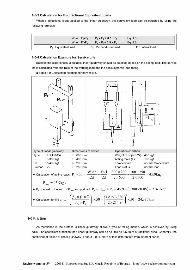
1-5-3 Calculation for Bi-directional Equivalent LoadsWhen bi-directional loads applied to the linear guideway, the equivalent load can be obtained by using the
following formulas
When Fs>Fl, Pe = Fs + 0.5 ×××× Fl …….Eq. 1.5When Fl>Fs, Pe = Fl + 0.5 ×××× Fs …….Eq. 1.6
Pe : Equivalent load Fs : Perpendicular load Fl : Lateral load
1-5-4 Calculation Example for Service LifeBesides the experiences, a suitable linear guideway should be selected based on the acting load. The service
life is calculated from the ratio of the working load and the basic dynamic load rating.
■ Table 1.9 Calculation example for service life.
Type of linear guideway Dimensions of device Operation conditionType : LGH30-CAC : 3,380 kgfC0 : 5,460 kgfPreload : Z2
d : 600 mmc : 400 mmh : 200 mml : 250 mm
Weight of object (W) : 400 kgfActing force (F) : 100 kgfTemperature : normal temperatureLoad status : normal load
► Calculation of acting loads: f41 kg9.456002250100
6002200300
d2lF
d2hWP~P =
××−
××=×−×=
fmax kg9.45P =
► Pc in equal to the sum of Pmax and preload: ( ) kgf9.21405.0380,39.45PPP zmaxc =×+=+=
► Calculation for life L: km317,24509.2142
380,31150P
CL
33
cw
th =×
×××=×
׃
׃׃=
1-6 Friction
As mentioned in the preface, a linear guideway allows a type of rolling motion, which is achieved by using
balls. The coefficient of friction for a linear guideway can be as little as 1/50th of a traditional slide. Generally, the
coefficient of friction of linear guideway is about 0.004, more or less differentiate from different series.

Ruchservomotor JV 220141, Kooprevicha Str. 1/3, Minsk, Republic of Belarus. http://www.ruchservomotor.com
When a load is 10% or less than the basic static load rate, the most of the resistance come from the grease
resistance and frictional resistance between balls. In contrast, if the load is more than the basic static load rate,
the resistance will be mainly comes form the load.
F = µµµµ ×××× W + f ……………………….Eq. 1.7F: Friction (kgf) µ: Coefficient of friction
f: Friction resistance (kgf) W: Loads (kgf)
1-7 Lubrication
1-7-1 GreaseEach linear guideway is lubricated with lithium soap base grease No. 2 before shipment. After the linear
guideway been installed, we recommended that the replenishment should be held every 100 km. It is possible to
carry out the lubrication by piping the grease nipple. Generally, the grease is suitable for the running speed not
over 60 m/min or the cooling function is not important.
hr60S1000100T
××= ……………………Eq. 1.8
T: Feeding frequency of oil (hour) S: Speed (m/min)
1-7-2 OilThe recommended viscosity of oil is about 30 ~ 150 cst. The standard grease nipple may optionally be
replaced by oil piping joint for oil type lubrication. Since the oil is easier to evaporate than the grease, the
recommended oil feeding rate is about 0.3 cm3/hr.
1-8 The Butt-joint Rail
The butt-joint rail should be installed by following the arrow sign and ordinal number which is marked on the
surface of each rail. For paired butt-joint rails, the jointed position should be interlaced for avoiding the accuracy
problem due to the difference between different rails (see figure).

Ruchservomotor JV 220141, Kooprevicha Str. 1/3, Minsk, Republic of Belarus. http://www.ruchservomotor.com
1-9 Layout Method
The linear guideway can take up loads in up/down, left/right direction. The application depends on the
machine requirements and load directions. The typical layouts for linear guideway are shown below:
Use one rail and mounting reference side
Use of two rails (block movement) Use of two rails (block fixed)
Use of two external rails Use of two internal rails
Total surface fixed installationLGW type block with mounting holes in different
directions

Ruchservomotor JV 220141, Kooprevicha Str. 1/3, Minsk, Republic of Belarus. http://www.ruchservomotor.com
1-10 Installation of Linear Guideway
Three installation methods are recommended based on the required running accuracy and the degree of
impacts and vibrations.
■ Master and subsidiary guide:For non-interchangeable type Linear Guideway, there are some difference between the master guide and
subsidiary guide. The accuracy of master guide’s side datum plane is better than subsidiary’s and it can be a
reference side for installation. There is a mark “MA” printed on the rail, show as the figure.
1-10-1 Installation Example for Highly Required in Rigidity and Accuracy when Vibrations and Impacts
(1) Fixing methodsIt is possible that the rails and the blocks will be displaced when the machine is subjected to vibrations and
impacts. To eliminate these difficulties and achieve high running accuracy, the following four methods are
recommended for fixing.
Fixing with a push plateFixing with push screws
Fixing with taper gib Fixing with needle roller

Ruchservomotor JV 220141, Kooprevicha Str. 1/3, Minsk, Republic of Belarus. http://www.ruchservomotor.com
(2) Installation procedure of the rail
1. Before starting, remove all dirt from the
mounting surface of the machine.
2. Place the linear guideway gently on the bed.
Bring the guideway into close contact with the
datum plane of the bed.
3. Check for correct thread engagement when
inserting a bolt into the mounting hole while the
rail is being placed on the mounting surface of
the bed.
4. Tighten the push screws sequentially to ensure
close contact between the rail and the side
datum plane
5. Tighten the mounting bolts with a torque
wrench to the specified torque.
6. Install the remaining linear guideway in the
same way.
(3) Installation procedure of the block
1. Place the table gently on the blocks. Next,
tighten the block mounting bolts temporarily.
2. Push the blocks against the datum plane of the
table and position the table by tightening the
push screws.
3. The table can be fixed uniformly by tightening
the mounting bolts on master guide side and
subsidiary side in 1 to 4 sequences.

Ruchservomotor JV 220141, Kooprevicha Str. 1/3, Minsk, Republic of Belarus. http://www.ruchservomotor.com
1-10-2 Installation Example for the Case when a Rail on the Master Side Has no Push Screws
To ensure the parallelismbetween the subsidiary guideand the master guide withoutpush screws, the following railinstallation methods arerecommended. The blockinstallation is the same aswhich mentioned previously.
(1) Installation of the rail on the master guide side
► Using a vicePlace the rail into the mounting plane of the bed. Tightenthe mounting bolts temporarily; then use a vice to pushthe rail against the side datum plane of the bed. Tightenthe mounting bolts in sequence to the specified torque.
(2) Installation of the rail on the subsidiary guide side
► Method with use of a straight edgeSet a straight edge between the rails parallel to the side datumplane of the rail on the master guide side by using a dialgauge. Use the dial gauge to obtain the straight alignment ofthe rail on the subsidiary guide side. When the rail on thesubsidiary guide side is parallel to the master side, tighten themounting bolts in sequence from one end of the rail to theother.
► Method with use of a tableFix two blocks on the master guide side to the table.Temporarily fix the rail and one block on the subsidiary guideside to the bed and the table. Fixed a dial gauge stand on thetable surface and bring it into contact with the side of the blockon the subsidiary guide side. Move the table from one end ofthe rail to the other. While aligning the rail on the subsidiaryside parallel to the rail on the master guide side, tighten thebolts in sequence.
► Method following the master guide sideWhen a rail on the master guide side is correctly tightened, fixboth blocks on the master guide side and one of the two blockson the subsidiary guide side completely on the table. Whenmoving the table from one end of the rail, tighten the mountingbolts on the subsidiary guide side completely.
► Method with use of a jigUse a special jig to ensure the rail position on the subsidiaryguide side. Tighten the mounting bolts to the specified torquein sequence.

Ruchservomotor JV 220141, Kooprevicha Str. 1/3, Minsk, Republic of Belarus. http://www.ruchservomotor.com
1-10-3 Installation Example when there is no Side Surface of the Bed on the Master Guide Side
To ensure parallelism between the subsidiary guide and the master guide when there is no side surface, the
following rail installation method is recommended. The installation of the blocks is the same as which mentioned
previously.
(1) Installation of the rail on the master guide side
► Using a provisional datum plane
Two blocks are fixed in close contact by the measuring
plate. A datum plane provided on the bed is used for
straight alignment of the rail from one end to the other.
Move the blocks and tighten the mounting bolts to the
specified torque in sequence.
► Method with use of a straight edge
Use a dial gauge and a straight edge to confirm the
straightness of the side datum plane of the rail from one
end to the other. Make sure the mounting blots are
tightened securely in sequence
(2) Installation of the rail on the subsidiary guide side
The method of installation for the rail on the subsidiary guide side is the same as the case without push
screws.
Ruchservomotor JV 220141, Kooprevicha Str. 1/3, Minsk, Republic of Belarus. http://www.ruchservomotor.com
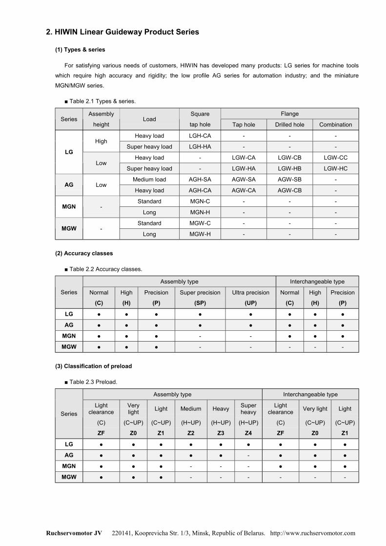
2. HIWIN Linear Guideway Product Series
(1) Types & series
For satisfying various needs of customers, HIWIN has developed many products: LG series for machine tools
which require high accuracy and rigidity; the low profile AG series for automation industry; and the miniature
MGN/MGW series.
■ Table 2.1 Types & series.
FlangeSeries
Assembly
heightLoad
Square
tap hole Tap hole Drilled hole Combination
Heavy load LGH-CA - - -High
Super heavy load LGH-HA - - -
Heavy load - LGW-CA LGW-CB LGW-CCLG
LowSuper heavy load - LGW-HA LGW-HB LGW-HC
Medium load AGH-SA AGW-SA AGW-SB -AG Low
Heavy load AGH-CA AGW-CA AGW-CB -
Standard MGN-C - - -MGN -
Long MGN-H - - -
Standard MGW-C - - -MGW -
Long MGW-H - - -
(2) Accuracy classes
■ Table 2.2 Accuracy classes.
Assembly type Interchangeable type
Series Normal
(C)
High
(H)
Precision
(P)
Super precision
(SP)
Ultra precision
(UP)
Normal
(C)
High
(H)
Precision
(P)
LG ● ● ● ● ● ● ● ●
AG ● ● ● ● ● ● ● ●
MGN ● ● ● - - ● ● ●
MGW ● ● ● - - - - -
(3) Classification of preload
■ Table 2.3 Preload.
Assembly type Interchangeable type
Lightclearance
Verylight Light Medium Heavy Super
heavyLight
clearance Very light LightSeries
(C)
ZF
(C~UP)
Z0
(C~UP)
Z1
(H~UP)
Z2
(H~UP)
Z3
(H~UP)
Z4
(C)
ZF
(C~UP)
Z0
(C~UP)
Z1
LG ● ● ● ● ● ● ● ● ●
AG ● ● ● ● ● - ● ● ●
MGN ● ● ● - - - ● ● ●
MGW ● ● ● - - - - - -

Ruchservomotor JV 220141, Kooprevicha Str. 1/3, Minsk, Republic of Belarus. http://www.ruchservomotor.com
2-1 LG Series
2-1-1 Features of the LG Series Linear GuidewayThe enlarged ball diameter design has increased the stiffness and the loading capacity, this makes the LG
series guideway especially suitable for the application with heavy working load. Moreover, the optimum design of
circulating system makes the movement smooth. The retainer is designed for avoiding the balls fall out even the
blocks are removed from the rail while installing.
2-1-2 Construction of LG Series
● Rolling circulating system: Block, rail, end plate and retainer.
● Lubrication system: Grease nipple and piping joint.
● Dust protection system: End seal, bottom seal, cap, double seals and scraper.
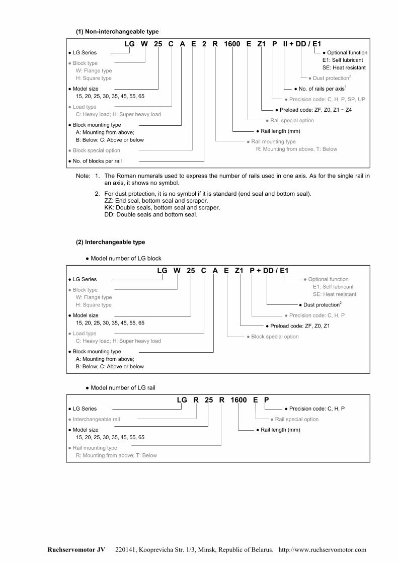
2-1-3 Model Number of LG SeriesLG series guideway can be classified into non-interchangeable and interchangeable types. The size of two
types is same as each other. The main difference between two types is that the interchangeable type of blocks
and rails can be freely exchanged, and their accuracy can reach up to P class. Because of the restrictedly
dimensional control, the interchangeable type linear guideway is a smart choice for customer when rails don't
need to be paired for an axis. The model number of LG series contains the size, type, accuracy class, preload
class, etc..
Ruchservomotor JV 220141, Kooprevicha Str. 1/3, Minsk, Republic of Belarus. http://www.ruchservomotor.com
(1) Non-interchangeable type
LG W 25 C A E 2 R 1600 E Z1 P II + DD / E1● LG Series
● Block typeW: Flange typeH: Square type
● Model size15, 20, 25, 30, 35, 45, 55, 65
● Load typeC: Heavy load; H: Super heavy load
● Block mounting typeA: Mounting from above;B: Below; C: Above or below
● Block special option
● No. of blocks per rail
● Optional functionE1: Self lubricantSE: Heat resistant
● Dust protection2
● No. of rails per axis1
● Precision code: C, H, P, SP, UP
● Preload code: ZF, Z0, Z1 ~ Z4
● Rail special option
● Rail length (mm)
● Rail mounting typeR: Mounting from above, T: Below
Note: 1. The Roman numerals used to express the number of rails used in one axis. As for the single rail inan axis, it shows no symbol.
2. For dust protection, it is no symbol if it is standard (end seal and bottom seal).ZZ: End seal, bottom seal and scraper.KK: Double seals, bottom seal and scraper.DD: Double seals and bottom seal.
(2) Interchangeable type
● Model number of LG block
LG W 25 C A E Z1 P + DD / E1● LG Series
● Block typeW: Flange typeH: Square type
● Model size15, 20, 25, 30, 35, 45, 55, 65
● Load typeC: Heavy load; H: Super heavy load
● Block mounting typeA: Mounting from above;B: Below; C: Above or below
● Optional functionE1: Self lubricantSE: Heat resistant
● Dust protection2
● Precision code: C, H, P
● Preload code: ZF, Z0, Z1
● Block special option
● Model number of LG rail
LG R 25 R 1600 E P● LG Series
● Interchangeable rail
● Model size15, 20, 25, 30, 35, 45, 55, 65
● Rail mounting typeR: Mounting from above; T: Below
● Precision code: C, H, P
● Rail special option
● Rail length (mm)
Ruchservomotor JV 220141, Kooprevicha Str. 1/3, Minsk, Republic of Belarus. http://www.ruchservomotor.com
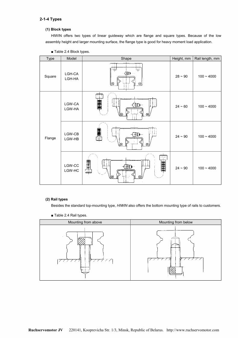
2-1-4 Types
(1) Block typesHIWIN offers two types of linear guideway which are flange and square types. Because of the low
assembly height and larger mounting surface, the flange type is good for heavy moment load application.
■ Table 2.4 Block types.
Type Model Shape Height, mm Rail length, mm
SquareLGH-CALGH-HA 28 ~ 90 100 ~ 4000
LGW-CALGW-HA
24 ~ 60 100 ~ 4000
LGW-CBLGW-HB
24 ~ 90 100 ~ 4000Flange
LGW-CCLGW-HC 24 ~ 90 100 ~ 4000
(2) Rail typesBesides the standard top-mounting type, HIWIN also offers the bottom mounting type of rails to customers.
■ Table 2.4 Rail types.
Mounting from above Mounting from below
Ruchservomotor JV 220141, Kooprevicha Str. 1/3, Minsk, Republic of Belarus. http://www.ruchservomotor.com
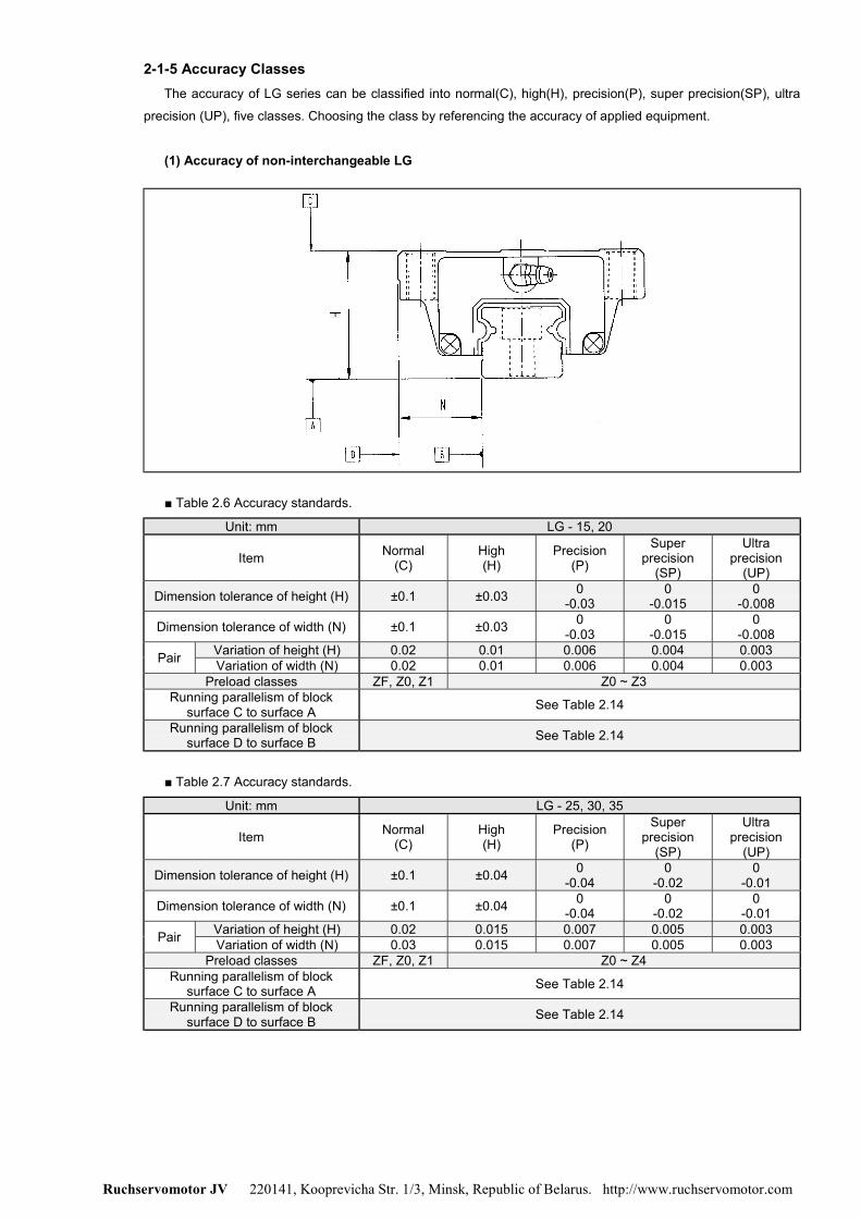
2-1-5 Accuracy ClassesThe accuracy of LG series can be classified into normal(C), high(H), precision(P), super precision(SP), ultra
precision (UP), five classes. Choosing the class by referencing the accuracy of applied equipment.
(1) Accuracy of non-interchangeable LG
■ Table 2.6 Accuracy standards.
Unit: mm LG - 15, 20
Item Normal(C)
High(H)
Precision(P)
Superprecision
(SP)
Ultraprecision
(UP)
Dimension tolerance of height (H) ±0.1 ±0.03 0-0.03
0-0.015
0-0.008
Dimension tolerance of width (N) ±0.1 ±0.03 0-0.03
0-0.015
0-0.008
Variation of height (H) 0.02 0.01 0.006 0.004 0.003Pair Variation of width (N) 0.02 0.01 0.006 0.004 0.003Preload classes ZF, Z0, Z1 Z0 ~ Z3
Running parallelism of blocksurface C to surface A See Table 2.14
Running parallelism of blocksurface D to surface B See Table 2.14
■ Table 2.7 Accuracy standards.
Unit: mm LG - 25, 30, 35
Item Normal(C)
High(H)
Precision(P)
Superprecision
(SP)
Ultraprecision
(UP)
Dimension tolerance of height (H) ±0.1 ±0.04 0-0.04
0-0.02
0-0.01
Dimension tolerance of width (N) ±0.1 ±0.04 0-0.04
0-0.02
0-0.01
Variation of height (H) 0.02 0.015 0.007 0.005 0.003Pair Variation of width (N) 0.03 0.015 0.007 0.005 0.003Preload classes ZF, Z0, Z1 Z0 ~ Z4
Running parallelism of blocksurface C to surface A See Table 2.14
Running parallelism of blocksurface D to surface B See Table 2.14

Ruchservomotor JV 220141, Kooprevicha Str. 1/3, Minsk, Republic of Belarus. http://www.ruchservomotor.com
■ Table 2.8 Accuracy standards.
Unit: mm LG - 45, 55
Item Normal(C)
High(H)
Precision(P)
SuperPrecision
(SP)
Ultraprecision
(UP)
Dimension tolerance of height (H) ±0.1 ±0.05 0-0.05
0-0.03
0-0.02
Dimension tolerance of width (N) ±0.1 ±0.05 0-0.05
0-0.03
0-0.02
Variation of height (H) 0.03 0.015 0.007 0.005 0.003Pair Variation of width (N) 0.03 0.02 0.01 0.007 0.005Preload classes ZF, Z0, Z1 Z0 ~ Z4
Running parallelism of blocksurface C to surface A See Table 2.14
Running parallelism of blocksurface D to surface B See Table 2.14
■ Table 2.9 Accuracy standards.
Unit: mm LG – 65
Item Normal(C)
High(H)
Precision(P)
SuperPrecision
(SP)
Ultraprecision
(UP)
Dimension tolerance of height (H) ±0.1 ±0.07 0-0.07
0-0.05
0-0.03
Dimension tolerance of width (N) ±0.1 ±0.07 0-0.07
0-0.05
0-0.03
Variation of height (H) 0.03 0.02 0.01 0.007 0.005Pair Variation of width (N) 0.03 0.025 0.015 0.01 0.007Preload classes ZF, Z0, Z1 Z0 ~ Z4
Running parallelism of blocksurface C to surface A See Table 2.14
Running parallelism of blocksurface D to surface B See Table 2.14
(2) Accuracy of interchangeable LG
■ Table 2.10 Accuracy standards.
Unit: mm LG – 15, 20
Item Normal(C)
High(H)
Precision(P)
Dimension tolerance of height (H) ±0.1 ±0.03 0-0.03
Dimension tolerance of width (N) ±0.1 ±0.03 0-0.03
Variation of height (H) 0.02 0.01 0.006Pair (one set) Variation of width (N) 0.02 0.01 0.006Pair variation of height (H) (multi sets) 0.06 0.035 0.024
Preload classes ZF, Z0, Z1 Z0, Z1Running parallelism of block surface C to
surface A See Table 2.14
Running parallelism of block surface D tosurface B See Table 2.14

Ruchservomotor JV 220141, Kooprevicha Str. 1/3, Minsk, Republic of Belarus. http://www.ruchservomotor.com
■ Table 2.11 Accuracy standards.
Unit: mm LG – 25, 30, 35
Item Normal(C)
High(H)
Precision(P)
Dimension tolerance of height (H) ±0.1 ±0.04 0-0.04
Dimension tolerance of width (N) ±0.1 ±0.04 0-0.04
Variation of height (H) 0.02 0.015 0.007Pair (one set) Variation of width (N) 0.03 0.015 0.007Pair variation of height (H) (multi sets) 0.06 0.04 0.025
Preload classes ZF, Z0, Z1 Z0, Z1Running parallelism of block surface C to
surface A See Table 2.14
Running parallelism of block surface D tosurface B See Table 2.14
■ Table 2.12 Accuracy standards.
Unit: mm LG – 45, 55
Item Normal(C)
High(H)
Precision(P)
Dimension tolerance of height (H) ±0.1 ±0.05 0-0.05
Dimension tolerance of width (N) ±0.1 ±0.05 0-0.05
Variation of height (H) 0.03 0.015 0.007Pair (one set) Variation of width (N) 0.03 0.02 0.01Pair variation of height (H) (multi sets) 0.07 0.04 0.025
Preload classes ZF, Z0, Z1 Z0, Z1Running parallelism of block surface C to
surface A See Table 2.14
Running parallelism of block surface D tosurface B See Table 2.14
■ Table 2.13 Accuracy standards.
Unit: mm LG – 65
Item Normal(C)
High(H)
Precision(P)
Dimension tolerance of height (H) ±0.1 ±0.07 0-0.07
Dimension tolerance of width (N) ±0.1 ±0.07 0-0.07
Variation of height (H) 0.03 0.02 0.01Pair (one set) Variation of width (N) 0.03 0.025 0.015Pair variation of height (H) (multi sets) 0.07 0.045 0.028
Preload classes ZF, Z0, Z1 Z0, Z1Running parallelism of block surface C to
surface A See Table 2.14
Running parallelism of block surface D tosurface B See Table 2.14

Ruchservomotor JV 220141, Kooprevicha Str. 1/3, Minsk, Republic of Belarus. http://www.ruchservomotor.com
(3) Accuracy of running parallelism
■ Table 2.14 Accuracy of running parallelism.
Accuracy, µmRail length, mm C H P SP UP~ 100 12 7 3 2 2
100 ~ 200 14 9 4 2 2200 ~ 300 15 10 5 3 2300 ~ 500 17 12 6 3 2500 ~ 700 20 13 7 4 2700 ~ 900 22 15 8 5 3
900 ~ 1,100 24 16 9 6 31,100 ~ 1,500 26 18 11 7 41,500 ~ 1,900 28 20 13 8 41,900 ~ 2,500 31 22 15 10 52,500 ~ 3,100 33 25 18 11 63,100 ~ 3,600 36 27 20 14 73,600 ~ 4,000 37 28 21 15 7
2-1-6 Preload
(1) DefinitionA preload can be applied to each guideway. Oversized balls are used. Generally, a linear motion guideway
has a negative clearance between groove and balls in order to improve stiffness and maintain high precision.
Figure shows that rigidity is doubled at the point where the load is 2√2 times the preload and the deflection is
one half.
(1) Preload classesHIWIN offers six standard preloads for various applications and conditions.
■ Table 2.15 Preload classes.
Class Code Preload Accuracy Examples of applicationLight
clearanceZF Clearance
4 ~ 10 µmC Automation industry
Very lightclearance
Z0 0 C ~ UP Transportation devices, auto-packing machines
Lightpreload
Z1 0.02C C ~ UP X-Y axis for general industrial machines, weldingmachines, welders
Mediumpreload
Z2 0.05C H ~ UP Z axis for general industrial machines, EDM, NClathes, precision X-Y tables, measuring equipment
Heavypreload
Z3 0.07C H ~ UPMachining centres, grinding machines, NC lathes,horizontal and vertical milling machines, Z axis of
machine toolsSuper heavy
preloadZ4 0.13C H ~ UP Heavy cutting machines
Note: The C in preload column means basic dynamic load rating.

Ruchservomotor JV 220141, Kooprevicha Str. 1/3, Minsk, Republic of Belarus. http://www.ruchservomotor.com
2-1-7 Stiffness
To confirm the impact on accuracy, Table 2.16 could be used to calculate the deflection of linear guideway.
kP=δ ……………………Eq. 2.1
δ: Deflection
P: Working load (kgf)
K: Value of rigidity
■ Table 2.16 Value of rigidity.
Type Size Z0kgf/mm
Z1kgf/mm
Z2kgf/mm
Z3kgf/mm
Z4kgf/mm
LG15-C 19 24 28 30 -LG20-C 26 33 38 41 -LG25-C 28 36 42 45 52LG30-C 35 45 52 56 65LG35-C 41 52 60 65 74LG45-C 50 64 74 79 92LG55-C 58 74 86 92 106
Heavyload
LG65-C 70 89 104 111 128LG20-C 32 41 47 51 -LG25-C 37 47 54 58 67LG30-C 45 57 66 70 81LG35-C 51 65 76 81 94LG45-C 65 83 96 103 118LG55-C 75 96 111 119 137
Superheavy load
LG65-C 92 117 135 145 167
2-1-8 Lubrication
(1) Grease
► 1 Grease nipple

Ruchservomotor JV 220141, Kooprevicha Str. 1/3, Minsk, Republic of Belarus. http://www.ruchservomotor.com
► 2 Mounting location
The standard location of the grease fitting is at both ends of the block, but the nipple may optionally be
mounted in the side of block. As for the lateral installation, we recommended that the nipple should be
mounted at the non-reference side, otherwise please contact us. It is possible to carry out the lubrication
by using the oil-piping joint.
► 3 The oil amount for a block full with grease
■ Table 2.17 The oil amount for a block full with grease.
Size Heavy load(cm3)
Super heavy load(cm3)
Size Heavy load(cm3)
Super heavy load(cm3)
LG15 1 - LG35 10 12LG20 2 3 LG45 17 21LG25 5 6 LG55 26 33LG30 7 8 LG65 50 61
► 4 Frequency of replenishment
Replenishing the oil every 100 km.
(2) Oil
The recommended viscosity of oil is about 30~150 cst. If customers need to use the oil-type lubrication,
please inform us, the block will not be prelubricated with grease before shipment.
► 1 Types of oil piping joint

Ruchservomotor JV 220141, Kooprevicha Str. 1/3, Minsk, Republic of Belarus. http://www.ruchservomotor.com
► 2 Oil feeding rate
■ Table 2.18 Oil feeding rate.
Size Feeding rate (cm3/hr) Size Feeding rate (cm3/hr)LG15 0.2 LG35 0.3LG20 0.2 LG45 0.4LG25 0.3 LG55 0.5LG30 0.3 LG65 0.6
2-1-9 Dust Protection Equipment
(1) Code of equipmentIf the following equipment needed, please indicate the code followed by the model number.
No code (standard): (End seal + Bottom seal) ZZ (End seal + Bottom seal + Scraper)
KK (Double seals + Bottom seal + Scraper) DD (Double seals + Bottom seal)
(2) End seal and bottom sealTo prevent of life reduction due to the groove surface damaged by iron chips or dust entering the block.
(3) Double sealsEnhancing the wiping effect, the foreign matters can be completely wiped out of block.
■ Table 2.19 Order number of end seal.
Size Part No. Thickness t1, mm Size Part No. Thickness t1, mmLG15 920001A1 1.8 LG35 920005A1 2.8LG20 920002A1 2 LG45 920006A1 3.5LG25 920003A1 2.5 LG55 920007A1 5LG30 920004A1 2.8 LG65 920008A1 5

Ruchservomotor JV 220141, Kooprevicha Str. 1/3, Minsk, Republic of Belarus. http://www.ruchservomotor.com
(4) ScraperThe scraper have the ability of isolating the high-temp iron chips and removing the big foreign matters.
■ Table 2.20 Order number of scraper.
Size Part No. Thickness t2, mm Size Part No. Thickness t2, mmLG15 980001A1 1.5 LG35 980005A1 1.5LG20 980002A1 1.5 LG45 980006A1 1.5LG25 980003A1 1.5 LG55 980007A1 1.7LG30 980004A1 1.5 LG65 980008A1 1.7
(5) Caps for rail mounting holesThe caps are used to cover the mounting holes to prevent chips or other foreign matters from entering the
holes. The caps will be enclosed in each rail packing
■ Table 2.21 Caps for rail mounting holes.
Rail size Bolt size Part No. Diameter D, mm Thickness H, mmLGR 15 M4 950002A1 7.7 1.1LGR 20 M5 950003A1 9.7 2.2LGR 25 M6 950004A1 11.3 2.5LGR 30 M8 950005A1 14.3 3.3LGR 35 M8 950005A1 14.3 3.3LGR 45 M12 950007A1 20.4 4.6LGR 55 M14 950008A1 23.5 5.5LGR 65 M16 950009A1 26.6 5.5
2-1-10 Friction
The maximum value of seal resistance per block are shown in the table.
■ Table 2.22 Seal resistance.
Size Coefficient of friction Resistance, kgf Size Coefficient of friction Resistance, kgfLG15 0.003 0.3 LG35 0.004 0.8LG20 0.003 0.4 LG45 0.005 1LG25 0.003 0.5 LG55 0.005 1.2LG30 0.004 0.7 LG65 0.005 1.5

Ruchservomotor JV 220141, Kooprevicha Str. 1/3, Minsk, Republic of Belarus. http://www.ruchservomotor.com
2-1-11 The Accuracy Tolerance of Mounting Surface
(1) The accuracy tolerance of rail-mounting surface
Because of the Gothic contact design, the linear guideway is possessed with high rigidity. As for this
characteristic, any unreasonable deviation will not only increase the friction resistance, but also reduce the life.
As long as following the accuracy requirements of mounting surface, the high accuracy and rigidity of
linear motion guideway should be obtained without any difficulty.
In order to satisfy the needs of fast installation and smooth movement, HIWIN offers the normal clearance
type of preload to customers for its high absorption ability for the deviation of mounting surface accuracy.
► 1 The parallelism tolerance of reference surface (P)
■ Table 2.23 Max. parallelism tolerance (P).
Preload classesSize
ZF Z0 Z1 Z2 Z3 Z4LG15 0.023 0.014 0.010 0.007 0.005 -LG20 0.026 0.016 0.011 0.008 0.006 0.005LG25 0.028 0.017 0.012 0.009 0.007 0.006LG30 0.032 0.021 0.015 0.012 0.009 0.007LG35 0.035 0.023 0.017 0.014 0.011 0.008LG45 0.040 0.027 0.020 0.016 0.013 0.010LG55 0.050 0.036 0.026 0.020 0.017 0.012LG65 0.060 0.045 0.032 0.025 0.021 0.015
► 2 The accuracy tolerance of reference surface height (S1)
KaS1 ×= ……………………………………………..………Eq. 2.2
S1: Max. tolerance of height
a: Distance between paired rails
K: Coefficient of tolerance of height
■ Table 2.24 Max. tolerance of height.
Preload classesCoefficient oftolerance of height ZF Z0 Z1 Z2 Z3 Z4
K 5.5×10⁻⁴ 4.1×10⁻⁴ 2.7×10⁻⁴ 2.2×10⁻⁴ 1.7×10⁻⁴ 1.2×10⁻⁴

Ruchservomotor JV 220141, Kooprevicha Str. 1/3, Minsk, Republic of Belarus. http://www.ruchservomotor.com
(2) The accuracy tolerance of block-mounting surface
► 1 The tolerance of height of reference surface when two or more pieces are used in parallel (S2)
52 102.4bS −××= ……………………………………………..………Eq. 2.3
S2: Max. tolerance of height
b Distance between paired blocks
► 2 The accuracy tolerance of mounting reference surface for paired blocks at the rail (S3)
53 102.4cS −××= ……………………………………………..………Eq. 2.4
S3: Max. tolerance of height
c Distance between paired blocks
12-1-12 Cautions for Installation
(1) Shoulder heights and filletsThe improper shoulder heights and fillets of mounting surfaces will cause the deviation of accuracy and the
interference with the chamfered part of the rail or block. As long as following the recommended shoulder
heights and fillets, the accuracy problem of installation should be eliminated.

Ruchservomotor JV 220141, Kooprevicha Str. 1/3, Minsk, Republic of Belarus. http://www.ruchservomotor.com
■ Table 2.25 Shoulder heights and fillets.
Size Max. radius of filletsr, mm
Shoulder height of the railH1, mm
Shoulder height of the blockH2, mm
LG15 0.3 3 4LG20 0.3 4 5LG25 0.5 5 5LG30 0.5 5 5LG35 0.5 6 6LG45 1 8 6LG55 1.5 10 10LG65 1.5 10 10
(2) Tightening torque of bolts for installationThe improper tightening of bolts will influence the accuracy of Linear Guideway seriously, so that the
following tightening torque for different sizes of bolt is recommended.
■ Table 2.26 Torque.
Size Bolt size Torque, kgf-cm Size Bolt size Torque, kgf-cmLG15 M4×0.7P×16L 40 LG35 M8×1.25P×25L 640LG20 M5×0.8P×16L 90 LG45 M12×1.75P×35L 1200LG25 M6×1P×20L 140 LG55 M14×2P×45L 1600LG30 M8×1.25P×25L 310 LG65 M16×2P×50L 2000
2-1-13 Standard Length and Max. Length of Rail
HIWIN has offered the standard length of rails for customer needs. As for the non-standard E value, to avoid
the unstable end part of rail, it is recommended the E value should not be over 1/2 of pitch (P). On the other hand,
the E value should not be less than the Emin due to the break of mounting hole.
E2P)1n(L ×+×−= ……………………………………………..………Eq. 2.5
L: Total length of rail (mm)
n: Number of mounting holes
P: Distance between any two holes (mm)
E: Distance from the centre of the last hole to the edge (mm)

Ruchservomotor JV 220141, Kooprevicha Str. 1/3, Minsk, Republic of Belarus. http://www.ruchservomotor.com
■ Table 2.27 Rail length.
Size, mmItem
LG15 LG20 LG25 LG30 LG35 LG45 LG55 LG65160(3) 220(4) 220(4) 280(4) 280(4) 570(6) 780(7) 1,270(9)220(4) 280(5) 280(5) 440(6) 440(6) 885(9) 1,020(9) 1,570(11)280(5) 340(6) 340(6) 600(8) 600(8) 1,200(12) 1,260(11) 2,020(14)340(6) 460(8) 460(8) 760(10) 760(10) 1,620(16) 1,500(13) 2,620(18)460(8) 640(11) 640(11) 1,000(13) 1,000(13) 2,040(20) 1,980(17)
640(11) 820(14) 820(14) 1,640(21) 1,640(21) 2,460(24) 2,580(22)820(14) 1,000(17) 1,000(17) 2,040(26) 2,040(26) 2,985(29) 2,940(25)
1,240(21) 1,240(21) 2,520(32) 2,520(32)
Standard lengthL(n)
1,600(27) 3,000(38) 3,000(38)Pitch P 60 60 60 80 80 105 120 150
Standard distanceto end Es
20 20 20 20 20 22.5 30 35
Min. distance toend Emin
10 10 10 12 12 16 18 20
Max. rail length 2,980(50) 4,000(67) 4,000(67) 3,960(50) 3,960(50) 3,930(38) 3,900(33) 3,970(27)
Note: 1. Tolerance of E value for standard rails is 0.5 ~ -0.5mm. Tolerance of E value for butt-joint rails
is 0 ~ -0.3mm.
2. Maximum standard length means the max. rail length with standard E value on both side.
Ruchservomotor JV 220141, Kooprevicha Str. 1/3, Minsk, Republic of Belarus. http://www.ruchservomotor.com
2-1-14 Dimensions for HIWIN LG Series (1) LGH-CA / LGH-HA
WeightDimensions ofAssembly
(mm)
Dimensions of Block(mm)
Dimensions of Rail(mm)
MountingBolt
for Rail(mm)
BasicDynamic
LoadRating(kgf)
BasicStaticLoad
Rating(kgf)
Static RatedMoment(kgf-m) Block
(kg)Rail
(kg/m)Model No.
H H1 N W B B1 C L1 L G M×ℓ T H2 Wr Hr D h d P E C C0 M0 Mx My
LGH15-CA 28 4.5 9.5 34 26 4 26 39.6 60.6 3.8 M4×5 6 8.5 15 14 7.5 5.3 4.5 60 20 M4×16 1040 1,680 13.5 11.0 11.0 0.21 1.47LGH20-CA 36 52.7 77.3 1650 2670 28.1 22.8 22.8 0.37LGH20-HA
30 5 12 44 32 650 67 91.6
12 M5×6 8 7.1 20 15 9.5 8.5 6 60 20 M5×16 2100 3400 35.7 35.9 35.9 0.462.08
LGH25-CA 35 57.6 85.6 2410 3880 46.6 37.2 37.2 0.59LGH25-HA
40 6.5 12.5 48 35 6.550 76.6 104.6
12 M6×8 8 11.2 23 20 11 9 7 60 20 M6×20 3210 5180 62.2 63.6 63.6 0.783.15
LGH30-CA 40 72 104.4 3380 5460 79.3 61.2 61.2 1.04LGH30-HA
45 7 16 60 40 1060 93 125.4
12 M8×10 8 10.5 28 23 14 12 9 80 20 M8×254400 7100 103.0 100.4 100.4 1.33
4.41
LGH35-CA 50 82 118.4 4180 6740 118.1 84.4 84.4 1.72LGH35-HA
55 8 18 70 50 1072 105.8 142.2
12 M8×12 10 15 34 25 14 12 9 80 20 M8×255430 8770 153.5 138.4 138.4 2.24
5.93
LGH45-CA 60 99.6 139.2 6020 9710 223.5 141.3 141.3 3.16LGH45-HA
70 10 20.5 86 60 1380 133 172.6
12.9 M10×17 15 21 45 32 20 17 14 105 22.5 M12×358430 13600 312.8 259.2 259.2 4.28
10.01
LGH55-CA 75 115.8 164.8 9740 13220 384.9 280.9 280.9 5.30LGH55-HA
80 13 23.5 100 75 12.595 154.7 203.7
12.9 M12×18 17 22 53 40 23 20 16 120 30 M14×45 11810 18510 489.8 442.7 442.7 6.4014.82
LGH65-CA 70 138.6 197.6 14940 20990 738.8 579.0 579.0 7.30LGH65-HA
90 19 31.5 126 76 25120 187.6 246.6
12.9 M16×20 25 20 63 48 26 22 18 150 35 M16×50 18290 27290 1007.5 1040.8 1040.8 9.3021.26
Note: Above listed dimensions of rail are dimensions of LGR-R (Bolt hole, mounting from above); and dimensions of LGR-T (Tapped hole, mounting from below) refer to page 37.

Ruchservomotor JV 220141, Kooprevicha Str. 1/3, Minsk, Republic of Belarus. http://www.ruchservomotor.com
(2) LGW-CA / LGW-HA
WeightDimensions ofAssembly
(mm)
Dimensions of Block(mm)
Dimensions of Rail(mm)
MountingBolt
for Rail(mm)
BasicDynamic
LoadRating(kgf)
BasicStaticLoad
Rating(kgf)
Static RatedMoment(kgf-m) Block
(kg)Rail
(kg/m)Model No.
H H1 N W B B1 C L1 L G M T T1 H2 H3 Wr Hr D h d P E C C0 M0 Mx My
LGW15-CA 24 4.5 16 47 38 4.5 30 39.6 60.6 3.8 M5 6 9 4.5 3.6 15 14 7.5 5.3 4.5 60 20 M4×16 1040 1680 13.5 11.0 11.0 0.20 1.47LGW20-CA 52.7 77.3 1650 2670 28.1 22.8 22.8 0.46LGW20-HA
30 5 21.5 63 53 5 4067 91.6
12 M6 8 10 7.1 7.1 20 15 9.5 8.5 6 60 20 M5×16 2100 3400 35.7 35.9 35.9 0.582.08
LGW25-CA 57.6 85.6 2410 3880 46.6 37.2 37.2 0.64LGW25-HA
36 6.5 23.5 70 57 6.5 4576.6 104.6
12 M8 8 14 7.2 7 23 20 11 9 7 60 20 M6×20 3210 5180 62.2 63.6 63.6 0.863.15
LGW30-CA 72 104.4 3380 5460 79.3 61.2 61.2 1.20LGW30-HA
42 7 31 90 72 9 5293 125.4
12 M10 8 16 7.5 7.5 28 23 14 12 9 80 20 M8×25 4400 7100 103.0 100.4 100.4 1.564.41
LGW35-CA 82 118.4 4180 6740 118.1 84.4 84.4 1.78LGW35-HA
48 8 33 100 82 9 62105.8 142.2
12 M10 10 18 8 9 34 25 14 12 9 80 20 M8×25 5430 8770 153.5 138.4 138.4 2.345.93
LGW45-CA 99.6 139.2 6020 9710 223.5 141.3 141.3 3.13LGW45-HA
60 10 37.5 120 100 10 80133 172.6
12.9 M12 15 22 11 11 45 32 20 17 14 105 22.5 M12×358430 13600 312.8 259.2 259.2 4.27
10.01
LGW55-CA 115.8 164.8 9740 13220 384.9 280.9 280.9 5.50LGW55-HA
70 13 43.5 140 116 12 95154.7 203.7
12.9 M14 17 26 12 12 53 40 23 20 16 120 30 M14×4511810 18510 489.8 442.7 442.7 6.70
14.82
LGW65-CA 138.6 197.6 14940 20990 738.8 579.0 579.0 8.50LGW65-HA
90 19 53.5 170 142 14 110187.6 246.6
12.9 M16 23 37 20 20 63 48 26 22 18 150 35 M16×5018290 27290 1007.5 1040.8 1040.8 10.70
21.26
Note: Above listed dimensions of rail are dimensions of LGR-R (Bolt hole, mounting from above); and dimensions of LGR-T (Tapped hole, mounting from below) refer to page 37.
Ruchservomotor JV 220141, Kooprevicha Str. 1/3, Minsk, Republic of Belarus. http://www.ruchservomotor.com
(3) LGW-CB / LGW-HB
WeightDimensions ofAssembly
(mm)
Dimensions of Block(mm)
Dimensions of Rail(mm)
MountingBolt
for Rail(mm)
BasicDynamic
LoadRating(kgf)
BasicStaticLoad
Rating(kgf)
Static RatedMoment(kgf-m) Block
(kg)Rail
(kg/m)Model No.
H H1 N W B B1 C L1 L G M T T1 T2 H2 H3 Wr Hr D h d P E C C0 M0 Mx My
LGW15-CB 24 4.5 16 47 38 4.5 30 39.6 60.6 3.8 Ø4.5 6 9 7 4.5 3.6 15 14 7.5 5.3 4.5 60 20 M4×16 1040 1680 13.5 11.0 11.0 0.20 1.47LGW20-CB 52.7 77.3 1650 2670 28.1 22.8 22.8 0.46LGW20-HB
30 5 21.5 63 53 5 4067 91.6
12 Ø6 8 10 10 7.1 7.1 20 15 9.5 8.5 6 60 20 M5×162100 3400 35.7 35.9 35.9 0.58
2.08
LGW25-CB 57.6 85.6 2410 3880 46.6 37.2 37.2 0.64LGW25-HB
36 6.5 23.5 70 57 6.5 4576.6 104.6
12 Ø7 8 14 10 7.2 7 23 20 11 9 7 60 20 M6×203210 5180 62.2 63.6 63.6 0.86
3.15
LGW30-CB 72 104.4 3380 5460 79.3 61.2 61.2 1.20LGW30-HB
42 7 31 90 72 9 5293 125.4
12 Ø9 8 16 10 7.5 7.5 28 23 14 12 9 80 20 M8×25 4400 7100 103.0 100.4 100.4 1.564.41
LGW35-CB 82 118.4 4180 6740 118.1 84.4 84.4 1.78LGW35-HB
48 8 33 100 82 9 62105.8 142.2
12 Ø9 10 18 13 8 9 34 25 14 12 9 80 20 M8×25 5430 8770 153.5 138.4 138,4 2.345.93
LGW45-CB 99.6 139.2 6020 9710 223.5 141.3 141.3 3.13LGW45-HB
60 10 37.5 120 100 10 80133 172.6
12.9 Ø11 15 22 15 11 11 45 32 20 17 14 105 22.5 M12×35 8430 13600 312.8 259.2 259.2 4.2710.01
LGW55-CB 115.8 164.8 9740 13220 384.9 280.9 280.9 5.50LGW55-HB
70 13 43.5 140 116 12 95154.7 203.7
12.9 Ø14 17 26 17 12 12 53 40 23 20 16 120 30 M14×45 11810 18510 489.8 442.7 442.7 6.7014.82
LGW65-CB 138.6 197.6 14940 20990 738.8 579.0 579.0 8.50LGW65-HB
90 19 53.5 170 142 14 110187.6 246.6
12.9 Ø16 23 37 23 20 20 63 48 26 22 18 150 35 M16×5018290 27290 1007.5 1040.8 1040.8 10.70
21.26
Note: Above listed dimensions of rail are dimensions of LGR-R (Bolt hole, mounting from above); and dimensions of LGR-T (Tapped hole, mounting from below) refer to page 37.

Ruchservomotor JV 220141, Kooprevicha Str. 1/3, Minsk, Republic of Belarus. http://www.ruchservomotor.com
(4) LGW-CC / LGW-HC
WeightDimensions ofAssembly
(mm)
Dimensions of Block(mm)
Dimensions of Rail(mm)
MountingBolt
for Rail(mm)
BasicDynamic
LoadRating(kgf)
BasicStaticLoad
Rating(kgf)
Static RatedMoment(kgf-m) Block
(kg)Rail
(kg/m)Model No.
H H1 N W B B1 C L1 L G M T T1 T2 H2 H3 Wr Hr D h d P E C C0 M0 Mx My
LGW15-CC 24 4.5 16 47 38 4.5 30 39.6 60.6 5.3 M5 6 9 7 4.5 3.6 15 14 7.5 5.3 4.5 60 20 M4X16 1040 1680 13.5 11.0 11.0 0.20 1.47LGW25-CC 57.6 85.6 2410 3880 46.6 37.2 37.2 0.64LGW25-HC
36 6.5 23.5 70 57 6.5 4576.6 104.6
12 M8 8 14 10 8.8 7 23 20 11 9 7 60 20 M6X203210 5180 62.2 63.6 63.6 0.86
3.15
LGW30-CC 72 104.4 3380 5460 79.3 61.2 61.2 1.20LGW30-HC
42 7 31 90 72 9 5293 125.4
12 M10 8 16 10 11 7.5 28 23 14 12 9 80 20 M8X254400 7100 103.0 100.4 100.4 1.56
4.41
LGW35-CC 82 118.4 4180 6740 118.1 84.4 84.4 1.78LGW35-HC
48 8 33 100 82 9 62105.8 142.2
12 M10 10 18 13 14.4 9 34 25 14 12 9 80 20 M8X255430 8770 153.5 138.4 138.4 2.34
5.93
LGW45-CC 99.6 139.2 6020 9710 223.5 141.3 141.3 3.13LGW45-HC
60 10 37.5 120 100 10 80133 172.6
12.9 M12 15 22 15 18.2 11 45 32 20 17 14 105 22.5 M12X358430 13600 312.8 259.2 259.2 4.27
10.01
LGW55-CC 115.8 164.8 9740 13220 384.9 280.9 280.9 5.50LGW55-HC
70 13 43.5 140 116 12 95154.7 203.7
12.9 M14 17 26 18 12 12 53 40 23 20 16 120 30 M14X4511810 18510 489.8 442.7 442.7 6.70
14.82
LGW65-CC 138.6 197.6 14940 20990 738.8 579.0 579.0 8.50LGW65-HC
90 19 53.5 170 142 14 110187.6 246.6
12.9 M16 23 37 23 20 20 63 48 26 22 18 150 35 M16X5018290 27290 1007.5 1040.8 1040.8 10.70
21.26
Note: Above listed dimensions of rail are dimensions of LGR-R (Bolt hole, mounting from above); and dimensions of LGR-T (Tapped hole, mounting from below) refer to page 37.
Ruchservomotor JV 220141, Kooprevicha Str. 1/3, Minsk, Republic of Belarus. http://www.ruchservomotor.com
(5) Dimensions for LGR-T (Rail mounting from below)
Dimensions of rail (mm)Model No.
WR HR S h P EWeight(kg/m)
LGR15-T 15 14 M5×0.8P 7.5 60 20 1.59LGR20-T 20 15 M6×1P 8 60 20 2.26LGR25-T 23 20 M6×1P 12 60 20 3.41LGR30-T 28 23 M8×1.25P 15 80 20 4.76LGR35-T 34 25 M8×1.25P 16 80 20 6.31LGR45-T 45 32 M12×1.75P 20 105 22.5 10.70LGR55-T 53 40 M14×2P 24 120 30 15.52LGR65-T 63 48 M20×2.5P 30 150 35 21.82

Ruchservomotor JV 220141, Kooprevicha Str. 1/3, Minsk, Republic of Belarus. http://www.ruchservomotor.com
2-2 AG Series
2-2-1 Features of the AG Series Linear GuidewayBecause of enlarged balls and Gothic contact design, AG series is possessed with stiffness, accuracy, and
loading capacity. Besides these characteristics, the lower assembly height and the shorter length make the AG
series more suitable for the high-speed automatic machines and the applications where space limit is considered.
Moreover, the optimum design of circulating system makes the AG series moving smoothly and quietly even
under the high-speed condition.
2-2-2 Construction of AG Series
● Rolling circulating system: Block, rail, end plate and retainer.
● Lubrication system: Grease nipple and piping joint.
● Dust protection system: End seal, bottom seal, cap, double seals and scraper.
2-2-3 Model Number of AG SeriesAG series guideway can be classified into non-interchangeable and interchangeable types. The size of two
types is same as each other. The main difference between two types is that the interchangeable type of blocks
and rails can be freely exchanged, and their accuracy can reach up to P class. Because of the restrictedly
dimensional control, the interchangeable type linear guideway is a smart choice for customer when rails don't
need to be paired for an axis. The model number of AG series contains the size, type, accuracy class, preload
class, etc..

Ruchservomotor JV 220141, Kooprevicha Str. 1/3, Minsk, Republic of Belarus. http://www.ruchservomotor.com
(1) Non-interchangeable type
AG W 25 C A E 2 R 1600 E Z1 P II + DD / E1● AG series
● Block typeW: Flange typeH: Square type
● Model size15, 20, 25, 30
● Load typeS: Medium load; C: Heavy load
● Block mounting typeA: Mounting from above;B: Below; C: Above or below
● Block special option
● No. of blocks per rail
● Optional functionE1: Self lubricantSE: Heat resistant
● Dust protection2
● No. of rails per axis1
● Precision code: C, H, P, SP, UP
● Preload code: ZF, Z0, Z1 ~ Z3
● Rail special option
● Rail length (mm)
● Rail mounting typeR/U: Mounting from above, T: Below
Note: 1. The Roman numerals used to express the number of rails used in one axis. As for the single rail inan axis, it shows no symbol.
2. For dust protection, it is no symbol if it is standard (end seal and bottom seal).ZZ: End seal, bottom seal and scraper.KK: Double seals, bottom seal and scraper.DD: Double seals and bottom seal.
(2) Interchangeable type● Model number of AG block
AG W 25 C A E Z1 P + DD / E1● AG series
● Block typeW: Flange typeH: Square type
● Model size15, 20, 25, 30
● Load typeS: Medium load; C: Heavy load
● Block mounting typeA: Mounting from above;B: Below; C: Above or below
● Optional functionE1: Self lubricantSE: Heat resistant
● Dust protection2
● Precision code: C, H, P
● Preload code: ZF, Z0, Z1
● Block special option
● Model number of AG rail
AG R 25 R 1600 E P● AG series
● Interchangeable rail
● Model size15, 20, 25, 30
● Rail mounting typeR/U: Mounting from above; T: Below
● Precision code: C, H, P
● Rail special option
● Rail length (mm)

Ruchservomotor JV 220141, Kooprevicha Str. 1/3, Minsk, Republic of Belarus. http://www.ruchservomotor.com
2-2-4 Types
(1) Block types
HIWIN offers two types of linear guideway which are flange and square types. Because of the low
assembly height and larger mounting surface, the flange type is good for heavy moment load application.
■ Table 2.28 Block types.
Type Model Shape Height, mm Rail length, mm
SquareAGH-SAAGH-CA 24 ~ 42 100 ~ 4000
AGW-SAAGW-CA 24 ~ 42 100 ~ 4000
Flange
AGW-SBAGW-CB 24 ~ 42 100 ~ 4000
(2) Rail types
Besides the standard top-mounting type, HIWIN also offers the bottom mounting type of rails to customers.
■ Table 2.29 Rail types.
Mounting from above Mounting from below

Ruchservomotor JV 220141, Kooprevicha Str. 1/3, Minsk, Republic of Belarus. http://www.ruchservomotor.com
2-2-5 Accuracy ClassesThe accuracy of AG series can be classified into normal (C), high (H), precision (P), super precision (SP), ultra
precision (UP), five classes. Choosing the class by referencing the accuracy of applied equipment.
(1) Accuracy of non-interchangeable AG
■ Table 2.30 Accuracy standards.
Unit: mm AG - 15, 20
Item Normal(C)
High(H)
Precision(P)
Superprecision
(SP)
Ultraprecision
(UP)
Dimension tolerance of height H ±0.1 ±0.03 0-0.03
0-0.015
0-0.008
Dimension tolerance of width N ±0.1 ±0.03 0-0.03
0-0.015
0-0.008
Variation of height H 0.02 0.01 0.006 0.004 0.003Pair Variation of width N
(master rail) 0.02 0.01 0.006 0.004 0.003
Preload classes ZF, Z0, Z1 Z0 ~ Z3Running parallelism of block
surface C to surface A See Table 2.34
Running parallelism of blocksurface D to surface B See Table 2.34
■ Table 2.31 Accuracy standards.
Unit: mm AG - 25, 30
Item Normal(C)
High(H)
Precision(P)
Superprecision
(SP)
Ultraprecision
(UP)
Dimension tolerance of height H ±0.1 ±0.04 0-0.04
0-0.02
0-0.01
Dimension tolerance of width N ±0.1 ±0.04 0-0.04
0-0.02
0-0.01
Variation of height H 0.02 0.015 0.007 0.005 0.003Pair Variation of width N
(master rail) 0.03 0.015 0.007 0.005 0.003
Preload classes ZF, Z0, Z1 Z0 ~ Z4Running parallelism of block
surface C to surface A See Table 2.34
Running parallelism of blocksurface D to surface B See Table 2.34

Ruchservomotor JV 220141, Kooprevicha Str. 1/3, Minsk, Republic of Belarus. http://www.ruchservomotor.com
(2) Accuracy of interchangeable AG
■ Table 2.32 Accuracy standards.
Unit: mm AG – 15, 20
Item Normal(C)
High(H)
Precision(P)
Dimension tolerance of height H ±0.1 ±0.03 ±0.015Dimension tolerance of width N ±0.1 ±0.03 ±0.015
Variation of height H 0.02 0.01 0.006Pair Variation of width N 0.02 0.01 0.006Pair variation of height H (multi sets) 0.06 0.04 0.026
Preload classes ZF, Z0, Z1 Z0, Z1Running parallelism of block surface C to
surface A See Table 2.34
Running parallelism of block surface D tosurface B See Table 2.34
■ Table 2.33 Accuracy standards.
Unit: mm AG – 25, 30
Item Normal(C)
High(H)
Precision(P)
Dimension tolerance of height H ±0.1 ±0.04 ±0.02Dimension tolerance of width N ±0.1 ±0.04 ±0.02
Variation of height H 0.02 0.015 0.007Pair Variation of width N 0.03 0.015 0.007Pair variation of height H (multi sets) 0.06 0.045 0.027
Preload classes ZF, Z0, Z1 Z0, Z1Running parallelism of block surface C to
surface A See Table 2.14
Running parallelism of block surface D tosurface B See Table 2.14
(3) Accuracy of running parallelism
■ Table 2.34 Accuracy of running parallelism, µm.
Preload classesRail length, mm C H P SP UP~ 100 12 7 3 2 2
100 ~ 200 14 9 4 2 2200 ~ 300 15 10 5 3 2300 ~ 500 17 12 6 3 2500 ~ 700 20 13 7 4 2700 ~ 900 22 15 8 5 3
900 ~ 1,100 24 16 9 6 31,100 ~ 1,500 26 18 11 7 41,500 ~ 1,900 28 20 13 8 41,900 ~ 2,500 31 22 15 10 52,500 ~ 3,100 33 25 18 11 63,100 ~ 3,600 36 27 20 14 73,600 ~ 4,000 37 28 21 15 7

Ruchservomotor JV 220141, Kooprevicha Str. 1/3, Minsk, Republic of Belarus. http://www.ruchservomotor.com
2-2-6 PreloadAG series provide five standard preloads for various applications. Although increasing the preload is a good
way to get higher stiffness, for avoiding the reduction of service life, we suggest the preload of AG15, 20 should
not over medium class.
■ Table 2.15 Preload classes.
Class Code Preload AccuracyLight clearance ZF Clearance 4 ~ 10 µm C
Very light clearance Z0 0 C ~ UPLight preload Z1 0.02C C ~ UP
Medium preload Z2 0.05C H ~ UPHeavy preload Z3 0.07C H ~ UP
NOTE: The C in preload column means basic dynamic load rating.
2-2-7 StiffnessTo confirm that whether the rigidity will affect the accuracy or not, the rigidity corresponding to the preload
amount.
kP=δ ……………………Eq. 2.6
δ: Deflection (µm)
P: Working load (kgf)
k: Value of rigidity
■ Table 2.36 Value of rigidity.
Type Size Z0kgf/µm
Z1kgf/µm
Z2kgf/µm
Z3kgf/µm
AG15-S 10 13 15 16AG20-S 11 14 16 17AG25-S 14 17 20 22
Heavy load
AG30-S 16 20 23 24AG15-C 16 20 24 25AG20-C 19 24 28 29AG25-C 25 31 36 39
Super heavy load
AG30-C 28 36 41 44
2-2-8 Lubrication
(1) Grease
► 1 Grease nipple

Ruchservomotor JV 220141, Kooprevicha Str. 1/3, Minsk, Republic of Belarus. http://www.ruchservomotor.com
► 2 Mounting location
The standard location of the grease fitting is at both ends of the block, but the nipple may optionally be
mounted in the side of block. As for the lateral installation, we recommended that the nipple should be
mounted at the non-reference side, otherwise please contact us. It is possible to carry out the lubrication
by using the oil-piping joint.
► 3 The oil amount for a block full with grease
■ Table 2.37 The oil amount for a block full with grease.
Size Medium load(cm3)
Heavy load(cm3)
Size Medium load(cm3)
Heavy load(cm3)
AG15 0.5 0.6 AG25 1.7 2.1AG20 0.9 1.1 AG30 3.8 4.4
► 4 Frequency of replenishment
Replenishing the oil every 100 km.
(2) OilThe recommended viscosity of oil is about 30~150 cst. If customers need to use the oil-type lubrication,
please inform us, the block will not be prelubricated with grease before shipment.
► 1 Types of oil piping joint
► 2 Oil feeding rate
■ Table 2.38 Oil feeding rate.
Size Feeding rate (cm3/hr) Size Feeding rate (cm3/hr)AG15 0.2 AG25 0.3AG20 0.2 AG30 0.3
Ruchservomotor JV 220141, Kooprevicha Str. 1/3, Minsk, Republic of Belarus. http://www.ruchservomotor.com
2-2-9 Dust Protection Equipment
(1) Code of equipmentIf the following equipment needed, please indicate the code followed by the model number.
No code (standard): (End seal + Bottom seal) ZZ (End seal + Bottom seal + Scraper)
KK (Double seals + Bottom seal + Scraper) DD (Double seals + Bottom seal)
(2) End seal and bottom sealTo prevent of life reduction due to the groove surface damaged by iron chips or dust entering the block.
(3) Double sealsEnhancing the wiping effect, the foreign matters can be completely wiped out of block.
■ Table 2.39 Order number of end seal.
Size Part No. Thickness t1, mm Size Part No. Thickness t1, mmAG15 92000FA1 1.8 AG25 92000HA1 3AG20 92000GA1 2 AG30 92000IA1 3.2
(4) ScraperThe scraper have the ability of isolating the high-temp iron chips and removing the big foreign matters.
■ Table 2.40 Order number of scraper.
Size Part No. Thickness t2, mm Size Part No. Thickness t2, mmAG15 980009A1 1.5 AG25 98000BA1 1.5AG20 98000AA1 1.5 AG30 98000CA1 1.5

Ruchservomotor JV 220141, Kooprevicha Str. 1/3, Minsk, Republic of Belarus. http://www.ruchservomotor.com
(5) Caps for rail mounting holesThe caps are used to cover the mounting holes to prevent chips or other foreign matters from entering the
holes. The caps will be enclosed in each rail packing
■ Table 2.41 Caps for rail mounting holes.
Rail size Bolt size Part No. Diameter D, mm Thickness H, mmAGR 15 R M3 950001A1 6.3 1.2AGR 20 R M5 950003C1 9.7 2.2AGR 25 R M6 950004C1 11.3 2.5AGR 30 R M6 950004C1 11.3 2.5AGR 15 U M4 950002C1 7.7 1.1AGR 30 U M8 950005C1 14.3 3.3
2-2-10 FrictionThe maximum value of seal resistance per block are shown in the table.
■ Table 2.42 Seal resistance.
Size Resistance, kgf Size Resistance, kgfAG15 0.1 AG25 0.2AG20 0.2 AG30 0.5
2-2-11 The Accuracy Tolerance of Mounting Surface
(1) The accuracy tolerance of rail-mounting surfaceBecause of the Gothic contact design, the linear guideway is possessed with high rigidity. As for this
characteristic, any unreasonable deviation will not only increase the friction resistance, but also reduce the life.
As long as following the accuracy requirements of mounting surface, the high accuracy and rigidity of
linear motion guideway should be obtained without any difficulty. In order to satisfy the needs of fast
installation and smooth movement, HIWIN offers the normal clearance type of preload to customers for its
high absorption ability for the deviation of mounting surface accuracy.
► 1 The parallelism tolerance of reference surface (P)
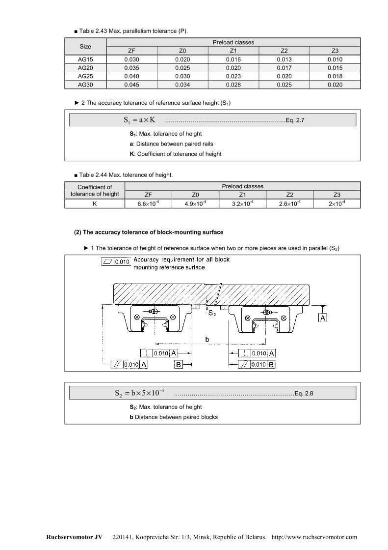
Ruchservomotor JV 220141, Kooprevicha Str. 1/3, Minsk, Republic of Belarus. http://www.ruchservomotor.com
■ Table 2.43 Max. parallelism tolerance (P).
Preload classesSize
ZF Z0 Z1 Z2 Z3AG15 0.030 0.020 0.016 0.013 0.010AG20 0.035 0.025 0.020 0.017 0.015AG25 0.040 0.030 0.023 0.020 0.018AG30 0.045 0.034 0.028 0.025 0.020
► 2 The accuracy tolerance of reference surface height (S1)
KaS1 ×= ……………………………………………..………Eq. 2.7
S1: Max. tolerance of height
a: Distance between paired rails
K: Coefficient of tolerance of height
■ Table 2.44 Max. tolerance of height.
Preload classesCoefficient oftolerance of height ZF Z0 Z1 Z2 Z3
K 6.6×10⁻⁴ 4.9×10⁻⁴ 3.2×10⁻⁴ 2.6×10⁻⁴ 2×10⁻⁴
(2) The accuracy tolerance of block-mounting surface
► 1 The tolerance of height of reference surface when two or more pieces are used in parallel (S2)
52 105bS −××= ……………………………………………..………Eq. 2.8
S2: Max. tolerance of height
b Distance between paired blocks
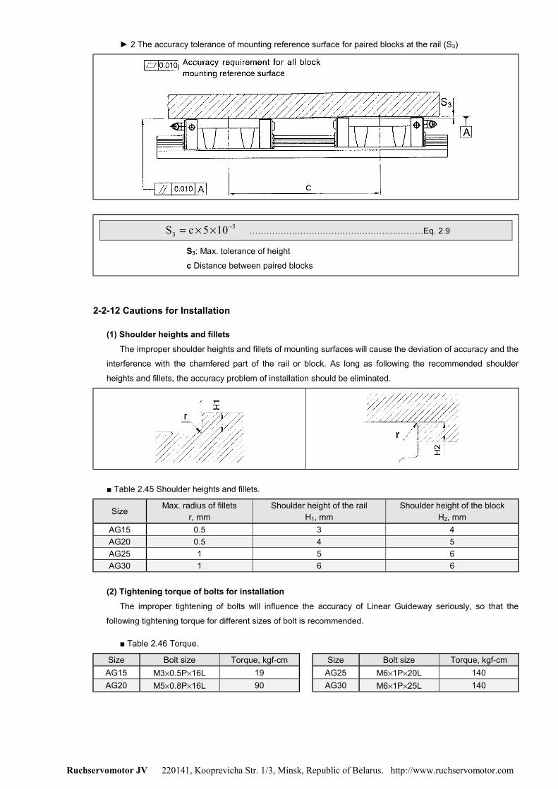
Ruchservomotor JV 220141, Kooprevicha Str. 1/3, Minsk, Republic of Belarus. http://www.ruchservomotor.com
► 2 The accuracy tolerance of mounting reference surface for paired blocks at the rail (S3)
53 105cS −××= ……………………………………………..………Eq. 2.9
S3: Max. tolerance of height
c Distance between paired blocks
2-2-12 Cautions for Installation
(1) Shoulder heights and filletsThe improper shoulder heights and fillets of mounting surfaces will cause the deviation of accuracy and the
interference with the chamfered part of the rail or block. As long as following the recommended shoulder
heights and fillets, the accuracy problem of installation should be eliminated.
■ Table 2.45 Shoulder heights and fillets.
Size Max. radius of filletsr, mm
Shoulder height of the railH1, mm
Shoulder height of the blockH2, mm
AG15 0.5 3 4AG20 0.5 4 5AG25 1 5 6AG30 1 6 6
(2) Tightening torque of bolts for installationThe improper tightening of bolts will influence the accuracy of Linear Guideway seriously, so that the
following tightening torque for different sizes of bolt is recommended.
■ Table 2.46 Torque.
Size Bolt size Torque, kgf-cm Size Bolt size Torque, kgf-cmAG15 M3×0.5P×16L 19 AG25 M6×1P×20L 140AG20 M5×0.8P×16L 90 AG30 M6×1P×25L 140
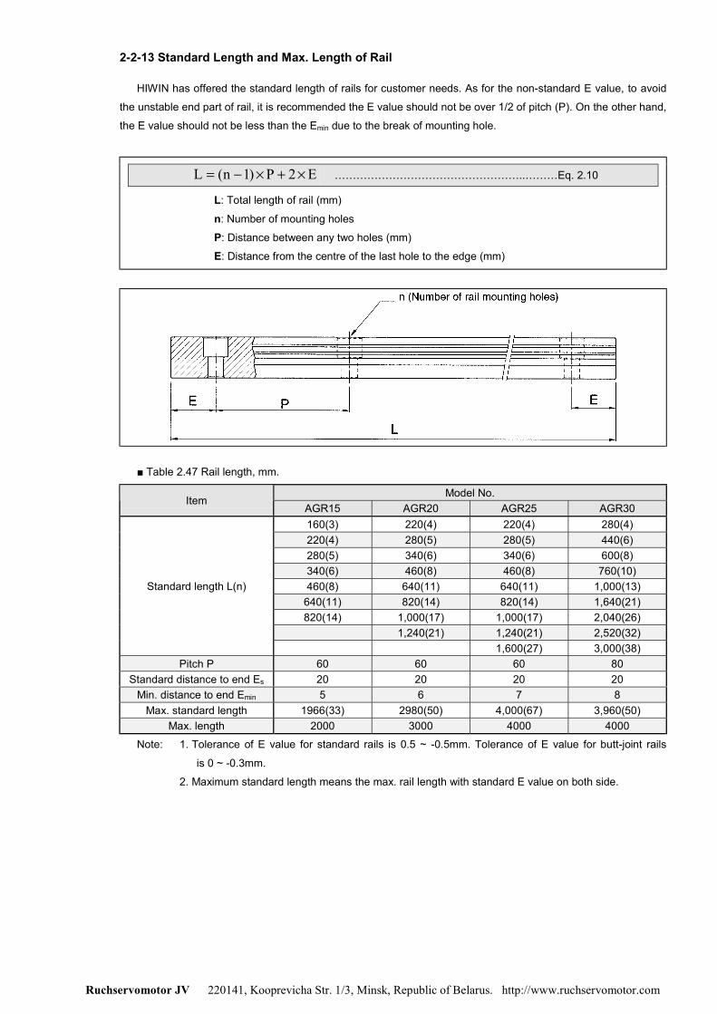
Ruchservomotor JV 220141, Kooprevicha Str. 1/3, Minsk, Republic of Belarus. http://www.ruchservomotor.com
2-2-13 Standard Length and Max. Length of Rail
HIWIN has offered the standard length of rails for customer needs. As for the non-standard E value, to avoid
the unstable end part of rail, it is recommended the E value should not be over 1/2 of pitch (P). On the other hand,
the E value should not be less than the Emin due to the break of mounting hole.
E2P)1n(L ×+×−= ……………………………………………..………Eq. 2.10
L: Total length of rail (mm)
n: Number of mounting holes
P: Distance between any two holes (mm)
E: Distance from the centre of the last hole to the edge (mm)
■ Table 2.47 Rail length, mm.
Model No.Item
AGR15 AGR20 AGR25 AGR30160(3) 220(4) 220(4) 280(4)220(4) 280(5) 280(5) 440(6)280(5) 340(6) 340(6) 600(8)340(6) 460(8) 460(8) 760(10)460(8) 640(11) 640(11) 1,000(13)
640(11) 820(14) 820(14) 1,640(21)820(14) 1,000(17) 1,000(17) 2,040(26)
1,240(21) 1,240(21) 2,520(32)
Standard length L(n)
1,600(27) 3,000(38)Pitch P 60 60 60 80
Standard distance to end Es 20 20 20 20Min. distance to end Emin 5 6 7 8
Max. standard length 1966(33) 2980(50) 4,000(67) 3,960(50)Max. length 2000 3000 4000 4000
Note: 1. Tolerance of E value for standard rails is 0.5 ~ -0.5mm. Tolerance of E value for butt-joint rails
is 0 ~ -0.3mm.
2. Maximum standard length means the max. rail length with standard E value on both side.

Ruchservomotor JV 220141, Kooprevicha Str. 1/3, Minsk, Republic of Belarus. http://www.ruchservomotor.com
2-2-14 Dimensions for HIWIN AG Series (1) AGH-SA /AGH-CA
WeightDimensions ofAssembly
(mm)
Dimensions of Block(mm)
Dimensions of Rail(mm)
MountingBolt
for Rail(mm)
BasicDynamic
LoadRating(kgf)
BasicStaticLoad
Rating(kgf)
Static RatedMoment(kgf-m) Block
(kg)Rail
(kg/m)Model No.
H H1 N W B B1 C L1 L G M×ℓ T H2 Wr Hr D h d P E C C0 M0 Mx My
AGH15-SA - 22.8 41 440 590 4.8 2.3 2.3 0.12AGH15-CA
24 5 9.5 34 26 426 38.7 56.9
5.7 M4×X7 6 5.5 15 13.5 6 4.5 3.5 60 20 M3×16640 1010 8.3 6.3 6.3 0.17
1.43
AGH20-SA - 26.2 48 650 920 10.1 4.5 4.5 0.2AGH20-CA
28 6 11 42 32 532 44.1 65.9
12 M5×8 7.5 6 20 15.5 9.5 8.5 6 60 20 M5×16 970 1450 15.9 10.4 10.4 0.292.16
AGH25-SA - 34.5 58.7 1080 1330 16.7 7.8 7.8 0.34AGH25-CA
33 7 12.5 48 35 6.535 58.3 82.5
12 M6×9 8 7 23 18.5 11 9 7 60 20 M6×201550 2290 28.7 21.1 21.1 0.51
2.95
AGH30-SA - 36.6 66.4 1550 2030 30.8 14.0 14.0 0.57AGH30-CA
42 10 16 60 40 1040 65.2 95
12 M8×12 9 8 28 24 11 9 7 80 20 M6×252470 3390 51.3 35.5 35.5 0.88
4.76
Note: Above listed dimensions of rail are dimensions of AGR-R (bolt hole, mounting from above). Dimensions of AGR-U (large bolt hole, mounting from above) and AGR-T (tapped hole,
mounting from below) refer to page 53.

Ruchservomotor JV 220141, Kooprevicha Str. 1/3, Minsk, Republic of Belarus. http://www.ruchservomotor.com
(2) AGW-SA / AGW-CA
WeightDimensions ofAssembly
(mm)
Dimensions of Block(mm)
Dimensions of Rail(mm)
MountingBolt
for Rail(mm)
BasicDynamic
LoadRating(kgf)
BasicStaticLoad
Rating(kgf)
Static RatedMoment(kgf-m) Block
(kg)Rail
(kg/m)Model No.
H H1 N W B B1 C L1 L G M T H2 Wr Hr D h d P E C C0 M0 Mx My
AGW15-SA - 22.8 41 440 590 4.8 2.3 2.3 0.15AGW15-CA
24 5 18.5 52 41 5.526 38.7 56.9
5.7 M5 7 5.5 15 13.5 6 4.5 3.5 60 20 M3×16640 1010 8.3 6.3 6.3 0.23
1.43
AGW20-SA - 26.2 48 650 920 10.1 4.5 4.5 0.24AGW20-CA
28 6 19.5 59 49 532 44.1 65.9
12 M6 9 6 20 15.5 9.5 8.5 6 60 20 M5×16 970 1450 15.9 10.4 10.4 0.362.16
AGW25-SA - 34.5 58.7 1080 1330 16.7 7.8 7.8 0.44AGW25-CA
33 7 25 73 60 6.535 58.3 82.5
12 M8 10 7 23 18.5 11 9 7 60 20 M6×20 1550 2290 28.7 21.1 21.1 0.682.95
AGW30-SA - 36.6 66.4 1550 2030 30.8 14.0 14.0 0.72AGW30-CA
42 10 31 90 72 940 65.2 95
12 M10 10 8 28 24 11 9 7 80 20 M6×25 2470 3390 51.3 35.5 35.5 1.164.76
Note: Above listed dimensions of rail are dimensions of AGR-R (bolt hole, mounting from above). Dimensions of AGR-U (large bolt hole, mounting from above) and AGR-T (tapped hole,
mounting from below) refer to page 53.
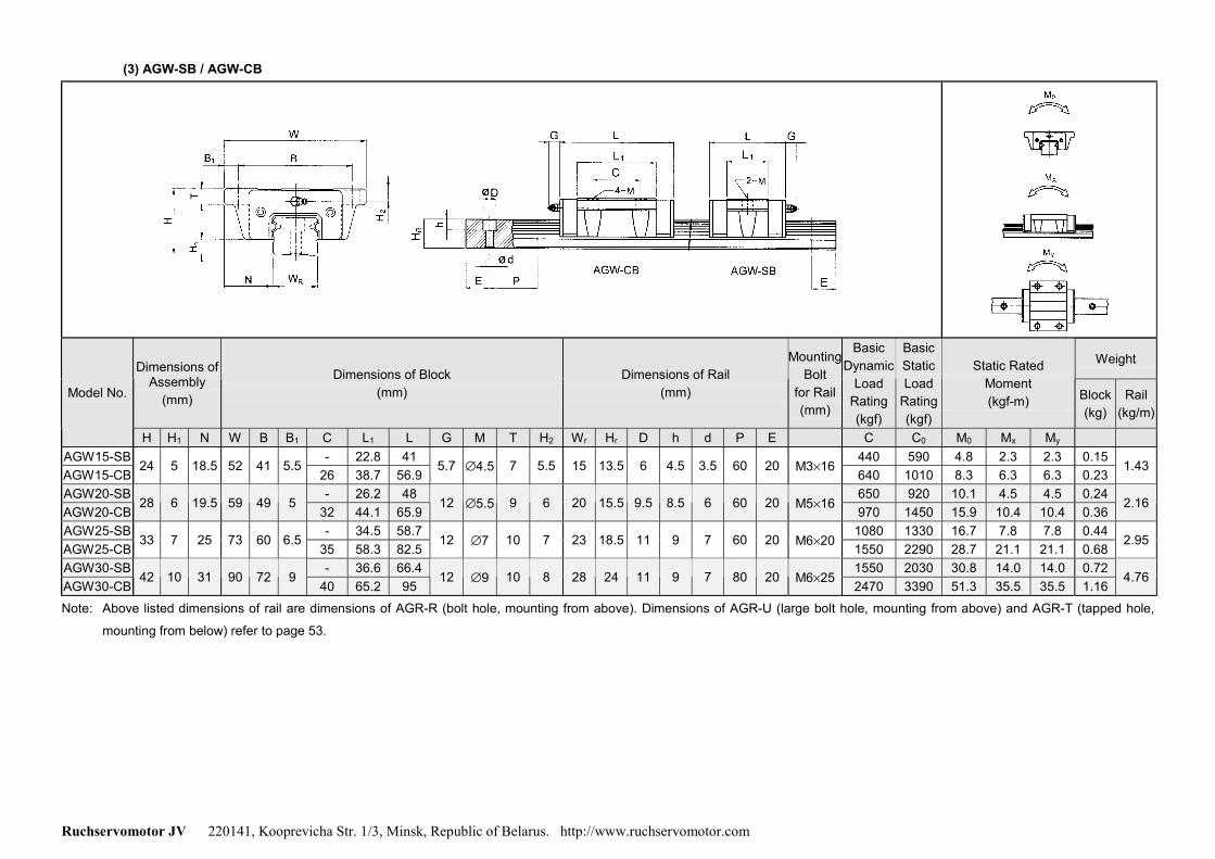
Ruchservomotor JV 220141, Kooprevicha Str. 1/3, Minsk, Republic of Belarus. http://www.ruchservomotor.com
(3) AGW-SB / AGW-CB
WeightDimensions ofAssembly
(mm)
Dimensions of Block(mm)
Dimensions of Rail(mm)
MountingBolt
for Rail(mm)
BasicDynamic
LoadRating(kgf)
BasicStaticLoad
Rating(kgf)
Static RatedMoment(kgf-m) Block
(kg)Rail
(kg/m)Model No.
H H1 N W B B1 C L1 L G M T H2 Wr Hr D h d P E C C0 M0 Mx My
AGW15-SB - 22.8 41 440 590 4.8 2.3 2.3 0.15AGW15-CB
24 5 18.5 52 41 5.526 38.7 56.9
5.7 ∅4.5 7 5.5 15 13.5 6 4.5 3.5 60 20 M3×16640 1010 8.3 6.3 6.3 0.23
1.43
AGW20-SB - 26.2 48 650 920 10.1 4.5 4.5 0.24AGW20-CB
28 6 19.5 59 49 532 44.1 65.9
12 ∅5.5 9 6 20 15.5 9.5 8.5 6 60 20 M5×16 970 1450 15.9 10.4 10.4 0.362.16
AGW25-SB - 34.5 58.7 1080 1330 16.7 7.8 7.8 0.44AGW25-CB
33 7 25 73 60 6.535 58.3 82.5
12 ∅7 10 7 23 18.5 11 9 7 60 20 M6×20 1550 2290 28.7 21.1 21.1 0.682.95
AGW30-SB - 36.6 66.4 1550 2030 30.8 14.0 14.0 0.72AGW30-CB
42 10 31 90 72 940 65.2 95
12 ∅9 10 8 28 24 11 9 7 80 20 M6×25 2470 3390 51.3 35.5 35.5 1.164.76
Note: Above listed dimensions of rail are dimensions of AGR-R (bolt hole, mounting from above). Dimensions of AGR-U (large bolt hole, mounting from above) and AGR-T (tapped hole,
mounting from below) refer to page 53.

Ruchservomotor JV 220141, Kooprevicha Str. 1/3, Minsk, Republic of Belarus. http://www.ruchservomotor.com
(4) Dimensions for AGR-T (Rail mounting from below)
Dimensions of rail, (mm)Model No.
WR HR S h P EWeight(kg/m)
AGR15-T 15 13.5 M5×0.8P 7 60 20 1.44AGR20-T 20 15.5 M6×1P 9 60 20 2.23AGR25-T 23 18.5 M6×1P 10 60 20 3.06AGR30-T 28 24 M8×1.25P 14 80 20 4.83
(5) Dimensions for AGR-U (Large mounting hole)
Dimensions of rail, (mm)Model No. Mounting bolt
for rail, (mm) WR HR S h d P EWeight(kg/m)
AGR15-U M4×16 15 13.5 7.5 5.3 4.5 60 20 1.41AGR30-U M8×25 28 24 14 12 9 80 20 4.65
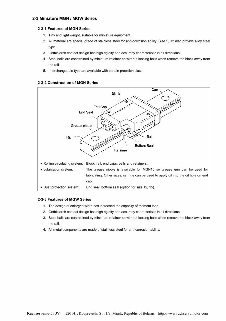
Ruchservomotor JV 220141, Kooprevicha Str. 1/3, Minsk, Republic of Belarus. http://www.ruchservomotor.com
2-3 Miniature MGN / MGW Series
2-3-1 Features of MGN Series1. Tiny and light weight, suitable for miniature equipment.
2. All material are special grade of stainless steel for anti-corrosion ability. Size 9, 12 also provide alloy steel
type.
3. Gothic arch contact design has high rigidity and accuracy characteristic in all directions.
4. Steel balls are constrained by miniature retainer so without loosing balls when remove the block away from
the rail.
5. Interchangeable type are available with certain precision class.
2-3-2 Construction of MGN Series
● Rolling circulating system: Block, rail, end caps, balls and retainers.
● Lubrication system: The grease nipple is available for MGN15 so grease gun can be used for
lubricating. Other sizes, syringe can be used to apply oil into the oil hole on end
cap.
● Dust protection system: End seal, bottom seal (option for size 12, 15).
2-3-3 Features of MGW Series1. The design of enlarged width has increased the capacity of moment load.
2. Gothic arch contact design has high rigidity and accuracy characteristic in all directions.
3. Steel balls are constrained by miniature retainer so without loosing balls when remove the block away from
the rail.
4. All metal components are made of stainless steel for anti-corrosion ability.
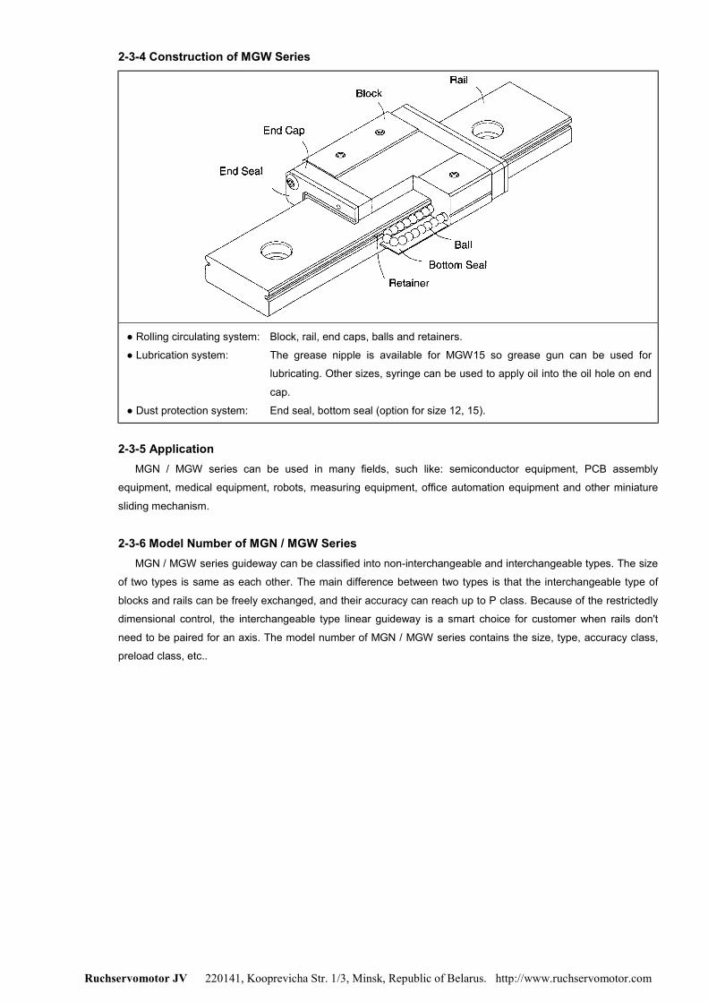
Ruchservomotor JV 220141, Kooprevicha Str. 1/3, Minsk, Republic of Belarus. http://www.ruchservomotor.com
2-3-4 Construction of MGW Series
● Rolling circulating system: Block, rail, end caps, balls and retainers.
● Lubrication system: The grease nipple is available for MGW15 so grease gun can be used for
lubricating. Other sizes, syringe can be used to apply oil into the oil hole on end
cap.
● Dust protection system: End seal, bottom seal (option for size 12, 15).
2-3-5 ApplicationMGN / MGW series can be used in many fields, such like: semiconductor equipment, PCB assembly
equipment, medical equipment, robots, measuring equipment, office automation equipment and other miniature
sliding mechanism.
2-3-6 Model Number of MGN / MGW SeriesMGN / MGW series guideway can be classified into non-interchangeable and interchangeable types. The size
of two types is same as each other. The main difference between two types is that the interchangeable type of
blocks and rails can be freely exchanged, and their accuracy can reach up to P class. Because of the restrictedly
dimensional control, the interchangeable type linear guideway is a smart choice for customer when rails don't
need to be paired for an axis. The model number of MGN / MGW series contains the size, type, accuracy class,
preload class, etc..

Ruchservomotor JV 220141, Kooprevicha Str. 1/3, Minsk, Republic of Belarus. http://www.ruchservomotor.com
(1) Non-interchangeable type
MGW 12 C E 2 R1600 E Z1 P M II + U● MGN / MGW series
● Model size7, 9, 12, 15
● Block typeC: Standard; H: Long
● Block special option
● No. of blocks per rail
● Rail length (mm)
● Bottom seal option3
● No. of rails per axis2
● Type of steel:M: Stainless steelNo code: Alloy steel1
● Precision code: C, H, P
● Preload code: ZF, Z0, Z1
● Rail special option
Note: 1. MGN series are made of stainless steel, but size 9, 12 also provide the alloy steel. MGW series aremade of stainless steel.
2. The Roman numerals used to express the number of rails used in one axis. As for the single rail inan axis, it shows no symbol.
3. Size of MGN / MGW 12, 15 provide the bottom seal.
(2) Interchangeable type● Interchangeable block
MGN 12 C E Z1 P M + U● MGN series
● Model size7, 9, 12, 15
● Block typeC: Standard; H: Long
● Block special option
● Bottom seal option
● Type of steel:M: Stainless steelNo code: Alloy steel
● Precision code: C, H, P
● Preload code: ZF, Z0, Z1
● Interchangeable rail
MGN R 12 R1600 E P M● MGN series
● Interchangeable rail
● Model size7, 9, 12, 15
● Rail length (mm)
● Type of steel:M: Stainless steelNo code: Alloy steel
● Precision code: C, H, P
● Rail special option
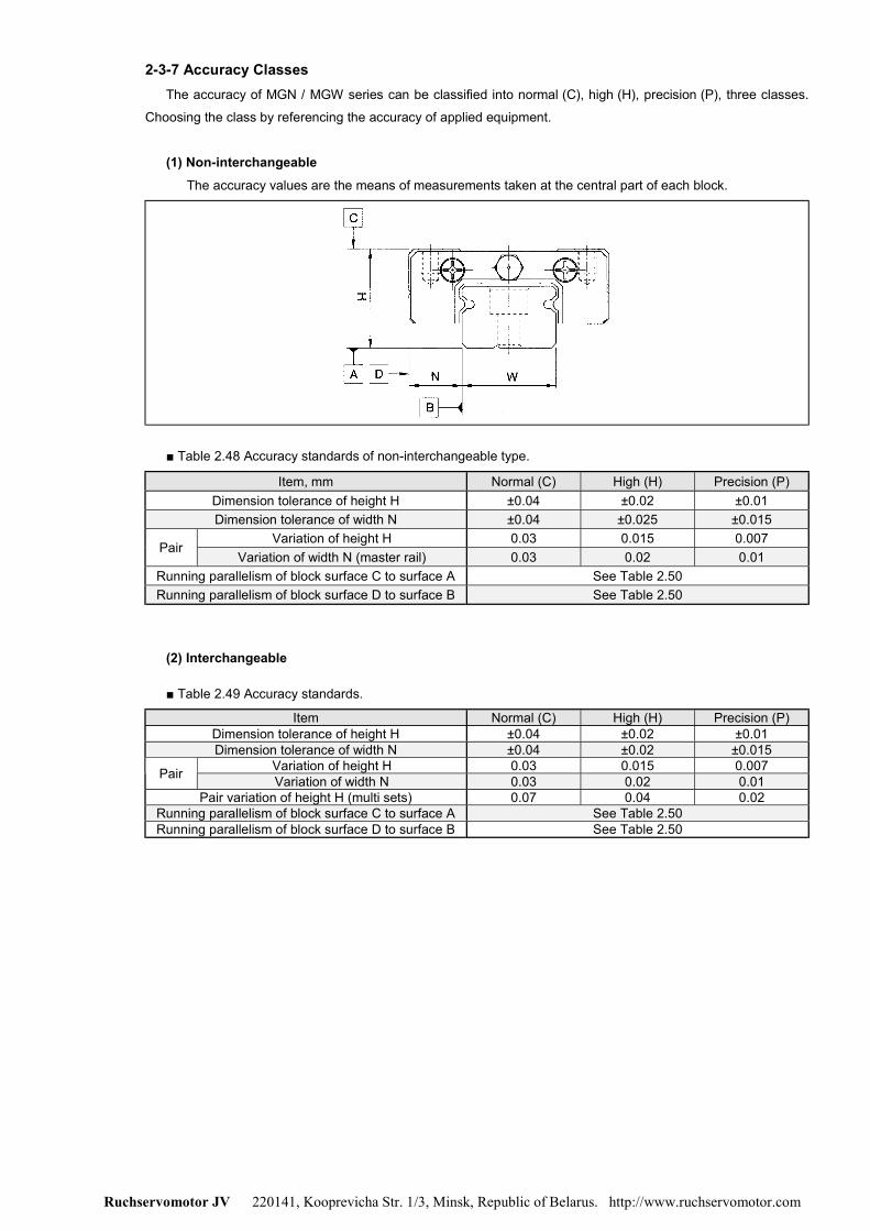
Ruchservomotor JV 220141, Kooprevicha Str. 1/3, Minsk, Republic of Belarus. http://www.ruchservomotor.com
2-3-7 Accuracy ClassesThe accuracy of MGN / MGW series can be classified into normal (C), high (H), precision (P), three classes.
Choosing the class by referencing the accuracy of applied equipment.
(1) Non-interchangeableThe accuracy values are the means of measurements taken at the central part of each block.
■ Table 2.48 Accuracy standards of non-interchangeable type.
Item, mm Normal (C) High (H) Precision (P)Dimension tolerance of height H ±0.04 ±0.02 ±0.01Dimension tolerance of width N ±0.04 ±0.025 ±0.015
Variation of height H 0.03 0.015 0.007Pair
Variation of width N (master rail) 0.03 0.02 0.01Running parallelism of block surface C to surface A See Table 2.50Running parallelism of block surface D to surface B See Table 2.50
(2) Interchangeable
■ Table 2.49 Accuracy standards.
Item Normal (C) High (H) Precision (P)Dimension tolerance of height H ±0.04 ±0.02 ±0.01Dimension tolerance of width N ±0.04 ±0.02 ±0.015
Variation of height H 0.03 0.015 0.007Pair Variation of width N 0.03 0.02 0.01Pair variation of height H (multi sets) 0.07 0.04 0.02
Running parallelism of block surface C to surface A See Table 2.50Running parallelism of block surface D to surface B See Table 2.50
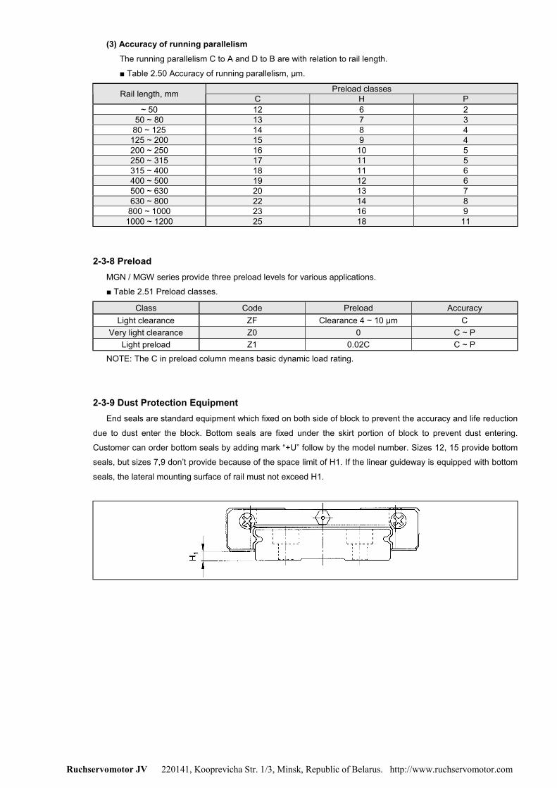
Ruchservomotor JV 220141, Kooprevicha Str. 1/3, Minsk, Republic of Belarus. http://www.ruchservomotor.com
(3) Accuracy of running parallelismThe running parallelism C to A and D to B are with relation to rail length.
■ Table 2.50 Accuracy of running parallelism, µm.
Preload classesRail length, mm C H P~ 50 12 6 2
50 ~ 80 13 7 380 ~ 125 14 8 4
125 ~ 200 15 9 4200 ~ 250 16 10 5250 ~ 315 17 11 5315 ~ 400 18 11 6400 ~ 500 19 12 6500 ~ 630 20 13 7630 ~ 800 22 14 8800 ~ 1000 23 16 9
1000 ~ 1200 25 18 11
2-3-8 PreloadMGN / MGW series provide three preload levels for various applications.
■ Table 2.51 Preload classes.
Class Code Preload AccuracyLight clearance ZF Clearance 4 ~ 10 µm C
Very light clearance Z0 0 C ~ PLight preload Z1 0.02C C ~ P
NOTE: The C in preload column means basic dynamic load rating.
2-3-9 Dust Protection EquipmentEnd seals are standard equipment which fixed on both side of block to prevent the accuracy and life reduction
due to dust enter the block. Bottom seals are fixed under the skirt portion of block to prevent dust entering.
Customer can order bottom seals by adding mark “+U” follow by the model number. Sizes 12, 15 provide bottom
seals, but sizes 7,9 don’t provide because of the space limit of H1. If the linear guideway is equipped with bottom
seals, the lateral mounting surface of rail must not exceed H1.
Ruchservomotor JV 220141, Kooprevicha Str. 1/3, Minsk, Republic of Belarus. http://www.ruchservomotor.com
■ Table 2.51
Size Bottom seal H1, mmMGN7 - -MGN7 - -
MGN12 + 2MGN15 + 3MGW7 - -MGW9 - -MGW12 + 3.6MGW15 + 3.6
2-3-10 Shoulder Heights and Fillets
■ Table 2.53 Shoulder heights and fillets.
Max. radius of fillets Shoulder heightsSize
R1, mm R2, mm H1, mm H2, mmMGN7 0.2 0.2 1.2 3MGN9 0.2 0.3 1.7 3
MGN12 0.3 0.4 1.7 4MGN15 0.5 0.5 2.5 5MGW7 0.2 0.2 1.7 3MGW9 0.3 0.3 2.5 3
MGW12 0.4 0.4 3 4MGW15 0.4 0.8 3 5
2-3-11 Standard Length and Max. Length of RailHIWIN has offered the standard length of rails for customer needs. As for the non-standard E value, to avoid
the unstable end part of rail, it is recommended the E value should not be over 1/2 of pitch (P). On the other hand,
the E value should not be less than the Emin due to the break of mounting hole.
E2P)1n(L ×+×−= ……………………..………Eq. 2.11
L: Total length of rail (mm)
n: Number of mounting holes
P: Distance between any two holes (mm)
E: Distance from the centre of the last hole to the edge (mm)
Ruchservomotor JV 220141, Kooprevicha Str. 1/3, Minsk, Republic of Belarus. http://www.ruchservomotor.com
■ Table 2.54 Rail length, mm.
Model No.Item MGNR
7MMGNR
9MMGNR
9MGNR
12MMGNR
12MGNR15M
MGWR7M
MGWR9M
MGWR12M
MGWR15M
40 (3) 55 (3) 70 (3) 70 (2) 80 (3) 80 (3) 110 (3) 110 (3)55 (4) 75 (4) 95 (4) 110 (3) 110 (4) 110 (4) 150 (4) 150 (4)70 (5) 95 (5) 120 (5) 150 (4) 140 (5) 140 (5) 190 (5) 190 (5)85 (6) 115 (6) 145 (6) 190 (5) 170 (6) 170 (6) 230 (6) 230 (6)
100 (7) 135 (7) 170 (7) 230 (6) 200 (7) 200 (7) 270 (7) 270 (7)130 (9) 155 (8) 195 (8) 270 (7) 260 (9) 230 (8) 310 (8) 310 (8)
175 (9) 220 (9) 310 (8) 260 (9) 350 (9) 350 (9)275 (14) 245 (10) 350 (9) 290 (10) 390 (10) 390 (10)375 (19) 270 (11) 390 (10) 350 (14) 430 (11) 430 (11)
320 (13) 430 (11) 500 19() 510 (13) 510 (13)370 (15) 470 (12) 590 (15) 590 (15)470 (19) 550 (14) 750 (19) 750 (19)570 (23) 670 (17) 910 (23) 910 (23)
Standard lengthL(n)
870 (22)Pitch P 15 20 25 40 30 30 40 40
Standard distanceto end Es
5 7.5 10 15 10 10 15 15
Min. distance toend Emin
3 4 4 4 4 4 4 4
Max. standardlength 295 595 995 995 1195 990 590 990 990 990
Max. length 300 600 1000 1000 1200 1000 600 1000 1000 1000
Note: 1. Tolerance of E value for standard rails is 0.5 ~ -0.5mm. Tolerance of E value for butt-joint rails
is 0 ~ -0.3mm.
2. Maximum standard length means the max. rail length with standard E value on both side.
3. The specification with “M” mark are stainless steel and without “M” mark are alloy steel.

Ruchservomotor JV 220141, Kooprevicha Str. 1/3, Minsk, Republic of Belarus. http://www.ruchservomotor.com
2-3-12 Dimensions for HIWIN MGN / MGW Series
(1) MGN-C / MGN-H
WeightDimensions ofAssembly
(mm)
Dimensions of Block(mm)
Dimensions of Rail(mm)
MountingBolt
for Rail(mm)
BasicDynamic
LoadRating(kgf)
BasicStaticLoad
Rating(kgf)
Static RatedMoment(kgf-m) Block
(g)Rail
(kg/m)Model No.
H H1 N W B B1 C L1 L G M×ℓ Gn H2 Wr Hr D h d P E C C0 M0 Mx My
MGN7-C 8 13.5 22.5 100 127 0.48 0.29 0.29 10MGN7-H
8 1.5 5 17 12 2.513 21.8 30.8
- M2×2.5 Ø0.8 1.5 7 4.8 4.2 2.3 2.4 15 5 M2×6140 200 0.78 0.49 0.49 15
0.22
MGN9-C 10 18.9 28.9 190 260 1.2 0.75 0.75 16MGN9-H
10 2 5.5 20 15 2.516 29.9 39.9
- M3×3 Ø0.8 1.8 9 6.5 6 3.5 3.5 20 7.5 M3×8260 410 2 1.9 1.9 26
0.38
MGN12-C 15 21.7 34.7 290 400 2.6 1.4 1.4 34MGN12-H
13 3 7.5 27 20 3.520 32.4 45.4
- M3×3.5 Ø0.8 2.5 12 8 6 4.5 3.5 25 10 M3×8380 600 3.9 3.7 3.7 54
0.65
MGN15-C 20 26.7 42.1 470 570 4.6 2.2 2.2 59MGN15-H
16 4 8.5 32 25 3.525 43.4 58.8
4.5 M3×4 + 3 15 10 6 4.5 3.5 40 15 M3×10650 930 7.5 5.9 5.9 92
1.06
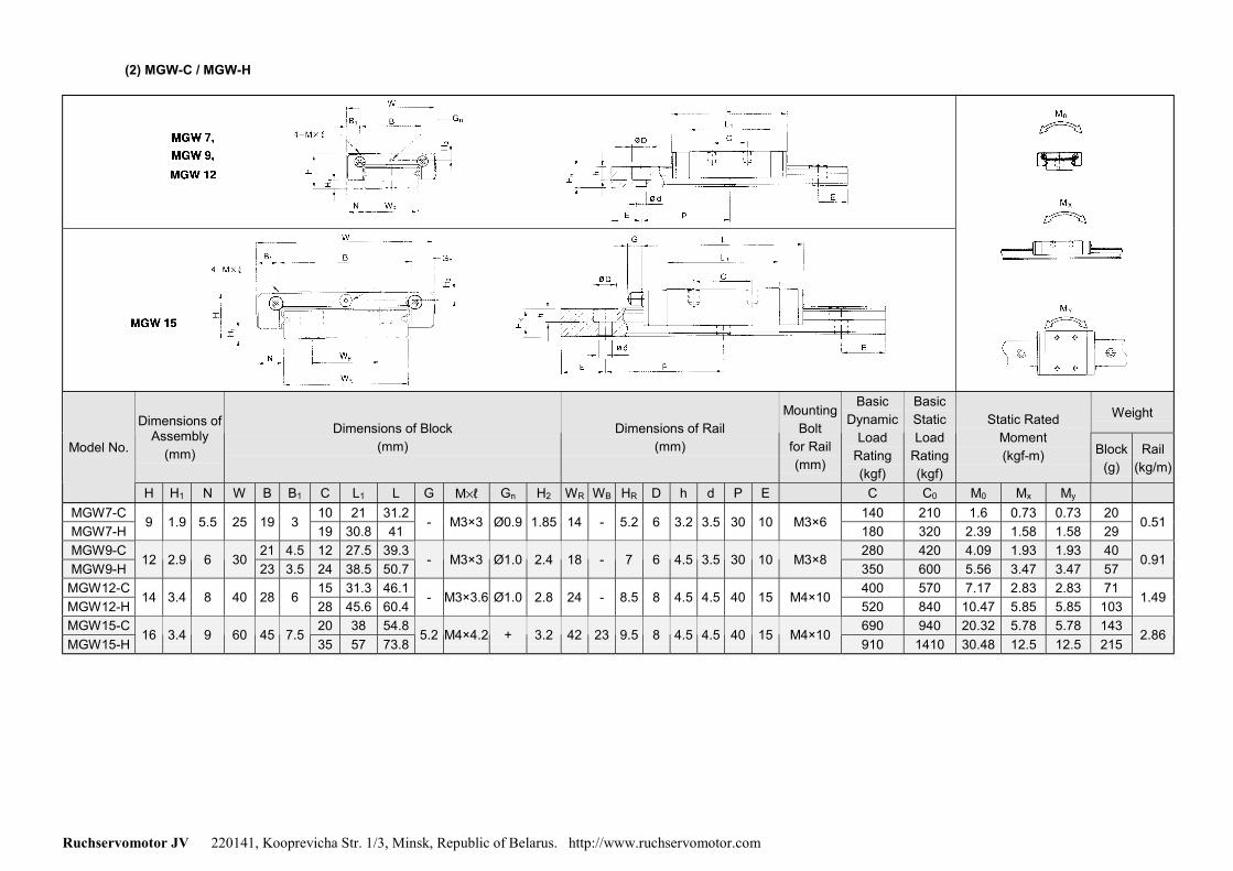
Ruchservomotor JV 220141, Kooprevicha Str. 1/3, Minsk, Republic of Belarus. http://www.ruchservomotor.com
(2) MGW-C / MGW-H
WeightDimensions ofAssembly
(mm)
Dimensions of Block(mm)
Dimensions of Rail(mm)
MountingBolt
for Rail(mm)
BasicDynamic
LoadRating(kgf)
BasicStaticLoad
Rating(kgf)
Static RatedMoment(kgf-m) Block
(g)Rail
(kg/m)Model No.
H H1 N W B B1 C L1 L G M×ℓ Gn H2 WR WB HR D h d P E C C0 M0 Mx My
MGW7-C 10 21 31.2 140 210 1.6 0.73 0.73 20MGW7-H
9 1.9 5.5 25 19 319 30.8 41
- M3×3 Ø0.9 1.85 14 - 5.2 6 3.2 3.5 30 10 M3×6180 320 2.39 1.58 1.58 29
0.51
MGW9-C 21 4.5 12 27.5 39.3 280 420 4.09 1.93 1.93 40MGW9-H
12 2.9 6 3023 3.5 24 38.5 50.7
- M3×3 Ø1.0 2.4 18 - 7 6 4.5 3.5 30 10 M3×8350 600 5.56 3.47 3.47 57
0.91
MGW12-C 15 31.3 46.1 400 570 7.17 2.83 2.83 71MGW12-H
14 3.4 8 40 28 628 45.6 60.4
- M3×3.6 Ø1.0 2.8 24 - 8.5 8 4.5 4.5 40 15 M4×10520 840 10.47 5.85 5.85 103
1.49
MGW15-C 20 38 54.8 690 940 20.32 5.78 5.78 143MGW15-H
16 3.4 9 60 45 7.535 57 73.8
5.2 M4×4.2 + 3.2 42 23 9.5 8 4.5 4.5 40 15 M4×10910 1410 30.48 12.5 12.5 215
2.86
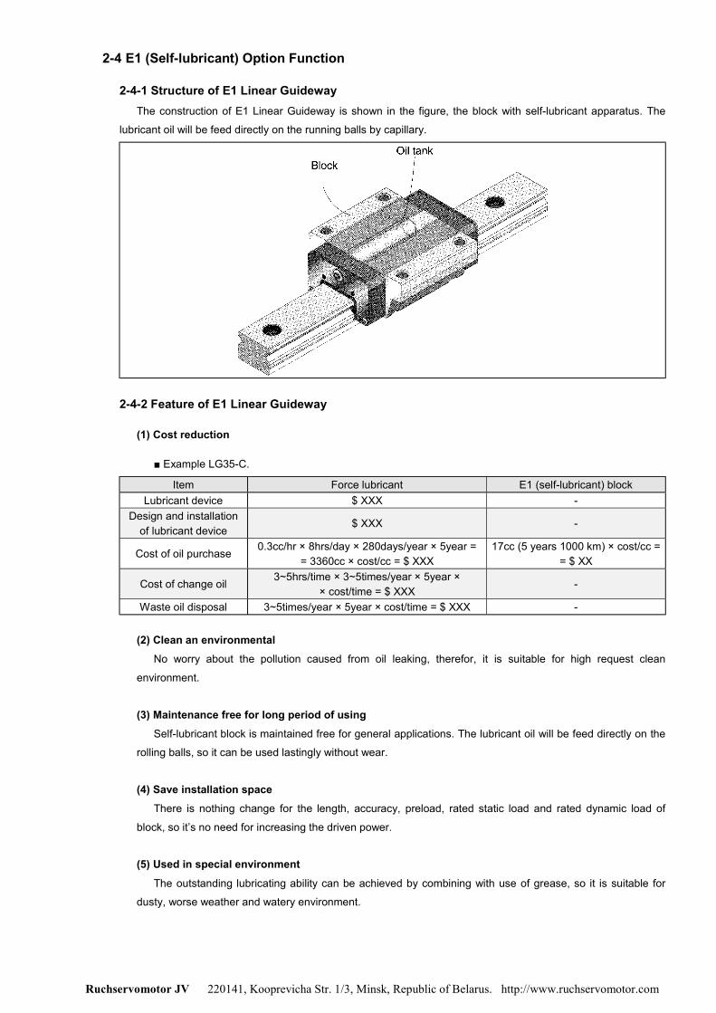
Ruchservomotor JV 220141, Kooprevicha Str. 1/3, Minsk, Republic of Belarus. http://www.ruchservomotor.com
2-4 E1 (Self-lubricant) Option Function
2-4-1 Structure of E1 Linear GuidewayThe construction of E1 Linear Guideway is shown in the figure, the block with self-lubricant apparatus. The
lubricant oil will be feed directly on the running balls by capillary.
2-4-2 Feature of E1 Linear Guideway
(1) Cost reduction
■ Example LG35-C.
Item Force lubricant E1 (self-lubricant) blockLubricant device $ XXX -
Design and installationof lubricant device
$ XXX -
Cost of oil purchase 0.3cc/hr × 8hrs/day × 280days/year × 5year == 3360cc × cost/cc = $ XXX
17cc (5 years 1000 km) × cost/cc == $ XX
Cost of change oil 3~5hrs/time × 3~5times/year × 5year ×× cost/time = $ XXX
-
Waste oil disposal 3~5times/year × 5year × cost/time = $ XXX -
(2) Clean an environmentalNo worry about the pollution caused from oil leaking, therefor, it is suitable for high request clean
environment.
(3) Maintenance free for long period of usingSelf-lubricant block is maintained free for general applications. The lubricant oil will be feed directly on the
rolling balls, so it can be used lastingly without wear.
(4) Save installation spaceThere is nothing change for the length, accuracy, preload, rated static load and rated dynamic load of
block, so it’s no need for increasing the driven power.
(5) Used in special environmentThe outstanding lubricating ability can be achieved by combining with use of grease, so it is suitable for
dusty, worse weather and watery environment.

Ruchservomotor JV 220141, Kooprevicha Str. 1/3, Minsk, Republic of Belarus. http://www.ruchservomotor.com
2-4-3 Application
• Machine tool
• Manufacture machine: Plastic injection, printing, paper making, textile machine, food processing machine,
wood working machine, etc..
• Electronic machine: semiconductor equipment, robot, X-Y table, measuring and inspecting equipment.
• Others: Medical equipment, transporting device, housing equipment.
2-4-4 Specification
Add “/E1” after the specification of Linear Guideway:
Example: LGW25-CC-2R-1600-Z1-P-II + ZZ / E1
AGW30-CA-2R-1600-Z1-P-II + ZZ / E1
■ Applicable specification.
Square type Flange typeSeries Load type
Tap hole Tap hole Drilled hole CombinationHeavy load LGH-CA - - LGW-CC
LGSuper heavy load LGH-HA - - LGW-HC
Medium load AGH-SA AGW-SA - -AG
Heavy load AGH-CA AGW-CA - -
2-4-5 Lubrication capability of E1 Linear Guideway
Life testing with light preload:
Test conditions Characteristic of lubricant oil
Model No.: LGW35-CC.Speed: 80 m/min.Stroke: 1500 mm.Load: 500 kgf.
Synthetic base oil with stable characteristic.Range of oil operation temperature -15 ~ 240°C, include the most conditionof linear guideway.Reduce friction and anti-abrasion.Against corrosion and rust.Non-toxic.
Note: The test was carried out without combining the use of grease.
2-4-6 InstallationBe careful when using in vertical axes, the arrow mark on block must toward the ground. If inverse the block
direction then theself-lubricant function can not work and damage will occur soon.
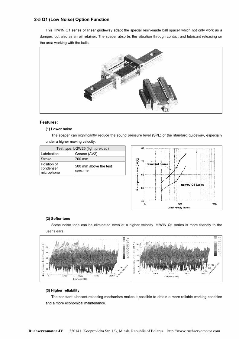
Ruchservomotor JV 220141, Kooprevicha Str. 1/3, Minsk, Republic of Belarus. http://www.ruchservomotor.com
2-5 Q1 (Low Noise) Option Function
This HIWIN Q1 series of linear guideway adapt the special resin-made ball spacer which not only work as a
damper, but also as an oil retainer. The spacer absorbs the vibration through contact and lubricant releasing on
the area working with the balls.
Features:(1) Lower noise
The spacer can significantly reduce the sound pressure level (SPL) of the standard guideway, especially
under a higher moving velocity.
Test type: LGW25 (light preload)Lubrication Grease (AV2)Stroke 700 mmPosition ofcondensermicrophone
500 mm above the testspecimen
(2) Softer toneSome noise tone can be eliminated even at a higher velocity. HIWIN Q1 series is more friendly to the
user’s ears.
(3) Higher reliabilityThe constant lubricant-releasing mechanism makes it possible to obtain a more reliable working condition
and a more economical maintenance.

Ruchservomotor JV 220141, Kooprevicha Str. 1/3, Minsk, Republic of Belarus. http://www.ruchservomotor.com
2-6 SE (Heat Resistant) Option Function
Linear guideway with heat resistance steel end caps and copper bolt caps.
(1) FeatureWell temperature resistant ability. Service temperature under 150°C, and resistance temperature can up
to 200°C.
(2) ApplicationHeat treatment equipment, welding machine, glass manufacturing equipment and vacuum using equipment
(without vapour dispersion from plastic or rubber at high temperature).
(3) Applicable series
Series SizeLG 15, 20, 25, 30, 35, 45, 55AG 15, 20, 25, 30
MGN 9, 12, 15
(4) SpecificationAdd the mark “/SE” after the specification number for steel end caps and copper bolt caps.
Example: LGW25-CA-2R-1000-Z0-P-II / SE
AGW25-CA-2R-1000-Z0-P-II / SE
MGN15-C-2R-1000-Z0-P-II / SE
(5) Copper bolt cap dimensions
Cap code Bolt size Cap diameter, mm Cap thickness, mm Model No. linear guideay
C3 M3 6.15 1.2 ARG15RMGN9/12/15R
C4 M4 7.65 1.2 LGR15R
C5 M5 9.65 2.8 LGR20RAGR20R
C6 M6 11.15 2.8 LGR25RAGR25/30R
C8 M8 14.15 3.5 LGR30/35RC12 M12 20.15 4 LGR45RC14 M14 23.15 4 LGR55R