hitachi sumitomo specifications specifications basic machine upper revolving frame:...
TRANSCRIPT

HITACHI SUMITOMOSP
ECIF
ICAT
ION
S
HSC350-M ton Hydraulic Crawler Crane
& Cable Excavator
(in mm)
General Dimensions:
1st Edition

2
Specifications
BasicMachine
UPPER REVOLVING FRAME:Computer-analyzed design; all-welded,precision machined, robust construction withlug plates to power hydraulically pin sub-frame mounting load hoist ass’y and diesel-hydraulic power pack at four corners. Amachined surface provided for mounting onturntable bearing.
SUB-FRAME:All-melded, precision machined, box typeconstruction. Mounts load hoist assembly offront and rear main operating drum winches, anddiesel-hydraulic power pack.
TURNTABLE BEARING WITH INTERNAL SWING GEAR:Double-row roller type; inner race of turntablebearing with integral, internal swing (ring) gearbolted to carbody frame, and outer race ofturntable bearing bolted to upper revolvingframe.
CONTROL SYSTEM:System contains one set of triplicate, andthree sets of duplicate tandem valves whichdirect oil to various machine function and areactuated by control levers via remotecontrolled hydraulic servo for all motions.Working speeds can be precisely controlledby motorcycle type throttle and conventionaltype floor levers in cooperation with “SC”controller that varies engine rpm and hyd.pump discharge simultaneously, or varies justhyd. pump discharge while keeping enginerpm. System also takes unique EEPSA(Electrical Engine Pump Sensing Analyzer) tomaximizes drum horsepower, and reduceshorsepower loss with eliminating thepossibility of engine stall.
Pump control system — By “SC” controller thatprovides two modes of engine-pump control.MODE I:The SC Controller is normally programmed tovary the engine speed and pump dischargesimultaneously. Simply twisting the gripadvances the engine to maximum speed andthe hydraulic pumps to maximum flow at thesame time. This mode is suitable to precisioncrane work.MODE II:By activating a switch, it is able to vary justthe pump discharge by means of the gripthrottle, while keeping engine speed fixed.Mode II is convenient for working speedcontrol by grip throttle where the engine isnormally run at full throttle.
HYDRAULIC SYSTEM:System provided with two duplicate tandemvariable displacement axial piston pumps andone guadruplicate tandem pump including onevariable displacement axial piston pump andone fixed displacement triplicate tandem gearpump for both independent and combined
SuperstructureHITACHI SUMITOMO

operations of all functions. Gear pump alsoused for system valves and cylinder controls.
Main/aux. crane hoist motors — Two each; variabledisplacement axial piston motor withcounterbalance valve and spring-applied/hy-draulically released multiple wet-disc typeautomatic brake.
Boom hoist motor — Two; axial piston type withcounterbalance valve and spring-applied/hy-draulically released multiple wet-disc typeautomatic brake.
Third drum motor — Optional extra; axial piston typewith counterbalance valve and spring-applied/hydraulically released multiple wet-disc type automatic brake; required whenmachine operated with luffing towercraneattachments.
Swing motor — Three; axial piston type with spring-applied/hydraulically released multiple wet-disc type manually controlled brake.
Travel motors — Shoe-in design; 2-speed type, axialpiston motor with brake valve and spring-applied/hy-draulically released multiple wet-disc type automatic brake.
Independent hyd. circuits — Available in betweenhyd. circuits of front/rear and boom hoist drumwinches.
Hydraulic oil reservoir — 650 liters capacity.LOAD HOIST ASSEMBLY:
Module-design together with diesel-hydraulicpower unit; mounted on sub-frame. Thisassembly provided with front and rear mainoperating drums each driven by twoindependent hydraulic motor of bi-directional,variable displacement axial piston motorthrough a planetary-and-spur reduction gearunits powering the rope drum in eitherdirection for hoisting and lowering load. Eachof drum sized in same dimension.
Brakes — Spring-applied, power hydraulicallyreleased multiple wet-disc type automaticbrake on each motor.
Drums — One piece, parallel grooved lagging withlocking ratchet wheel cast integral; mountedon drum shaft through anti-friction bearings.
Drum locks — Electrically operated pawl (w/automaticlocking device).
Drum rollers — Available for right cable winding ontodrums.
BOOM HOIST ASSEMBLY:Twin-drum design; driven by two bi-directional, axial piston hydraulic motorthrough 2-stage planetary reduction gear unitpowering the rope drum in either direction forhoisting and lowering boom; mounted on A-frame gantry for a good unit assembling/dis-assembling and transportation altogether.
Brake — Spring-applied, power hydraulically releasedmultiple wet-disc type automatic brake oneach motor.
Drum — One piece, twin-designed, parallel groovedlagging with locking ratchet wheel cast integral;bolted to each of planetary reduction gear unitouter case.
Drum lock — Electrically operated pawl (w/automaticlocking device).
Drum roller — Available for right cable winding ontodrums.
THIRD DRUM WINCH MECHANISM:Optional extra; driven by bi-directional, axialpiston hydraulic motor through 2-stageplanetary reduction gear unit powering therope drum in either direction for hoisting andlowering tower jib; required when machineoperated with luffing towercrane attachment.This third drum winch mechanism mounted onan upper part of tower boom bottom section formore safety and easy erection work of luffingtowercrane attachment.
Brake — Spring-applied, power hydraulically releasedmultiple wet-disc type automatic brake;provided within hydraulic motor.
Drum — One piece, parallel grooved lagging withlocking ratchet wheel cast integral; bolted toplanetary reduction gear unit outer case.
Drum lock — Electrically operated pawl (w/automaticlocking device).
Drum roller — Available for right cable winding ontodrums.
SWING:Driven by three units of bi-directional, axialpiston hydraulic motors through a spur-and-planetary reduction gear unit powering swingpinion. Swing pinion meshes with internalteeth of swing (ring) gear of turntable bearinginner race.
Brakes — Manually controlled; spring-applied, powerhydraulically released multiple wet-disc type;provided on each of hydraulic motor.
Constant swing speed mechanism — Provided asstd.; available for a better swinging withoutload shaking.
Lock — Mechanically operated drop pin.Speed — 1.6min.–1 <1.6rpm>.
GANTRY:A-frame type; raised and lowered by powerhydraulic cylinders. Six of pins to upperrevolving frame all power hydraulically placedand displaced. Mounts boom hoist drumwinch unit.
OPERATOR’S CAB:Swing-away design; 940mm wide, acousticallytreated, all new stamped, automotive type,full-vision, cushion rubber mounted, well-ventilated, full compartment, roomy operator’scab with large curved front window; providedwith an arrangement of “SC” control/swinglever, floor type drum control levers, travelcontrol levers, built-in type air-conditioningwith defroster fan, sunvisor, sunshade, rear-view mirrors, intermittent window shield wiperwith washer on both front and roof windows,and roll-down window on sliding door.
Instrument panel — Contains engine monitoringlamps, display panel of SML-10 Load MomentLimiter, and other necessary controllers andswitches; all located at left-hand side ofoperator.
3
Operator’s seat — Six- plus eleven-way fulladjustable reclining seat with both R/H andL/H side arm rests.
Anemometer — Optional extra; recommended forluffing towercrane attachment.
Monitor TV — Optional extra; industrial type.AM/FM radio — Provided as std.Fire extinguisher — Optional extra; powder type with
1kg capacity.CATWALKS AND RAILINGS:
Hitched in place along both sides each ofsuperstructure, engine house and A-framegantry for easy machinery access.
WIRE REEVING WINCH:Optional extra; available for crane hoist cablehandling ease.
UPPER COUNTERWEIGHT:Removable; weighs 99ton with a 10-piece steelplate mounted on rear of upper revolvingframes. Base counterweight power hydraulicallypinned to rear end of upper revolving frame.
ELECTRICAL SYSTEM:24-volt negative ground system; provided withtwo maintenance free 12-volt batteries.
LIGHTING SYSTEM:Includes following lights.• Two 70 W working lights;• One 10 W interior cab light.
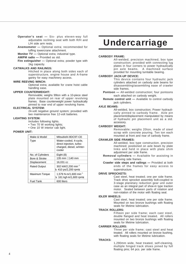
POWER UNIT:
CARBODY FRAME:All-welded, precision machined, box typeconstruction; provided with connecting lugplates in four corners to power hydraulicallypin axle beams. A machined surfaceprovided for mounting turntable bearing.
CARBODY JACK-UP DEVICE:This device contains four hydraulic jackcylinders attached on carbody axle beams fordisassembling/assembling ease of crawlerside frames.
Pontoon — All-welded construction; four pontoonseach attached on carbody weight.
Remote control unit — Available to control carbodyjack cylinders.
AXLE BEAMS:All-welded, box construction; Power hydrauli-cally pinned to carbody frame. Axle pinplacement/displacement manipulated by meansof hydraulic pin placement unit as a std.accessory.
CARBODY WEIGHT:Removable; weighs 20ton, made of steelscrap with concrete pouring. Ten ton eachmounted at front and rear of carbody frame.
CRAWLER SIDE FRAMES:All-welded, box type construction, precisionmachined; positioned on axle beam by platelinks and held in place with plate shimadjustment per side frame.
Removal cylinders — Available for assisting inremoving side frames.
Crawler side steps and railings — Provided at bothends of the frames for easy access tosuperstructure.
DRIVE SPROCKETS:Cast steel, heat treated; one per side frame.Track drive sprocket assembly bolt-coupled to3-stage planetary reduction gear unit outercase as an integral part of shoe-in type tractionmotor. Sealed between parts of rotation andnon-rotation of the motor with floating seal.
IDLER WHEELS:Cast steel, heat treated; one per side frame.Mounted on two bronze bushings with floatingseals for lifetime lubrication.
TRACK ROLLERS:Fifteen per side frame; each cast steel,double flanged and heat treated. All rollersmounted on two bronze bushings with floatingseals for lifetime lubrication.
CARRIER ROLLERS:Three per side frame; cast steel and heattreated. All rollers mounted on bronze bushing,with floating seals for lifetime lubrication.
TRACKS:1,290mm wide, heat treated, self-cleaning,multiple hinged track shoes joined by fullfloating pins; 64 pcs. per side frame.
4
Make & ModelType�
�
No. of CylindersBore & StrokeDisplacement
Rated Output
Maximum Torque
Fuel Tank
Mitsubishi 8DC9T-CEWater-cooled, 4-cycle,�direct injection, turbo-charged, diesel, w/inter-cooler
Eight (8)135 mm × 140 mm
16,031 cc
302 kW/2,200 min–1�
〈410 ps/2,200 rpm〉
1,579 N·m/1,600 min–1�
〈161 kgf-m/1,600 rpm〉 600 liters
Undercarriage

Track adjustment — By manually adjusted with no.of shim plate provided at each idler wheelblock in cooperation with hyd. pin placementunit.
TRAVEL AND STEERING:Hydrostatic drive; a bi-directional, 2-speed,shoe-in type axial piston hydraulic motor bolt-couples drive sprocket thru 3-stage planetaryreduction gear unit outer case at each crawlerside frame end for travel and steer. Straight-l ine travel (forward or reverse), pivot ordifferential turns, and counter-rotation for spinturns available.
Brake — Spring-applied, hydraulically releasedmultiple wet-disc type automatic brake;located within hydraulic motor. Brakesautomatically set when travel levers are inneutral or when engine is shut down.
Travel speed — 1.0km/hr. (High), 0.65km/hr. (Low).— based on flat, level and firm supportingsurface, and under the conditions that no loadmust be applied and front-end att. must bethe 18.0m basic boom only.
Gradeability — 30% (17°) permissible based on basicmachine without front-end attachment.
SML-10 LOAD MOMENT LIMITER:This is a ful ly computerized total safeoperation control system, and automatic over-load preventing system as standardequipment.
Construction (standard version) — Comprises (1)load detecting device, (2) boom angledetector, (3) amplifier, and (4) display panelwith computerized Micro processing Unit(M.P.U).
Functions — This system functions that if a lifting loadreaches a 90% of the rated one specified inthe crane capacity chart, an annunciating pre-warning is given; if it is an 100%, a warning isgiven by red lamp, and annunciating warning,and all peril side motions are automaticallystopped. The machine, however, can beoperated in safety side motions.
Display panel design — The SML-10 is designed tobe able to input the operating conditions/data bysetting keys on LCD 1, and to indicate thepresent lifting conditions/data like “lifting load” ,“rated load”, “working radius” “boom angle”,“engine rpm”, “lifting height (opt.)” and so forthon LCD 2 thru LCD 5. Also, the LCD 1 indicates“load ratio”, and letter messages when themachine becomes abnormal.
HOOK OVER-HOIST LIMITING DEVICE:Limit switch type. Available to prevent hookover-hoisting with functions of automatic drumbraking with hydraulic lock, and warnings by
red lamp and annunciating alarm.BOOM OVER-HOIST AND -LOWERING LIMITING DEVICE:
Available in two kinds of devices; one is limitswitch located on a part of boom foot forpreventing boom over-hoisting, and the otheris the safety function of the SML-10 availableto automatically prevent boom over-hoistingand -lowering with the functions of automaticdrum braking with hydraulic lock, andwarnings by red lamp and annunciating alarm.Further boom protection from rapid boomover-hoist by hook over-hoist motion undermal-function of hook over-hoist limiting deviceis available as one of functions of the SML-10.
BOOM BACKSTOPS:Dual; telescopic design with spring buffers.
DUAL BOOM OVER-HOIST LIMITING DEVICE:Additional l imit switch located on boombackstops; this is as a further safety devicefor redundant boom protection.
SWING LOCK:Mechanically operated drop pin; available tofirmly lock superstructure in four positions offacing front or rear or left or right to undercarriage.
DRUM LOCKS:Electrically operated pawl locks; available onfront and rear main, boom hoist and optional3rd drums. All drum pawl-lockings areautomatically done when control lever returnsinto neutral position.
BOOM ANGLE INDICATOR:Pendulum type; mounted on right-hand side ofbottom section of crane main boom.
HOOK LATCH:Provided on every kinds of hook to preventout of place of cable from hook.
LEVEL GAUGES:Bubble type; both located on operator’s cabfloor of superstructure, and on a part ofundercarriage.
LEVER LOCKS:Provided on drum control levers to lock in neutralposition, and/or to prevent stroke to eitherdirection of lowering or hoisting side.
SWING ALARM:This is by buzzer, and flasher lamps locatedon both sides of machinery cab.
ANNUNCIATING ALARMS:This is one of functions of the SML-10;provided with ten and some kinds of alarms.
SPEED SLOWDOWN DEVICE:This is for speed slowdown of hoisting andlowering motions of crane main boom (and/ortower jib in case of luffing towercrane att.)which are available just before automaticstopping to prevent a shock.
BOOM LIVE MAST LIMIT SWITCH:Available to avoid a flapping of boom livemast when assembling/disassembling boombottom section.
SWING BRAKE LAMP:Provided on operator’s cab instrument panel;this is available to confirm whether or notswing brake is applied.
5
Safety Devices
SIGNAL HORN:Available as warning just before every kindsof motions from operator.
FOOL PROOF SHUT-OFF SYSTEM:Located in the cab exit; this is available toautomatically deactives and locks hydraulicsystem.
TRAVEL ALARM:Buzzer warns when travel motion is initiated.
LIFTING HEIGHT METER:Available to indicate l ift ing height aboveground or depth below ground on LCD 2 ofSML-10 Load Moment Limiter display panel.Also, hook hoisting speed slowdown functionis available just before automatic stopping ata desired height under hook height settingbefore operation.
ENGINE SERVICE MONITOR:Available for checking engine operatingconditions like fuel level, engine oil temp.,radiator coolant level, and so on.
MICROPHONE & LOUD-SPEAKER:This is for operator’s convenience for loudspeaking.
DRUM MIRROR:Available for checking rope winding onto frontand/or rear drum(s).
EMERGENCY MACHINE STOP BUTTONS:Four; three located on super-structure, andthe other one located on center rotary joint ofcarbody frame. Available when it isnecessary to stop all machine motion.
REAR VIEW MIRRORS:Two each provided on front-left and-rightcorners of super-structure.
THREE COLOR PERCENTAGE INDICATOR:Optional extra; this is with three colours ofGreen, Yellow and Red. Each colourindicates the load percentage to ratedcapacity; Green shows less than 90% assafety, Yellow shows 90 to 99% as marginal,and Red shows over 100% as over-loading.As further function, Red lamp comes onautomatically when operator cuts off safetydevice switch absent-mindedly.
DRUM LIGHT:Optional extra; available for checkingfront/rear drum rope winding when nightoperation.
RADIOPHONE:Optional extra; available for a goodcorrespondence among operator, signalmanand other worker (or between operator andsignalman).
MONITOR TV SYSTEM:Optional extra; this is also for operator’sconvenience for checking hook and loadposition thru monitor TV in operator’s cab.
ANNUNCIATING SWING ALARM:Optional extra; this is additional alarm forswing motion with a caution voice of “nowswing, keep clear please!”.
AIRCRAFT WARNING LIGHT:Optional extra; f i t ted on top of l i f tcrane
boom/tower jib to give a warning to aircraftsby a 100W red-color light.
AUX. CRANE HOOK OVER-HOIST LIMITING DEVICE:Optional extra; this is available for auxiliarycrane hoist with optional aux. short j ib.Performs the same function as that of “Hookover-hoist limiting device” mentioned before.
In addition to the above, following safety devices arestandard for luffing towercrane attachment.
TOWER JIB ANGLE DETECTOR:This is one of key safety device in a case ofluffing towercrane attachment.
TOWERCRANE LOAD DETECTOR:This is also important safety device whenluffing towercrane attachment is required.
TOWER JIB OVER-HOIST AND -LOWERING LIMITINGDEVICE:
Performs all the same function as that of“Boom over-hoist and -lowering l imit ingdevice” stated before.
TOWER JIB HOOK OVER-HOIST LIMITING DEVICE:Performs the same function as that of “Hookover-hoist limiting device” described before.
TOWERCRANE ATT. SELF-ERECTION MODE:This is an internal, integral mode as one ofkey function of the SML-10 for safe self-erection and -laying down of luffing towercraneattachment without fail.
THIRD DRUM LOCK:Provided with automatic pawl-locking devicelike other drum pawl-lockings.
TOWER JIB BACKSTOPS:Dual; telescopic design with spring buffers.
DUAL TOWER JIB OVER-HOIST LIMITING DEVICE:Additional limit switch located on tower jibbackstops; this is as a further safety devicefor redundant tower jib protection.
REAR POST BACKSTOPS:Dual; round tubular design with spring buffersat front end, and grease cylinders at rear end.
6

CRANE BOOM:Lattice construction, round tubular main chords, alloy, hi-ten steel, with bracing of round steel tubing.Boom connections........................................In-line pin connections at 2.3m deep by 2.5m wide for heavy-duty booms, and
1.6m deep by 1.85m wide for light-duty booms.Basic boom.................................................Three-piece, 18.0m basic length; 10.5m bottom section, 3.0m tapered boom
extension and 4.5m tapered crane top section. Boom foot pin placed anddisplaced by hyd. pin placement unit.
Boom head machinery ..........................Seven head sheaves and two guide sheaves mounted on anti-frictionbearings.
Add. head sheave block..............................Optional extra; pinned to boom head shaft. Nine sheaves each mounted onanti-friction bearings. This required when lifting load exceeds 180ton.
Heavy-duty boom extensions.......................Optional extra; available in 6.0m and 12.0m lengths with dual pendants.Light-duty boom extension...........................Optional extra; available in 6.0m and 12.0m lengths with dual pendants.Maximum boom length.................................96.0m
AUXILIARY SHORT JIB:Optional extra; all-welded construction having single sheave head machinery. Pinned to 4.5m tapered top section.Available for 13.5ton lift as maximum with single part hoist line.
HOOK BLOCKS:350t, eight sheaves plus a 9-hanger sheave block with duplex hook..............Optional extra.180t, eight sheaves with duplex hook ...............................................................Optional extra; available from a 350ton hook
block by dismounting a nine-hanger sheaveblock.
100t, five sheaves with duplex hook..................................................................Optional extra.65t, three sheaves..............................................................................................Optional extra.13.5t, ball hook ...................................................................................................Optional extra.
BOOM LIVE MAST:All-welded, box type construction, pinned in front of upper revolving frame. This mast attaches bridle with larger sheavesof a 21.4 D/d ratio for 28-part boom hoist rope reeving. Foot pin placed and displaced by hyd. pin placement unit.
MID-POINT SUSPENSION CABLE:Optional extra; required when boom length exceeds 90.0m
BAIL AND BRIDLE:All-welded construction; provided with larger sheaves of a 21.4 D/d ratio on both bail and bridle for 28-part boom hoistrope reeving. Bail pinned to A-frame gantry, and bridle pinned to boom live mast.
DRUM DATA:
Notes:
1. Line speed is based on drum first layer and rated engine rpm.2. Hoisting line speed varies under load and operating conditions.
7
Liftcrane 350 metric tons
Drum Root dia. Type Line speed (Hoisting, Lowering) Cable
Front(main crane hoist)
Rear(aux. crane hoist)
Boom hoist
672mm
672mm
R/H - 541mmL/H - 528mm
Parallel grooved
Parallel grooved
Parallel grooved
130mpm
130mpm
43mpm × 2- line
28mm
28mm
24mm

HOIST REEVING:
CABLES:For front drum…………………………………Nuflex rope with construction of “PS19+39×P7”, spin-resistant type, 28mm
dia./660m long, breaking load 77.0ton.For rear drum…………………………………Optional extra; Nuflex rope with construction of “PS19+39×P7”, spin-resistant
type, 28mm dia./660m long, breaking load 77.0ton.For boom hoist drum…………………………Sraf rope with construction of “IWRC 6×PWS (31)”, 24mm dia./600m long,
breaking load 48.0ton.WORKING WEIGHT:
With 18.0m basic boom, 99ton upper counterweight, 20t carbody weight, 1,290mm wide track shoes and optional 350tonhook block: Approx. 294ton.
GROUND PRESSURE:119.6kPa <1.22kg/cm2> under a 294ton working weight mentioned above.
8
Main crane hoist�Aux. crane �
hoist�
No. of part line�
Max. load (ton)
Main crane hoist�
No. of part line�
Max. load (ton)
32� 31� 30� 29� 28� 27� 26� 25� 24� 23� 22� 21� 20� 19� 18� 17
350.0�348.1�339.9�331.5�323.0�314.4�305.5�296.5�287.3�277.9�268.3�258.5�248.5�238.3�227.9�217.3
16� 15� 14� 13� 12� 11� 10� 9� 8� 7� 6� 5� 4� 3� 2� 1
208.4�195.4�185.9�174.3�162.5�150.4�138.0�125.5�112.6�99.5� 86.1� 72.5� 58.6� 44.4� 29.9� 15.1
1
13.5
9
Liftcrane Capacities
18.0� 24.0� 30.0� 36.0Boom length (m)
Working radius (m)
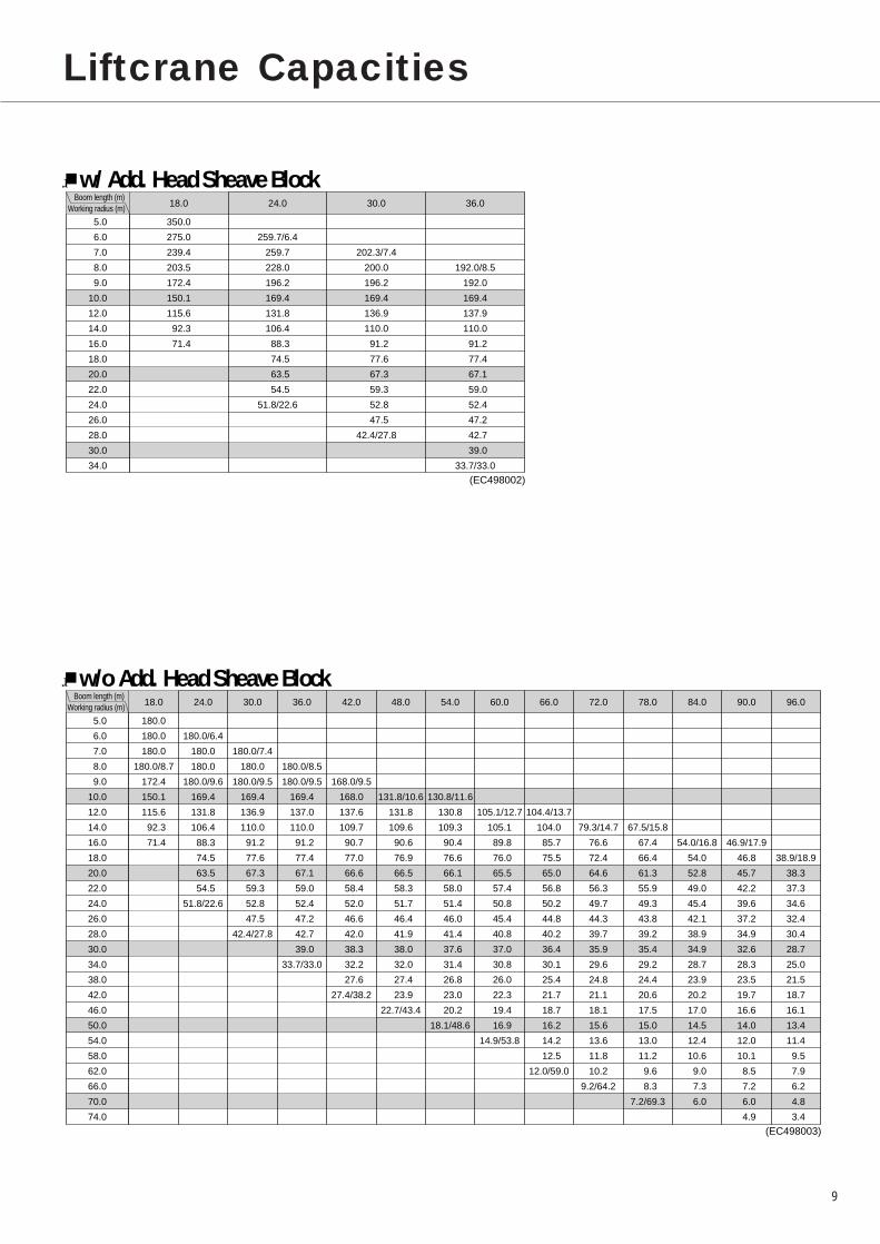
w/ Add. Head Sheave Block
5.0�
6.0�
7.0�
8.0�
9.0�
10.0�
12.0�
14.0�
16.0�
18.0�
20.0�
22.0�
24.0�
26.0�
28.0�
30.0�
34.0
350.0�
275.0�
239.4�
203.5�
172.4�
150.1�
115.6�
92.3�
71.4�
�
259.7/6.4�
259.7�
228.0�
196.2�
169.4�
131.8�
106.4�
88.3�
74.5�
63.5�
54.5�
51.8/22.6�
�
�
202.3/7.4�
200.0�
196.2�
169.4�
136.9�
110.0�
91.2�
77.6�
67.3�
59.3�
52.8�
47.5�
42.4/27.8�
�
�
�
192.0/8.5�
192.0�
169.4�
137.9�
110.0�
91.2�
77.4�
67.1�
59.0�
52.4�
47.2�
42.7�
39.0�
33.7/33.0
(EC498002)
(EC498003)
18.0� 24.0� 30.0� 36.0� 42.0� 48.0� 54.0� 60.0� 66.0� 72.0� 78.0� 84.0� 90.0� 96.0Boom length (m)
Working radius (m)
w/o Add. Head Sheave Block
5.0�
6.0�
7.0�
8.0�
9.0�
10.0�
12.0�
14.0�
16.0�
18.0�
20.0�
22.0�
24.0�
26.0�
28.0�
30.0�
34.0�
38.0�
42.0�
46.0�
50.0�
54.0�
58.0�
62.0�
66.0�
70.0�
74.0
180.0�
180.0�
180.0�
180.0/8.7�
172.4�
150.1�
115.6�
92.3�
71.4�
�
180.0/6.4�
180.0�
180.0�
180.0/9.6�
169.4�
131.8�
106.4�
88.3�
74.5�
63.5�
54.5�
51.8/22.6�
�
�
180.0/7.4�
180.0�
180.0/9.5�
169.4�
136.9�
110.0�
91.2�
77.6�
67.3�
59.3�
52.8�
47.5�
42.4/27.8�
�
�
�
180.0/8.5�
180.0/9.5�
169.4�
137.0�
110.0�
91.2�
77.4�
67.1�
59.0�
52.4�
47.2�
42.7�
39.0�
33.7/33.0�
�
�
�
�
168.0/9.5�
168.0�
137.6�
109.7�
90.7�
77.0�
66.6�
58.4�
52.0�
46.6�
42.0�
38.3�
32.2�
27.6�
27.4/38.2�
�
�
�
�
�
131.8/10.6�
131.8�
109.6�
90.6�
76.9�
66.5�
58.3�
51.7�
46.4�
41.9�
38.0�
32.0�
27.4�
23.9�
22.7/43.4�
�
�
�
�
�
130.8/11.6�
130.8�
109.3�
90.4�
76.6�
66.1�
58.0�
51.4�
46.0�
41.4�
37.6�
31.4�
26.8�
23.0�
20.2�
18.1/48.6�
�
�
�
�
�
�
105.1/12.7�
105.1�
89.8�
76.0�
65.5�
57.4�
50.8�
45.4�
40.8�
37.0�
30.8�
26.0�
22.3�
19.4�
16.9�
14.9/53.8�
�
�
�
�
�
�
104.4/13.7�
104.0�
85.7�
75.5�
65.0�
56.8�
50.2�
44.8�
40.2�
36.4�
30.1�
25.4�
21.7�
18.7�
16.2�
14.2�
12.5�
12.0/59.0�
�
�
�
�
�
�
�
79.3/14.7�
76.6�
72.4�
64.6�
56.3�
49.7�
44.3�
39.7�
35.9�
29.6�
24.8�
21.1�
18.1�
15.6�
13.6�
11.8�
10.2�
9.2/64.2�
�
�
�
�
�
�
�
67.5/15.8�
67.4�
66.4�
61.3�
55.9�
49.3�
43.8�
39.2�
35.4�
29.2�
24.4�
20.6�
17.5�
15.0�
13.0�
11.2�
9.6�
8.3�
7.2/69.3�
�
�
�
�
�
�
�
�
54.0/16.8�
54.0�
52.8�
49.0�
45.4�
42.1�
38.9�
34.9�
28.7�
23.9�
20.2�
17.0�
14.5�
12.4�
10.6�
9.0�
7.3�
6.0�
�
�
�
�
�
�
�
�
46.9/17.9�
46.8�
45.7�
42.2�
39.6�
37.2�
34.9�
32.6�
28.3�
23.5�
19.7�
16.6�
14.0�
12.0�
10.1�
8.5�
7.2�
6.0�
4.9
�
�
�
�
�
�
�
�
�
38.9/18.9�
38.3�
37.3�
34.6�
32.4�
30.4�
28.7�
25.0�
21.5�
18.7�
16.1�
13.4�
11.4�
9.5�
7.9�
6.2�
4.8�
3.4
Notes — Liftcrane capacities1. Capacities included in these charts are the maximum
allowable, and are based on machine standing level on firmsupporting surface under ideal job conditions.
2. Capacities are in metric tons, and are not more than 78% ofminimum tipping loads, or based on the other factor ofmachine structural strength limitation.
3.Capacities are based on freely suspended loads and make noallowance for such factors as the effect of wind, suddenstopping of loads, supporting surface conditions, and operatingspeeds. Operator must reduce load ratings to take suchconditions into account. Deduction from rated capacities mustbe made for weight of hook block, weighted ball/hook, sling,spreader bar, or other suspended gear.Hook block weight is as follows:350t...........6.1ton 180t ..........4.9ton 100t ........2.2ton65t.............1.4ton 13.5t .........0.5ton
4. All capacities are rated for 360° swing.5. Least stable rated condition is over the side.6. Boom live mast is required for all operating conditions.7. Counterweight arrangement must be 99ton on superstructure
and 20ton on carbody frame.8. Mid-point suspension cable is required when boom length
exceeds 90.0m.9. Attachment must be erected and lowered over the ends of
the crawler mounting.10. Main boom length must not exceed 96.0m.
Maximum boom length when mounting auxiliary short jib is90.0m.
11. When handling load off main boom head sheaves in case ofmounting auxiliary short jib, a 900kg plus 13.5t hook blockweight deduction in liftcrane capacities must be made.
12. Boom combination shall be in accordance with manufacture’sstandard described here in “Boom Combination Diagram”.
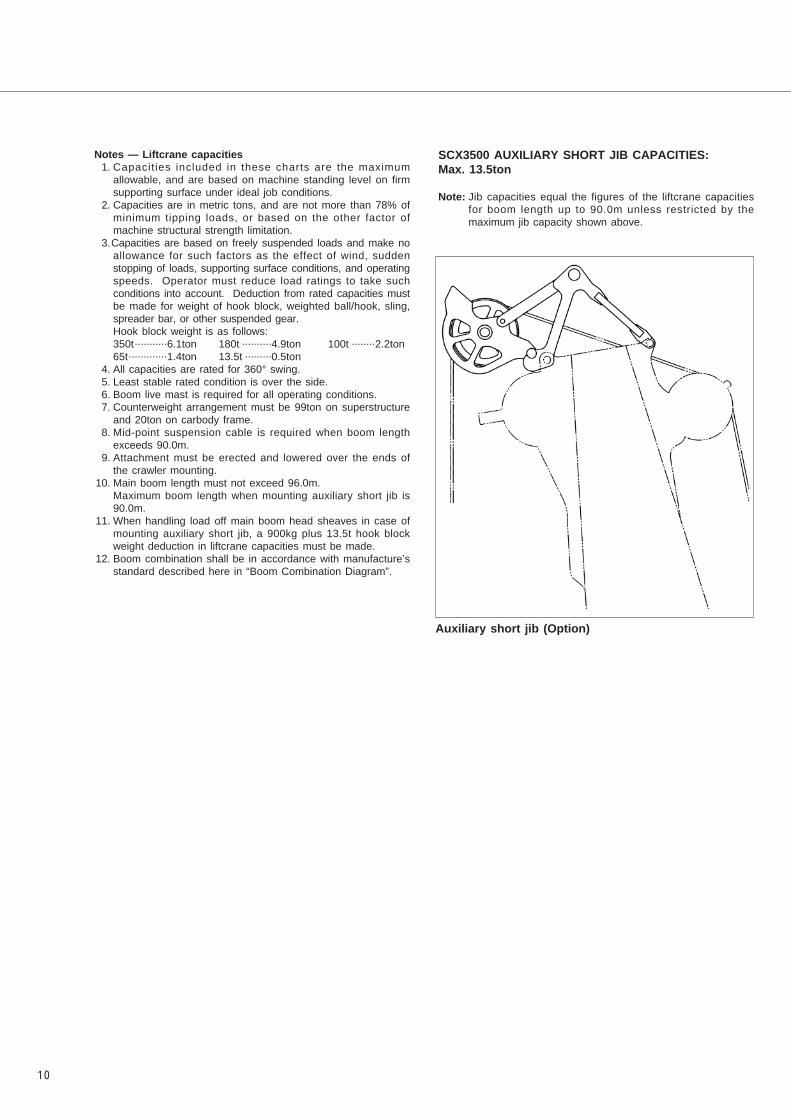
SCX3500 AUXILIARY SHORT JIB CAPACITIES:Max. 13.5ton
Note: Jib capacities equal the figures of the liftcrane capacitiesfor boom length up to 90.0m unless restricted by themaximum jib capacity shown above.
10
Auxiliary short jib (Option)

11
Liftcrane Working Ranges

12
Boom Combination Diagram
Boom length (m)
18.0�
24.0�
30.0�
36.0�
42.0�
48.0�
54.0�
60.0�
66.0�
72.0�
78.0�
84.0�
�
90.0�
96.0
Boom configuration
: 10.5m bottom section�
: 6.0m heavy-duty boom extension�
: 12.0m heavy-duty boom extension�
: 3.0m tapered boom extension�
: 6.0m light-duty boom extension �
: 12.0m light-duty boom extension �
: 4.5m tapered top section �
: Midpoint suspension cable installing position; it is required to install midpoint suspension cable when boom length exceeds 90.0m.
: Extender cables w/two dual of 42mm dia.; the figure each shows the length as follows:�
�� 12� :�12.00m�� 6� :� 6.00m�� 3� :� 3.00m�� 3.6:� 3.65m�� 2� :� 2.10m
Note:�The meanings of figures and symbols shown above are as follows:
6H 12H 12H 12H 12H 3 12L 12L�B
6H
12H
6L
12L
3
�B
T
6 12 12 12 12 2
★
3★
12 12 3.6
T
6H 12H 12H 12H 12H 3 6L 12L�B
T
6 12 12 12 12 2
★
6
6L
6 12 3.6
6H 12H 12H 12H 12H 3 6L 12L�B
T
6 12 12 12 12 2
★
6 12 3.6
6H 12H 12H 12H 12H 3 12L�B
T
6 12 12 12 12 3 12 3.6
6H 12H 12H 12H 12H 3 6L 6L�B
T
6 12 12 12 12 3 6 6 3.6
6H 12H 12H 12H 12H 3 6L�B
T
6 12 12 12 12 3 6 3.6
6H 12H 12H 12H 12H 3�B
T
6 12 12 12 12 3 3.6
12H 12H 12H 12H 3�B
T
12 12 12 12 3 3.6
6H 12H 12H 12H 3�B
T
6 12 12 12 3 3.6
12H 12H 12H 3�B
T
12 12 12 3 3.6
6H 12H 12H 3�B
T
6 12 12 3 3.6
12H 12H 3�B
T
12 12 3 3.6
6H 12H 3�B
T
6 12 3 3.6
12H 3�B
T
12 3 3.6
6H 3�B
T
6 3 3.6
3�B
T
3 3.6Ext. cable configuration
Center of boom foot pin
6.80m

13
Luffing Towercrane General Arrangement
14
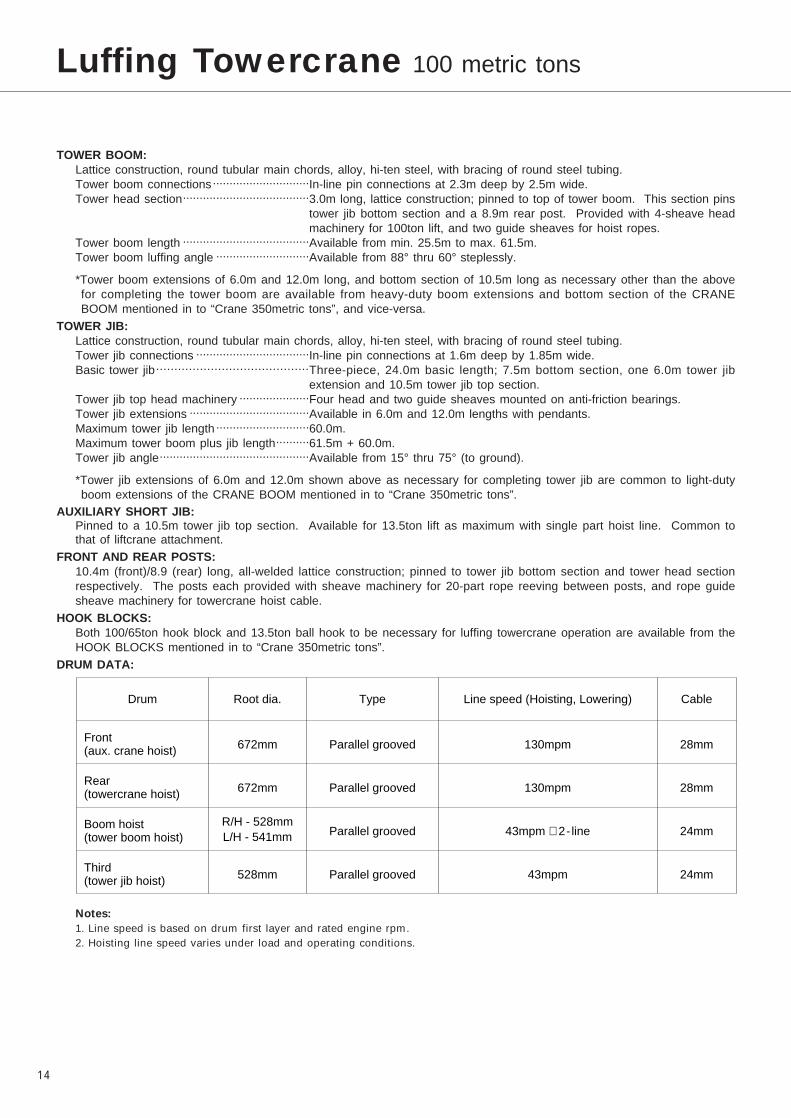
TOWER BOOM:Lattice construction, round tubular main chords, alloy, hi-ten steel, with bracing of round steel tubing.Tower boom connections.............................In-line pin connections at 2.3m deep by 2.5m wide.Tower head section......................................3.0m long, lattice construction; pinned to top of tower boom. This section pins
tower jib bottom section and a 8.9m rear post. Provided with 4-sheave headmachinery for 100ton lift, and two guide sheaves for hoist ropes.
Tower boom length ......................................Available from min. 25.5m to max. 61.5m.Tower boom luffing angle ............................Available from 88° thru 60° steplessly.
*Tower boom extensions of 6.0m and 12.0m long, and bottom section of 10.5m long as necessary other than the abovefor completing the tower boom are available from heavy-duty boom extensions and bottom section of the CRANEBOOM mentioned in to “Crane 350metric tons”, and vice-versa.
TOWER JIB:Lattice construction, round tubular main chords, alloy, hi-ten steel, with bracing of round steel tubing.Tower jib connections ..................................In-line pin connections at 1.6m deep by 1.85m wide.Basic tower jib..........................................Three-piece, 24.0m basic length; 7.5m bottom section, one 6.0m tower jib
extension and 10.5m tower jib top section.Tower jib top head machinery .....................Four head and two guide sheaves mounted on anti-friction bearings.Tower jib extensions ....................................Available in 6.0m and 12.0m lengths with pendants.Maximum tower jib length ............................60.0m.Maximum tower boom plus jib length..........61.5m + 60.0m.Tower jib angle.............................................Available from 15° thru 75° (to ground).
*Tower jib extensions of 6.0m and 12.0m shown above as necessary for completing tower jib are common to light-dutyboom extensions of the CRANE BOOM mentioned in to “Crane 350metric tons”.
AUXILIARY SHORT JIB:Pinned to a 10.5m tower jib top section. Available for 13.5ton lift as maximum with single part hoist line. Common tothat of liftcrane attachment.
FRONT AND REAR POSTS:10.4m (front)/8.9 (rear) long, all-welded lattice construction; pinned to tower jib bottom section and tower head sectionrespectively. The posts each provided with sheave machinery for 20-part rope reeving between posts, and rope guidesheave machinery for towercrane hoist cable.
HOOK BLOCKS:Both 100/65ton hook block and 13.5ton ball hook to be necessary for luffing towercrane operation are available from theHOOK BLOCKS mentioned in to “Crane 350metric tons”.
DRUM DATA:
Notes:
1. Line speed is based on drum first layer and rated engine rpm.2. Hoisting line speed varies under load and operating conditions.
Luffing Towercrane 100 metric tons
Drum Root dia. Type Line speed (Hoisting, Lowering) Cable
Front(aux. crane hoist)
Rear(towercrane hoist)
Boom hoist(tower boom hoist)
Third(tower jib hoist)
672mm
672mm
R/H - 528mmL/H - 541mm
528mm
Parallel grooved
Parallel grooved
Parallel grooved
Parallel grooved
130mpm
130mpm
43mpm × 2- line
43mpm
28mm
28mm
24mm
24mm

15
HOIST REEVING:
CABLES:For front drum…………………………………Nuflex rope with construction of “PS19+39×P7”, spin-resistant type, 28mm
dia./660m long, breaking load 77.0ton.For rear drum…………………………………Nuflex rope with construction of “SP19+39×P7”, spin-resistant type, 28mm
dia./660m long, breaking load 77.0ton.For boom hoist drum…………………………Sraf rope with construction of “IWRC 6×PWS (31)”, 24mm dia./600m long,
breaking load 48.0ton.For third drum…………………………………XP rope with construction of “IWRC 6×PWS (31)”, 24mm dia./540m long,
breaking load 42.5ton.WORKING WEIGHT:
With 61.5m tower boom, 60.0m tower jib, 99ton upper counterweight, 20ton carbody weight, 1,290mm wide track shoesand 100t hook block: Approx. 330ton.
GROUND PRESSURE:134.3kPa <1.37kg/cm2> under a 330ton working weight mentioned above.
Towercrane hoist
No. of part line
Max. load (ton)
Aux. crane hoist
8 7 6 5 4 3 2 1
100.0 99.5 86.1 72.5 58.6 44.4 29.9 15.1
1
13.5
16
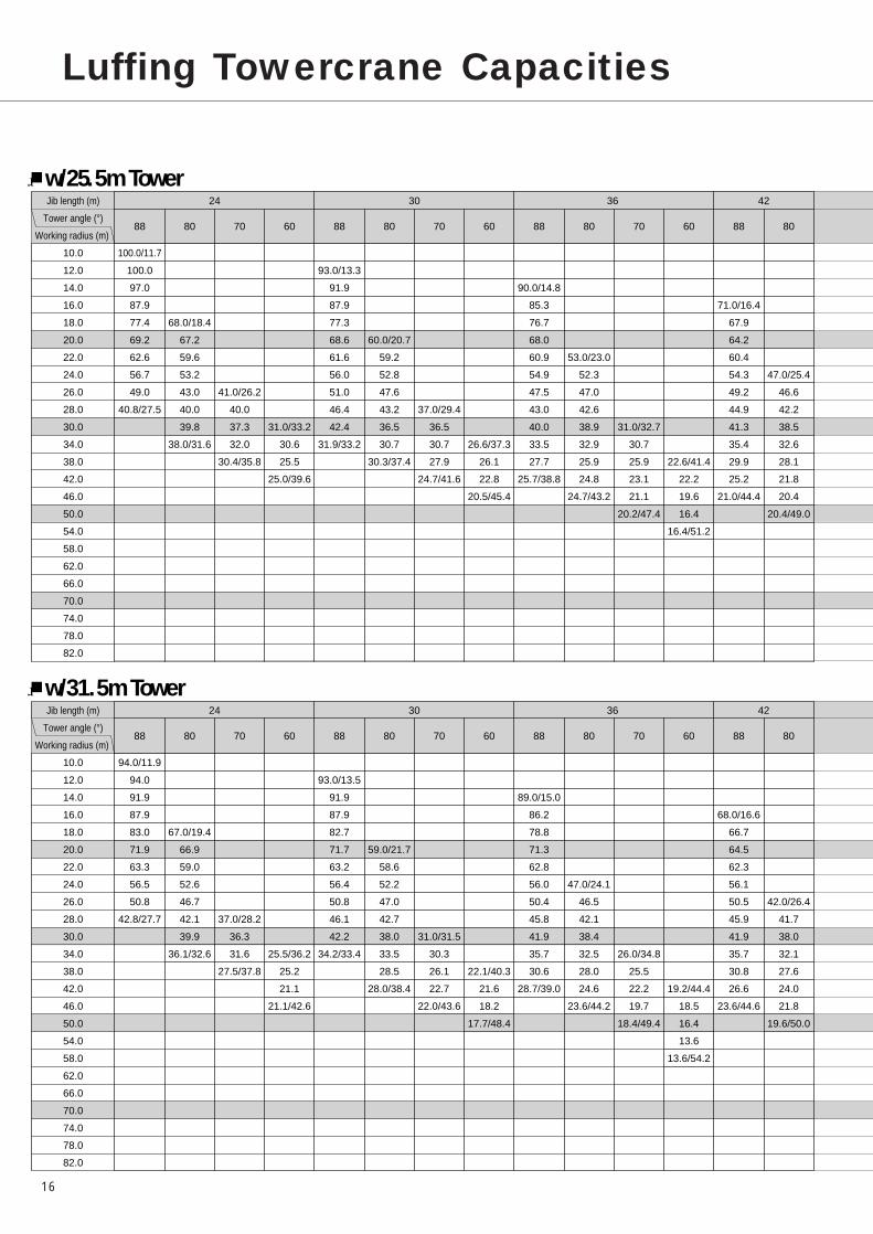
Luffing Towercrane Capacities
w/25.5m TowerJib length (m)
Tower angle (°)
Working radius (m)
24� 30� 36�� 42
88� 80� 70� 60� 88� 80� 70� 60� 88� 80� 70� 60� 88� 80
10.0�
12.0�
14.0�
16.0�
18.0�
20.0�
22.0�
24.0�
26.0�
28.0�
30.0�
34.0�
38.0�
42.0�
46.0�
50.0�
54.0�
58.0�
62.0�
66.0�
70.0�
74.0�
78.0�
82.0
100.0/11.7�
100.0�
97.0�
87.9�
77.4�
69.2�
62.6�
56.7�
49.0�
40.8/27.5�
�
�
�
�
68.0/18.4�
67.2�
59.6�
53.2�
43.0�
40.0�
39.8�
38.0/31.6�
�
�
�
�
�
�
�
�
41.0/26.2�
40.0�
37.3�
32.0�
30.4/35.8�
�
�
�
�
�
�
�
�
�
�
31.0/33.2�
30.6�
25.5�
25.0/39.6�
�
93.0/13.3�
91.9�
87.9�
77.3�
68.6�
61.6�
56.0�
51.0�
46.4�
42.4�
31.9/33.2�
�
�
�
�
�
60.0/20.7�
59.2�
52.8�
47.6�
43.2�
36.5�
30.7�
30.3/37.4�
�
�
�
�
�
�
�
�
�
37.0/29.4�
36.5�
30.7�
27.9�
24.7/41.6�
�
�
�
�
�
�
�
�
�
�
�
26.6/37.3�
26.1�
22.8�
20.5/45.4�
�
�
90.0/14.8�
85.3�
76.7�
68.0�
60.9�
54.9�
47.5�
43.0�
40.0�
33.5�
27.7�
25.7/38.8�
�
�
�
�
�
�
53.0/23.0�
52.3�
47.0�
42.6�
38.9�
32.9�
25.9�
24.8�
24.7/43.2�
�
�
�
�
�
�
�
�
�
�
31.0/32.7�
30.7�
25.9�
23.1�
21.1�
20.2/47.4�
�
�
�
�
�
�
�
�
�
�
�
�
22.6/41.4�
22.2�
19.6�
16.4�
16.4/51.2�
�
�
�
71.0/16.4�
67.9�
64.2�
60.4�
54.3�
49.2�
44.9�
41.3�
35.4�
29.9�
25.2�
21.0/44.4�
�
�
�
�
�
�
�
47.0/25.4�
46.6�
42.2�
38.5�
32.6�
28.1�
21.8�
20.4�
20.4/49.0�
�
�
�
�
�
�
�
�
�
�
�
�
�
�
w/31.5m TowerJib length (m)
Tower angle (°)
Working radius (m)
24� 30� 36�� 42
88� 80� 70� 60� 88� 80� 70� 60� 88� 80� 70� 60� 88� 80
10.0�
12.0�
14.0�
16.0�
18.0�
20.0�
22.0�
24.0�
26.0�
28.0�
30.0�
34.0�
38.0�
42.0�
46.0�
50.0�
54.0�
58.0�
62.0�
66.0�
70.0�
74.0�
78.0�
82.0
94.0/11.9�
94.0�
91.9�
87.9�
83.0�
71.9�
63.3�
56.5�
50.8�
42.8/27.7�
�
�
�
�
67.0/19.4�
66.9�
59.0�
52.6�
46.7�
42.1�
39.9�
36.1/32.6�
�
�
�
�
�
�
�
�
�
37.0/28.2�
36.3�
31.6�
27.5/37.8�
�
�
�
�
�
�
�
�
�
�
�
25.5/36.2�
25.2�
21.1�
21.1/42.6�
�
93.0/13.5�
91.9�
87.9�
82.7�
71.7�
63.2�
56.4�
50.8�
46.1�
42.2�
34.2/33.4�
�
�
�
�
�
59.0/21.7�
58.6�
52.2�
47.0�
42.7�
38.0�
33.5�
28.5�
28.0/38.4�
�
�
�
�
�
�
�
�
�
�
31.0/31.5�
30.3�
26.1�
22.7�
22.0/43.6�
�
�
�
�
�
�
�
�
�
�
�
�
22.1/40.3�
21.6�
18.2�
17.7/48.4�
�
�
89.0/15.0�
86.2�
78.8�
71.3�
62.8�
56.0�
50.4�
45.8�
41.9�
35.7�
30.6�
28.7/39.0�
�
�
�
�
�
�
�
47.0/24.1�
46.5�
42.1�
38.4�
32.5�
28.0�
24.6�
23.6/44.2�
�
�
�
�
�
�
�
�
�
�
�
26.0/34.8�
25.5�
22.2�
19.7�
18.4/49.4�
�
�
�
�
�
�
�
�
�
�
�
�
�
19.2/44.4�
18.5�
16.4�
13.6�
13.6/54.2�
�
�
�
68.0/16.6�
66.7�
64.5�
62.3�
56.1�
50.5�
45.9�
41.9�
35.7�
30.8�
26.6�
23.6/44.6�
�
�
�
�
�
�
�
�
42.0/26.4�
41.7�
38.0�
32.1�
27.6�
24.0�
21.8�
19.6/50.0�
�
�
�
�
�
�
�
�
�
�
�
�
�
�

17
�
�
�
�
�
�
�
�
�
�
�
�
�
�
42� 48� 54� 60
70� 60� 88� 80� 70� 60� 88� 80� 70� 60� 88� 80� 70� 60
Jib length (m)
Tower angle (°)
Working radius (m)
10.0�
12.0�
14.0�
16.0�
18.0�
20.0�
22.0�
24.0�
26.0�
28.0�
30.0�
34.0�
38.0�
42.0�
46.0�
50.0�
54.0�
58.0�
62.0�
66.0�
70.0�
74.0�
78.0�
82.0
�
�
�
�
�
�
�
�
�
�
�
26.0/36.0�
25.9�
21.8�
20.2�
18.4�
16.8/53.2�
�
�
�
�
�
�
�
�
�
�
�
�
�
19.5/45.5�
19.1�
17.0�
15.0�
13.9/57.0�
�
�
�
55.0/17.9�
55.0�
53.9�
52.5�
51.1�
48.5�
44.1�
40.3�
34.1�
29.5�
25.1�
21.4�
17.1�
16.9/50.1�
�
�
�
�
�
�
�
�
42.0/27.7�
41.7�
38.0�
32.0�
27.6�
24.2�
21.4�
16.9�
16.0�
16.0/54.8�
�
�
�
�
�
�
�
�
�
�
�
�
22.0/39.2�
21.9�
19.8�
16.9�
15.9�
14.3�
13.9/59.0�
�
�
�
�
�
�
�
�
�
�
�
�
�
�
16.6/49.6�
16.4�
14.6�
13.0�
10.7�
10.7/62.8�
�
�
�
�
48.0/19.5�
48.0�
44.9�
41.9�
39.3�
36.9�
34.8�
32.2�
28.1�
24.6�
21.3�
18.3�
15.7�
13.9/55.7�
�
�
�
�
�
�
�
�
�
�
32.0/30.1�
31.6�
27.3�
23.9�
20.8�
17.2�
14.2�
13.5�
13.5/60.6�
�
�
�
�
�
�
�
�
�
�
�
�
�
19.0/42.5�
18.7�
17.2�
14.2�
13.5�
12.5�
11.5/64.8�
�
�
�
�
�
�
�
�
�
�
�
�
�
�
�
14.2/53.7�
14.1�
12.6�
11.2�
9.1�
9.1/68.6�
�
�
�
�
�
39.0/21.0�
38.7�
37.8�
36.8�
35.4�
34.0�
32.0�
27.5�
23.5�
20.6�
17.7�
15.2�
13.0�
11.1/61.3�
�
�
�
�
�
�
�
�
�
�
32.0/32.4�
31.1�
26.5�
22.9�
20.0�
16.5�
14.7�
12.2�
10.8�
10.5�
10.0/66.4�
�
�
�
�
�
�
�
�
�
�
�
�
�
19.0/45.8�
18.1�
15.9�
14.7�
12.2�
10.8�
10.0�
8.8�
8.0/70.6�
�
�
�
�
�
�
�
�
�
�
�
�
�
�
�
�
12.0/57.8�
11.8�
10.6�
9.5�
8.3�
6.6�
6.6/74.4�
�
�
�
�
�
�
�
�
�
�
�
�
�
�
42� 48� 54� 60
70� 60� 88� 80� 70� 60� 88� 80� 70� 60� 88� 80� 70� 60
Jib length (m)
Tower angle (°)
Working radius (m)
10.0�
12.0�
14.0�
16.0�
18.0�
20.0�
22.0�
24.0�
26.0�
28.0�
30.0�
34.0�
38.0�
42.0�
46.0�
50.0�
54.0�
58.0�
62.0�
66.0�
70.0�
74.0�
78.0�
82.0
�
�
�
�
�
�
�
�
�
�
�
�
22.0/38.0�
21.7�
19.1�
17.8�
15.7�
15.0/55.2�
�
�
�
�
�
�
�
�
�
�
�
�
�
�
16.6/48.5�
15.9�
14.2�
11.8�
11.7/60.0�
�
�
�
�
54.5/18.1�
53.7�
52.5�
51.3�
49.7�
45.5�
41.6�
35.2�
30.3�
26.5�
22.6�
19.3�
19.0/50.3�
�
�
�
�
�
�
�
�
�
38.0/28.8�
37.5�
31.6�
26.8�
23.5�
20.7�
18.6�
17.1�
16.3/55.8�
�
�
�
�
�
�
�
�
�
�
�
�
22.0/41.3�
21.1�
18.6�
16.5�
14.8�
13.7�
12.6/61.0�
�
�
�
�
�
�
�
�
�
�
�
�
�
�
�
14.1/52.6�
13.5�
12.1�
10.0�
9.7/65.8�
�
�
�
�
48.0/19.7�
47.9�
45.2�
42.4�
39.7�
37.3�
35.1�
31.4�
28.4�
25.8�
22.5�
19.4�
16.6�
15.2/55.9�
�
�
�
�
�
�
�
�
�
�
32.0/31.1�
31.1�
26.6�
23.3�
20.6�
18.4�
15.4�
14.9�
13.6/61.6�
�
�
�
�
�
�
�
�
�
�
�
�
�
19.0/44.6�
18.0�
16.3�
14.6�
13.2�
11.9�
10.7�
10.0/66.8�
�
�
�
�
�
�
�
�
�
�
�
�
�
�
�
�
12.1/56.7�
11.6�
10.3�
9.2�
7.7�
7.3/71.6�
�
�
�
�
�
39.0/21.2�
38.7�
37.8�
36.8�
35.0�
33.8�
31.3�
27.0�
23.5�
20.6�
18.0�
15.7�
13.9�
12.1/61.6�
�
�
�
�
�
�
�
�
�
�
31.0/33.5�
30.6�
26.1�
22.5�
19.6�
17.2�
15.0�
13.0�
12.0�
11.0�
10.5/67.4�
�
�
�
�
�
�
�
�
�
�
�
�
�
�
16.0/47.8�
15.1�
14.3�
12.7�
11.3�
10.1�
9.0�
8.4/72.6�
�
�
�
�
�
�
�
�
�
�
�
�
�
�
�
�
�
10.1/60.8�
9.7�
8.6�
7.6�
6.3�
6.0/77.4�

18
w/37.5m TowerJib length (m)
Tower angle (°)
Working radius (m)
24� 30� 36�� 42
88� 80� 70� 60� 88� 80� 70� 60� 88� 80� 70� 60� 88� 80
10.0�
12.0�
14.0�
16.0�
18.0�
20.0�
22.0�
24.0�
26.0�
28.0�
30.0�
34.0�
38.0�
42.0�
46.0�
50.0�
54.0�
58.0�
62.0�
66.0�
70.0�
74.0�
78.0�
82.0
�
93.0/12.1�
91.9�
87.9�
82.5�
71.5�
63.0�
56.2�
50.5�
45.9/27.9�
�
�
�
�
�
59.0/20.4�
58.2�
51.9�
46.8�
43.5�
37.7�
34.2/33.7�
�
�
�
�
�
�
�
�
�
�
31.0/30.3�
30.6�
24.6�
24.5/39.9�
�
�
�
�
�
�
�
�
�
�
�
�
20.0/39.2�
19.8�
18.5/45.6�
�
93.0/13.7�
91.9�
87.9�
82.3�
71.3�
62.8�
56.0�
50.5�
45.9�
41.9�
35.7/33.6�
�
�
�
�
�
�
52.0/22.8�
51.5�
46.4�
42.1�
38.5�
33.6�
28.9�
27.5/39.5�
�
�
�
�
�
�
�
�
�
�
30.0/33.5�
29.2�
26.1�
21.5�
20.3/45.7�
�
�
�
�
�
�
�
�
�
�
�
�
�
18.4/43.3�
17.9�
15.3�
14.9/51.4�
�
�
88.0/15.2�
86.6�
78.8�
70.9�
62.4�
55.7�
50.1�
45.5�
41.6�
35.4�
30.7�
29.2/39.2�
�
�
�
�
�
�
�
46.0/25.1�
45.8�
41.5�
37.9�
32.1�
27.6�
23.7�
22.5/45.3�
�
�
�
�
�
�
�
�
�
�
�
25.0/36.8�
24.5�
21.3�
19.6�
16.4�
16.0/51.5�
�
�
�
�
�
�
�
�
�
�
�
�
�
�
15.9/47.4�
15.2�
13.2�
12.4/57.2�
�
�
�
68.0/16.8�
67.1�
64.8�
62.5�
55.8�
50.2�
45.6�
41.7�
35.5�
30.7�
27.0�
22.5/44.9�
�
�
�
�
�
�
�
�
42.0/27.5�
41.1�
37.5�
31.6�
27.2�
23.6�
21.7�
18.8�
18.0/51.1�
�
�
�
�
�
�
�
�
�
�
�
�
�
w/43.5m TowerJib length (m)
Tower angle (°)
Working radius (m)
24� 30� 36�� 42
88� 80� 70� 60� 88� 80� 70� 60� 88� 80� 70� 60� 88� 80
10.0�
12.0�
14.0�
16.0�
18.0�
20.0�
22.0�
24.0�
26.0�
28.0�
30.0�
34.0�
38.0�
42.0�
46.0�
50.0�
54.0�
58.0�
62.0�
66.0�
70.0�
74.0�
78.0�
82.0
�
93.5/12.3�
93.0�
91.9�
82.0�
71.1�
62.6�
55.8�
50.2�
45.1�
44.3/28.1�
�
�
�
�
�
58.0/21.5�
57.4�
51.2�
46.1�
41.9�
38.0�
33.2�
32.5/34.7�
�
�
�
�
�
�
�
�
�
�
29.0/32.3�
28.5�
24.3�
22.3/41.9�
�
�
�
�
�
�
�
�
�
�
�
�
�
16.2/42.2�
16.0�
15.7/48.6�
�
93.0/13.9�
93.0�
86.6�
78.8�
70.9�
62.4�
55.7�
50.1�
45.5�
41.6�
35.4/33.8�
�
�
�
�
�
�
51.0/23.8�
50.8�
45.7�
41.5�
37.9�
33.1�
27.5�
26.2/40.5�
�
�
�
�
�
�
�
�
�
�
�
25.0/35.6�
24.1�
21.9�
18.1�
18.0/47.7�
�
�
�
�
�
�
�
�
�
�
�
�
�
�
13.8/46.3�
13.8�
12.2�
12.2/54.4�
�
�
88.0/15.5�
86.6�
78.8�
70.5�
62.0�
55.2�
49.7�
45.2�
41.3�
35.1�
30.3�
28.7/39.4�
�
�
�
�
�
�
�
�
41.0/26.2�
40.9�
37.3�
31.5�
27.1�
23.5�
21.5�
20.0/46.3�
�
�
�
�
�
�
�
�
�
�
�
�
21.0/38.9�
20.3�
17.8�
15.2�
15.0/53.5�
�
�
�
�
�
�
�
�
�
�
�
�
�
�
�
13.1/50.4�
12.4�
10.2�
10.2/60.2�
�
�
�
69.0/17.0�
68.4�
65.2�
62.1�
55.3�
49.8�
45.3�
41.4�
35.2�
30.5�
26.7�
23.3/45.1�
�
�
�
�
�
�
�
�
�
37.0/28.5�
36.8�
31.1�
26.7�
23.2�
21.4�
17.9�
17.0/52.1�
�
�
�
�
�
�
�
�
�
�
�
�
� �

19
�
�
�
�
�
�
�
�
�
�
�
�
�
�
42� 48� 54� 60
70� 60� 88� 80� 70� 60� 88� 80� 70� 60� 88� 80� 70� 60
Jib length (m)
Tower angle (°)
Working radius (m)
10.0�
12.0�
14.0�
16.0�
18.0�
20.0�
22.0�
24.0�
26.0�
28.0�
30.0�
34.0�
38.0�
42.0�
46.0�
50.0�
54.0�
58.0�
62.0�
66.0�
70.0�
74.0�
78.0�
82.0
�
�
�
�
�
�
�
�
�
�
�
�
21.0/40.1�
20.8�
18.2�
16.0�
14.6�
13.8/57.3�
�
�
�
�
�
�
�
�
�
�
�
�
�
�
�
14.1/51.5�
13.1�
11.7�
9.7�
9.5/63.0�
�
�
�
�
54.5/18.3�
53.4�
52.5�
51.6�
49.8�
45.2�
41.3�
35.1�
30.3�
26.6�
23.2�
19.9�
19.4/50.5�
�
�
�
�
�
�
�
�
�
37.0/29.8�
36.9�
31.1�
26.6�
23.1�
20.2�
17.9�
16.5�
15.5/56.9�
�
�
�
�
�
�
�
�
�
�
�
�
�
18.0/43.4�
17.5�
15.4�
13.7�
13.0�
11.5�
11.0/63.1�
�
�
�
�
�
�
�
�
�
�
�
�
�
�
�
�
11.8/55.6�
11.0�
9.8�
8.1�
7.8/68.8�
�
�
�
�
48.5/19.9�
48.5�
45.8�
42.9�
40.1�
37.6�
35.4�
31.7�
28.6�
26.0�
23.3�
20.0�
17.2�
15.8/56.1�
�
�
�
�
�
�
�
�
�
�
31.0/32.2�
30.6�
26.2�
22.7�
19.8�
17.6�
15.8�
14.7�
13.2�
12.0/62.7�
�
�
�
�
�
�
�
�
�
�
�
�
�
�
15.0/46.6�
14.9�
13.5�
12.0�
10.9�
10.1�
9.3/68.9�
�
�
�
�
�
�
�
�
�
�
�
�
�
�
�
�
�
10.0/59.7�
9.3�
8.3�
6.8�
6.1�
5.6/74.6�
�
�
�
�
�
39.0/21.5�
38.7�
37.8�
36.8�
34.0�
32.5�
30.0�
27.0�
23.5�
20.3�
18.0�
15.7�
14.2�
12.0/61.8�
�
�
�
�
�
�
�
�
�
�
�
26.0/34.5�
25.6�
22.1�
19.2�
16.9�
14.9�
13.5�
11.9�
10.7�
10.0/68.5�
�
�
�
�
�
�
�
�
�
�
�
�
�
�
15.0/49.9�
14.3�
12.5�
11.8�
10.6�
9.5�
8.4�
7.5�
7.2/74.7�
�
�
�
�
�
�
�
�
�
�
�
�
�
�
�
�
�
�
8.2/63.8�
7.6�
6.7�
5.9�
4.6�
4.0/80.4
�
�
�
�
�
�
�
�
�
�
�
�
�
�
42� 48� 54� 60
70� 60� 88� 80� 70� 60� 88� 80� 70� 60� 88� 80� 70� 60
Jib length (m)
Tower angle (°)
Working radius (m)
10.0�
12.0�
14.0�
16.0�
18.0�
20.0�
22.0�
24.0�
26.0�
28.0�
30.0�
34.0�
38.0�
42.0�
46.0�
50.0�
54.0�
58.0�
62.0�
66.0�
70.0�
74.0�
78.0�
82.0
�
�
�
�
�
�
�
�
�
�
�
�
�
18.0/42.1�
17.3�
15.2�
13.5�
11.9�
11.0/59.3�
�
�
�
�
�
�
�
�
�
�
�
�
�
�
�
�
11.7/54.5�
10.6�
8.7�
8.4/66.0�
�
�
�
�
56.0/18.6�
55.4�
53.7�
51.9�
49.4�
44.8�
41.0�
34.8�
30.0�
26.4�
23.3�
20.4�
19.6/50.7�
�
�
�
�
�
�
�
�
�
�
31.0/30.9�
30.5�
26.1�
22.6�
19.8�
17.5�
15.7�
14.8/57.9�
�
�
�
�
�
�
�
�
�
�
�
�
�
17.0/45.4�
16.6�
14.6�
12.8�
12.3�
10.1�
10.0/65.1�
�
�
�
�
�
�
�
�
�
�
�
�
�
�
�
�
�
9.7/58.6�
8.8�
7.8�
6.5�
6.0/71.8�
�
�
�
�
�
48.0/20.1�
46.3�
43.5�
40.6�
38.0�
35.8�
31.9�
28.8�
26.1�
23.2�
20.5�
17.7�
16.0/56.3�
�
�
�
�
�
�
�
�
�
�
30.0/33.2�
30.0�
25.7�
22.2�
19.4�
17.0�
15.1�
13.9�
12.7�
12.0/63.7�
�
�
�
�
�
�
�
�
�
�
�
�
�
�
15.0/48.7�
14.1�
12.3�
10.9�
9.8�
8.6�
7.8�
7.0/70.9�
�
�
�
�
�
�
�
�
�
�
�
�
�
�
�
�
�
�
8.1/62.7�
7.3�
6.5�
5.1�
4.6/77.6�
�
�
�
�
�
39.0/21.7�
38.7�
37.8�
36.8�
33.8�
32.0�
29.7�
26.0�
22.5�
19.8�
17.2�
15.5�
14.2�
11.9/62.0�
�
�
�
�
�
�
�
�
�
�
�
26.0/35.5�
25.0�
21.6�
18.8�
16.5�
14.9�
13.4�
11.9�
10.6�
10.0/69.5�
�
�
�
�
�
�
�
�
�
�
�
�
�
�
�
12.0/51.9�
11.7�
10.3�
9.1�
8.1�
7.8�
6.5�
6.0/76.7�
�
�
�
�
�
�
�
�
�
�
�
�
�
�
�
�
�
�
�
6.2/66.8�
5.5�
4.5�
3.4/78.0�

20
w/49.5m TowerJib length (m)
Tower angle (°)
Working radius (m)
24� 30� 36�� 42
88� 80� 70� 60� 88� 80� 70� 60� 88� 80� 70� 60� 88� 80
10.0�
12.0�
14.0�
16.0�
18.0�
20.0�
22.0�
24.0�
26.0�
28.0�
30.0�
34.0�
38.0�
42.0�
46.0�
50.0�
54.0�
58.0�
62.0�
66.0�
70.0�
74.0�
78.0�
82.0
�
90.0/12.6�
90.0�
84.0�
79.0�
71.0�
62.0�
55.0�
50.0�
46.0�
43.9/28.4�
�
�
�
�
�
�
49.0/22.5�
48.0�
46.0�
41.0�
38.0�
32.5�
30.6/35.8�
�
�
�
�
�
�
�
�
�
�
�
24.0/34.4�
23.0�
21.0�
19.9/44.0�
�
�
�
�
�
�
�
�
�
�
�
�
�
16.0/45.2�
15.6�
13.9�
13.2/51.6�
�
�
90.0/14.1�
87.2�
78.8�
70.4�
61.8�
55.1�
49.7�
45.0�
41.3�
35.1/34.0�
�
�
�
�
�
�
�
45.0/24.9�
44.9�
40.7�
37.2�
32.5�
25.8�
24.9/41.6�
�
�
�
�
�
�
�
�
�
�
�
23.0/37.7�
22.9�
20.8�
16.9�
16.4/49.8�
�
�
�
�
�
�
�
�
�
�
�
�
�
�
13.5/49.3�
13.4�
11.0�
10.8/57.4�
�
�
74.0/15.7�
73.4�
69.5�
65.6�
61.7�
55.0�
49.5�
44.9�
41.1�
35.0�
30.2�
28.4/39.6�
�
�
�
�
�
�
�
�
41.0/27.2�
40.1�
36.6�
30.9�
26.6�
22.2�
19.7�
19.5/47.4�
�
�
�
�
�
�
�
�
�
�
�
�
20.0/40.9�
19.2�
16.8�
14.5�
13.0�
13.0/55.6�
�
�
�
�
�
�
�
�
�
�
�
�
�
�
�
10.7/53.4�
10.6�
9.3�
8.3�
8.3/63.2�
�
�
�
76.0/17.2�
73.5�
67.3�
61.1�
54.9�
49.5�
44.8�
41.0�
34.9�
30.1�
26.5�
23.4/45.3�
�
�
�
�
�
�
�
�
�
37.0/29.6�
36.1�
30.5�
26.1�
22.7�
20.9�
17.2�
17.0/53.1�
�
�
�
�
�
�
�
�
�
�
�
�
w/55.5m TowerJib length (m)
Tower angle (°)
Working radius (m)
24� 30� 36�� 42
88� 80� 70� 60� 88� 80� 70� 60� 88� 80� 70� 60� 88� 80
10.0�
12.0�
14.0�
16.0�
18.0�
20.0�
22.0�
24.0�
26.0�
28.0�
30.0�
34.0�
38.0�
42.0�
46.0�
50.0�
54.0�
58.0�
62.0�
66.0�
70.0�
74.0�
78.0�
82.0
�
88.0/12.8�
87.4�
78.0�
72.3�
66.4�
61.5�
54.8�
49.4�
44.7�
42.4/28.6�
�
�
�
�
�
�
47.0/23.6�
46.7�
44.2�
40.0�
36.5�
31.0�
29.0/36.8�
�
�
�
�
�
�
�
�
�
�
�
22.0/36.4�
21.3�
18.5�
17.8/46.0�
�
�
�
�
�
�
�
�
�
�
�
�
�
�
11.7/48.2�
11.7�
10.3�
10.3/54.6�
�
�
77.9/14.3�
74.2�
69.9�
65.6�
61.3�
54.7�
49.2�
44.6�
40.8�
34.7�
34.3/34.2�
�
�
�
�
�
�
�
45.0/25.9�
44.1�
40.0�
36.5�
30.9�
25.5�
22.3�
22.0/42.6�
�
�
�
�
�
�
�
�
�
�
�
�
19.0/39.7�
18.0�
16.0�
14.3�
14.0/51.8�
�
�
�
�
�
�
�
�
�
�
�
�
�
�
�
9.8/52.3�
9.8�
8.7�
8.6/60.4�
�
�
71.0/15.9�
70.7�
70.0�
65.6�
61.2�
54.5�
49.0�
44.5�
40.6�
34.5�
29.9�
27.8/39.8�
�
�
�
�
�
�
�
�
�
36.0/28.3�
34.0�
29.4�
25.5�
22.0�
19.1�
19.0/48.4�
�
�
�
�
�
�
�
�
�
�
�
�
�
16.0/43.0�
15.5�
14.8�
12.2�
11.9/57.6�
�
�
�
�
�
�
�
�
�
�
�
�
�
�
�
�
8.5/56.4�
8.1�
7.2�
6.2�
6.0/66.2�
�
�
�
62.4/17.4�
62.4�
61.7�
60.5�
54.4�
48.9�
44.4�
40.6�
34.4�
29.8�
26.1�
23.2/45.5�
�
�
�
�
�
�
�
�
�
�
30.0/30.6�
28.7�
24.6�
21.9�
20.4�
16.7�
14.8�
14.5/54.2�
�
�
�
�
�
�
�
�
�
�
�

21
�
�
�
�
�
�
�
�
�
�
�
�
�
�
42� 48� 54� 60
70� 60� 88� 80� 70� 60� 88� 80� 70� 60� 88� 80� 70
Jib length (m)
Tower angle (°)
Working radius (m)
10.0�
12.0�
14.0�
16.0�
18.0�
20.0�
22.0�
24.0�
26.0�
28.0�
30.0�
34.0�
38.0�
42.0�
46.0�
50.0�
54.0�
58.0�
62.0�
66.0�
70.0�
74.0�
78.0�
82.0
�
�
�
�
�
�
�
�
�
�
�
�
�
17.0/44.2�
16.3�
14.3�
13.6�
11.2�
11.0/61.4�
�
�
�
�
�
�
�
�
�
�
�
�
�
�
�
�
8.9/57.5�
8.8�
8.4�
6.9�
6.8/69.0�
�
�
�
�
56.7/18.8�
55.7�
53.9�
52.1�
48.9�
44.4�
40.5�
34.4�
29.7�
26.0�
23.1�
20.6�
19.7/50.9�
�
�
�
�
�
�
�
�
�
�
30.0/31.9�
29.8�
25.5�
22.1�
19.3�
17.0�
14.9�
13.4�
13.0/58.9�
�
�
�
�
�
�
�
�
�
�
�
�
�
�
14.0/47.5�
13.6�
12.0�
10.7�
9.5�
8.5�
8.0/67.2�
�
�
�
�
�
�
�
�
�
�
�
�
�
�
�
�
�
7.2/61.6�
7.1�
6.2�
5.3�
4.4�
4.0/74.8�
�
�
�
�
�
49.4/20.3�
46.9�
44.0�
41.1�
38.4�
36.1�
32.2�
29.0�
25.9�
23.0�
20.5�
18.0�
15.3/56.5�
�
�
�
�
�
�
�
�
�
�
�
26.0/34.2�
25.1�
21.7�
18.9�
16.6�
14.7�
14.0�
12.0�
11.5/64.7�
�
�
�
�
�
�
�
�
�
�
�
�
�
�
�
12.0/50.7�
11.5�
10.1�
9.0�
8.7�
7.2�
7.0/73.0�
�
�
�
�
�
�
�
�
�
�
�
�
�
�
�
�
�
�
5.5/65.7�
5.4�
4.5�
3.8�
3.2/78.0�
�
�
�
�
�
39.0/21.9�
38.7�
37.8�
36.8�
33.8�
31.7�
29.0�
26.0�
22.1�
19.0�
16.9�
15.5�
14.2�
11.9�
11.8/62.2�
�
�
�
�
�
�
�
�
�
�
�
25.0/36.6�
23.5�
20.4�
17.7�
15.7�
14.0�
12.5�
11.0�
10.5�
9.5�
9.0/70.5�
�
�
�
�
�
�
�
�
�
�
�
�
�
�
�
�
10.0/54.0�
9.5�
8.4�
7.5�
6.6�
5.8�
5.0�
4.5/78.8
�
�
�
�
�
�
�
�
�
�
�
�
�
�
42� 48� 54� 60
70� 60� 88� 80� 70� 88� 80� 70� 88� 80� 70
Jib length (m)
Tower angle (°)
Working radius (m)
10.0�
12.0�
14.0�
16.0�
18.0�
20.0�
22.0�
24.0�
26.0�
28.0�
30.0�
34.0�
38.0�
42.0�
46.0�
50.0�
54.0�
58.0�
62.0�
66.0�
70.0�
74.0�
78.0�
82.0
�
�
�
�
�
�
�
�
�
�
�
�
�
�
14.0/46.2�
13.4�
11.8�
10.4�
9.2�
9.0/63.4�
�
�
�
�
�
�
�
�
�
�
�
�
�
�
�
�
�
7.0/60.5�
6.4�
5.4�
4.6�
4.4/72.0�
�
�
�
�
54.5/19.0�
54.4�
53.6�
52.2�
48.8�
44.3�
40.4�
34.3�
29.7�
26.0�
23.0�
20.6�
19.8/51.1�
�
�
�
�
�
�
�
�
�
�
29.0/32.9�
28.5�
24.5�
21.3�
18.9�
16.6�
14.4�
13.7�
13.3/60.0�
�
�
�
�
�
�
�
�
�
�
�
�
�
�
13.0/49.5�
12.6�
11.1�
9.8�
9.5�
7.8�
7.5/69.2�
�
�
�
�
�
48.8/20.5�
46.8�
44.2�
41.6�
39.0�
36.5�
32.6�
29.2�
25.6�
22.7�
20.3�
18.2�
15.4/56.8�
�
�
�
�
�
�
�
�
�
�
�
25.0/35.3�
23.7�
20.5�
17.9�
16.0�
14.3�
13.6�
11.2�
11.0/65.8�
�
�
�
�
�
�
�
�
�
�
�
�
�
�
�
11.0/52.8�
10.6�
9.4�
8.3�
8.0�
6.5�
5.8�
5.5/75.0�
�
�
�
�
�
�
38.0/22.1�
37.8�
36.8�
33.8�
31.3�
28.0�
25.2�
22.0�
18.6�
16.9�
15.5�
14.2�
11.9�
11.6/62.4�
�
�
�
�
�
�
�
�
�
�
�
24.0/37.6�
23.1�
20.2�
17.8�
15.6�
13.7�
12.1�
10.7�
9.5�
8.7�
8.5/71.6�
�
�
�
�
�
�
�
�
�
�
�
�
�
�
�
�
9.0/56.0�
8.7�
7.6�
6.7�
5.8�
5.0�
4.2/78.0�

22
w/61.5m TowerJib length (m)
Tower angle (°)
Working radius (m)
30� 36�� 42� 48
88� 80� 70� 88� 80� 70� 88� 80� 70� 88� 80� 70� 88� 80
10.0�
12.0�
14.0�
16.0�
18.0�
20.0�
22.0�
24.0�
26.0�
28.0�
30.0�
34.0�
38.0�
42.0�
46.0�
50.0�
54.0�
58.0�
62.0�
66.0�
70.0�
74.0�
78.0�
82.0
�
�
66.4/14.5�
66.0�
65.6�
65.2�
60.7�
54.1�
48.7�
44.2�
40.3�
34.2�
33.6/34.4�
�
�
�
�
�
�
�
�
40.0/26.9�
39.1�
35.7�
30.2�
25.0�
21.7�
21.0/43.6�
�
�
�
�
�
�
�
�
�
�
�
�
18.0/41.8�
17.6�
16.3�
13.6�
12.9/53.9�
�
�
�
59.3/16.1�
57.2�
56.4�
54.8�
54.0�
48.5�
44.0�
40.2�
34.1�
29.5�
25.8/40.1�
�
�
�
�
�
�
�
�
�
36.0/29.3�
35.0�
29.6�
25.4�
23.0�
18.8�
18.3/49.4�
�
�
�
�
�
�
�
�
�
�
�
�
�
15.0/45.0�
14.7�
13.8�
11.3�
10.2�
10.0/59.7�
�
�
�
50.0/17.6�
50.0�
50.0�
50.0�
50.0�
48.4�
44.0�
40.1�
34.1�
29.5�
25.8�
22.9/45.7�
�
�
�
�
�
�
�
�
�
�
30.0/31.6�
29.1�
24.9�
21.6�
19.9�
16.5�
14.5�
14.0/55.2�
�
�
�
�
�
�
�
�
�
�
�
�
�
�
13.0/48.3�
12.3�
10.8�
10.4�
8.6�
8.2/65.5�
�
�
�
�
43.6/19.2�
43.6�
43.6�
43.6�
43.6�
43.5�
39.7�
33.6�
29.0�
25.4�
22.5�
20.1�
19.3/51.3�
�
�
�
�
�
�
�
�
�
�
�
25.0/34.0�
24.3�
21.0�
18.3�
16.1�
14.0�
12.5�
12.0/61.0�
�
�
�
�
�
�
�
�
�
�
�
�
�
�
�
11.0/51.6�
10.2�
8.9�
8.6�
7.1�
6.2�
6.0/71.3�
�
�
�
�
�
39.4/20.7�
39.4�
39.4�
39.4�
39.4�
37.0�
32.8�
29.0�
25.3�
22.4�
20.0�
18.0�
15.6/57.0�
�
�
�
�
�
�
�
�
�
�
�
24.0/36.3�
23.8�
20.5�
17.9�
15.7�
13.8�
13.2�
10.9�
9.8�
9.5/66.8�
54�
�
�
�
�

23
�
�
�
�
�
�
�
�
�
�
�
�
�
�
54� 60
70� 88� 80� 70
Jib length (m)
Tower angle (°)
Working radius (m)
10.0�
12.0�
14.0�
16.0�
18.0�
20.0�
22.0�
24.0�
26.0�
28.0�
30.0�
34.0�
38.0�
42.0�
46.0�
50.0�
54.0�
58.0�
62.0�
66.0�
70.0�
74.0�
78.0�
82.0
�
�
�
�
�
�
�
�
�
�
�
�
�
�
�
�
9.0/54.8�
8.5�
7.4�
6.3�
5.3�
4.5�
4.0/77.1�
�
�
�
�
�
�
33.8/22.3�
33.8�
31.6�
31.1�
29.1�
25.7�
22.9�
20.6�
18.7�
17.0�
15.6�
14.3�
12.0�
11.6/62.6�
�
�
�
�
�
�
�
�
�
�
�
�
20.0/38.7�
19.9�
17.2�
15.1�
13.2�
11.6�
10.3�
9.3�
8.3�
8.0/72.6�
�
�
�
�
�
�
�
�
�
�
�
�
�
�
�
�
�
7.7/58.1�
6.7�
5.6�
4.6�
4.0�
3.1/78.0�
Notes — Towercrane capacities1. Capacities included in these charts are the maximum allowable, and are
based on machine standing level on firm supporting surface under ideal jobconditions.
2. Capacities are in metric tons, and are based on 78% of minimum tippingloads or based on the other factor of machine structural strength limitation.
3. Capacities are based on freely suspended loads and make no allowance forsuch factors as the effect of wind, sudden stopping of loads, supportingsurface conditions, and operating speeds. Operator must reduce load ratingsto take such conditions into account. Deduction from rated capacities mustbe made for weight of hook block, weighted ball/hook, sling, spreader bar, orother suspended gear. Hook block weight is as follows;100 ............2.2ton 65t .............1.4ton 13.5t.......0.5ton
4. All capacities are rated for 360°swing.5. Least stable rated condition is over the side.6. Boom live mast is required for all operating conditions.7. Counterweight arrangement must be 99ton on superstructure, and 20ton on
carbody frame.8. Attachment must be erected and lowered over the front of the crawler
mounting. When lifting off ground the attachment without any outsideassistance, two steel blocks be placed under track idler wheels each ofcrawler are required.
9. Maximum tower boom and jib combination length permitted is 61.5m towerboom plus 60.0m tower jib. In all tower boom and jib combination up to theavove, auxiliary short jib can be attached on top of tower jib.
10. When handling load off tower jib head sheaves in a case of mountingauxiliary short jib, a 900kg plus 13.5t hook block weight deduction intowercrane capacities must be made.
11. Configuration of attachment shall be in accordance with manufacturer'sstandard described here in “Tower Boom and Jib Combination Table”.
SCX3500 AUXILIARY SHORT JIB CAPACITIES:Max. 13.5ton
Note: Jib capacities equal the figures of the luffing towercrane capacities for alltower boom and jib combination up to 61.5m plus 61.0m unless restrictedby the maximum jib capacity shown above.

24
Luffing Towercrane Working Ranges
Note: The above working range is just under max. tower boom and jib combination i.e. 61.5m tower boom plus 60.0m tower jib.
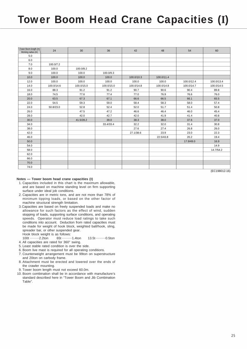
25
Tower Boom Head Crane Capacities (I)
24� 30� 36� 42� 48� 54� 60Tower Boom length (m)
Working radius (m)
5.0�
6.0�
7.0�
8.0�
9.0�
10.0�
12.0�
14.0�
16.0�
18.0�
20.0�
22.0�
24.0�
26.0�
28.0�
30.0�
34.0�
38.0�
42.0�
46.0�
50.0�
54.0�
58.0�
62.0�
66.0�
70.0�
74.0
�
�
100.0/7.2�
100.0�
100.0�
100.0�
100.0�
100.0/14.6�
88.3�
74.5�
63.5�
54.5�
50.8/23.0�
�
�
�
�
100.0/8.2�
100.0�
100.0�
100.0�
100.0/15.0�
91.2�
77.6�
67.3�
59.3�
52.8�
47.5�
42.0�
41.5/28.2�
�
�
�
�
100.0/9.3�
100.0�
100.0�
100.0/15.0�
91.2�
77.4�
67.1�
59.0�
52.4�
47.2�
42.7�
39.0�
33.4/33.4�
�
�
�
�
�
100.0/10.3�
100.0�
100.0/14.8�
90.7�
77.0�
66.6�
58.4�
52.0�
46.6�
42.0�
38.3�
32.2�
27.6�
27.1/38.6�
�
�
�
�
�
100.0/11.4�
100.0�
100.0/14.8�
90.6�
76.9�
66.5�
58.3�
51.7�
46.4�
41.9�
38.0�
32.0�
27.4�
23.9�
22.5/43.8�
�
�
�
�
�
�
100.0/12.4�
100.0/14.7�
90.4�
76.6�
66.1�
58.0�
51.4�
46.0�
41.4�
37.6�
31.4�
26.8�
23.0�
20.2�
17.9/49.0�
�
�
�
�
�
�
100.0/13.4�
100.0/14.5�
89.8�
76.0�
65.5�
57.4�
50.8�
45.4�
40.8�
37.0�
30.8�
26.0�
22.3�
19.4�
16.9�
14.9�
14.7/54.2�
(EC198012-16)
Notes — Tower boom head crane capacities (I)1. Capacities included in this chart is the maximum allowable,
and are based on machine standing level on firm supportingsurface under ideal job conditions.
2. Capacities are in metric tons, and are not more than 78% ofminimum tipping loads, or based on the other factor ofmachine structural strength limitation.
3.Capacities are based on freely suspended loads and make noallowance for such factors as the effect of wind, suddenstopping of loads, supporting surface conditions, and operatingspeeds. Operator must reduce load ratings to take suchconditions into account. Deduction from rated capacities mustbe made for weight of hook block, weighted ball/hook, sling,spreader bar, or other suspended gear.Hook block weight is as follows:100t ..........2.2ton 65t ...........1.4ton 13.5t...........0.5ton
4. All capacities are rated for 360° swing.5. Least stable rated condition is over the side.6. Boom live mast is required for all operating conditions.7. Counterweight arrangement must be 99ton on superstructure
and 20ton on carbody frame.8. Attachment must be erected and lowered over the ends of
the crawler mounting.9. Tower boom length must not exceed 60.0m.
10. Boom combination shall be in accordance with manufacture’sstandard described here in “Tower Boom and Jib CombinationTable”.

26
Tower Boom Head Crane Working Ranges
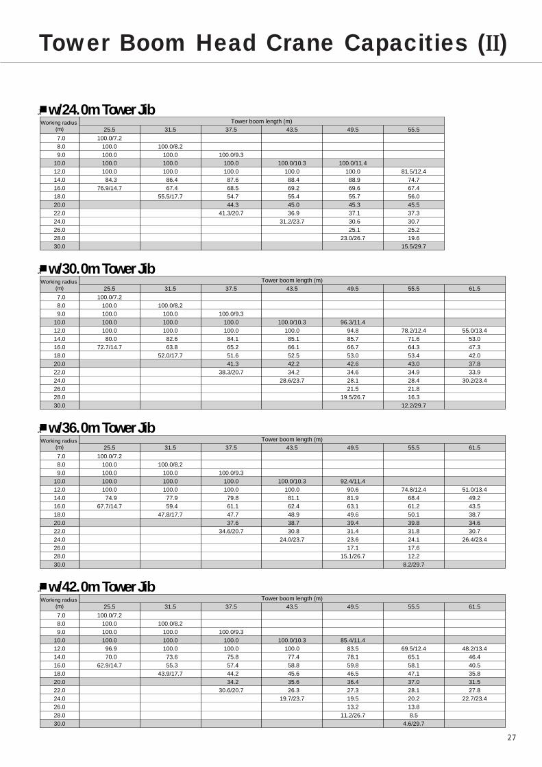
27
Tower Boom Head Crane Capacities (II)
25.5� 31.5� 37.5� 43.5� 49.5� 55.5Working radius �
(m)
w/24.0m Tower Jib
7.0�8.0�9.0�
10.0�12.0�14.0�16.0�18.0�20.0�22.0�24.0�26.0�28.0�30.0
100.0/7.2�100.0�100.0�100.0�100.0�84.3�
76.9/14.7�
�100.0/8.2�
100.0�100.0�100.0�86.4�67.4�
55.5/17.7�
��
100.0/9.3�100.0�100.0�87.6�68.5�54.7�44.3�
41.3/20.7�
���
100.0/10.3�100.0�88.4�69.2�55.4�45.0�36.9�
31.2/23.7�
���
100.0/11.4�100.0�88.9�69.6�55.7�45.3�37.1�30.6�25.1�
23.0/26.7�
����
81.5/12.4�74.7�67.4�56.0�45.5�37.3�30.7�25.2�19.6�
15.5/29.7
Tower boom length (m)
25.5� 31.5� 37.5� 43.5� 49.5� 55.5� 61.5Working radius �
(m)
w/30.0m Tower Jib
7.0�8.0�9.0�
10.0�12.0�14.0�16.0�18.0�20.0�22.0�24.0�26.0�28.0�30.0
100.0/7.2�100.0�100.0�100.0�100.0�80.0�
72.7/14.7�
�100.0/8.2�
100.0�100.0�100.0�82.6�63.8�
52.0/17.7�
��
100.0/9.3�100.0�100.0�84.1�65.2�51.6�41.3�
38.3/20.7�
���
100.0/10.3�100.0�85.1�66.1�52.5�42.2�34.2�
28.6/23.7�
���
96.3/11.4�94.8�85.7�66.7�53.0�42.6�34.6�28.1�21.5�
19.5/26.7�
����
78.2/12.4�71.6�64.3�53.4�43.0�34.9�28.4�21.8�16.3�
12.2/29.7
����
55.0/13.4�53.0�47.3�42.0�37.8�33.9�
30.2/23.4�
Tower boom length (m)
25.5� 31.5� 37.5� 43.5� 49.5� 55.5� 61.5Working radius �
(m)
w/36.0m Tower Jib
7.0�8.0�9.0�
10.0�12.0�14.0�16.0�18.0�20.0�22.0�24.0�26.0�28.0�30.0
100.0/7.2�100.0�100.0�100.0�100.0�74.9�
67.7/14.7�
�100.0/8.2�
100.0�100.0�100.0�77.9�59.4�
47.8/17.7�
��
100.0/9.3�100.0�100.0�79.8�61.1�47.7�37.6�
34.6/20.7�
���
100.0/10.3�100.0�81.1�62.4�48.9�38.7�30.8�
24.0/23.7�
���
92.4/11.4�90.6�81.9�63.1�49.6�39.4�31.4�23.6�17.1�
15.1/26.7�
����
74.8/12.4�68.4�61.2�50.1�39.8�31.8�24.1�17.6�12.2�
8.2/29.7
����
51.0/13.4�49.2�43.5�38.7�34.6�30.7�
26.4/23.4�
Tower boom length (m)
25.5� 31.5� 37.5� 43.5� 49.5� 55.5� 61.5Working radius �
(m)
w/42.0m Tower Jib
7.0�8.0�9.0�
10.0�12.0�14.0�16.0�18.0�20.0�22.0�24.0�26.0�28.0�30.0
100.0/7.2�100.0�100.0�100.0�96.9�70.0�
62.9/14.7�
�100.0/8.2�
100.0�100.0�100.0�73.6�55.3�
43.9/17.7�
��
100.0/9.3�100.0�100.0�75.8�57.4�44.2�34.2�
30.6/20.7�
���
100.0/10.3�100.0�77.4�58.8�45.6�35.6�26.3�
19.7/23.7�
���
85.4/11.4�83.5�78.1�59.8�46.5�36.4�27.3�19.5�13.2�
11.2/26.7�
����
69.5/12.4�65.1�58.1�47.1�37.0�28.1�20.2�13.8�8.5�
4.6/29.7
����
48.2/13.4�46.4�40.5�35.8�31.5�27.8�
22.7/23.4�
Tower boom length (m)

28
25.5� 31.5� 37.5� 43.5� 49.5� 55.5� 61.5Working radius �
(m)
w/48.0m Tower Jib
7.0�8.0�9.0�
10.0�12.0�14.0�16.0�18.0�20.0�22.0�24.0�26.0�28.0�30.0
100.0/7.2�100.0�100.0�100.0�93.7�67.0�
60.0/14.7�
�100.0/8.2�
100.0�100.0�97.8�70.9�52.8�
41.5/17.7�
��
100.0/9.3�100.0�100.0�73.4�55.1�42.0�31.2�
27.7/20.7�
���
100.0/10.3�94.8�75.1�56.8�43.6�33.3�23.7�
17.1/23.7�
���
81.0/11.4�80.2�73.0�57.8�44.6�34.5�24.9�17.1�10.8�
8.9/26.7�
����
65.0/12.4�61.2�55.9�45.3�35.3�
28.9/21.3�
����
46.7/13.4�44.7�39.1�34.4�30.0�26.2�
20.5/23.4�
Tower boom length (m)
25.5� 31.5� 37.5� 43.5� 49.5� 55.5� 61.5Working radius �
(m)
w/54.0m Tower Jib
7.0�8.0�9.0�
10.0�12.0�14.0�16.0�18.0�20.0�22.0�24.0�26.0�28.0�30.0
100.0/7.2�100.0�100.0�100.0�89.0�62.6�
55.7/14.7�
�100.0/8.2�
100.0�100.0�93.6�67.1�49.2�
37.5/17.7�
��
100.0/9.3�100.0�96.6�69.8�51.8�38.9�26.9�
23.4/20.7�
���
96.1/10.3�88.1�71.8�53.7�40.7�29.2�19.8�
13.3/23.7�
���
77.1/11.4�75.0�68.3�54.9�41.8�30.7�21.2�13.6�7.4�
5.5/26.7�
����
60.2/12.4�55.5�51.2�42.7�31.8�
25.3/21.3�
����
44.2/13.4�42.3�36.7�31.8�27.6�22.8�
17.3/23.4�
Tower boom length (m)
25.5� 31.5� 37.5� 43.5� 49.5� 55.5� 61.5Working radius �
(m)
w/60.0m Tower Jib
7.0�8.0�9.0�
10.0�12.0�14.0�16.0�18.0�20.0�22.0�24.0�26.0�28.0�30.0
100.0/7.2�100.0�100.0�100.0�83.1�57.2�
50.4/14.7�
�100.0/8.2�
100.0�100.0�88.4�62.2�44.6�
31.2/17.7�
��
100.0/9.3�100.0�91.7�65.4�47.7�33.2�21.4�
18.0/20.7�
���
91.3/10.3�82.3�67.7�49.8�36.0�24.1�14.9�
8.5/23.7�
���
69.8/11.4�67.8�61.4�51.3�37.8�
29.7/19.3�
����
53.9/12.4�49.7�44.7�39.2�27.2�
20.9/21.3�
����
39.8/13.4�38.3�32.9�28.2�24.2�18.6�
13.2/23.4�
Tower boom length (m)
Notes — Tower boom head crane capacities (II)1. These capacities shown above apply to the operation of
handling load off tower boom head sheaves under the conditionthat tower jib is attached on tower boom, and its offset angle is13 degrees to tower boom.
2. Capacities included in these charts are the maximum allowable,and are based on machine standing level on firm supportingsurface under ideal job conditions.
3. Capacities are in metric tons, and are not more than 78% ofminimum tipping loads, or based on the other factor of machinestructural strength limitation.
4.Capacities are based on freely suspended loads and make noallowance for such factors as the effect of wind, sudden stoppingof loads, supporting surface conditions, and operating speeds.Operator must reduce load ratings to take such conditions intoaccount. Deduction from rated capacities must be made forweight of hook block, weighted ball/hook, sling, spreader bar, orother suspended gear.
Hook block weight is as follows:100t...........2.2ton 65tz .........1.4ton 13.5t...........0.5ton
5. All capacities are rated for 360° swing.6. Least stable rated condition is over the side.7. Boom live mast is required for all operating conditions.8. Counterweight arrangement must be 99ton on superstructure
and 20ton on carbody frame.9. Attachment must be erected and lowered over the ends of the
crawler mounting.10. Tower boom length must not exceed 61.5m.11. Boom combination shall be in accordance with manufacture’s
standard described here in “Tower Boom and Jib CombinationTable”.

29
Tower Boom and Jib Combination Table
Combination TableJib length (m)
Tower length (m)24.0� 30.0� 36.0� 42.0� 48.0� 54.0� 60.0
25.5�
31.5�
37.5�
43.5�
49.5�
55.5�
61.5
◎
◎
◎
◎
◎
◎
×
◎
◎
◎
◎
◎
◎
○
◎
◎
◎
◎
◎
◎
○
◎
◎
◎
◎
◎
◎
○
◎
◎
◎
◎
◎
○
○
◎
◎
◎
◎
◎
○
○
◎
◎
◎
◎
○
○
○
Note:The meanings of symbols shown in the above table is as follows;
1. Symbol of “◎” :Possible to luff tower boom between 88° thru 60°;2. Symbol of “○” :Possible to luff tower boom between 88° thru 70°;3. Symbol of “×” :Impossible to make its tower boom and jib combination.4. Combinations surrounded by bold line indicate that it is possible to internally store the jib under the tower boom.
Length (m)
25.5
31.5
37.5
43.5
49.5
55.5
61.5
Configuration
: 10.5m tower boom bottom section
: 6.0m heavy-duty boom extension
: 12.0m heavy-duty boom extension
: 3.0m tower head section
: Jib extender cable w/two of 54mm dia.; the figure each shows the length in meter.
: Boom extender cable w/two dual of 42mm dia.; the figure each shows the length in meter.
Note:�The meanings of figures and symbols shown above are as follows:
12H
12H
12H 12HB
B
12 12 12 12
12 12 12
6H
6H
12H 12HB
6 12 12 12
6
126
12 12 12
12H 12HB
12 12 12
12
6H 12HB
6 12 12
12HB
12 12
12
6HB
6 12
B
12
10
10
12 12 10
12 10
10
10
Boom extender cable configuration
Jib extender cable configuration
Center of boom foot pin
6.80m
12H 3
12H 3
12H 3
12H 3
12H 3
12H 3
6
106
Tower Boom Configuration
12H 3
3
Length (m)
24.0
30.0
36.0
42.0
48.0
54.0
60.0
Configuration
: 7.5m tower jib bottom section
: 6.0m light-duty boom extension
: 12.0m light-duty boom extension
: 10.5m tower jib top section: 9.65m tower jib extender cable w/two dual of 42mm dia.
: 6.00m tower jib extender cable w/two dual of 42mm dia.
: 12.00 tower jib extender cable w/two dual of 42mm dia.
: 4.90m tower jib extender cable w/two of 54mm dia.
Note:�The meanings of figures and symbols shown above are as follows:
Tower Jib Configuration
12L
6L
JB
6
12
4.9
Extender cable configuration
12 12
6 12 12 12
6
6
6
12
12 12
6
6
12
12 12
12
12
12
6
6
12
12
12
12
12
12JB
JB
JB
JB
JB
JB
JB
T
T
9.6
9.6
T
9.6
T
9.6
T
9.6
T
9.6
T
T
9.6
9.6
4.9
4.9
12 12
12 12 12
12JB
T
9.64.9
4.9
4.9
12
12 12
12JB
T
9.64.9
4.9
4.9
4.9
66
6 6JB
T
9.64.9
66
6 6
66
6 6

30
Standard equipment Optional equipment
Standard and Optional Equipment
]Wire reeving winch w/8mm dia. by 250mlong cable;
]Anemometer; recommended for towercrane operation;
]Fire extinguisher;
]Monitor TV system;
Superstructure ]Mitsubishi 8DC9T-CE diesel engine with a 302kW<410ps> rated output;
]Hydraulic system with two duplicate tandemvariable displacement axial piston pumps and oneguadruplicate tandem pump including one variabledisplacement axial piston pump and one fixeddisplacement triplicate tandem gear pump;
]Control system with one set of triplicate and threesets of duplicate tandem valves and floor typecontrol levers;
]Motorcycle type “SC” controller (easy-precise-minute engine rpm and hyd. pump oil flow controldevice);
]Front and rear main operating drum winches with672mm dia. drum lagging driven by two inde-pendent variable hyd. motors; provided withautomatic brake and drum roller;
]Hydrostatic boom hoist mechanism with a twindrum driven by two hyd. motors with automaticbrake; provided with drum roller. Mounted on A-frame gantry;
]Hydrostatic swing mechanism with double-rowroller type turntable bearing; driven by three hyd.motors w/manually controlled multiple wet-discbrake; provided with constant swing speedmechanism;
]Power hydraulically retractable A-frame gantry withbail assembly;
]All new stamped, automotive type, full-vision,swing-away operator's cab with large curved frontwindow; provided with an arrangement of controlsystem and instrument panel;
]99ton upper counterweight;]Catwalk and railings w/steps along both sides
each of machinery cab and A-frame gantry;]24-volt electrical system with two 12-volt batteries;]Lighting system:
• Two 70W working lights;• One 10W interior cab light;
]Accessories:• Built-in type full air-conditioning;• Engine tachometer;• Fuel gauge;• Thermometer;• Hyd. oil temp. gauge;• Pilot line pressure gauge;• DC 24-volt electric wall outlet;• Foot throttle;• Intermittent window shield wipers with washers;• AM/FM radio w/clock;• Re-fuel pump;• Cigar lighter;• Ash tray;• Book holder;• Sunvisor;• Sunshade;• Cup Holder;• Cab front step;• Cab floor mat;• Hydraulic pin placement unit;• Superstructure under-cover;• Special instruments/tools for machine assembling;• Std. spare parts and tools.

31
Standard equipment Optional equipment
Undercarriage ]7,500mm gauge by 10,135mm long crawlerlower with removable side frames and axlebeams;
]Hydrostatic crawler drive units with shoe-in type2-speed traction motor with wet-disc typeautomatic brakes;
]Carbody jack-up device w/4-vertical hyd. jack-up cylinder and remote control unit;
]Side frame removal/retract cylinders;]20ton carbody weight;]1,290mm wide track shoes;]Lifetime lubricated track components;]Crawler side steps and railings;
Liftcrane Att. ]18.0m basic crane boom; 10.5m bottomsection, 3.0m tapered boom extension and4.5m tapered crane top section w/seven headand two guide sheaves;
]Boom live mast with bail and bridle assembly;]Main crane hoist cable; 28mm dia./660m long;]Boom hoist cable; 24mm dia./600m long.
]6.0m heavy-duty boom extension;
]12.0m heavy-duty boom extension;
]6.0m light-duty boom extension;
]12.0m light-duty boom extension;
]Auxiliary short jib;
]350ton hook block;
]180ton hook block; available from 350tonhook block;
]100ton hook block;
]65ton hook block;
]13.5ton ball hook;
]Add. head sheave block; required whenlifting load exceeds 180ton together with350ton hook block;
]Mid-point suspension cable; required whenboom length exceeds 90.0m.
]Aux. crane hoist cable, 28mm dia./660mlong;

32
Standard equipment Optional equipment
Luffing Towercrane Att.
Safety Devices ]SML-10 Load Moment Limiter; this is a computerizedautomatic over-load preventing system with an all-machine-control purpose computer;
]Lifting height meter;]Three color percentage indicator;]Sixteen kinds of annunciating alarms;]Main and aux. drum pawl locks (w/automatic
pawl-locking device);]Boom hoist drum pawl lock (w/automatic pawl-
locking device);]Swing lock;]Swing alarm;]Hook over-hoist limiting device;]Boom over-hoist and -lowering limiting device;]Dual boom over-hoist limiting device;]Boom backstops;]Boom live mast limit switch;]Speed slowdown device;]Boom angle indicator;]Level gauge; fitted on both floor of operator’s
cab, and on carbody axle beam;]Swing brake lamp;]Signal horn;]Travel alarm;]Hook latch;]Control lever locks;]Fool proof shut-off system;]Engine service monitor.]Microphone & loud-speaker;]Drum mirror;]Emergency machine stop buttons;]Rear view mirrors.
]3.0m tower head section;]Front and rear posts;]24.0m basic tower j ib; 7.5m bottom
section, one 6.0m jib extension and 10.5mtop section;
]6.0m tower jib extension;]12.0m tower jib extension;]Hydrostatic third drum winch mechanism
with automatic brake;]Third drum winch cable, 24mm dia./540m
long;]Towercrane hoist cable, 28mm dia./660m
(as same as optional aux. crane hoist cableof 28mm dia./660m long of liftcrane att.);
]100ton hook block (as same as optional100ton hook block of liftcrane att.);
Note:1. Boom bottom section of 10.5m and HD
boom extensions of 6.0m and 12.0m asnecessary to complete tower boom areavailable from those of liftcrane att.except 3.0m tower head section.
2. Tower jib extensions of 6.0m and 12.0m,are same as those of light-duty boomextensions of 6.0m and 12.0m, ofliftcrane att.
]Monitor TV system;]Annunciating swing alarm;]Aux. hook over-hoist limiting device;]Drum light.
Followings are standard in case of luffingtower-crane attachment:
]Tower jib angle detector;]Towercrane load detector;]Tower jib hook over-hoist limiting device;]Tower jib over-hoist and -lowering limiting
device;]Towercrane att. self-erection mode;]Third drum pawl lock (w/automatic pawl-
locking device);]Tower jib backstops;]Dual tower jib over-hoist limiting device;]Rear post backstops.

33
Transport Data
DescriptionDimensions�
L × W × H (cm)Net weight (kg)Q’ty
Bas
ic m
ach
ine
Lu
ffin
g t
ow
ercr
ane/
Lif
tcra
ne
atta
chm
ents
Basic machine (w/carbody frame & operator’s cab)
Sub frame ass’y (w/F&R drums and diesel-hyd. power pack)
Crawler side frame
Crawler axle beam (w/carbody jack-up cyl.)
Counterweight (base)
Counterweight (mid.)
Counterweight (top)
Carbody weight
A-frame ass’y (w/BH drum & bail/bridle ass’y)
Bottom sect.
Top sect. (w/pendant ropes)
3m tapered boom ext. (w/pendant ropes)
6m HD boom ext. (w/pendant ropes)
12m HD boom ext. (w/pendant ropes)
6m LD boom ext. (w/pendant ropes)
12m LD boom ext. (w/pendant ropes)
350t hook block
180t hook block
100t hook block
65t hook block
13.5t ball hook
Aux. short jib
Boom live mast
Tower head sect.
Tower jib top sect.
1�
1
2�
2�
1�
8�
1�
2�
1�
1�
1�
1�
1�
1�
1�
1�
1�
1�
1�
1�
1�
1�
1�
1�
1
988�
578
@1014�
@805�
550�
@550�
550�
@232�
755�
1075�
527�
336�
615�
1215�
615�
1215�
376�
289�
239�
215�
129�
153�
1340�
374�
1150
32000�
24000
@30000�
@12700�
10800�
@9800�
9800�
@10000�
15200�
7200�
10100
3100�
1400�
2190�
3850�
1640�
2890�
6100�
4900�
2200�
1400�
500�
410�
5000�
3240�
4100
�
�
�
�
�
�
�
�
�
�
�
�
�
�
�
�
�
�
�
�
�
�
�
�
�
�
�
�
�
�
�
�
�
�
�
�
�
�
�
�
�
�
�
�
�
�
�
�
�
�
320
320�
129�
200�
172�
144�
144�
121�
316�
264�
200�
199
264�
264
199�
199�
222�
104
86�
52�
42�
130�
270�
264�
200
335�
202�
155�
139�
139�
32�
32�
118�
217�
270�
256�
244
244�
244�
174�
174�
88
88
88
84�
42�
116�
122�
228�
235
Tower jib bottom sect. (w/F&R posts) 1 1185 8950� �262 362
(w/backstops)�
(w/backstops & 3rd drum winch unit)

¥We are constantly improving our products and therefore reserve the right to change designs and specifications without notice.¥Units in this specification are shown under International System of Units; the figures in parenthesis are under GravitationalSystem of Units as old one.
Printed in Japan
Address Inquires to:
L588-0902(R)