hitachi storage replication adapter for vmware® vcenter ... · deployment guide this document...
TRANSCRIPT
Deployment Guide
This document provides deployment and implementation information for VMware® vCenter Site Recovery Manager™ 5.x/ 6.x using Hitachi Storage Replication Adapter 2.x.
MK-09RM6745-13September 2017
Hitachi Storage Replication Adapter for VMware® vCenter Site Recovery Manager™ 02.03.01

© 2009, 2017 Hitachi, Ltd. All rights reserved.
No part of this publication may be reproduced or transmitted in any form or by any means, electronicor mechanical, including copying and recording, or stored in a database or retrieval system forcommercial purposes without the express written permission of Hitachi, Ltd., or Hitachi VantaraCorporation (collectively “Hitachi”). Licensee may make copies of the Materials provided that any suchcopy is: (i) created as an essential step in utilization of the Software as licensed and is used in noother manner; or (ii) used for archival purposes. Licensee may not make any other copies of theMaterials. “Materials” mean text, data, photographs, graphics, audio, video and documents.
Hitachi reserves the right to make changes to this Material at any time without notice and assumesno responsibility for its use. The Materials contain the most current information available at the timeof publication.
Some of the features described in the Materials might not be currently available. Refer to the mostrecent product announcement for information about feature and product availability, or contactHitachi Vantara Corporation at https://support.hitachivantara.com/en_us/contact-us.html.
Notice: Hitachi products and services can be ordered only under the terms and conditions of theapplicable Hitachi agreements. The use of Hitachi products is governed by the terms of youragreements with Hitachi Vantara Corporation.
By using this software, you agree that you are responsible for:1. Acquiring the relevant consents as may be required under local privacy laws or otherwise from
authorized employees and other individuals to access relevant data; and2. Verifying that data continues to be held, retrieved, deleted, or otherwise processed in
accordance with relevant laws.
Notice on Export Controls. The technical data and technology inherent in this Document may besubject to U.S. export control laws, including the U.S. Export Administration Act and its associatedregulations, and may be subject to export or import regulations in other countries. Reader agrees tocomply strictly with all such regulations and acknowledges that Reader has the responsibility to obtainlicenses to export, re-export, or import the Document and any Compliant Products.
2Hitachi Storage Replication Adapter for VMware® vCenter Site Recovery Manager™ Deployment Guide

Contents
Preface................................................................................................. 7Intended audience................................................................................................... 8Product version........................................................................................................8Release notes.......................................................................................................... 8Changes in this release.............................................................................................8Document conventions............................................................................................. 8Conventions for storage capacity values.....................................................................9Accessing product documentation........................................................................... 10Getting help...........................................................................................................10Comments.............................................................................................................11
1 Overview.............................................................................................13About Hitachi Storage Replication Adapter and Site Recovery Manager.......................14
VMware vCenter infrastructure...........................................................................14Hitachi storage and replication software products................................................14
Command Control Interface (CCI)........................................................................... 16How the VMware® vCenter SRM™/SRA solution works.............................................17
2 Requirements, planning, and prerequisites.............................................19Requirements........................................................................................................ 20SRA/VMware® vCenter SRM™/CCI location options..................................................22Test options...........................................................................................................23
Using the S-VOL for testing............................................................................... 23Required configuration for testing with S-VOL................................................23
Using a copy of the S-VOL for testing.................................................................24Required configuration for testing with a copy of S-VOL................................. 24ShadowImage port requirement................................................................... 24
Configurations with protected and recovery VMs on the same site............................. 25Consistency groups and VM failover groups..............................................................25Consistency groups and same-time split operations.................................................. 25About the TrueCopy fence level “Never”...................................................................26Prerequisites for global-active device configuration................................................... 26
3Hitachi Storage Replication Adapter for VMware® vCenter Site Recovery Manager™ Deployment Guide

AMS 2000 host group options................................................................................. 28
3 Deployment.........................................................................................31Deployment workflow.............................................................................................32Installing CCI.........................................................................................................33Creating and configuring a command device............................................................ 33Setting up HORCM configuration definition files........................................................ 36
Editing HORCM.conf files...................................................................................36Primary HORCM file.....................................................................................38Secondary HORCM file.................................................................................39In-system test copy HORCM file................................................................... 41
Starting HORCM instances, creating pairs.................................................................41Creating a copy for testing on the recovery site.................................................. 42
Setting environment variables................................................................................. 43Defining environment variables using the GUI.....................................................44About SSH........................................................................................................45
Configuring SRA for testing.....................................................................................46Setting environment variables on the VMware® vCenter SRM™ host....................46Setting environment variables on a UNIX Host.................................................... 47
SRA installation......................................................................................................47Installing Hitachi SRA 2.x.................................................................................. 48Removing an earlier version of SRA....................................................................48Checking the SRA version..................................................................................49
To check the SRA version on a Windows server............................................. 49To check the SRA version on a Linux server...................................................49
Configuring SRM™ to communicate with RMSRA20 (SRM 5.x or earlier)..................... 50Enabling array managers...................................................................................54Verifying devices...............................................................................................54
Configuring SRM to communicate with RMSRA20 (SRM 6.0 or later).......................... 56Add array manager........................................................................................... 56
Command device authentication...................................................................62Check devices...................................................................................................63
Performing reprotect and failback............................................................................64
4 Troubleshooting...................................................................................67Error messages on VMware® vCenter SRM™ log files...............................................68
XML errors received from VMware® vCenter SRM™............................................ 68CCI command errors in rmsra20.exe.............................................................70Configuration and status errors.................................................................... 72Error codes for multiple errors......................................................................73
Failure to launch scripts.....................................................................................75Correcting UNIX CCI server problems........................................................... 75Correcting Windows CCI server problems......................................................75
Test failover errors............................................................................................76Collecting information before contacting customer support........................................78
VMware® vCenter SRM™/SRA local configuration...............................................78VMware® vCenter SRM™/SRA remote configuration........................................... 79
Calling Hitachi Vantara customer support................................................................. 80
4Hitachi Storage Replication Adapter for VMware® vCenter Site Recovery Manager™ Deployment Guide

5 SRA Change Log..................................................................................81Change log for SRA................................................................................................ 82
A Configurations with both sites active..................................................... 83Protecting both sites...............................................................................................84HORCM definition file setup.................................................................................... 85
Index..................................................................................................87
5Hitachi Storage Replication Adapter for VMware® vCenter Site Recovery Manager™ Deployment Guide

6Hitachi Storage Replication Adapter for VMware® vCenter Site Recovery Manager™ Deployment Guide

PrefaceThis document provides deployment and implementation information forVMware® vCenter Site Recovery Manager™ 5.x/ 6.x using Hitachi StorageReplication Adapter 2.x.
Please read this document carefully to understand the deploymentrequirements for the VMware vCenter Site Recovery Manager, and maintain acopy for reference.
This preface includes the following information:
□ Intended audience
□ Product version
□ Release notes
□ Changes in this release
□ Document conventions
□ Conventions for storage capacity values
□ Accessing product documentation
□ Getting help
□ Comments
Preface 7Hitachi Storage Replication Adapter for VMware® vCenter Site Recovery Manager™ Deployment Guide

Intended audienceThis document is intended for storage administrators who are involved in thedeployment of the VMware vCenter Site Recovery Manager.
Readers of this document should be familiar with the following:• Hitachi Vantara storage management tools including the Command Control
Interface (CCI) software.
• Windows systems, and if a Linux server is intended for use as a CCIserver, working knowledge of Linux system administration.
• The VMware vCenter Site Recovery Manager software.
Product versionThis document revision applies to Hitachi Storage Replication Adapter version2.3, which has a sub-component, RAID Manager Storage Replication Adapter(RMSRA20) versions 02.01.0, 02.01.03, 02.01.04, 02.02.00, 02.03.00 and02.03.01.
Release notesRead the release notes before installing and using this product. They maycontain requirements or restrictions that are not fully described in thisdocument or updates or corrections to this document. Release notes areavailable on Hitachi Vantara Support Connect: https://knowledge.hitachivantara.com/Documents.
Changes in this release• Added information about system requirements and specifications for SRA
02.03.01.
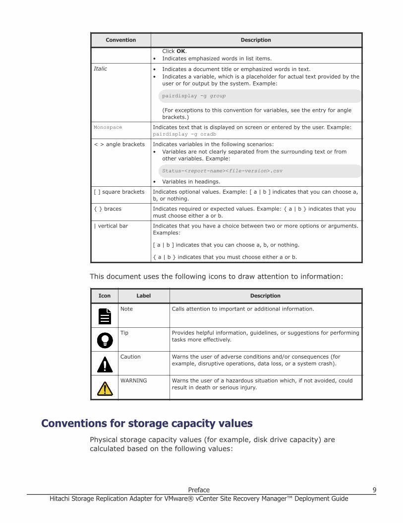
Document conventionsThis document uses the following typographic conventions:
Convention Description
Bold • Indicates text in a window, including window titles, menus, menu options,buttons, fields, and labels. Example:
8 PrefaceHitachi Storage Replication Adapter for VMware® vCenter Site Recovery Manager™ Deployment Guide
Convention Description
Click OK.• Indicates emphasized words in list items.
Italic • Indicates a document title or emphasized words in text.• Indicates a variable, which is a placeholder for actual text provided by the
user or for output by the system. Example:
pairdisplay -g group
(For exceptions to this convention for variables, see the entry for anglebrackets.)
Monospace Indicates text that is displayed on screen or entered by the user. Example:pairdisplay -g oradb
< > angle brackets Indicates variables in the following scenarios:• Variables are not clearly separated from the surrounding text or from
other variables. Example:
Status-<report-name><file-version>.csv
• Variables in headings.
[ ] square brackets Indicates optional values. Example: [ a | b ] indicates that you can choose a,b, or nothing.
{ } braces Indicates required or expected values. Example: { a | b } indicates that youmust choose either a or b.
| vertical bar Indicates that you have a choice between two or more options or arguments.Examples:
[ a | b ] indicates that you can choose a, b, or nothing.
{ a | b } indicates that you must choose either a or b.
This document uses the following icons to draw attention to information:
Icon Label Description
Note Calls attention to important or additional information.
Tip Provides helpful information, guidelines, or suggestions for performingtasks more effectively.
Caution Warns the user of adverse conditions and/or consequences (forexample, disruptive operations, data loss, or a system crash).
WARNING Warns the user of a hazardous situation which, if not avoided, couldresult in death or serious injury.
Conventions for storage capacity valuesPhysical storage capacity values (for example, disk drive capacity) arecalculated based on the following values:
Preface 9Hitachi Storage Replication Adapter for VMware® vCenter Site Recovery Manager™ Deployment Guide

Physical capacity unit Value
1 kilobyte (KB) 1,000 (10 3) bytes
1 megabyte (MB) 1,000 KB or 1,0002 bytes
1 gigabyte (GB) 1,000 MB or 1,0003 bytes
1 terabyte (TB) 1,000 GB or 1,0004 bytes
1 petabyte (PB) 1,000 TB or 1,0005 bytes
1 exabyte (EB) 1,000 PB or 1,0006 bytes
Logical capacity values (for example, logical device capacity, cache memorycapacity) are calculated based on the following values:
Logical capacity unit Value
1 block 512 bytes
1 cylinder Mainframe: 870 KB
Open-systems:• OPEN-V: 960 KB• Others: 720 KB
1 KB 1,024 (210) bytes
1 MB 1,024 KB or 1,0242 bytes
1 GB 1,024 MB or 1,0243 bytes
1 TB 1,024 GB or 1,0244 bytes
1 PB 1,024 TB or 1,0245 bytes
1 EB 1,024 PB or 1,0246 bytes
Accessing product documentationProduct user documentation is available on Hitachi Vantara Support Connect: https://knowledge.hitachivantara.com/Documents. Check this site for themost current documentation, including important updates that may havebeen made after the release of the product.
Getting helpHitachi Vantara Support Connect is the destination for technical support ofproducts and solutions sold by Hitachi Vantara. To contact technical support,log on to Hitachi Vantara Support Connect for contact information: https://support.hitachivantara.com/en_us/contact-us.html.
Hitachi Vantara Community is a global online community for Hitachi Vantaracustomers, partners, independent software vendors, employees, andprospects. It is the destination to get answers, discover insights, and make
10 PrefaceHitachi Storage Replication Adapter for VMware® vCenter Site Recovery Manager™ Deployment Guide
connections. Join the conversation today! Go to community.hitachivantara.com, register, and complete your profile.
CommentsPlease send us your comments on this document to [email protected]. Include the document title and number,including the revision level (for example, -07), and refer to specific sectionsand paragraphs whenever possible. All comments become the property ofHitachi Vantara Corporation.
Thank you!
Preface 11Hitachi Storage Replication Adapter for VMware® vCenter Site Recovery Manager™ Deployment Guide

12 PrefaceHitachi Storage Replication Adapter for VMware® vCenter Site Recovery Manager™ Deployment Guide
1Overview
This chapter describes Hitachi Storage Replication Adapter (SRA) 2.x and theVMware® vCenter Site Recovery Manager™ 5.x/6.x disaster recoverysolution when used with Hitachi storage.
The following topics are discussed:
□ About Hitachi Storage Replication Adapter and Site Recovery Manager
□ Command Control Interface (CCI)
□ How the VMware® vCenter SRM™/SRA solution works
Overview 13Hitachi Storage Replication Adapter for VMware® vCenter Site Recovery Manager™ Deployment Guide

About Hitachi Storage Replication Adapter and SiteRecovery Manager
VMware® vCenter Site Recovery Manager™ 5.x/6.x (VMware® vCenterSRM™) is a VMware application that automates the disaster recovery processusing storage-based replication.
Hitachi Storage Replication Adapter (SRA) is an interface that integratesHitachi storage systems and replication software with VMware® vCenterSRM™ processes.
Used together, VMware® vCenter SRM™ and Hitachi storage and softwareprovide an automated and seamless disaster recovery solution within theVMware vCenter infrastructure.
VMware vCenter infrastructureThe VMware® vCenter SRM™/Hitachi SRA solution on the VMware sideconsists of the following:• VMware vSphere, the virtualization platform with data center
infrastructure. vSphere consists of:○ VMware ESX/ESXi host, which is a virtualization platform that provides a
data center infrastructure in which many virtual machines sharehardware resources from a single physical machine. The ESX/ESXi hostloads directly on a physical server.
○ vCenter Server, which provides management of one or multiple vSphereenvironments.
These vSphere elements are used on the protected and recovery sites.
• VMware® vCenter SRM™, which provides a disaster recovery solution thatreduces planned and unplanned downtime of the vSphere infrastructure.
Hitachi storage and replication software productsThe Hitachi Storage Replication Adapter (SRA) links VMware® vCenter SRM™
and Hitachi storage and replication software. The SRA/VMware® vCenterSRM™ solution supports:• Hitachi Virtual Storage Platform G1x00 (VSP G1x00)• Hitachi Virtual Storage Platform F1500 (VSP F1500)• Hitachi Virtual Storage Platform G200, G400, G600, G800 (VSP Gx00
models)• Hitachi Virtual Storage Platform F400, F600, F800 (VSP Fx00 models)• Hitachi Virtual Storage Platform (VSP)• Hitachi Unified Storage (HUS)
14 OverviewHitachi Storage Replication Adapter for VMware® vCenter Site Recovery Manager™ Deployment Guide

• Hitachi Unified Storage VM (HUS VM)• Hitachi Universal Storage Platform V/VM (USP V/VM)• Hitachi Adaptable Modular Storage (AMS)
Note: A separate Hitachi NAS SRA is available for environments using NFSdatastores. View related documentation by clicking: https://www.hitachivantara.com/en-us/pdf/white-paper/hitachi-storage-replication-adapter-for-hitachi-nas-platform.pdf.
Hitachi remote and in-system replication are key features of the solution.Remote replication is used to backup protected site data at the recovery sitein a remote location. In-system replication is used on the remote site tocreate a clone volume for testing the VMware® vCenter SRM™-SRA solution.
The following remote replication products are supported:• Hitachi Universal Replicator, which provides long-distance asynchronous
replication across any distance without significant impact on hostperformance.
• Hitachi TrueCopy Remote Replication, which provides synchronous remotereplication.
• Global-active device (GAD), which provides synchronous remotereplication.
• Hitachi TrueCopy Extended Distance (TCE), which provides asynchronousremote replication. TCE is used with HUS.
The following in-system replication products are supported for creating aclone of the recovery site volume for testing.• Hitachi ShadowImage® (SI), which creates RAID-protected duplicate
volumes within the storage system. With ShadowImage, you create aclone of the remote backup volume in the remote storage system.
• Hitachi Thin Image (HTI), which creates a virtual backup of a productionvolume from a point in time “snapshot”.
Hitachi users manage storage and data replication operations using theCommand Control Interface (CCI) command line interface (CLI) softwareproduct.
The following figure shows basic VMware® vCenter SRM™/SRA components.
Overview 15Hitachi Storage Replication Adapter for VMware® vCenter Site Recovery Manager™ Deployment Guide

Figure 1 VMware® vCenter SRM™ and Hitachi components
Command Control Interface (CCI)Hitachi's remote and in-system replication software require CCI to managethe pairs. The adapter plug-in links CCI with Site Recovery Manager.
There are two CCI components:• Command devices, which reside on the storage systems. CCI uses the
command device as the interface to the storage system from the host. Thecommand device accepts commands from the host and executes them onthe storage system. The command device is a dedicated logical volume.
• Hitachi Open Remote Copy Manager (HORCM), which resides on the CCIserver. HORCM operates as a daemon process. When activated, HORCMrefers to CCI configuration definition files, also located on the server. TheHORCM instance communicates with the storage system and remoteservers.HORCM definition files describe the storage systems, pair volumes, anddata paths. When a user issues a command, CCI uses the information inthe HORCM files to identify which volumes are the targets of thecommand.Two HORCM files are needed for each pair. One file describes the primaryvolumes (P-VOLs), which are also referred to as “protected volumes”, andthe other describes the secondary volumes (S-VOLs), which are alsoreferred to as “recovery volumes”.
16 OverviewHitachi Storage Replication Adapter for VMware® vCenter Site Recovery Manager™ Deployment Guide

Figure 1 VMware vCenter SRM and Hitachi components on page 16 shows atwo-server, two-HORCM instance setup with optional in-system test copy.
How the VMware® vCenter SRM™/SRA solution worksVMware® vCenter SRM™ coordinates process with Hitachi storage andreplication so that in a recovery condition, the virtual machines at theprotected site are shut down and the replicated virtual machines are poweredup.
Recovery is guided by a recovery plan in which you have specified an orderthat virtual machines are to be started up.
After a recovery is performed, the running virtual machines are no longerprotected. VMware® vCenter SRM™ provides a reprotect operation, whichruns after the original protected site is back up. Reprotect activates CCIoperations that reverse-synchronize data in the storage systems fromrecovery site to protected site.
Finally, VMware® vCenter SRM™-supported failback (VSP G1000, VSPG1500, VSP F1500, VSP Gx00 models, VSP Fx00 models, VSP, HUS VM, andUSP V/VM only) and reprotect operations allow you to restore protection backto the original configuration, with data flow from the protected site to therecovery site.
VMware® vCenter SRM™ lets you test recovery plans using an in-systemcopy of the replicated data without disrupting ongoing operations at eithersite.
Overview 17Hitachi Storage Replication Adapter for VMware® vCenter Site Recovery Manager™ Deployment Guide

18 OverviewHitachi Storage Replication Adapter for VMware® vCenter Site Recovery Manager™ Deployment Guide

2Requirements, planning, and
prerequisitesYou share responsibilities for planning and deploying SRA 2.x with the HitachiVantara account team, which will assist you as needed throughout theprocess. The account team coordinates Hitachi Vantara resources to ensure asuccessful installation and deployment. Before you begin planning, it mightbe useful to review the deployment workflow in Deployment on page 31.
This chapter provides requirements and planning information in the followingtopics:
□ Requirements
□ SRA/VMware® vCenter SRM™/CCI location options
□ Test options
□ Configurations with protected and recovery VMs on the same site
□ Consistency groups and VM failover groups
□ Consistency groups and same-time split operations
□ About the TrueCopy fence level “Never”
□ Prerequisites for global-active device configuration
□ AMS 2000 host group options
Requirements, planning, and prerequisites 19Hitachi Storage Replication Adapter for VMware® vCenter Site Recovery Manager™ Deployment Guide

RequirementsThis section lists hardware and software requirements.
Table 1 Required hardware and software
Item Description
Hitachi Storage ReplicationAdapter version
• SRA 02.01.04—VMware® vCenter SRM™ 5.x/6.0/6.1.○ Supports SSH connections○ Supports VMware® vCenter SRM™ on one array in loopback
mode, for testing only in non-production environments○ Requires HITACHI_RMHTCSRA_X64-02.01.4.exe
• SRA 02.02.00—VMware® vCenter SRM™ 6.1 or later.○ Supports CCI version 01-36-03/03 or later○ Supports global-active device (GAD).○ Requires HITACHI_RMHTCSRA_X64-02.02.00.exe
• SRA 02.03.00—VMware® vCenter SRM™ 6.5 or later.○ Supports CCI version 01-36-03/03 or later○ Supports iSCSI for VSP G1000, VSP G1500, VSP F1500, VSP
Gx00 models, VSP Fx00 models, and HUS.○ Requires HITACHI_RMHTCSRA_X64-02.03.00.exe
• SRA 02.03.01—VMware® vCenter SRM™ 6.1 or later.○ Supports CCI version 01-36-03/03 or later.○ Supports global-active device (GAD).○ Supports iSCSI for VSP G1000, VSP G1500, VSP F1500, VSP
Gx00 models, VSP Fx00 models, and HUS.○ Requires HITACHI_RMHTCSRA_X64-02.03.01.exe
Supported Hitachi storagesystems and microcode levels
• SRA 02.01.04—VMware® vCenter SRM™ 5.x/6.0/6.1.○ VSP Gx00 models firmware 83-00-xx or later○ VSP Fx00 models firmware 83-02-xx or later○ HUS VM microcode 73-01-01 or later○ VSP G1000 microcode 80-01-01 or later○ VSP microcode 70-05-xx or later○ USP V/VM microcode 60-07-xx or later○ TagmaStore USP: 50-09-xx or later TagmaStore NSC:
50-09-xx or later○ HUS firmware 0930/A-H or later○ AMS firmware 08C3/E or later
• SRA 02.02.00—VMware® vCenter SRM™ 6.1 or later.○ VSP Gx00 models firmware 83-01-01 or later
When GAD is used: 83-04-01 or later○ VSP Fx00 models firmware 83-02-xx or later
When GAD is used: 83-04-01 or later○ HUS VM microcode 73-01-01 or later○ VSP G1000 microcode 80-01-01 or later
When GAD is used: 80-04-02 or later○ VSP G1500, VSP F1500 microcode 80-05-01 or later
When GAD is used: 80-05-01 or later○ VSP microcode 70-05-xx or later○ USP V/VM microcode 60-07-xx or later
20 Requirements, planning, and prerequisitesHitachi Storage Replication Adapter for VMware® vCenter Site Recovery Manager™ Deployment Guide

Item Description
• SRA 02.03.00—VMware® vCenter SRM™ 6.5 or later.○ VSP Gx00 models firmware 83-01-01 or later○ VSP Fx00 models firmware 83-02-xx or later○ HUS VM microcode 73-01-01 or later○ VSP G1000 microcode 80-01-01 or later○ VSP G1500, VSP F1500 microcode 80-05-01 or later○ VSP microcode 70-05-xx or later○ USP V/VM microcode 60-07-xx or later○ HUS firmware 0930/A-H or later
• SRA 02.03.01—VMware® vCenter SRM™ 6.1 or later.○ VSP Gx00 models firmware 83-01-01 or later.
When GAD is used: 83-04-01 or later.○ VSP Fx00 models firmware 83-02-xx or later
When GAD is used: 83-04-01 or later○ HUS VM microcode 73-01-01 or later○ VSP G1000 microcode 80-01-01 or later
When GAD is used: 80-04-02 or later○ VSP G1500, VSP F1500 microcode 80-05-01 or later
When GAD is used: 80-05-01 or later○ VSP microcode 70-05-xx or later○ USP V/VM microcode 60-07-xx or later○ HUS firmware 0930/A-H or later
Supported operating systems • SRA 2.1 or earlier: Windows Server 2003 or laterSRA 2.2, 2.3: Windows Server 2008 or later
• Linux• Solaris• Solaris/x86• HP-UX• AIX®
VMware infrastructure Environments:• Site Recovery Manager (SRM) (can also be installed on a
physical server)• Use SRM 5.x, SRM 6.0, SRM 6.1, and SRM 6.5
Protected site:• VMware vCenter Server• ESX/ESXi host• Datastore on the ESX/ESXi host
Recovery site:• VMware vCenter Server• ESX/ESXi host• Datastores: You do not need to create datastores in the
recovery site. However, two volumes with the same capacity asthe datastore of the primary ESX/ESXi host are required. Thevolumes must be mapped to the recovery ESX/ESXi host onlywhen TC or UR is used. Do not install datastores on thesevolumes. In the case of GAD, secondary volumes of GAD pairsare recognized as datastores in the recovery site.
CCI • Version 01-27-03/04 or later: Supported for VSP, HUS VM, USPV/VM, TagmaStore USP/TagmaStore NSC.
• Version 01-30-03/03 or later: Supported for VSP G1000, VSP,HUS VM, USP V/VM, TagmaStore USP/TagmaStore NSC.
Requirements, planning, and prerequisites 21Hitachi Storage Replication Adapter for VMware® vCenter Site Recovery Manager™ Deployment Guide

Item Description
• Version 01-33-03/06 or later: Supported for the Hitachi storagesystems listed in “Supported Hitachi storage systems andmicrocode levels”.
• CCI must be installed on protected and recovery sites onWindows or UNIX systems. If Windows is used, CCI andVMware® vCenter SRM™ must be installed on the same server.For more information, see SRA/VMware® vCenter SRM™/CCIlocation options on page 22.
Remote replication • When using VSP G1x00, VSP F1500, VSP, VSP Gx00 models,VSP Fx00 models, HUS VM, and USP V/VM, use one of thefollowing:○ TrueCopy Remote Replication○ Universal Replicator○ Global-active device (VSP G1x00, VSP F1500, VSP Gx00
models, VSP Fx00 models)
• When using HUS, use one of the following:○ TrueCopy Remote Replication○ TrueCopy Extended Distance
• When using AMS 2000 Family, use TrueCopy RemoteReplication.
In-system replication licensekey
ShadowImage, Thin Image, or Copy-on-Write Snapshot. Used fortesting.• Optional for VSP G1x00, VSP F1500, VSP Gx00 models, VSP
Fx00 models, VSP, USP V/VM, and HUS testing• Required for AMS testing
SRA/VMware® vCenter SRM™/CCI location optionsThe VMware® vCenter SRM™ array manager configuration for SRA 2.x variesdepending on the location of CCI.• If the Windows version of CCI is used, CCI must be installed on both
protection and recovery sites. This means that CCI, VMware® vCenterSRM™, and SRA 2.x must be installed on the same servers. SRA 2.x willcommunicate locally with CCI.
• If the UNIX version of CCI is used, VMware® vCenter SRM™ arraymanagers can be configured using telnet or SSH* to remotelycommunicate with CCI instances. VMware® vCenter SRM™ and SRA mustbe installed on the same server, and CCI can run on separate (remote)UNIX hosts. This allows you to run a centralized UNIX CCI host instead ofrunning UNIX CCI hosts for each site (protection and recovery). HitachiVantara does not recommend running a centralized CCI host forredundancy reasons.
* SRA 2.3 and later versions support only SSH and does not support telnet.
22 Requirements, planning, and prerequisitesHitachi Storage Replication Adapter for VMware® vCenter Site Recovery Manager™ Deployment Guide

Test optionsSRA/VMware® vCenter SRM™ recovery takes place automatically. To ensurethat recovery occurs as expected, the recovery processes must be testedmanually.• For VSP G1000, VSP G1500, VSP F1500, VSP Gx00 models, VSP Fx00
models, VSP, USP V/VM, and HUS, testing is done using either a copy ofthe S-VOL (recommended) or the remote S-VOL.Note: The remote S-VOL for GAD cannot be used.
• For AMS, testing can only be done using a copy of the S-VOL.
Using the S-VOL for testingIf your storage system is a VSP G1000, VSP G1500, VSP F1500, VSP Gx00models, VSP Fx00 models, VSP, USP V/VM, or HUS, VMware® vCenter SRM™can use the S-VOL on the remote site for test failover.
However, note the following important restrictions:• Testing with the S-VOL disrupts replication from the primary to the
secondary volumes.You can avoid disruption to replication if you test during planned outages.
• The S-VOL is not available for an actual failover should the need arise.
• After testing, the pair is resynchronized with data that was stored in abitmap. The updates are out of order, rendering the S-VOL unavailable foran actual failover should the need arise, until resynchronization iscompleted.
Required configuration for testing with S-VOLThe TrueCopy or Universal Replicator pair must be split in order to test usingthe S-VOL. The following figure shows the VMware® vCenter SRM™configuration during test failover using the S-VOL.
To enable SRA to allow the split and to test with the S-VOL, you must set twoenvironment variables on the host. For instructions, see Configuring SRA fortesting on page 46.
Requirements, planning, and prerequisites 23Hitachi Storage Replication Adapter for VMware® vCenter Site Recovery Manager™ Deployment Guide

Using a copy of the S-VOL for testingYou can test failover with no disruption to replication between primarysecondary systems using a point-in-time copy of the remote system S-VOL.
During test failover, the remote replication pair remains in PAIR status, andtherefore protection continues uninterrupted.
ShadowImage, Thin Image, and Copy-on-Write Snapshot are Hitachi in-system replication products available for creating copies of the S-VOL on theremote site. These products are supported for the SRA/VMware® vCenterSRM™ solution on the VSP G1000, VSP G1500, VSP F1500, VSP Gx00models, VSP Fx00 models, VSP, USP V/VM, HUS, and AMS storage systems.
Required configuration for testing with a copy of S-VOLThe in-system S-VOL must be assigned an MU#. By default, SRA looks forMU#0 to test with. When you use MU#0, then no further configuration isnecessary for testing.
If you specify a different MU#, then you must set environment variables onthe host to enable SRA to use it. For instructions, see Configuring SRA fortesting on page 46.
The following figure shows an example of test failover using a ShadowImagecopy.
ShadowImage port requirementThe ShadowImage S-VOL must be presented on the same Fibre Channel oriSCSI port as the ShadowImage P-VOL.
Otherwise the UUID on the datastore changes. ESX/ESXi cannot attach theUUID to the shadow virtual machine for test failover unless the UUIDmatches.
24 Requirements, planning, and prerequisitesHitachi Storage Replication Adapter for VMware® vCenter Site Recovery Manager™ Deployment Guide

Configurations with protected and recovery VMs on thesame site
SRA/VMware® vCenter SRM™ supports a configuration in which bothprotected and recovery VMs are present on the local and remote sites, thusproviding protection for each site. For more information, see Configurationswith both sites active on page 83.
Consistency groups and VM failover groupsCCI consistency groups are used to perform a single pair operation on agrouping of pairs with similar or the same kind of data. This ensures that allthe pairs are managed in a consistent status. Consistency groups are definedin the HORCM definition files and are assigned when you create the pairs.
This is done before setting up your protection group. All virtual machines in aprotection group store their files within the same datastore group, and allfailover together.
Consistency groups must be aligned with the VM failover groups. This meansthat the LUNs associated with VMs that will be failed over as a group must beincluded in a single consistency group. Failure to do this can cause therecovery plan to fail.
Also, adding LUNs that are associated with different VMs or physical hosts toa consistency group not associated with those VMs or hosts can cause anoutage on these additional VMs or hosts.
Consistency groups and same-time split operationsP-VOLs in the same CCI consistency group are split at the same time. Inaddition, you can specify a time that a split operation is to be performed onthe consistency group.
This CCI operation is called At-Time Split. Data consistency is guaranteedacross the consistency group when you perform the At-Time Split operation.
The At-Time Split can only be performed on the pairs in a CCI consistencygroup.
Hitachi recommends assigning P-VOLs in a protected group to the same CCIconsistency group, and warns against placing a protected group’s P-VOLs inmultiple consistency groups.
See the TrueCopy, Universal Replicator, or global-active device user guide foryour storage system for information about using consistency groups and theAt-Time Split operation.
Requirements, planning, and prerequisites 25Hitachi Storage Replication Adapter for VMware® vCenter Site Recovery Manager™ Deployment Guide

About the TrueCopy fence level “Never”Using “Never” for the fence level for TrueCopy pairs causes the internalhorctakeover to fail; the command returns with EX_VOLCUR.
This occurs because “Never” cannot completely guarantee data consistency.
However, the VMware® vCenter SRM™/VMware goal of Failover/ testFailoveris booting the VM’s. This makes the fence level “Never” acceptable despitethe horctakeover return of EX_VOLCUR.
If you use “Never”, remember that the recovery will be on APP (SQL/Exchange/Oracle/..).
Prerequisites for global-active device configurationWhen you use global-active device (GAD) for remote replication, each ESXihost must be connected to both primary and secondary volumes as shown inthe figure.
The connections are required because I/O to primary volumes might bemomentarily blocked during planned migration, which results in failure ofplanned migration.
The connection must be managed by multipath software so that I/O fromeach ESXi host to the primary (or secondary) volumes can be transparentlyrerouted to the secondary (or primary) volumes in the case when the I/O tothe primary (or secondary) volumes is blocked, as shown in Figure 3 I/Orerouting by multipath software on page 27.
Figure 2 Connections when using GAD
26 Requirements, planning, and prerequisitesHitachi Storage Replication Adapter for VMware® vCenter Site Recovery Manager™ Deployment Guide

Figure 3 I/O rerouting by multipath software
Note the following when using GAD:• Rerouting caused by I/O blockade on primary volumes shown in
Figure 3 I/O rerouting by multipath software on page 27 might increaseI/O latency. If you run latency-sensitive application software in virtualmachines, it is recommended that you manually reroute I/O to secondaryvolumes before running planned migration.
• Latency of I/O from each ESXi in the protected site to the storage systemin the recovery site can be larger than that of I/O from each ESXi in theprotected site to the storage system in the protected site.For example, the latency is generally larger when the recovery site islocated far away from the protected site. If the latency is larger in yourenvironment, reroute I/O back to the original volumes after plannedmigration has completed.
• Do not disconnect the connection by deleting LU.
• When all of the following conditions are satisfied, you cannot run plannedmigration nor disaster recovery:○ The I/O mode of secondary volumes in the recovery site is “Block”.○ The connections between each ESXi host in the recovery site and the
storage system in the protected site are not active.
• If you run disaster recovery when all of the following conditions aresatisfied, virtual machines might not be powered on in the recovery siteafter disaster recovery. In this case, shut down the virtual machines in theprotected site or disconnect the connection between each ESXi in the
Requirements, planning, and prerequisites 27Hitachi Storage Replication Adapter for VMware® vCenter Site Recovery Manager™ Deployment Guide
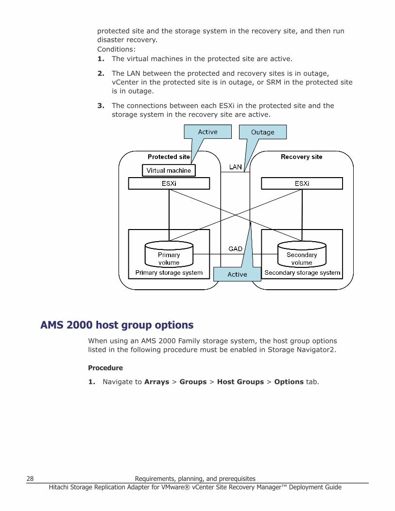
protected site and the storage system in the recovery site, and then rundisaster recovery.Conditions:1. The virtual machines in the protected site are active.
2. The LAN between the protected and recovery sites is in outage,vCenter in the protected site is in outage, or SRM in the protected siteis in outage.
3. The connections between each ESXi in the protected site and thestorage system in the recovery site are active.
AMS 2000 host group optionsWhen using an AMS 2000 Family storage system, the host group optionslisted in the following procedure must be enabled in Storage Navigator2.
Procedure
1. Navigate to Arrays > Groups > Host Groups > Options tab.
28 Requirements, planning, and prerequisitesHitachi Storage Replication Adapter for VMware® vCenter Site Recovery Manager™ Deployment Guide

2. Ensure that the following are specified or not specified as listed:• Platform: VMware
• Middleware: Not specified
• Common Setting: Standard Mode
Requirements, planning, and prerequisites 29Hitachi Storage Replication Adapter for VMware® vCenter Site Recovery Manager™ Deployment Guide

• Additional Setting: Enable only Unique Extended COPY Mode andUnique Write Same Mode.
30 Requirements, planning, and prerequisitesHitachi Storage Replication Adapter for VMware® vCenter Site Recovery Manager™ Deployment Guide

3Deployment
This chapter provides instructions for deploying Hitachi Storage ReplicationAdapter 2.0. The following topics are discussed:
□ Deployment workflow
□ Installing CCI
□ Creating and configuring a command device
□ Setting up HORCM configuration definition files
□ Starting HORCM instances, creating pairs
□ Setting environment variables
□ Configuring SRA for testing
□ SRA installation
□ Configuring SRM™ to communicate with RMSRA20 (SRM 5.x or earlier)
□ Configuring SRM to communicate with RMSRA20 (SRM 6.0 or later)
□ Performing reprotect and failback
Deployment 31Hitachi Storage Replication Adapter for VMware® vCenter Site Recovery Manager™ Deployment Guide

Deployment workflowThe following workflow shows a basic order for setting up the SRA/ VMware®vCenter SRM™ solution.
When a task is outside the scope of this document, a reference is provided tothe appropriate documentation.
Table 2 Workflow for deploying
Task How to
1. Review requirements and planningconsiderations.
See Requirements on page 20.
2. Configure the storage area network See the Hitachi whitepaper, Deploying VMware SiteRecovery Manager 5.0 with VMware vSphere 5.0 onHitachi Virtual Storage Platform, Implementation Guide(3/2012).
3. Configure Hitachi remote replicationusing Storage Navigator. Includesstorage, pair volume, port, logicalpath, and data path setup.
See the appropriate TrueCopy, Universal Replicator, orglobal-active device user guide for instructions.
4. (Optional). Configure in-systemreplication for testing SRA/VMware®vCenter SRM™.
See the appropriate ShadowImage or Thin Image userguide for information.
5. Install Command Control Interface(CCI) to manage storage replication.
See Installing CCI on page 33.
6. Create and map a command device. See Creating and configuring a command device onpage 33.
7. Set up CCI HORCM files with pairand path information.
See Setting up HORCM configuration definition files onpage 36.
8. Create pairs. See Starting HORCM instances, creating pairs onpage 41.
9. Ensure VMware® vCenter SRM™2013 and VMware® vCenter SRM™databases are installed.
See VMware vCenter Site Recovery Managerdocumentation.
10. Install SRA 2.x. See SRA installation on page 47.
11. Connect protected and recoverysites.
See VMware vCenter Site Recovery Managerdocumentation.
12. Configure SRA in Site RecoveryManager.
See Configuring SRM™ to communicate with RMSRA20(SRM 5.x or earlier) on page 50 or Configuring SRM tocommunicate with RMSRA20 (SRM 6.0 or later) onpage 56.
13. Set up inventory mappings,protection group, recovery plan,perform test recovery.
See VMware vCenter Site Recovery Managerdocumentation.
Note: In a GAD configuration, the protection groups arecreated with Storage Policy base.
32 DeploymentHitachi Storage Replication Adapter for VMware® vCenter Site Recovery Manager™ Deployment Guide
Installing CCICommand Control Interface (CCI) is a collection of executable files that youuse to manage replication and data protection operations.
You run CCI commands from a command line or use scripts consisting of aseries of commands that automate several related processes.
• SRA 2.0 and SRA 2.1 require CCI version 01-24-03/13 or later.
• SRA 2.2 and SRA 2.3 require CCI version 01-36-03/03 or later.
For installation and upgrade instructions, see the Hitachi Command ControlInterface Installation and Configuration Guide.
If CCI is installed on the VMware® vCenter SRM™ host, Hitachi Vantararecommends that you run HORCM as a service. (HORCM is described in Setting up HORCM configuration definition files on page 36.)
Creating and configuring a command deviceA command device (CMD) is a dedicated logical device on the storage systemused by CCI for communications between the host and the storage system.
The CMD allows the CCI software to send commands using in-band protocolto the storage system. One CMD is required by CCI per storage system.
Do not use the CMD to store user data. Define and configure it as a rawdevice with no file system and no mount operation.
In the following procedure, you will create an LDEV, assign it as a CMD in thestorage system, map it to a physical server or Windows virtual machine onthe ESXi host—where VMware® vCenter SRM™ and CCI are installed, andconfigure it.
Procedure
1. In the Storage Navigator Explorer pane, click Storage Systems,expand the target storage system, and then click Logical Devices.
Deployment 33Hitachi Storage Replication Adapter for VMware® vCenter Site Recovery Manager™ Deployment Guide

2. On the LDEVs tab-lower right, click Create LDEVs to create a newvolume to be used as a command device.
3. Proceed through the Create LDEVs wizard, keeping the following inmind:• The CMD LDEV can be from a regular parity group or an HDP pool.
• The CMD LDEV can be small, but with a minimum of 47MB.
4. On the LDEVs tab, select the newly created LDEV, then click MoreActions > Edit Command Devices.
34 DeploymentHitachi Storage Replication Adapter for VMware® vCenter Site Recovery Manager™ Deployment Guide

5. In the Edit Command Devices wizard, select Enable for CommandDevice. Leave the Command Device Attributes disabled.
6. Click Finish.7. Now map the CMD volume to the CCI server (virtual or physical). If the
CCI server is a virtual server, map the CMD to the ESX/ESXi host wherethe VM resides.
8. From the VMware vSphere client, add the CMD LDEV to the VMware®vCenter SRM™ virtual machine as a physical RDM virtual disk.
9. Configure the command device in the guest operating system as follows:1. In Microsoft Windows 2008, from the Server Manager menu, point to
Storage and click Disk Management.
2. Right-click the RDM disk and click Online.
3. Right-click the RDM disk and click Initialize Disk.
4. Click MBR (Master Boot Record) as the partition style.
Deployment 35Hitachi Storage Replication Adapter for VMware® vCenter Site Recovery Manager™ Deployment Guide

10. Present a CMD volume from the primary storage system to the primaryESX/ESXi server, and another CMD volume from the secondary storagesystem to the recovery ESX/ESXi server.
Setting up HORCM configuration definition filesYou will need two HORCM configuration definition files to define the pairrelationship: one file describes the primary volumes (P-VOLs), the other filedescribes the secondary volumes (S-VOLs).
A third HORCM configuration definition file is required if you use aShadowImage, Thin Image, or Copy-on-Write Snapshot copy of the remotesite S-VOL for testing.
Figure 1 VMware vCenter SRM and Hitachi components on page 16 providesa configuration example that shows the HORCM configuration definition fileson the local and remote servers.
Editing HORCM.conf filesHORCM configuration definition files are used to identify the target volumesof a CCI command.
You can copy and modify the HORCM files included with the remotereplication bundle. You will identify your pair volumes and data paths in thesefiles.
Note the following when editing HORCM.conf files:• Use a text editor to edit HORCM files. Default HORCM.conf files are located
in:○ Hitachi TrueCopy Remote Replication bundle files
○ Hitachi Universal Replicator files
○ (Optional) Hitachi ShadowImage Heterogeneous Replication files
• Save a copy of the HORCM.conf files on the local and remote CCI serversin the C:\Windows folder.
• HORCM files must be named horcm#.conf, where “#” represents theHORCM instance.○ The instance on the primary site is usually 0. In this case, the HORCM
file on the primary site would be named, horcm0.conf.
○ The # of the secondary instance must be the primary instance numberplus 1. Thus, if the primary instance is 0, the HORCM file on thesecondary site would be named, horcm1.conf.
○ Likewise, the # of ShadowImage, Thin Image, or Copy-on-WriteSnapshot S-VOL instance must be the secondary instance number plus
36 DeploymentHitachi Storage Replication Adapter for VMware® vCenter Site Recovery Manager™ Deployment Guide

1. Thus, if the secondary instance is 1, the HORCM file for the in-systemS-VOL would be named horcm2.conf.
○ It is best practice to name devices the same as the datastore containedin the LU. The following figure shows example device naming schemes.
• HORCM_LDEVG with SRM and the Hitachi SRA 2.1.4 and later issupported. The HORCM_LDEVG parameter defines the device groupinformation that the CCI instance reads. The following values are defined:Copy_Group, ldev_group, Serial#. For example:
HORCM_LDEVG#Copy_Group ldev_group Serial#ora grp1 64034
For details, see the Command Control Interface User and Reference Guide(MK-90RD7010).
Deployment 37Hitachi Storage Replication Adapter for VMware® vCenter Site Recovery Manager™ Deployment Guide

HORCM examples are provided in the following sections for the primary site,secondary site, and an optional secondary-site test pair.
Primary HORCM fileExample HORCM0.conf for primary site remote replication pair on page 39shows an example of the HORCM file for the primary storage system.
38 DeploymentHitachi Storage Replication Adapter for VMware® vCenter Site Recovery Manager™ Deployment Guide

Example HORCM0.conf for primary site remote replication pair
HORCM_MON#ip_address service poll(10ms) timeout(10ms)172.17.46.38 horcm0 1000 3000
HORCM_CMD#dev_name\\.\CMD-64015
HORCM_LDEV#dev_group dev_name Serial# CU:LDEV(LDEV#) MU#TC_UR_SRM1 01A_01B 64015 00:1A
HORCM_INST#dev_group ip_address serviceTC_UR_SRM1 172.17.46.39 horcm1
The configuration files consist of the following sections:• HORCM_MON — Information for monitoring the HORCM instance.
Includes the IP address of the primary server, HORCM instance or service,polling interval for monitoring paired volumes, and timeout period forcommunication with the remote server.
• HORCM_CMD — Command device from the protected storage system.Replace the number with the serial number of the primary storage system.
• HORCM_LDEV — Consists of the following:○ #dev_group is the group name for the pairs, which allows you to run a
pair operation against the pairs in the group.○ dev_name is the pair name (example uses P-VOL_S-VOL).○ Serial# is the storage system’s serial number.○ CU:LDEV(LDEV#) is the LDEV ID of the P-VOL.○ MU# is the mirror unit number. Use MU#0-2 for ShadowImage, Thin
Image, and Copy-on-Write Snapshot. You do not need to specify MU#for TC, UR, and GAD. If you want to specify MU# for TC, UR, and GAD,use MU#h0 for TC and MU#h0-h3 for UR and GAD.
• HORCM_INST — Consists of the following:○ #dev_group is the group name for the pairs.○ ip address is the network address of the remote server.○ service is the remote HORCM instance.
Secondary HORCM fileExample HORCM1.conf for secondary site remote replication pair with in-system test pair on page 40 shows an example of the HORCM file for thesecondary storage system.
Deployment 39Hitachi Storage Replication Adapter for VMware® vCenter Site Recovery Manager™ Deployment Guide
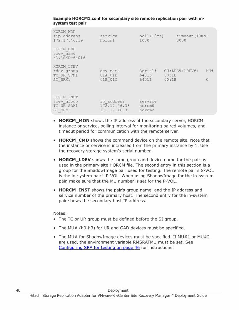
Example HORCM1.conf for secondary site remote replication pair with in-system test pair
HORCM_MON#ip_address service poll(10ms) timeout(10ms)172.17.46.39 horcm1 1000 3000
HORCM_CMD#dev_name\\.\CMD-64016
HORCM_LDEV#dev_group dev_name Serial# CU:LDEV(LDEV#) MU#TC_UR_SRM1 01A_01B 64016 00:1BSI_SRM1 01B_01C 64016 00:1B 0
HORCM_INST#dev_group ip_address serviceTC_UR_SRM1 172.17.46.38 horcm0SI_SRM1 172.17.46.39 horcm2
• HORCM_MON shows the IP address of the secondary server, HORCMinstance or service, polling interval for monitoring paired volumes, andtimeout period for communication with the remote server.
• HORCM_CMD shows the command device on the remote site. Note thatthe instance or service is increased from the primary instance by 1. Usethe recovery storage system’s serial number.
• HORCM_LDEV shows the same group and device name for the pair asused in the primary site HORCM file. The second entry in this section is agroup for the ShadowImage pair used for testing. The remote pair’s S-VOLis the in-system pair’s P-VOL. When using ShadowImage for the in-systempair, make sure that the MU number is set for the P-VOL.
• HORCM_INST shows the pair’s group name, and the IP address andservice number of the primary host. The second entry for the in-systempair shows the secondary host IP address.
Notes:• The TC or UR group must be defined before the SI group.
• The MU# (h0-h3) for UR and GAD devices must be specified.
• The MU# for ShadowImage devices must be specified. If MU#1 or MU#2are used, the environment variable RMSRATMU must be set. See Configuring SRA for testing on page 46 for instructions.
40 DeploymentHitachi Storage Replication Adapter for VMware® vCenter Site Recovery Manager™ Deployment Guide

In-system test copy HORCM fileExample HORCM2.conf for secondary site in-system test pair on page 41shows an example of the HORCM file for the test copy of the S-VOL. If youwill not use a copy for testing, then you do not need to make an in-systemcopy HORCM file. For more information, see Using a copy of the S-VOL fortesting on page 24.)
Example HORCM2.conf for secondary site in-system test pair
HORCM_MON#ip_address service poll(10ms) timeout(10ms)172.17.46.39 horcm2 1000 3000
HORCM_CMD#dev_name\\.\CMD-64016
HORCM_LDEV#dev_group dev_name Serial# CU:LDEV(LDEV#) MU#SI_SRM1 01B_01C 64016 00:1C
HORCM_INST#dev_group ip_address serviceSI_SRM1 172.17.46.39 horcm1
• HORCM_MON requires the IP address of the secondary server. Theservice is increased from the secondary HORCM instance by 1.
• HORCM_CMD requires the command device on the remote site. Use therecovery storage system’s serial number.
• HORCM_LDEV requires the device group, device name, and serial numberfor the in-system pair, and must match the values in horcm1.conf for thispair. The LDEV ID is the only value that is changed from horcm1, and isthe second volume mapped to the remote server. This is the in-system pairS-VOL, requiring no MU#.)
• HORCM_INST shows the IP address and service number of the secondaryhost. The service number must match the service number in the horcm1HORCM_MON.
Starting HORCM instances, creating pairsWhen the necessary HORCM files are edited and saved on the local andremote servers, start the HORCM instance on both servers and create thepair or pairs.
Deployment 41Hitachi Storage Replication Adapter for VMware® vCenter Site Recovery Manager™ Deployment Guide

For additional information on CCI commands and expected output, see theCommand Control Interface manuals.
Procedure
1. On the primary and secondary vCenter servers, open a command promptand enter the following:
cd c:\HORCM\etc
horcmstart.exe *
Substitute the HORCM instance number for the asterisk (*), for example,0.
2. Verify the status of the pair volumes and systems. Initially, the volumesare in simplex (SMPL) status. Run the pairdisplay command on theprimary server.
pairdisplay.exe -g <grp> -IH<HORCM instance #> -fcx3. On the primary server, create the TrueCopy (TC), Universal Replicator
(UR), or GAD pair using the paircreate command:• For TC, use: paircreate.exe –g <grp> -vl –fg <fence> <CTGID>
–IH<HORCM instance #>
• For UR, use: paircreate.exe –g <grp> -vl –f async –jp <journalid> –js <journal id> –IH<HORCM instance #>
• For GAD, use: paircreate.exe –g <grp> -vl –fg never –jq<quorum id> –IH<HORCM instance #>
4. Use the pairdisplay command to check pair status. When status is PAIR,the data on the primary site is copied to the recovery site. If the P-VOLcontains a large amount of data, completion may take longer thanexpected (the pairdisplay command shows the copy percentage).
5. Shut down the HORCM instance on both sites. VMware® vCenter SRM™will start the instances again, but HORCM processes must be stopped forthis.• On the primary server, run horcmshutdown.exe 0.
• On the recovery server, run horcmshutdown.exe 1.
Creating a copy for testing on the recovery siteIf you are using a copy of the remote replication S-VOL for testing, use thefollowing procedure to start the HORCM instance and create the pair.
If you are not using a copy for testing, skip this section.
Before you begin• For ShadowImage, assign the pair to a consistency group using the -m
grp option.
42 DeploymentHitachi Storage Replication Adapter for VMware® vCenter Site Recovery Manager™ Deployment Guide

• Split mode must be set to quick using the command option -fq quick.
• ShadowImage S-VOLs and P-VOLs must be mapped on the same FibreChannel or iSCSI port.
Procedure
1. On the remote site vCenter server, open a command prompt and enterthe following to start the in-system HORCM instance:
cd c:\HORCM\etc
horcmstart.exe *
Substitute the HORCM instance number for the asterisk (*); for example,2.
2. Verify the status of the pair volume and system using the pairdisplaycommand.
pairdisplay.exe -g <grp> -IM<HORCM instance #> -fcx
Initially, the volumes are in simplex (SMPL) status.3. Create the pair using the following:
paircreate -g <grp> -vl -m grp -fq quick• -m grp creates a consistency group for all LUNs in the pair group.
• -fq quick allows for ShadowImage quick split.
• For Thin Image or Copy-on-Write Snapshot, do not use the -fq quickoption.
4. Use the pairdisplay command to check the in-system pair’s status.When status is PAIR, the data in the P-VOL (remote S-VOL) is copied tothe in-system S-VOL.
5. Shut down the HORCM instance. VMware® vCenter SRM™ will start theinstance at a later time, but HORCM processes must be stopped for this.Run horcmshutdown.exe 1 2.
Setting environment variablesRMSRA20 requires that the following system environment variables bedefined in order to make certain parameters available.
Command line examples are included. To define the variables using the GUI,see Defining environment variables using the GUI on page 44.
Deployment 43Hitachi Storage Replication Adapter for VMware® vCenter Site Recovery Manager™ Deployment Guide

Table 3 Environment variables
Variable Description Command line example
HORCMROOT Used to specify the installed HORCMdirectory if CCI is on Windows. If CCI isnot used on either the local or remotesystem, the C: drive is used.
If CCI is used on UNIX, HORCMROOT isnot required.
To set the directory to the E:drive
C:\>setx HORCMROOT E: /m
RMSRATOV Used to specify the timeout value forfailover using Universal Replicator. If notspecified on either the local or remotesystem, 60 seconds is the default.
To the set timeout value to 30seconds
C:\>setx RMSRATOV 30 /m
RMSRATMU Used to specify MU# of the in-systemreplication volume for testFailover. If notspecified, then MU#0 is the default andthis variable is not specified on theremote.
To specify MU#1
C:\>setx RMSRATMU 1 /m
RMSRA_MULT_CAP Used to report support for SRM “MultipleArray”.
C:\>setx RMSRA_MULT_CAP1 /m
RMSRA_USE_SSH Used to specify an SSH connectioninstead of Telnet. For more information,see About SSH on page 45.
C:\>setx RMSRA_USE_SSH 1 /m
Defining environment variables using the GUIDefine the variables using the GUI as follows.
Procedure
1. In Windows Control Panel, open System Properties.2. On the Advanced tab, select Environment Variables.3. In the Environment Variables dialog, System Variables box, click
New to add the desired variables.
44 DeploymentHitachi Storage Replication Adapter for VMware® vCenter Site Recovery Manager™ Deployment Guide

4. Reboot Windows.
About SSHIf SSH is available in your environment, use SSH instead of Telnet.
The environment variable for SSH secure protocol must be defined for SRM/SRA because the SSH library and command are not provided by WindowsServer 2008/2012.
The variable RMSRA_USE_SSH is used to specify an SSH connection insteadof Telnet. For example: C:\>setx RMSRA_USE_SSH 1 /m
Install PuTTY (version 0.62 or later, 32-bit) using \Program Files(x86)\PuTTY\plink.exe or by downloading it from http://www.chiark.greenend.org.uk/~sgtatham/putty/latest.html.
Deployment 45Hitachi Storage Replication Adapter for VMware® vCenter Site Recovery Manager™ Deployment Guide

You can register using the fingerprint for executing the SSH command withthe remote host, or by executing the following command one time forauthentication: SRA install drive: \Program Files (x86)\PuTTY\plink.exe -ssh –l root –pw PASS HOST ls
where:• PASS: password• HOST: hostname for HORCM server
Configuring SRA for testingTesting requires an S-VOL on which to perform testFailover. The S-VOL usedfor testing is set up as follows.
ShadowImage (SI), Hitachi Thin Image (HTI), and Copy-on-Write Snapshot(COW) are supported on the respective Hitachi Vantara Storage platform forthis use case.• SRA automatically searches MU#0 to test with. If you have created the SI,
HTI, or COW pair and set the S-VOL at MU#0, no further configuration isnecessary.
• If you test using the remote replication pair, the pair must be split first.This requires the following environment variables on the host to be set:○ SplitReplication=true (gives permission to use TC/UR S-VOL)Note: SplitReplication=true is not supported for GAD pairs.
○ RMSRATMU=MUx, where x is an unused MU number other than 0.
With these variables set, SRA would search for the SI, HTI, or COW S-VOLat MU#0, fail, and then continue the operation using the TC or UR S-VOL.
The CCI location determines where you set the environment variable whenyou have an MU# other than 0:• If CCI is installed on the VMware® vCenter SRM™ host, then you set the
environment variables on the VMware® vCenter SRM™ host.
• If CCI is installed on a UNIX host, then you set the environment variableson the UNIX host.
Setting environment variables on the VMware® vCenter SRM™ host
Procedure
1. On the VMware® vCenter SRM™ host, issue the following command toset the SplitReplication parameter to true:
setx SplitReplication true /m
46 DeploymentHitachi Storage Replication Adapter for VMware® vCenter Site Recovery Manager™ Deployment Guide

2. Issue the following command to set the RMSRATMU parameter to 1:
setx RMSRATMU 1 /m3. Reboot the VMware® vCenter SRM™ host.4. Verify that the variables are set correctly using the Set command.5. Optional: If CCI is installed on another drive (e.g. E:), then use the
HORCMROOTD variable:
setx HORCMROOT E: /m6. Optional: The default timeout value for failover using UR/Async is 60sec.
This can be changed using RMSRATOV variable:
setx RMSRATOV 120 /m
Setting environment variables on a UNIX HostVMware® vCenter SRM™ will telnet as root to the UNIX host to executeRMSRA20 (Hitachi SRA) commands.
Use the root user profile to set these variables; that is, /root/.bash_profilefor Linux or /.profile for HP-UX. Use the appropriate root user profile foryour default shell. Insert the following lines in this file.• SplitReplication=true
• export SplitReplication
• RMSRATMU=1
• export RMSRATMU
Log out and back in and use the env command to verify that these variablesare set correctly.
Configuration is now complete. When testFailover is executed on virtualmachine 1, the TrueCopy pairs are suspended and utilized for testing. WhentestFailover is done on virtual machine 2, the ShadowImage pairs at MU#1are suspended and used for testing.
SRA installationYou can perform a new installation of Hitachi SRA 2.x or upgrade an existingversion.
This section discusses both options.• If you are installing a new version of SRA 2.x, continue to Installing Hitachi
SRA 2.x on page 48.
• If you are upgrading an existing version of SRA 2.x, you must remove itbefore continuing. See Removing an earlier version of SRA on page 48for instructions.
Deployment 47Hitachi Storage Replication Adapter for VMware® vCenter Site Recovery Manager™ Deployment Guide

• To check your SRA version, see Checking the SRA version on page 49.
Installing Hitachi SRA 2.xRead the following conditions before performing the installation.
• Site Recovery Manager 2013 must be installed on both protected andrecovery sites.
• Download one of the following versions of SRA 2.x from the VMwarewebsite:○ If using VMware® vCenter SRM™ 5.x/6.0, download
HITACHI_RMHTCSRA_X64-02.01.4.exe.
○ If using VMware® vCenter SRM™ 6.1 or 6.5, downloadHITACHI_RMHTCSRA_X64-02.03.01.exe
• If a previous version of SRA is installed, it must be removed beforeinstalling SRA 2.x. See Removing an earlier version of SRA on page 48for instructions.
• Install SRA on the VMware® vCenter SRM™ servers on the protected andrecovery sites.
• Make sure the RMSRA20 executable in the CCI installation is the latestversion.
Procedure
1. Double-click the executable file in the download folder.2. Accept the terms of the license agreement and click Next.3. Either accept or change the default installation path. The default location
is C:\Program Files\VMware\VMware vCenter Site Recovery Manager.4. Click Install and proceed through the wizard.5. After SRA installation, restart the VMware® vCenter SRM™ service.
1. Right click My Computer and select Manage.
2. Click Services and Application, then select Services.
3. Locate VMware Site Recover Manager, then click Restart.
Removing an earlier version of SRAIf an earlier version of SRA is installed, it must be removed in order toupgrade to SRA 2.x.
If you are not sure, you can check the installed version; see Checking theSRA version on page 49.
48 DeploymentHitachi Storage Replication Adapter for VMware® vCenter Site Recovery Manager™ Deployment Guide

Procedure
1. Open Windows Control Panel.2. Click Add or Remove Programs.3. Select Hitachi Storage Replication Adapter from the list of currently
installed programs.4. Click Remove.5. Open an Explorer window.6. Navigate to C:\Program Files\VMware\VMware vCenter Site Recovery
Manager\storage\sra\RMHTC7. Right-click the Hitachi Storage Replication Adapter folder and click
Delete. SRA is removed.
Checking the SRA versionYou can check your existing version of the Hitachi SRA on the followingoperating system servers:
• Windows server
• Linux server
To check the SRA version on a Windows server
Procedure
1. On the Windows server that is running VMware® vCenter SRM™ andCCI, log in as an administrator.
2. Open a command prompt window.3. Navigate to C:\Program Files\VMware\VMware vCenter Site
Recovery Manager\storage\sra\RMHTC.4. Issue the following command:
rmsra20 -h
Note the version number information that is displayed, for example:
Ver&rev: 02.01.03
5. To display the RMSRA20 version number installed with SRA, issue thefollowing command:
./rmsra20 -h
To check the SRA version on a Linux server
Procedure
1. On the Linux CCI server, log in as root.
Deployment 49Hitachi Storage Replication Adapter for VMware® vCenter Site Recovery Manager™ Deployment Guide

2. Navigate to the /HORCM/usr/bin directory.3. Using FTP, copy the rmsra20.linux file from the SRA installation folder
on the Windows VMware® vCenter SRM™ server to the /HORCM/usr/bindirectory on the Linux server that is running CCI.
4. Issue the following commands to make the rmsra20.linux fileexecutable:
chmod +x rmsra20.linuxmv rmsra20.linux rmsra20
5. Issue the following command to display the version number of RMSRA20installed with the SRA:
./rmsra20 -h
Note the version number information that is displayed, for example:
Ver&Rev: 02.01.03
Configuring SRM™ to communicate with RMSRA20 (SRM 5.xor earlier)
After the remote replication pair is created, SRA is installed, and theprotected and recovery sites are connected, you configure VMware® vCenterSRM™ to discover the replicated volumes and to manage recovery andtesting. This is done by configuring the array managers on the local andremote sites.
Configuring array managers is typically done once. If connection informationor credentials change, or different storage systems (arrays) are used, thenthe VMware® vCenter SRM™ array managers must be reconfigured.
Please note that the screen shots in the procedures may differ depending onyour environment.
Before you begin• CCI must be installed.
• All HORCM files must be defined.
• The remote replication pair must be created.
• VMware® vCenter SRM™ must be installed on the vSphere local andremote servers.
• Hitachi SRA must be installed on both servers.
• The local and remote sites must be paired in VMware® vCenter SRM™.
50 DeploymentHitachi Storage Replication Adapter for VMware® vCenter Site Recovery Manager™ Deployment Guide

Procedure
1. Open the vSphere client and connect to the vCenter server at theprotected site.
2. Click the Site Recovery icon on the home page.3. On the Summary tab, click the Array Managers line, and then click the
protected site in the top-left frame.4. On the SRAs tab, make sure that the desired SRA displays.
If no SRA is listed, click Reload SRAs at the top of the screen. If an SRAis still not listed, then no SRA has been installed on the VMware®vCenter SRM™ host. See the procedure in Installing Hitachi SRA 2.x onpage 48 for information.
5. In the Array Manager Information box, for Display Name, enter aspecific name for the array manager being added to the site.
Deployment 51Hitachi Storage Replication Adapter for VMware® vCenter Site Recovery Manager™ Deployment Guide

6. For SRA Type, select RAID Manager Storage Replication Adapter.7. Click Next.8. In the Connection to remote HORCM Server window for Site A, for
HORCMINST and IP Address of HORCM(CCI) Server, enter one ofthe following:• If CCI and the HORCM instance are located on the VMware® vCenter
SRM™ server, enter HORCMINST=X, where “X” is the instancenumber. For example, for HORCM0, enter HORCMINST=0.When adding array manager for the recovery site, this is the onlyoption.
• If CCI and the HORCM instance are located on a remote UNIX server,enter one of the following.- If connecting to HORCMINST=X on the remote UNIX host, [email protected] If connecting to the $HORCMINST environment variable setting(Remote Login Environment) on a UNIX host, enter$HORCMINST@Host-name.
52 DeploymentHitachi Storage Replication Adapter for VMware® vCenter Site Recovery Manager™ Deployment Guide

9. Enter a Username and Password as follows:• If CCI and the command device are located on the VMware® vCenter
SRM™ server and user authentication is not configured on thecommand device, type any Username and Password.If user authentication is configured on the command device, enter therequired authentication Username and Password.
• If CCI and the command device are located on a remote UNIX serverand no root user is needed for telnet use, then you must havepermission for using CCI commands. See the section on changing theCCI user in Command Control Interface User and Reference Guide.If the remote host is Suse Linux that does not know “network” asterminal type, then the following variables must be set:setx RMSRA_TEL_WAITS "/terminal type\? /i" /msetx RMSRA_TEL_RESPS vt100 /m
10. Click Next.11. On the Summary tab, verify the connected SRA is RAID Manager
Storage Replication Adapter.
Deployment 53Hitachi Storage Replication Adapter for VMware® vCenter Site Recovery Manager™ Deployment Guide

12. Repeat this procedure to configure an array adapter for the recovery site.
Enabling array managersAfter you add protected and recovery site array managers, you must enablethem.
Procedure
1. Select the protected site array manager then click the Array Pairs tab.
2. Verify that the Local Array ID and Remote Array ID are discovered onthe array manager.
3. Click Enable.4. Repeat this procedure for the recovery site array manager.
Verifying devicesAfter enabling array managers, you must verify that the local and remotedevices are discovered on VMware® vCenter SRM™.
Procedure
1. Select the protected site array manager then click the Devices tab.
54 DeploymentHitachi Storage Replication Adapter for VMware® vCenter Site Recovery Manager™ Deployment Guide

2. Verify discovered devices for the protected site as follows:• The Local Device and Remote Device are the dev_name on
horcm*.conf.
• The Direction is from Local Device to Remote Device.
• The Datastore maps to the P-VOLs.
3. Select the recovery site array manager and verify the discovered devicesas follows:• The Local Device and Remote Device are the dev_name on
horcm*.conf.
• The Direction is from Remote Device to Local Device.
• The Datastore maps to the P-VOLs.
Deployment 55Hitachi Storage Replication Adapter for VMware® vCenter Site Recovery Manager™ Deployment Guide

Configuring SRM to communicate with RMSRA20 (SRM 6.0or later)
To configure SRM 6.0 or later to communicate with RMSRA20, complete thefollowing tasks:• Add array manager on page 56
• Check devices on page 63
Add array managerConfiguring array managers is typically done once. If connection informationor credentials change, or different storage systems (arrays) are used, thenthe array managers must be reconfigured.
Please note that the screen shots in the procedure may differ depending onyour environment.
Before you begin• SRM is installed at the protected site and the recovery site.
• RMSRA20 is installed in the same server as SRM at both sites.
• The protected site and the recovery site must be paired in SRM.
• CCI is installed in a correct configuration.
• All HORCM configuration definition files are defined, and HORCM instancesare started.
• Remote replication has been configured.
Procedure
1. Connect to the vCenter server at the protected site via vSphere WebClient.
2. Click Site Recovery > Array Based Replication.3. Click Add new Array Manager in the Objects tab.4. In Options, select Add a pair of array managers, and click Next.
56 DeploymentHitachi Storage Replication Adapter for VMware® vCenter Site Recovery Manager™ Deployment Guide

5. In Location, select a pair of sites and click Next.
6. In Select SRA type, select SRA type from the menu. To use a Hitachistorage system, select RAID Manager Storage Replication Adapter.After selecting it, click Next.
Deployment 57Hitachi Storage Replication Adapter for VMware® vCenter Site Recovery Manager™ Deployment Guide

If RAID Manager Storage Replication Adapter is not displayed, check ifRMSRA20 is installed in the SRM server correctly, and click RescanSRAs. For SRA rescan, refer to the SRM manual provided by VMware.
7. In Configure array manager, enter appropriate values in the followingfields.• Display Name: Enter (name) the array name. For example, enter
"Protected".
• HORCMINST and IP Address of HORCM(CCI) Server: The valuethat should be entered depends on the configuration. Enter it asfollows.- When Windows version of CCI is used (CCI is installed in the SRMserver): Enter "HORCMINST=X". Enter the HORCM instance numberthat is used for remote replication running on the SRM server at therecovery site for X. For example, when the HORCM instance number is300, enter "HORCMINST=300".- When UNIX version of CCI is used (CCI is installed in other than theSRM server): Enter "HORCMINST=X@Host-name". Enter the HORCMinstance number that is used for remote replication running on theCCI server at the recovery site for X. Enter the host name or the IPaddress of the CCI server at the recovery site for Host-name. (Toenter the host name, DNS needs to be set correctly, and the hostname can be resolved in the environment.) For example, when theHORCM instance number is 300 and the IP address of the CCI host is192.168.1.10, enter [email protected].
• Username and Password: The value that should be entered dependson the configuration. Enter it as follows.
58 DeploymentHitachi Storage Replication Adapter for VMware® vCenter Site Recovery Manager™ Deployment Guide

- Windows version of CCI is used: The value that should be entereddepends on whether the command device authentication is set.Command device authentication is not set: The values of usernameand password are not used in RMSRA20. Enter an arbitrary characterstring as a dummy one. For example, enter "dummy".Command device authentication is set: In Username and Password,enter username and password that are used for command deviceauthentication.- UNIX version of CCI is used:Enter the login information of the CCI server.To set information of a user who does not have the root permission,you need to give the permission to perform CCI.To use command device authentication, command deviceauthentication needs to succeed in the CCI server in advance. Formore information, see Command device authentication on page 62.When the CCI host is Suse Linux, and "network" is not determined asthe terminal type, set the following environmental variables in theSRM server.> setx RMSRA_TEL_WAITS "/terminal type\? /i" /m> setx RMSRA_TEL_RESPS vt100 /m
8. Click Next. In the event of an error, check the configuration and theentered values.
9. In Configure paired array manager, enter appropriate values in thefollowing fields.
Deployment 59Hitachi Storage Replication Adapter for VMware® vCenter Site Recovery Manager™ Deployment Guide

• Display Name: Enter (name) the array name. For example, enter"Recovery".
• HORCMINST and IP Address of HORCM(CCI) Server: The valuethat should be entered depends on the configuration. Enter it asfollows.- When Windows version of CCI is used (CCI is installed in the SRMserver): Enter "HORCMINST=X". Enter the HORCM instance numberthat is used for remote replication running on the SRM server at therecovery site for X. For example, when the HORCM instance number is300, enter "HORCMINST=300".- When UNIX version of CCI is used (CCI is installed in other than theSRM server): Enter "HORCMINST=X@Host-name". Enter the HORCMinstance number that is used for remote replication running on theCCI server at the recovery site for X. Enter the host name or the IPaddress of the CCI server at the recovery site for Host-name. (Toenter the host name, DNS needs to be set correctly, and the hostname can be resolved in the environment.) For example, when theHORCM instance number is 300 and the IP address of the CCI host is192.168.1.10, enter [email protected].
• Username and Password: The value that should be entered dependson the configuration. Enter it as follows:- Windows version of CCI is used: The value that should be entereddepends on whether the command device authentication is set.Command device authentication is not set: The values of usernameand password are not used in RMSRA20. Enter an arbitrary characterstring as a dummy one. For example, enter "dummy".Command device authentication is set: In Username and Password,enter username and password that are used for command deviceauthentication.- UNIX version of CCI is used:Enter the login information of the CCI server.To set information of a user who does not have the root permission,you need to give the permission to perform CCI.To use command device authentication, command deviceauthentication needs to succeed in the CCI server in advance. Formore information, see Command device authentication on page 62.When the CCI host is Suse Linux and "network" is not determined asthe terminal type, set the following environmental variables in theSRM server:> setx RMSRA_TEL_WAITS "/terminal type\? /i" /m> setx RMSRA_TEL_RESPS vt100 /m
60 DeploymentHitachi Storage Replication Adapter for VMware® vCenter Site Recovery Manager™ Deployment Guide

10. Click Next. In the event of an error, check the configuration and theentered values.
11. In Enable array pairs, select an array pair from the list and click Next.
12. In Ready to complete, check the configuration at the end, and clickFinish. In the event of an error, check the configuration.
Deployment 61Hitachi Storage Replication Adapter for VMware® vCenter Site Recovery Manager™ Deployment Guide

Command device authenticationUse the following procedure for the command device authentication on UNIXsystems.
Procedure
1. Set the “HORCC_AUTH_UID” environmental variable to “HTSRA”.# export HORCC_AUTH_UID=HTSRA
2. Execute a CCI command and enter login credentials for the storagesystem.
# raidqry -g
User for Serial#[64016] :
Password :
Note: ”64016” above is the serial number of the storage system.
3. If the command device authentication succeeds, the following file iscreated. Verify the file exists.
# ls -l /HORCM/usr/var
-rw------- 1 root root 464 May 20 16:10 RMSVR_root_HTSRA_64016
62 DeploymentHitachi Storage Replication Adapter for VMware® vCenter Site Recovery Manager™ Deployment Guide

Note: “RMSVR” is the server name of Unix, “root” is the username who logs in to Unix, and ”64016” is the serial number of thestorage system.
Check devicesCheck if the protected volumes are recognized properly by SRM. You cancheck it by using the following procedure. In the event of an unintendedresult or an error, check the configuration.
Procedure
1. Connect to vCenter server at the protected site from vSphere Web Client.2. Click Site Recovery > Array Based Replication, and click the site
name in the left pane.3. Click the Manage tab.
4. Check the following items at the protected site:
Deployment 63Hitachi Storage Replication Adapter for VMware® vCenter Site Recovery Manager™ Deployment Guide

• Do Local Device and Remote Device match dev_name in theHORCM configuration definition file?
• Does Status show Outgoing?
• Does Datastore show Local?
5. Check the following items at the recovery site.• Do Local Device and Remote Device match dev_name in the
HORCM configuration definition file?
• Does Status show Incoming?
• Does Datastore show Remote?
Performing reprotect and failbackWhen failure or abnormal termination occurs on the protected site, therecovery plan must be executed to initiate the failover operation.
Failover moves production operations to the recovery site. The followingactions are run automatically in an VMware® vCenter SRM™ failover:1. HBAs are rescanned
2. Datastores are mounted
3. VMs are registered
4. VMs are customized and powered on
After failover or planned migration, protect the recovery site against failureusing the reprotect feature, which establishes synchronized replication backto the original protected site.
When reprotect has occurred, perform the failback operation to return thereplication environment back to its original state at the protected site.Failback can be managed as a normal server migration process.
VMware® vCenter SRM™ supports reprotect and manual failback in thefollowing scenarios:• Failure at site A and migration to site B
• Planned host down (ESX/ESXi Server) at site A and migration to site B
To perform reprotect and manual failback
Procedure
1. Execute the reprotect operation on the recovery site.2. Execute the failover or migration operation on the protected site.
64 DeploymentHitachi Storage Replication Adapter for VMware® vCenter Site Recovery Manager™ Deployment Guide
3. Execute the reprotect operation on the protected site.
If these operations fail, proceed as follows:• Ensure that the remote link and remote array are functional, using the
pairdisplay -g <grp> command. If necessary, recover the remotelink and remote array.
Note: With AMS arrays, you must delete the remote replicationand then recreate it in the reverse direction. Issue a pairsplit -g <grp> -S to delete the pairs, then issue the paircreatecommand.
• Re-execute the reprotect operation.
Deployment 65Hitachi Storage Replication Adapter for VMware® vCenter Site Recovery Manager™ Deployment Guide

66 DeploymentHitachi Storage Replication Adapter for VMware® vCenter Site Recovery Manager™ Deployment Guide

4Troubleshooting
This chapter provides information and instructions for troubleshootingconfiguration problems. The following topics are discussed:
□ Error messages on VMware® vCenter SRM™ log files
□ Collecting information before contacting customer support
□ Calling Hitachi Vantara customer support
Troubleshooting 67Hitachi Storage Replication Adapter for VMware® vCenter Site Recovery Manager™ Deployment Guide

Error messages on VMware® vCenter SRM™ log filesRMSRA20 generates error messages in the following order in the VMware®vCenter SRM™ log files:• XML errors received from VMware® vCenter SRM™ on page 68
• Failure to launch scripts on page 75
• Test failover errors on page 76
You can remove the cause of the error by referring to “[RMSRA20]” and “SRMERROR messages” in the VMware® vCenter SRM™ log files.
The VMware® vCenter SRM™ log is located in the following directory:
Windows Server 2003: C:\Documents and Settings\All Users\VMware\VMware vCenter Site Recovery Manager\Logs\
Windows Server 2008: C:\ProgramData\VMware\VMware vCenter SiteRecovery Manager\Logs\• Logs rollover after reaching 5 MB by default
• vmware-dr-index contains the most recent Log File number
XML errors received from VMware® vCenter SRM™The following is a list of XML errors.
100• Cause: Required components are not correctly installed or settings of the
components are not correct.
• Action: Check if SRM and SRA are correctly installed and settings of SRMand SRA are correct. If you use SSH, you have to also check if plink.exe iscorrectly installed and settings of plink.exe are correct.
1002• Cause: The HORCM instance could not start with the specified connection
address.
• Action: Check whether the HORCM instance# specified in the connectionaddress is correct, or whether the horcm*.conf file exists.
1003• Cause: Authentication failed for User/Password for the specified connection
address.
68 TroubleshootingHitachi Storage Replication Adapter for VMware® vCenter Site Recovery Manager™ Deployment Guide
• Action: Check whether the User/Password for the connection address iscorrect.
1301 [RMSRA20][Time]: [command_main] : XML length over -> [ XMLparameter strings … ].• Cause: A parameter in XML was input from VMware® vCenter SRM™ to
the SRA, but it exceeds the defined length for the SRA specification.
• Action: Confirm that VMware® vCenter SRM™ received the appropriateparameters in XML from the VMware® vCenter SRM™ log message.
1302, 1303 [RMSRA20][Time]: [command_main] : Parameter in XML wasNOT enough.• Cause: A parameter in XML was input from VMware® vCenter SRM™ to
the SRA but it could not be found in any parameters.
• Action: Confirm that VMware® vCenter SRM™ received the appropriateparameters in XML from the VMware® vCenter SRM™ log message.
1304 [RMSRA20][Time]: [command_discoverDevices] : NO ArrayId or NoPeerArrayId in XML.• Cause: A parameter in XML (discoverDevices) was input from VMware®
vCenter SRM™ to the SRA but the array ID could not be found.
• Action: Confirm that VMware® vCenter SRM™ received the Array IDparameter in XML from the VMware® vCenter SRM™ log message.
1305 [RMSRA20][Time]: [command_naming] : NO ArrayId or NO DeviceKeyand GroupKey in XML.• Cause: A parameter in XML (naming) was input from VMware® vCenter
SRM™ to the SRA, but TargetDevice Key(LDEV# of TC_S-VOL) or TargetGroup Key(dev_group in HORCM) could not be found in the parameter.
• Action: Confirm whether VMware® vCenter SRM™ was passed theTargetDevice Key parameter in XML from the VMware® vCenter SRM™ logmessage.
Troubleshooting 69Hitachi Storage Replication Adapter for VMware® vCenter Site Recovery Manager™ Deployment Guide

1XXX : Shows ERROR CODE for "queryErrorDefinitions"
Naming : checkTestFailoverStart/ checkFailover/ testFailoverStart /testFailoverStop/failover/
1305 [RMSRA20][Time]: [command_naming] : NO ArrayId or NO PeerArrayIdor NO DeviceKey and GroupKey in XML.• Cause: A parameter in XML (naming) was input from VMware® vCenter
SRM™ to the SRA, but it could not be found in SourceDevice id(LDEV# ofTC_S-VOL) or Consistency Group id(dev_group in HORCM).
• Action: Confirm whether VMware® vCenter SRM™ was passed theSourceDevice id parameter in XML from the VMware® vCenter SRM™ logmessage.
Naming : syncOnce/ querySyncStatus/ reverseReplication /restoreReplication/
1306 [RMSRA20][Time]: [command_naming] : Unsupported command'command naming' in XML.• Cause: A command naming was input from VMware® vCenter SRM™ to
the SRA, but it could not be supported.
• Action: Confirm whether VMware® vCenter SRM™ was passed anappropriate command naming in XML from the VMware® vCenter SRM™log message.
1251 [RMSRA20][Time]: [command_main] : Can't be connected toHORCMINST=X@… with error(0x000000fc).• Cause: A connection address in XML was input from VMware® vCenter
SRM™ to the SRA, but HORCM instance #X could not be found.
• Action: Check whether the HORCM instance#X is running, or whether aconnection address (IP Address) specified in Array Manager configurationis appropriate.
CCI command errors in rmsra20.exe
1307 [RMSRA20][Time]: ["XML OUTPUT file name"] : fopen : “system errormessage”• Cause: A parameter in XML was input from VMware® vCenter SRM™ to
the SRA, but “XML OUTPUT file name” could not be created.
• Action: Confirm that VMware® vCenter SRM™ received the appropriateOutputFile in XML from the VMware® vCenter SRM™ log message, or referto the system error message.
70 TroubleshootingHitachi Storage Replication Adapter for VMware® vCenter Site Recovery Manager™ Deployment Guide
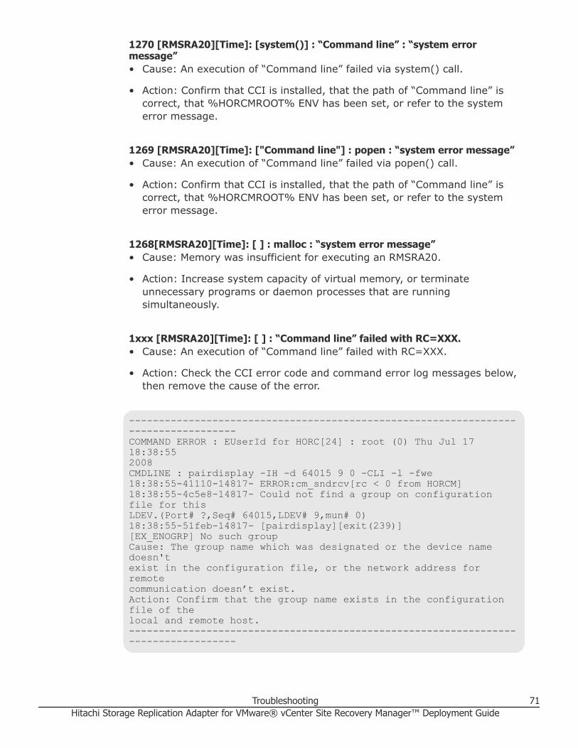
1270 [RMSRA20][Time]: [system()] : “Command line” : “system errormessage”• Cause: An execution of “Command line” failed via system() call.
• Action: Confirm that CCI is installed, that the path of “Command line” iscorrect, that %HORCMROOT% ENV has been set, or refer to the systemerror message.
1269 [RMSRA20][Time]: ["Command line"] : popen : “system error message”• Cause: An execution of “Command line” failed via popen() call.
• Action: Confirm that CCI is installed, that the path of “Command line” iscorrect, that %HORCMROOT% ENV has been set, or refer to the systemerror message.
1268[RMSRA20][Time]: [ ] : malloc : “system error message”• Cause: Memory was insufficient for executing an RMSRA20.
• Action: Increase system capacity of virtual memory, or terminateunnecessary programs or daemon processes that are runningsimultaneously.
1xxx [RMSRA20][Time]: [ ] : “Command line” failed with RC=XXX.• Cause: An execution of “Command line” failed with RC=XXX.
• Action: Check the CCI error code and command error log messages below,then remove the cause of the error.
-----------------------------------------------------------------------------------COMMAND ERROR : EUserId for HORC[24] : root (0) Thu Jul 17 18:38:552008CMDLINE : pairdisplay -IH -d 64015 9 0 -CLI -l -fwe18:38:55-41110-14817- ERROR:cm_sndrcv[rc < 0 from HORCM]18:38:55-4c5e8-14817- Could not find a group on configuration file for thisLDEV.(Port# ?,Seq# 64015,LDEV# 9,mun# 0)18:38:55-51feb-14817- [pairdisplay][exit(239)][EX_ENOGRP] No such groupCause: The group name which was designated or the device name doesn'texist in the configuration file, or the network address for remotecommunication doesn’t exist.Action: Confirm that the group name exists in the configuration file of thelocal and remote host.-----------------------------------------------------------------------------------
Troubleshooting 71Hitachi Storage Replication Adapter for VMware® vCenter Site Recovery Manager™ Deployment Guide

Configuration and status errors
1256 : 1258 : 1260 :[RMSRA20][Time]: [qrysync_chk] : “ Command line” ?GRP = , P/S = , Status = , Fence = , PERCT = .• Cause: The pair status of a source volume specified with syncOnce/
querySyncStatus is incorrect (its pair status is SMPL or PSUS, or thevolume is S-VOL).
• Action: Confirm that the volume status is correct (the volume is P-VOL andits pair status is PAIR or COPY) using the pairdisplay command.
1266 : [RMSRA20][Time]: [qrysync_chk] : The output of “Command line” ismissing.• Cause: The correct format could not be found in the output of the
“Command line” command via syncOnce/querySyncStatus.
• Action: Confirm that the CCI version is correct and supports RMSRA20.
1256 : 1257 : 1260 [RMSRA20][Time]: [failover_chk] : “Command line” ? GRP= , P/S = , Status = , Fence =• Cause: The pair status of a target volume specified with failover is
inappropriate (its pair status is SMPL or COPY, or the volume is P-VOL).
• Action: Confirm that volume status is correct (the volume is S-VOL and itspair status is PAIR) using the pairdisplay command.
1266 : [RMSRA20][Time]: [failover_chk] : The output of “Command line” ismissing.• Cause: The correct format could not be found in the output of the
“Command line” command via failover.
• Action: Confirm that the CCI version is correct and supports RMSRA20.
1256 : 1257 : 1260 [RMSRA20][Time]: [testFailover_chk] : “ Command line” ?GRP = , L/R = , P/S = , Status = , CTG = .• Cause: The pair status of a target volume specified with testFailover is
incorrect (its pair status is SMPL or NOT PAIR, or the volume is P-VOL).
• Action: Confirm that the volume status is correct (the volume is S-VOL ofSI or HTI and its pair status is PAIR) using the pairdisplay command.
1266 : [RMSRA20][Time]: [testfailover_chk] : The output of “Command line”is missing.• Cause: The correct format could not be found in the output of the
“Command line” command via testFailover.
72 TroubleshootingHitachi Storage Replication Adapter for VMware® vCenter Site Recovery Manager™ Deployment Guide
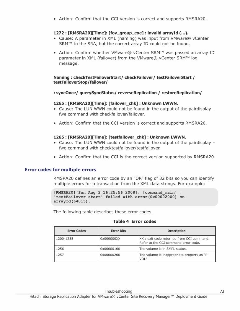
• Action: Confirm that the CCI version is correct and supports RMSRA20.
1272 : [RMSRA20][Time]: [fov_group_exe] : invalid arrayId (…).• Cause: A parameter in XML (naming) was input from VMware® vCenter
SRM™ to the SRA, but the correct array ID could not be found.
• Action: Confirm whether VMware® vCenter SRM™ was passed an array IDparameter in XML (failover) from the VMware® vCenter SRM™ logmessage.
Naming : checkTestFailoverStart/ checkFailover/ testFailoverStart /testFailoverStop/failover/
: syncOnce/ querySyncStatus/ reverseReplication / restoreReplication/
1265 : [RMSRA20][Time]: [failover_chk] : Unknown LWWN.• Cause: The LUN WWN could not be found in the output of the pairdisplay –
fwe command with checkfailover/failover.
• Action: Confirm that the CCI version is correct and supports RMSRA20.
1265 : [RMSRA20][Time]: [testfailover_chk] : Unknown LWWN.• Cause: The LUN WWN could not be found in the output of the pairdisplay –
fwe command with checktestfailover/testfailover.
• Action: Confirm that the CCI is the correct version supported by RMSRA20.
Error codes for multiple errorsRMSRA20 defines an error code by an “OR” flag of 32 bits so you can identifymultiple errors for a transaction from the XML data strings. For example:
[RMSRA20][Sun Aug 3 16:25:56 2008]: [command_main] :'testFailover_start' failed with error(0x00002000) onarrayId(64015).
The following table describes these error codes.
Table 4 Error codes
Error Codes Error Bits Description
1200-1255 0x000000XX XX : exit code returned from CCI command.Refer to the CCI command error code.
1256 0x00000100 The volume is in SMPL status.
1257 0x00000200 The volume is inappropriate property as “P-VOL”
Troubleshooting 73Hitachi Storage Replication Adapter for VMware® vCenter Site Recovery Manager™ Deployment Guide

Error Codes Error Bits Description
1258 0x00000400 The volume is inappropriate property as “S-VOL”
1259 0x00000800 undefined
1260 0x00001000 The volume pair status is not the correctstatus to run the operation.
1261 0x00002000 The volume has no Consistency Group setting.
1262 0x00004000 undefined
1263 0x00008000 undefined
1264 0x00010000 The pairdisplay command has no PWWN in theoutput.
1265 0x00020000 The pairdisplay command has no LUN WWN inthe output.
1266 0x00040000 The pairdisplay command does not supportSRA.
1267 0x00080000 undefined
1268 0x00100000 Memory allocation error
1269 0x00200000 Popen() function of the system was returnedwith ERROR
1270 0x00400000 System() function of the system was returnedwith ERROR
1271 0x00800000 undefined
1272 0x01000000 Error in XML from VMware® vCenter SRM™
1273 0x02000000 undefined
1274 0x04000000 undefined
1275 0x08000000 undefined
1276 0x10000000 undefined
1277 0x20000000 undefined
1278 0x40000000 undefined
1279 0x80000000 undefined
1300 - Memory allocation error for XML input
1301 - Length error in XML parameter strings
1302 - There is no parameter for a command in XML.
1303 - There is no connection parameter for acommand in XML.
1304 - There is no arrayID parameter for a commandin XML.
1305 - There is no arrayID or Device Key parameterfor a command in XML.
1306 - There is not a supported command name inXML.
1307 - Open error for the specified file in XML
1308 - Unexpected CCI command error
74 TroubleshootingHitachi Storage Replication Adapter for VMware® vCenter Site Recovery Manager™ Deployment Guide
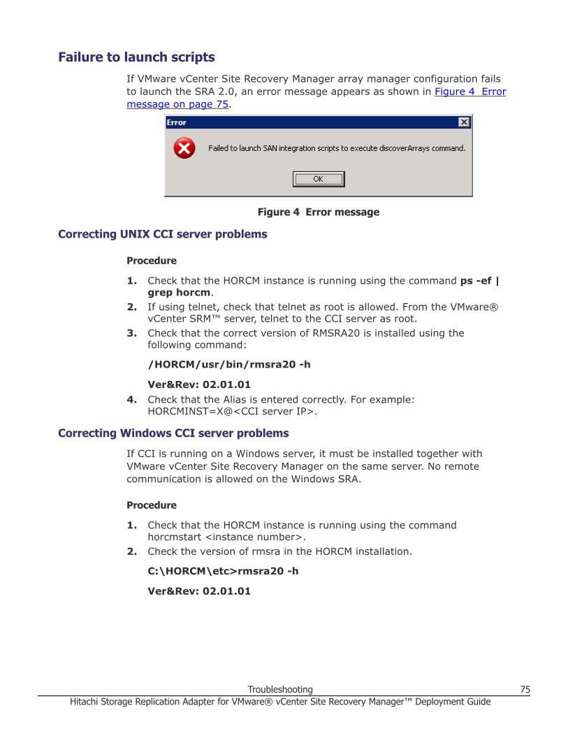
Failure to launch scriptsIf VMware vCenter Site Recovery Manager array manager configuration failsto launch the SRA 2.0, an error message appears as shown in Figure 4 Errormessage on page 75.
Figure 4 Error message
Correcting UNIX CCI server problems
Procedure
1. Check that the HORCM instance is running using the command ps -ef |grep horcm.
2. If using telnet, check that telnet as root is allowed. From the VMware®vCenter SRM™ server, telnet to the CCI server as root.
3. Check that the correct version of RMSRA20 is installed using thefollowing command:
/HORCM/usr/bin/rmsra20 -h
Ver&Rev: 02.01.014. Check that the Alias is entered correctly. For example:
HORCMINST=X@<CCI server IP>.
Correcting Windows CCI server problemsIf CCI is running on a Windows server, it must be installed together withVMware vCenter Site Recovery Manager on the same server. No remotecommunication is allowed on the Windows SRA.
Procedure
1. Check that the HORCM instance is running using the commandhorcmstart <instance number>.
2. Check the version of rmsra in the HORCM installation.
C:\HORCM\etc>rmsra20 -h
Ver&Rev: 02.01.01
Troubleshooting 75Hitachi Storage Replication Adapter for VMware® vCenter Site Recovery Manager™ Deployment Guide

Test failover errorsIf test failover produces errors in Prepare Storage as shown in the historyscreen below, perform the steps in the following procedure.
Figure 5 History screen
Procedure
1. Check the VMware® vCenter SRM™ log on the recovery site (see thefollowing example). Search for the XML code produced by the SRA.Example: VMware® vCenter SRM™ log
------------------------------------>[RMSRA20][Sun Aug 14 02:26:48 2011]: [TF_split] : true -->[RMSRA20][Sun Aug 14 02:26:48 2011]: [RMSRASPLIT] : true -->[RMSRA20][Sun Aug 14 02:26:48 2011]: [RMSRAVER] : 02.01.00 -->[RMSRA20][Sun Aug 14 02:26:48 2011]: [XML_name] : failover -->[RMSRA20][Sun Aug 14 02:26:48 2011]: [XML_con_id] : HORCM_REMOTE_LOCAL-->[RMSRA20][Sun Aug 14 02:26:48 2011]: [XML_con_addr] :[email protected] -->[RMSRA20][Sun Aug 14 02:26:48 2011]: [XML_outfile] :C:\Windows\TEMP\vmware-SYSTEM\sra-output-928-0 -->[RMSRA20][Sun Aug 14 02:26:48 2011]: [XML_statfile] :C:\Windows\TEMP\vmware-SYSTEM\sra-status-929-0 -->[RMSRA20][Sun Aug 14 02:26:48 2011]: [XML_logdir] :C:\ProgramData\VMware\VMware vCenter Site RecoveryManager\Logs\SRAs\RMHTC -->[RMSRA20][Sun Aug 14 02:26:48 2011]: [XML_loglvl] : verbose
76 TroubleshootingHitachi Storage Replication Adapter for VMware® vCenter Site Recovery Manager™ Deployment Guide

-->[RMSRA20][Sun Aug 14 02:26:48 2011]: [XML_arrayId] : 53011 -->[RMSRA20][Sun Aug 14 02:26:48 2011]: [XML_peerId] : -->[RMSRA20][Sun Aug 14 02:26:48 2011]: [RMSRATOV] : 60 sec -->[RMSRA20][Sun Aug 14 02:26:48 2011]: [RMSRATMU] : 0 -->[RMSRA20][Sun Aug 14 02:26:48 2011]: [TF_split] : -->[RMSRA20][Sun Aug 14 02:26:48 2011]: [XML_Con_ID] : HORCM_REMOTE_LOCAL-->[RMSRA20][Sun Aug 14 02:26:48 2011]: [XML_Con_ADR] :[email protected] -->[RMSRA20][Sun Aug 14 02:26:48 2011]: [XML_DeviceKey] : 238 -->[RMSRA20][Sun Aug 14 02:26:48 2011]: [XML_RecvPID] : -->[RMSRA20][Sun Aug 14 02:26:48 2011]: [XML_DeviceKey] : 242 -->[RMSRA20][Sun Aug 14 02:26:48 2011]: [XML_RecvPID] : -->[RMSRA20][Sun Aug 14 02:26:48 2011]: [XML_DeviceKey] : 243 -->[RMSRA20][Sun Aug 14 02:26:48 2011]: [XML_RecvPID] : -->[RMSRA20][Sun Aug 14 02:26:48 2011]: [XML_DeviceKey] : 246 -->[RMSRA20][Sun Aug 14 02:26:48 2011]: [XML_RecvPID] : -->[RMSRA20][Sun Aug 14 02:26:48 2011]: [horcmconn_exe] : '/usr/bin/raidqry-IH -l 2>/dev/null 1>/dev/null' returned with RC=0 on HORCMINST=0.-----------------------------------
Note: In this case there is no ShadowImage or Copy-on-WriteSnapshot for test failover, therefore the SplitReplication parametermust be set to true. [RMSRASPLIT]:true is logged on both theVMware® vCenter SRM™ and UNIX servers (if UNIX is used forCCI in the UNIX server root profile, see Correcting UNIX CCIserver problems on page 75 for more information).
2. [RMSRASPLIT] : false must be set. However, this must be changed totrue both on the VMware® vCenter SRM™ server and the UNIX servers(if UNIX is used for CCI in the UNIX servers root profile, see CorrectingUNIX CCI server problems on page 75 for more information).After corrections are made, the test is complete. XML should be similar tothe following example.Example: VMware® vCenter SRM™ log after corrections
------------------------------------>[RMSRA20][Sun Aug 14 02:26:48 2011]: [RMSRAVER] : 02.01.00 -->[RMSRA20][Sun Aug 14 02:26:48 2011]: [XML_name] : failover -->[RMSRA20][Sun Aug 14 02:26:48 2011]: [XML_con_id] : HORCM_REMOTE_LOCAL-->[RMSRA20][Sun Aug 14 02:26:48 2011]: [XML_con_addr] :
Troubleshooting 77Hitachi Storage Replication Adapter for VMware® vCenter Site Recovery Manager™ Deployment Guide

[email protected] -->[RMSRA20][Sun Aug 14 02:26:48 2011]: [XML_outfile] :C:\Windows\TEMP\vmware-SYSTEM\sra-output-928-0 -->[RMSRA20][Sun Aug 14 02:26:48 2011]: [XML_statfile] :C:\Windows\TEMP\vmware-SYSTEM\sra-status-929-0 -->[RMSRA20][Sun Aug 14 02:26:48 2011]: [XML_logdir] :C:\ProgramData\VMware\VMware vCenter Site RecoveryManager\Logs\SRAs\RMHTC -->[RMSRA20][Sun Aug 14 02:26:48 2011]: [XML_loglvl] : verbose -->[RMSRA20][Sun Aug 14 02:26:48 2011]: [XML_arrayId] : 53011 -->[RMSRA20][Sun Aug 14 02:26:48 2011]: [XML_peerId] : -->[RMSRA20][Sun Aug 14 02:26:48 2011]: [RMSRATOV] : 60 sec -->[RMSRA20][Sun Aug 14 02:26:48 2011]: [RMSRATMU] : 0 -->[RMSRA20][Sun Aug 14 02:26:48 2011]: [TF_split] : -->[RMSRA20][Sun Aug 14 02:26:48 2011]: [XML_Con_ID] : HORCM_REMOTE_LOCAL-->[RMSRA20][Sun Aug 14 02:26:48 2011]: [XML_Con_ADR] :[email protected] -->[RMSRA20][Sun Aug 14 02:26:48 2011]: [XML_DeviceKey] : 238 -->[RMSRA20][Sun Aug 14 02:26:48 2011]: [XML_RecvPID] : -->[RMSRA20][Sun Aug 14 02:26:48 2011]: [XML_DeviceKey] : 242 -->[RMSRA20][Sun Aug 14 02:26:48 2011]: [XML_RecvPID] : -->[RMSRA20][Sun Aug 14 02:26:48 2011]: [XML_DeviceKey] : 243 -->[RMSRA20][Sun Aug 14 02:26:48 2011]: [XML_RecvPID] : -->[RMSRA20][Sun Aug 14 02:26:48 2011]: [XML_DeviceKey] : 246 -->[RMSRA20][Sun Aug 14 02:26:48 2011]: [XML_RecvPID] : -->[RMSRA20][Sun Aug 14 02:26:48 2011]: [horcmconn_exe] : '/usr/bin/raidqry-IH -l 2>/dev/null 1>/dev/null' returned with RC=0 on HORCMINST=0.-----------------------------------
Collecting information before contacting customer supportPlease collect the following information before contacting customer support.
VMware® vCenter SRM™/SRA local configurationOn Windows where VMware® vCenter SRM™ is running, perform thefollowing procedures.
Procedure
1. Collect the VMware® vCenter SRM™ log file on Windows on bothprotected and recovery sites. Collect the following VMware® vCenter
78 TroubleshootingHitachi Storage Replication Adapter for VMware® vCenter Site Recovery Manager™ Deployment Guide

SRM™ log file including the error messages of “[RMSRA]” and “VMware®vCenter SRM™ ERROR messages” and the CCI command error log.
%ALLUSERSPROFILE%\ Application Data\VMware\VMware SiteRecovery Manager\Logs\vmware*.log
2. Collect the outputs of the following command on HORCMINST=XX(instance# for SRA):• set• %HORCMROOT%\HORCM\etc\raidqry -l• %HORCMROOT%\HORCM\etc\raidqry -g• %HORCMROOT%\HORCM\etc\pairdisplay -IH -g ??? -CLI -l -fwe
(where ??? is a group name shown by raidqry -g)• %HORCMROOT%\HORCM\etc\raidscan -IH -p port(i.e. cl1-a-0) - CLI
(port where connecting to ESX/ESXi server)
If ShadowImage is installed:• %HORCMROOT%\HORCM\etc\pairdisplay -g ??? -CLI -l -few -m cas
(where ??? is a group name shown by raidqry -g)
VMware® vCenter SRM™/SRA remote configurationOn Windows where VMware® vCenter SRM™ is running, and on UNIX whereCCI is running, perform the following procedures.
Procedure
1. Collect the VMware® vCenter SRM™ log file on Windows on bothprotected and recovery site.
2. Collect the following VMware® vCenter SRM™ log file including the errormessages of “[RMSRA]” and “SRM ERROR messages” and the CCIcommand error log.
%ALLUSERSPROFILE%\ Application Data\VMware\VMware Site Recovery Manager\Logs\vmware*.log
3. Collect the outputs of the following command onHORCMINST=XX(instance# for SRA) on remote UNIX.• env
• raidqry -l
• raidqry -g
• pairdisplay -IH -g ??? -CLI -l -fwe (where ??? is a group name shownby raidqry -g)
• raidscan -IH -p port(i.e. cl1-a-0) -CLI (port where connecting to ESX/ESXi sever)
If ShadowImage is installed, collect the following:
Troubleshooting 79Hitachi Storage Replication Adapter for VMware® vCenter Site Recovery Manager™ Deployment Guide

• pairdisplay -g ??? -CLI -l -few -m cas (where ??? is a group nameshown by raidqry -g)
Calling Hitachi Vantara customer supportIf you need to call Hitachi Vantara customer support, make sure to provide asmuch information about the problem as possible, including:• The circumstances surrounding the error or failure.
• The exact content of any messages displayed on the host or StorageNavigator.
• Service information messages (SIMs), including reference codes andseverity levels, displayed by Storage Navigator.
• The information collected in Collecting information before contactingcustomer support on page 78.
The Hitachi Vantara customer support staff is available 24 hours a day, sevendays a week. If you need technical support, log on to Hitachi Vantara SupportConnect for contact information: https://support.hds.com/en_us/contact-us.html.
80 TroubleshootingHitachi Storage Replication Adapter for VMware® vCenter Site Recovery Manager™ Deployment Guide

5SRA Change Log
This chapter provides the change log for Hitachi Storage Replication Adapter(SRA).
□ Change log for SRA
SRA Change Log 81Hitachi Storage Replication Adapter for VMware® vCenter Site Recovery Manager™ Deployment Guide

Change log for SRAThe following table provides the change log for SRA.
SRA version command.pl revision* Description of change
2.1.4 2.7 Initial release of SRA 2.1.4
2.1.4 2.8 Fixed the following problem: [Problem] Testfailover with local replication pairs fails, if the localreplication pairs use MU# other than 0 and SSHremote connection is used between SRA and CCI.
2.2 2.9 • Added support for global-active device (GAD)and VSP Fx00 models.
• Discontinued support for TagmaStore USP,TagmaStore NSC, and Adaptable ModularStorage.
• Deprecated the iSCSI protocol supportingHUS.
2.3 2.9 • Added iSCSI support as the protocol for theconnection between the storage system (VSPG1000, VSP G1500, VSP F1500, VSP Gx00models, VSP Fx00 models, and HUS) andVMware ESXi.
• Discontinued support for the telnet protocol forUNIX version of CCI.
2.3.1 2.9 • Added support for the GAD configuration inVMware Site Recovery Manager 6.5environment.
• Fixed the following problem:○ [Problem] When "Planned Migration" is
performed in the GAD configuration, theerror message of "Unexpected element'Identity' found" appears, and "Preparestorage for migration at protected site"process ends abnormally.
○ This problem might occur when all thefollowing conditions 1) and 2) are met, and"Planned Migration" is performed.1. ”Disaster Recovery” was performed
after a failure had occurred on theprotected site.
2. The protected site recovered from thefailure after condition 1.
*Note: The revision is described in the header of the command.pl file. The command.pl file islocated in <SRM install directory>\storage\sra\RMHTC.
82 SRA Change LogHitachi Storage Replication Adapter for VMware® vCenter Site Recovery Manager™ Deployment Guide

AConfigurations with both sites active
This chapter describes configurations in which both protected and recoveryVMs are present on the local and remote sites. The following topics arediscussed:
□ Protecting both sites
□ HORCM definition file setup
Configurations with both sites active 83Hitachi Storage Replication Adapter for VMware® vCenter Site Recovery Manager™ Deployment Guide

Protecting both sitesThis section describes the typical SRM configuration with one protected site(A) and one recovery site (B). You create HORCM definition files explicitlydefining protected and recovery volumes.
You can also set up a configuration in which both sites are active, thusproviding protection for each site. In this scenario, some VMs on site A areprotected with recovery on site B; and some VMs on site B are protected,with recovery on site A.
The following illustration shows a configuration with the protected andrecovery sites active.
84 Configurations with both sites activeHitachi Storage Replication Adapter for VMware® vCenter Site Recovery Manager™ Deployment Guide

HORCM definition file setupHORCM files must reflect your configuration. The following four figures showexamples of the local and remote site HORCM configuration files(HORCM.conf) for the configuration shown in the preceding figure.
Site A horcm0
HORCM_MON#ip_address service poll(10ms) timeout(10ms)172.17.46.38 horcm0 1000 3000
HORCM_CMD#dev_name\\.\CMD-64015
HORCM_LDEV#dev_group dev_name Serial# CU:LDEV(LDEV#) MU##Replication Site A to Site BTC_UR_SRM1 01A_01B 64015 00:0A#Replication Site B to Site BTC_UR_SRM2 01B_01A 64015 00:1B#CoW or SI copy for testfailoverSI_SRM2 SI_01B_01C 64015 00:1B 0
HORCM_INST#dev_group ip_address serviceTC_UR_SRM1 172.17.46.39 horcm1TC_UR_SRM2 172.17.46.39 horcm1SI_SRM2 172.17.46.38 horcm3
Site A SI/COW horcm3
HORCM_MON#ip_address service poll(10ms) timeout(10ms)172.17.46.38 horcm3 1000 3000
HORCM_CMD#dev_name\\.\CMD-64015
HORCM_LDEV#dev_group dev_name Serial# CU:LDEV(LDEV#) MU#SI_SRM2 SI_01B_01C 64015 00:1C
HORCM_INST#dev_group ip_address serviceSI_SRM2 172.17.46.38 horcm0
Site B horcm1
HORCM_MON#ip_address service poll(10ms) timeout(10ms)
Configurations with both sites active 85Hitachi Storage Replication Adapter for VMware® vCenter Site Recovery Manager™ Deployment Guide

172.17.46.39 horcm1 1000 3000
HORCM_CMD#dev_name\\.\CMD-64016
HORCM_LDEV#dev_group dev_name Serial# CU:LDEV(LDEV#) MU##Replication Site A to Site BTC_UR_SRM1 01A_01B 64016 00:0B#Replication Site B to Site ATC_UR_SRM2 01B_01A 64016 00:1A#CoW or SI copy for testfailoverSI_SRM1 SI_01B_01C 64016 00:0B 0
HORCM_INST#dev_group ip_address serviceTC_UR_SRM1 172.17.46.38 horcm0TC_UR_SRM2 172.17.46.38 horcm0SI_SRM1 172.17.46.39 horcm2
Site B SI/COW horcm2
HORCM_MON#ip_address service poll(10ms) timeout(10ms)172.17.46.39 horcm2 1000 3000
HORCM_CMD#dev_name\\.\CMD-64016
HORCM_LDEV#dev_group dev_name Serial# CU:LDEV(LDEV#) MU#SI_SRM1 SI_01B_01C 64016 00:0C
HORCM_INST#dev_group ip_address serviceSI_SRM1 172.17.46.39 horcm1
86 Configurations with both sites activeHitachi Storage Replication Adapter for VMware® vCenter Site Recovery Manager™ Deployment Guide

IndexA
AMShost group requirement 28
array managersconfiguring 50enabling 54
At-Time Split operationplanning 23
CCommand Control Interface (CCI) 16
consistency groups 25installing 33location options 22overview 13splitting pairs 25
command deviceconfiguring 33creating 33
command device authentication 62
Ddeployment workflow 32
Eenvironment variables settings 43
Gglobal-active device
configuration prerequisites 26
HHORCM
creating pairs 41creating test copy 42editing HORCM.conf files 36setting up HORCM configuration definition files36
starting an instance 41
Iin-system replication 23
RRecovery
failback 64failover operation 64reprotect 64
Requirementsoperating systems 20server locations for SRA/SRM/CCI 20supported micro code levels 20supported replication software 20Unix host 20
SShadowImage
port requirement 24splitting pairs 25SRA
checking version 49configuring 46installing 47overview 14removing SRA version 48replication support 14storage support 14storage, replication software products 14version 20
SRA/SRMlocation options 22setup workflow 32
SRMXML errors 68
SRM hostsetting variables 46
SRM/SRAhow it works 17
Index 87Hitachi Storage Replication Adapter for VMware® vCenter Site Recovery Manager™ Deployment Guide

Ttesting
creating copy 42setting environment variables 43
troubleshooting 67TrueCopy
fence level 26
UUnix host
setting variables 47upgrading CCI 33
UNIX systems 62
Vverifying devices 54VMware environment 20
XXML errors 68
88 IndexHitachi Storage Replication Adapter for VMware® vCenter Site Recovery Manager™ Deployment Guide

Hitachi Storage Replication Adapter for VMware® vCenter Site Recovery Manager™ Deployment Guide

Corporate Headquarters2845 Lafayette StreetSanta Clara, CA 95050-2639 USAwww.HitachiVantara.comcommunity.HitachiVantara.com
Regional Contact InformationAmericas: +1 866 374 5822 or [email protected], Middle East and Africa: +44 (0) 1753 618000 or [email protected] Asia Pacific: +852 3189 7900 or [email protected]
Hitachi Vantara