hit-re 500 v3 injection mortar...3 updated: may-19 design resistance anchor size eta-16/0143, issue...
TRANSCRIPT

HIT-RE 500 V3 INJECTION MORTAR
Technical DatasheetUpdate: May-19

1 Updated: May-19
HIT-RE 500 V3 injection mortar Anchor design (ETAG 001) / Rods&Sleeves / Concrete
Injection mortar system Benefits
Foil pack: HIT-RE 500 V3
(available in 330, 500 and 1400 ml cartridges)
- SafeSet technology: Simplified
method of borehole preparation
using either Hilti hollow drill bit for
hammer drilling or Roughening
tool for diamond cored
applications
- Suitable for cracked/non-cracked
concrete C 20/25 to C 50/60
- High loading capacity
- Suitable for dry and water
saturated concrete
- Hilti Technical Data for under
water application
- High corrosion resistance
- Long working time at elevated
temperatures
- Cures down to -5°C
- Odourless epoxy
Anchor rod:
HIT-V
HIT-V-F
HIT-V-R
HIT-V-HCR
AM 8.8 (HDG)
(M8-M39)
Internally threaded
sleeve:
HIS-N,
HIS-RN
(M8-M20)
Base material Installation conditions
Concrete (non-cracked)
Concrete (cracked)
Hammer drilled holes
Diamond drilled holes
Hilti SafeSet technology
Small edge distance and
spacing
Variable embedment
depth
Load conditions Other information
Static/ quasi-static
Seismic, ETA-C1, C2
Fire resistance
European Technical
Assessment
CE conformity PROFIS design
Software
Corrosion resistance
High corrosion
resistance a)
a) Applications only with HIT-V anchor rods
a) All data given in this section according to ETA-16/0143, issue 2017-07-12.
b) Fire test report only available for HIT-V rods.
Approvals / certificates
Description Authority / Laboratory No. / date of issue
European Technical Assessment a) CSTB ETA-16/0143 / 2017-07-12
Shockproof fastenings in civil
defence installations
Federal Office for Civil Protection,
Bern BZS D 16-601/ 2016-08-31
Fire test report b) MFPA Leipzig GS 3.2/15-361-4 / 2016-08-04
Updated: May-19 2
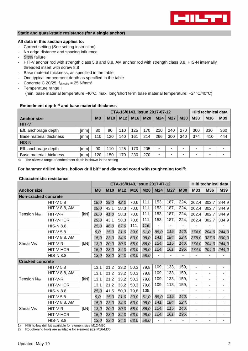
Static and quasi-static resistance (for a single anchor)
All data in this section applies to:
- Correct setting (See setting instruction)
- No edge distance and spacing influence
- Steel failure
- HIT-V anchor rod with strength class 5.8 and 8.8, AM anchor rod with strength class 8.8, HIS-N internally
threaded insert with screw 8.8
- Base material thickness, as specified in the table
- One typical embedment depth as specified in the table
- Concrete C 20/25, fck,cube = 25 N/mm²
- Temperature range I
(min. base material temperature -40°C, max. long/short term base material temperature: +24°C/40°C)
a) The allowed range of embedment depth is shown in the setting
For hammer drilled holes, hollow drill bit1) and diamond cored with roughening tool2): Characteristic resistance
Anchor size
ETA-16/0143, issue 2017-07-12 Hilti technical data
M8 M10 M12 M16 M20 M24 M27 M30 M33 M36 M39
Non-cracked concrete
Tension NRk
HIT-V 5.8
[kN]
18,0 29,0 42,0 70,6 111,9
153,7
187,8
224,0
262,4 302,7 344,9
HIT-V 8.8, AM 8.8
29,0 43,1 58,3 70,6 111,9
153,7
187,8
224,0
262,4 302,7 344,9
HIT-V-R 26,0 41,0 58,3 70,6 111,9
153,7
187,8
224,0
262,4 302,7 344,9
HIT-V-HCR 29,0 43,1 58,3 70,6 111,9
153,7
187,8
224,0
262,4 302,7 334,9
HIS-N 8.8 25,0 46,0 67,0 111,9
116,0
- - - - - -
Shear VRk
HIT-V 5.8
[kN]
9,0 15,0 21,0 39,0 61,0 88,0 115,0
140,0
174,0 204,0 244,0
HIT-V 8.8, AM 8.8
15,0 23,0 34,0 63,0 98,0 141,0
184,0
224,0
278,0 327,0 390,0
HIT-V-R 13,0 20,0 30,0 55,0 86,0 124,0
115,0
140,0
174,0 204,0 244,0
HIT-V-HCR 15,0 23,0 34,0 63,0 98,0 124,0
161,0
196,0
174,0 204,0 244,0
HIS-N 8.8 13,0 23,0 34,0 63,0 58,0 - - - - - -
Cracked concrete
Tension NRk
HIT-V 5.8
[kN]
13,1 21,2 33,2 50,3 79,8 109,6
133,9
159,7
- - -
HIT-V 8.8, AM 8.8
13,1 21,2 33,2 50,3 79,8 109,6
133,9
159,7
- - -
HIT-V-R 13,1 21,2 33,2 50,3 79,8 109,6
133,9
159,7
- - -
HIT-V-HCR 13,1 21,2 33,2 50,3 79,8 109,6
113,9
159,7
- - -
HIS-N 8.8 25,0 41,5 50,3 79,8 105,7
- - - - - -
Shear VRk
HIT-V 5.8
[kN]
9,0 15,0 21,0 39,0 61,0 88,0 115,0
140,0
- - -
HIT-V 8.8, AM 8.8
15,0 23,0 34,0 63,0 98,0 141,0
184,0
224,0
- - -
HIT-V-R 13,0 20,0 30,0 55,0 86,0 124,0
115,0
140,0
- - -
HIT-V-HCR 15,0 23,0 34,0 63,0 98,0 124,0
161,0
196,0
- - -
HIS-N 8.8 13,0 23,0 34,0 63,0 58,0 - - - - - -
1) Hilti hollow drill bit available for element size M12-M30. 2) Roughening tools are available for element size M16-M30.
Embedment depth a) and base material thickness
Anchor size
ETA-16/0143, issue 2017-07-12 Hilti technical data
M8 M10 M12 M16 M20 M24 M27 M30 M33 M36 M39
HIT-V
Eff. anchorage depth [mm] 80 90 110 125 170 210 240 270 300 330 360
Base material thickness [mm] 110 120 140 161 214 266 300 340 374 410 444
HIS-N
Eff. anchorage depth [mm] 90 110 125 170 205 - - - - - -
Base material thickness [mm] 120 150 170 230 270 - - - - - -
3 Updated: May-19
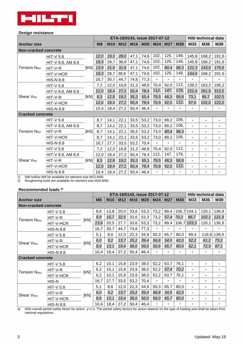
Design resistance
Anchor size
ETA-16/0143, issue 2017-07-12 Hilti technical data
M8 M10 M12 M16 M20 M24 M27 M30 M33 M36 M39
Non-cracked concrete
Tension NRd
HIT-V 5.8
[kN]
12,0 19,3 28,0 47,1 74,6 102,5
125,2
149,4
145,8 168,2 191,6
HIT-V 8.8, AM 8.8 19,3 28,7 38,8 47,1 74,6 102,5
125,2
149,4
145,8 168,2 191,6
HIT-V-R 13,9 21,9 31,6 47,1 74,6 102,5
80,4 98,3 121,3 143,0 170,6
HIT-V-HCR 19,3 28,7 38,8 47,1 74,6 102,5
125,2
149,4
144,6 168,2 191,6
HIS-N 8.8 16,7 30,7 44,7 74,6 77,3 - - - - - -
Shear VRd
HIT-V 5.8
[kN]
7,2 12,0 16,8 31,2 48,8 70,4 92,0 112,0
139,2 163,2 195,2
HIT-V 8.8, AM 8.8 12,0 18,4 27,2 50,4 78,4 112,8
147,2
179,2
222,4 261,6 312,0
HIT-V-R 8,3 12,8 19,2 35,3 55,4 79,5 48,3 58,8 73,1 85,7 102,5
HIT-V-HCR 12,0 18,4 27,2 50,4 78,4 70,9 92,0 112,0
87,0 102,0 122,0
HIS-N 8.8 10,4 18,4 27,2 50,4 46,4 - - - - - -
Cracked concrete
Tension NRd
HIT-V 5.8
[kN]
8,7 14,1 22,1 33,5 53,2 73,0 89,2 106,5
- - -
HIT-V 8.8, AM 8.8 8,7 14,1 22,1 33,5 53,2 73,0 89,2 106,5
- - -
HIT-V-R 8,7 14,1 22,1 35,5 53,2 73,0 80,4 98,3 - - -
HIT-V-HCR 8,7 14,1 22,1 33,5 53,2 73,0 89,2 106,5
- - -
HIS-N 8.8 16,7 27,7 33,5 53,2 70,4 - - - - - -
Shear VRd
HIT-V 5.8
[kN]
7,2 12,0 16,8 31,2 48,8 70,4 92,0 112,0
- - -
HIT-V 8.8, AM 8.8 12,0 18,4 27,2 50,4 78,4 112,8
147,2
179,2
- - -
HIT-V-R 8,3 12,8 19,2 35,3 55,1 79,5 48,3 58,8 - - -
HIT-V-HCR 12,0 18,4 27,2 50,4 78,4 70,9 92,0 112,0
- - -
HIS-N 8.8 10,4 18,4 27,2 50,4 46,4 - - - - - -
1) Hilti hollow drill bit available for element size M12-M30. 2) Roughening tools are available for element size M16-M30.
Recommended loads a)
Anchor size
ETA-16/0143, issue 2017-07-12 Hilti technical data
M8 M10 M12 M16 M20 M24 M27 M30 M33 M36 M39
Non-cracked concrete
Tension NRec
HIT-V 5.8
[kN]
8,6 13,8 20,0 33,6 53,3 73,2 89,4 106,7 104,1 120,1 136,9
HIT-V-R 9,9 15,7 22,5 33,6 53,3 73,2 57,4 70,2 86,7 102,1 121,9
HIT-V-HCR 13,8 20,5 27,7 33,6 53,3 73,2 89,4 106,7 103,3 120,1 136,9
HIS-N 8.8 16,7 30,7 44,7 74,6 77,3 - - - - - -
Shear VRec
HIT-V 5.8
[kN]
5,1 8,6 12,0 22,3 34,9 50,3 65,7 80,0 99,4 116,6 139,4
HIT-V-R 6,0 9,2 13,7 25,2 39,4 56,8 34,5 42,0 52,2 61,2 73,2
HIT-V-HCR 8,6 13,1 19,4 36,0 56,0 50,6 65,7 80,0 62,1 72,9 87,1
HIS-N 8.8 10,4 18,4 27,2 50,4 46,4 - - - - - -
Cracked concrete
Tension NRec
HIT-V 5.8
[kN]
6,2 10,1 15,8 23,9 38,0 52,2 63,7 76,1 - - -
HIT-V-R 6,2 10,1 15,8 23,9 38,0 52,2 57,4 70,2 - - -
HIT-V-HCR 6,2 10,1 15,8 23,9 38,0 52,2 63,7 76,1 - - -
HIS-N 16,7 27,7 33,5 53,2 70,4 - - - - - -
Shear VRec
HIT-V 5.8
[kN]
5,1 8,6 12,0 22,3 34,9 50,3 65,7 80,0 - - -
HIT-V-R 6,0 9,2 13,7 25,2 39,4 56,8 34,5 42,0 - - -
HIT-V-HCR 8,6 13,1 19,4 36,0 56,0 56,0 65,7 80,0 - - -
HIS-N 8.8 10,4 18,4 27,2 50,4 46,4 - - - - - -
a) With overall partial safety factor for action γ=1,4. The partial safety factors for action depend on the type of loading and shall be taken from national regulations.

Updated: May-19 4
For diamond drilling a):
Characteristic resistance Anchor size M8 M10 M12 M16 M20 M24 M27 M30
Non-cracked concrete
Tension NRk HIT-V 5.8
[kN] 18,0 29,0 42,0 70,6 111,9 153,7 187,8 224,0
HIT-V 8.8, AM 8.8 24,1 33,9 49,8 70,6 111,9 153,7 187,8 224,0
Shear VRk HIT-V 5.8
[kN] 9,0 15,0 21,0 39,0 61,0 88,0 115,0 140,0
HIT-V 8.8, AM 8.8 15,0 23,0 34,0 63,0 98,0 141,0 184,0 224,0 a) No data for HIS-N when diamond coring without roughening tools.
Design resistance Anchor size M8 M10 M12 M16 M20 M24 M27 M30
Non-cracked concrete
Tension NRd HIT-V 5.8
[kN] 12,0 18,8 27,6 33,6 53,3 73,2 89,4 106,7
HIT-V 8.8, AM 8.8 13,4 18,8 27,6 33,6 53,3 73,2 89,4 106,7
Shear VRd HIT-V 5.8
[kN] 7,2 12,0 16,8 31,2 48,8 70,4 92,0 112,0
HIT-V 8.8, AM 8.8 12,0 18,4 27,2 50,4 78,4 112,8 147,2 179,2 a) No data for HIS-N when diamond coring without roughening tools.
Recommended loads b)
Anchor size M8 M10 M12 M16 M20 M24 M27 M30
Non-cracked concrete
Tensile NRec HIT-V 5.8 [kN] 8,6 13,5 19,7 24,0 38,1 52,3 63,9 76,2
Shear VRec HIT-V 5.8 [kN] 5,1 8,6 12,0 22,3 34,9 50,3 65,7 80,0 a) No data for HIS-N when diamond coring without roughening tools. b) With overall partial safety factor for action γ=1,4. The partial safety factors for action depend on the type of loading and shall be taken from
national regulations.
5 Updated: May-19
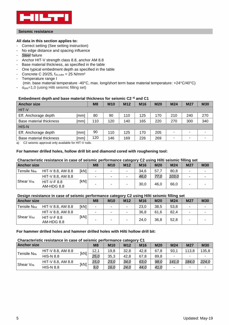
Seismic resistance
All data in this section applies to:
- Correct setting (See setting instruction)
- No edge distance and spacing influence
- Steel failure
- Anchor HIT-V strength class 8.8, anchor AM 8.8 - Base material thickness, as specified in the table
- One typical embedment depth as specified in the table
- Concrete C 20/25, fck,cube = 25 N/mm² - Temperature range I (min. base material temperature -40°C, max. long/short term base material temperature: +24°C/40°C) - αgap=1,0 (using Hilti seismic filling set)
a) C2 seismic approval only available for HIT-V rods.
For hammer drilled holes, hollow drill bit and diamond cored with roughening tool: Characteristic resistance in case of seismic performance category C2 using Hilti seismic filling set Anchor size M8 M10 M12 M16 M20 M24 M27 M30
Tensile NRk HIT-V 8.8, AM 8.8 [kN] - - - 34,6 57,7 80,8 - -
Shear VRk
HIT-V 8.8, AM 8.8
[kN]
- - - 46,0 77,0 103,0 - -
HIT-V-F 8.8 AM-HDG 8.8
- - - 30,0 46,0 66,0 - -
Design resistance in case of seismic performance category C2 using Hilti seismic filling set Anchor size M8 M10 M12 M16 M20 M24 M27 M30
Tensile NRd HIT-V 8.8, AM 8.8 [kN] - - - 23,0 38,5 53,8 - -
Shear VRd
HIT-V 8.8, AM 8.8
[kN]
- - - 36,8 61,6 82,4 - -
HIT-V-F 8.8 AM-HDG 8.8
- - - 24,0 36,8 52,8 - -
For hammer drilled holes and hammer drilled holes with Hilti hollow drill bit: Characteristic resistance in case of seismic performance category C1 Anchor size M8 M10 M12 M16 M20 M24 M27 M30
Tensile NRk HIT-V 8.8, AM 8.8
[kN] 12,1 19,8 32,8 42,8 67,8 93,1 113,8 135,8
HIS-N 8.8 25,0 35,3 42,8 67,8 89,8 - - -
Shear VRk HIT-V 8.8, AM 8.8
[kN] 15,0 23,0 34,0 63,0 98,0 141,0 184,0 224,0
HIS-N 8.8 9,0 16,0 24,0 44,0 41,0 - - -
Embedment depth and base material thickness for seismic C2 a) and C1
Anchor size M8 M10 M12 M16 M20 M24 M27 M30
HIT-V
Eff. Anchorage depth [mm] 80 90 110 125 170 210 240 270
Base material thickness [mm] 110 120 140 165 220 270 300 340
HIS-N
Eff. Anchorage depth [mm] 90 110 125 170 205 - - -
Base material thickness [mm] 120 146 169 226 269 - - -

Updated: May-19 6
Design resistance in case of seismic performance category C1 Anchor size M8 M10 M12 M16 M20 M24 M27 M30
Tensile NRd HIT-V 8.8, AM 8.8
[kN] 8,0 13,2 21,8 28,5 45,2 62,1 75,9 90,5
HIS-N 8.8 16,7 23,5 28,5 45,2 59,9 - - -
Shear VRd HIT-V 8.8, AM 8.8
[kN] 12,0 18,4 27,2 50,4 78,4 112,8 147,2 179,2
HIS-N 8.8 7,2 12,8 19,2 35,2 32,8 - - -
Materials
Mechanical properties for HIT-V
Anchor size ETA-16/0143, issue 2017-07-12
Hilti Technical
data
M8 M10 M12 M16 M20 M24 M27 M30 M33 M36 M39
Nominal
tensile
strength fuk
HIT-V 5.8(F)
[N/mm²]
500 500 500 500 500 500 500 500 500 500 500
HIT-V 8.8(F) 800 800 800 800 800 800 800 800 800 800 800
AM 8.8(HDG) 800 800 800 800 800 800 800 800 800 800 800
HIT-V-R 700 700 700 700 700 700 500 500 500 500 500
HIT-V-HCR 800 800 800 800 800 700 700 700 500 500 500
Yield strength
fyk
HIT-V 5.8(F)
[N/mm²]
400 400 400 400 400 400 400 400 400 400 400
HIT-V 8.8(F) 640 640 640 640 640 640 640 640 640 640 640
AM 8.8(HDG) 640 640 640 640 640 640 640 640 640 640 640
HIT-V-R 450 450 450 450 450 450 210 210 210 210 210
HIT-V-HCR 640 640 640 640 640 400 400 400 250 250 250
Stressed cross-
section As HIT-V AM 8.8 [mm²] 36,6 58,0 84,3 157 245 353 459 561 694 817 976
Moment of
resistance W HIT-V AM 8.8 [mm³] 31,2 62,3 109 277 541 935 1387 1874 2579 3294 4301
Mechanical properties for HIS-N
Anchor size ETA-16/0143, issue 2017-07-12
M8 M10 M12 M16 M20
Nominal
tensile
strength fuk
HIS-N
[N/mm²]
490 490 460 460 460
Screw 8.8 800 800 800 800 800
HIS-RN 700 700 700 700 700
Screw A4-70 700 700 700 700 700
Yield strength
fyk
HIS-N
[N/mm²]
410 410 375 375 375
Screw 8.8 640 640 640 640 640
HIS-RN 350 350 350 350 350
Screw A4-70 450 450 450 450 450
Stressed cross-
section As
HIS-(R)N [mm²]
51,5 108,0 169,1 256,1 237,6
Screw 36,6 58 84,3 157 245
Moment of
resistance W
HIS-(R)N [mm³]
145 430 840 1595 1543
Screw 31,2 62,3 109 277 541
7 Updated: May-19
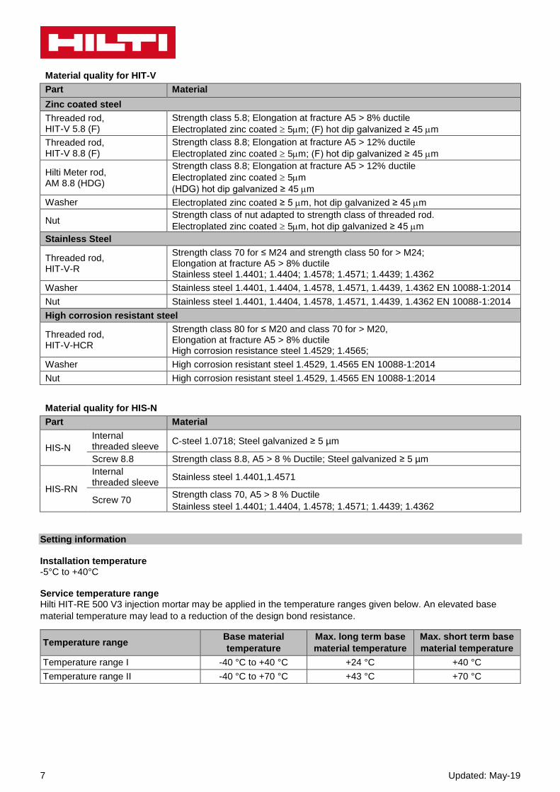
Material quality for HIT-V
Part Material
Zinc coated steel
Threaded rod, HIT-V 5.8 (F)
Strength class 5.8; Elongation at fracture A5 > 8% ductile
Electroplated zinc coated 5m; (F) hot dip galvanized ≥ 45 m
Threaded rod, HIT-V 8.8 (F)
Strength class 8.8; Elongation at fracture A5 > 12% ductile
Electroplated zinc coated 5m; (F) hot dip galvanized ≥ 45 m
Hilti Meter rod, AM 8.8 (HDG)
Strength class 8.8; Elongation at fracture A5 > 12% ductile
Electroplated zinc coated 5m
(HDG) hot dip galvanized ≥ 45 m
Washer Electroplated zinc coated ≥ 5 m, hot dip galvanized ≥ 45 m
Nut Strength class of nut adapted to strength class of threaded rod.
Electroplated zinc coated 5m, hot dip galvanized ≥ 45 m
Stainless Steel
Threaded rod, HIT-V-R
Strength class 70 for ≤ M24 and strength class 50 for > M24; Elongation at fracture A5 > 8% ductile Stainless steel 1.4401; 1.4404; 1.4578; 1.4571; 1.4439; 1.4362
Washer Stainless steel 1.4401, 1.4404, 1.4578, 1.4571, 1.4439, 1.4362 EN 10088-1:2014
Nut Stainless steel 1.4401, 1.4404, 1.4578, 1.4571, 1.4439, 1.4362 EN 10088-1:2014
High corrosion resistant steel
Threaded rod, HIT-V-HCR
Strength class 80 for ≤ M20 and class 70 for > M20, Elongation at fracture A5 > 8% ductile High corrosion resistance steel 1.4529; 1.4565;
Washer High corrosion resistant steel 1.4529, 1.4565 EN 10088-1:2014
Nut High corrosion resistant steel 1.4529, 1.4565 EN 10088-1:2014
Material quality for HIS-N
Part Material
HIS-N
Internal threaded sleeve
C-steel 1.0718; Steel galvanized ≥ 5 µm
Screw 8.8 Strength class 8.8, A5 > 8 % Ductile; Steel galvanized ≥ 5 µm
HIS-RN
Internal threaded sleeve
Stainless steel 1.4401,1.4571
Screw 70 Strength class 70, A5 > 8 % Ductile
Stainless steel 1.4401; 1.4404, 1.4578; 1.4571; 1.4439; 1.4362
Setting information Installation temperature -5°C to +40°C Service temperature range Hilti HIT-RE 500 V3 injection mortar may be applied in the temperature ranges given below. An elevated base
material temperature may lead to a reduction of the design bond resistance.
Temperature range Base material
temperature
Max. long term base
material temperature
Max. short term base
material temperature
Temperature range I -40 °C to +40 °C +24 °C +40 °C
Temperature range II -40 °C to +70 °C +43 °C +70 °C
Updated: May-19 8
Max short term base material temperature Short-term elevated base material temperatures are those that occur over brief intervals, e.g. as a result of diurnal cycling. Max long term base material temperature Long-term elevated base material temperatures are roughly constant over significant periods of time.
Working time and curing time
Temperature of the base material
T
Working time
twork
Minimum curing time
tcure1)
-5 °C to -1 °C 2 h 168 h
0 °C to 4 °C 2 h 48 h
5 °C to 9 °C 2 h 24 h
10 °C to 14 °C 1,5 h 16 h
15 °C to 19 °C 1 h 12 h
20 °C to 24 °C 30 min 7 h
25 °C to 29 °C 20 min 6 h
30 °C to 34 °C 15 min 5 h
35 °C to 39 °C 12 min 4,5 h
40 °C 10 min 4 h
1) The curing time data are valid for dry base material only. In wet base material, the curing times must be doubled.
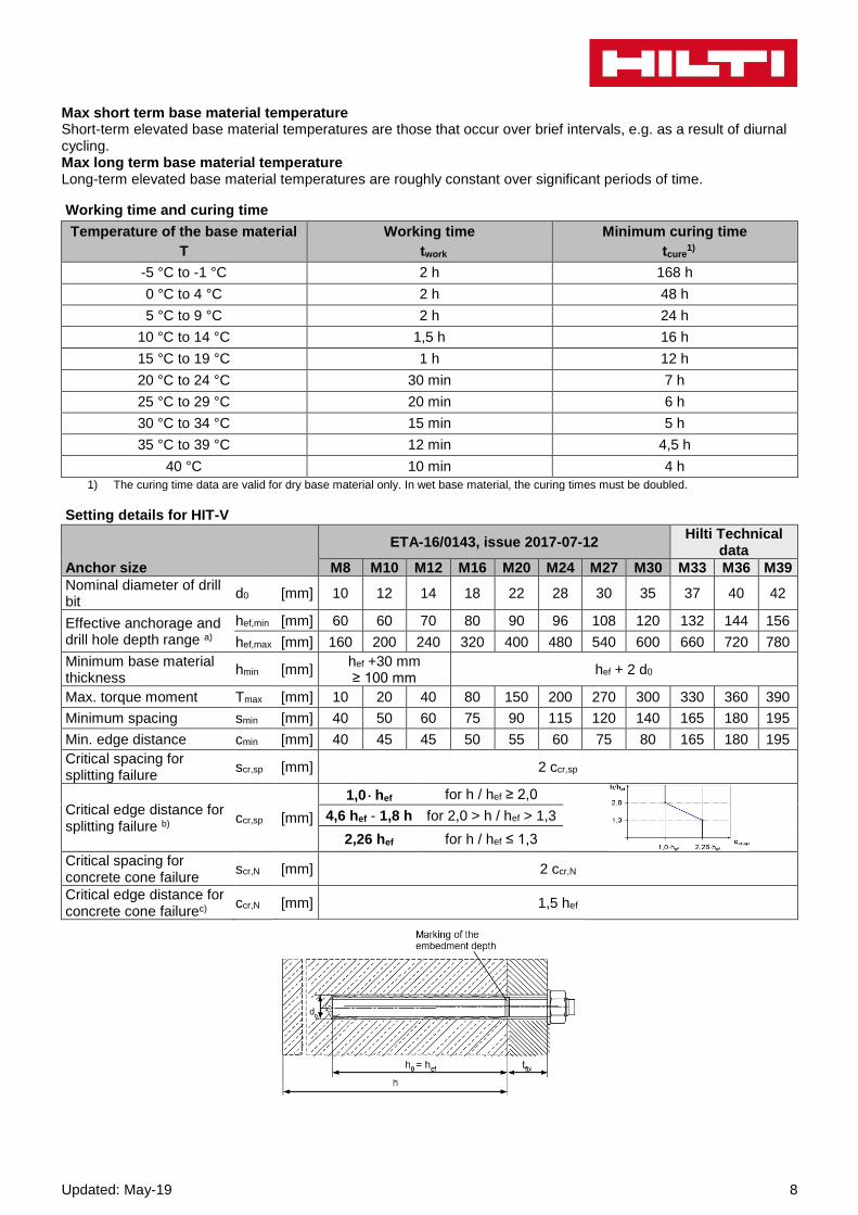
Setting details for HIT-V
Anchor size
ETA-16/0143, issue 2017-07-12 Hilti Technical
data
M8 M10 M12 M16 M20 M24 M27 M30 M33 M36 M39
Nominal diameter of drill bit
d0 [mm] 10 12 14 18 22 28 30 35 37 40 42
Effective anchorage and drill hole depth range a)
hef,min [mm] 60 60 70 80 90 96 108 120 132 144 156
hef,max [mm] 160 200 240 320 400 480 540 600 660 720 780
Minimum base material thickness
hmin [mm] hef +30 mm ≥ 100 mm
hef + 2 d0
Max. torque moment Tmax [mm] 10 20 40 80 150 200 270 300 330 360 390
Minimum spacing smin [mm] 40 50 60 75 90 115 120 140 165 180 195
Min. edge distance cmin [mm] 40 45 45 50 55 60 75 80 165 180 195
Critical spacing for splitting failure
scr,sp [mm] 2 ccr,sp
Critical edge distance for splitting failure b)
ccr,sp [mm]
1,0 hef for h / hef ≥ 2,0
4,6 hef - 1,8 h for 2,0 > h / hef > 1,3
2,26 hef for h / hef ≤ 1,3
Critical spacing for concrete cone failure
scr,N [mm] 2 ccr,N
Critical edge distance for concrete cone failurec)
ccr,N [mm] 1,5 hef

9 Updated: May-19
Setting details for HIS-N
Anchor size M8 M10 M12 M16 M20
Nominal diameter of drill bit
d0 [mm] 14 18 22 28 32
Diameter of element d [mm] 12,5 16,5 20,5 25,4 27,6
Effective anchorage and drill hole depth
hef [mm] 90 110 125 170 205
Minimum base material thickness
hmin [mm] 120 150 170 230 270
Diameter of clearance hole in the fixture
df [mm] 9 12 14 18 22
Thread engagement length; min - max
hs [mm] 8-20 10-25 12-30 16-40 20-50
Minimum spacing smin [mm] 60 70 90 115 130
Minimum edge distance cmin [mm] 40 45 55 65 90
Critical spacing for splitting failure
scr,sp [mm] 2 ccr,sp
Critical edge distance for splitting failure b)
ccr,sp [mm]
1,0 hef for h / hef ≥ 2,0
4,6 hef – 1,8 h for 2,0 > h / hef > 1,3
2,26 hef for h / hef ≤ 1,3
Critical spacing for concrete cone failure
scr,N [mm] 2 ccr,N
Critical edge distance for concrete cone failure c)
ccr,N [mm] 1,5 hef
Max. torque moment a) Tmax [Nm] 10 20 40 80 150 For spacing (edge distance) smaller than critical spacing (critical edge distance) the design loads have to be reduced. a) hef,min ≤ hef ≤ hef,max (hef: embedment depth) b) h: base material thickness (h ≥ hmin) c) The critical edge distance for concrete cone failure depends on the embedment depth hef and the design bond
resistance. The simplified formula given in this table is on the save side.
Installation equipment Anchor size M8 M10 M12 M16 M20 M24 M27 M30 M36 M39
Rotary hammer HIT-V TE 2 – TE 16 TE 40 – TE 80
Not available
from Hilti
HIS-N TE 2 – TE 16 TE 40 – TE 80 -
Other tools compressed air gun, set of cleaning brushes, dispenser
roughening tools TE-YRT -
Additional
Hilti recommended tools DD EC-1, DD 100 … DD 160 a) -
a) For anchors in diamond drilled holes load values for combined pull-out and concrete cone resistance have to be reduced

Updated: May-19 10
Minimum roughening time troughen (troughen [sec] = hef [mm] /10 )
hef [mm] troughen [sec]
0 to 100 10
101 to 200 20
201 to 300 30
301 to 400 40
401 to 500 50
501 to 600 60
Parameters of cleaning and setting tools
HIT-V HIS-N
Drill bit diameters d0 [mm] Installation
Hammer drill (HD)
Hollow Drill Bit (HDB)
Diamond coring
Brush HIT-RB
Piston plug HIT-SZ
Diamond coring (DD)
With roughening tool (RT)
M8 - 10 - 10 - 10 -
M10 - 12 - 12 - 12 12
M12 M8 14 14 14 - 14 14
M16 M10 18 18 18 18 18 18
M20 M12 22 22 22 22 22 22
M24 M16 28 28 28 28 28 28
M27 - 30 - 30 30 30 30
- M20 32 32 32 32 32 32
M30 - 35 35 35 35 35 35
M33 - 37 - - - 37 37
M36 - 40 - - - 40 40
M39 - 42 - - - 42 42
Associated components for the use of Hilti Roughening tool TE-YRT Diamond coring Roughening tool TE-YRT Wear gauge RTG…
d0 [mm]
d0 [mm] size Nominal measured
18 17,9 to 18,2 18 18
20 19,9 to 20,2 20 20
22 21,9 to 22,2 22 22
25 24,9 to 25,2 25 25
28 27,9 to 28,2 28 28
30 29,9 to 30,2 30 30
32 31,9 to 32,2 32 32
35 34,9 to 35,2 35 35

11 Updated: May-19
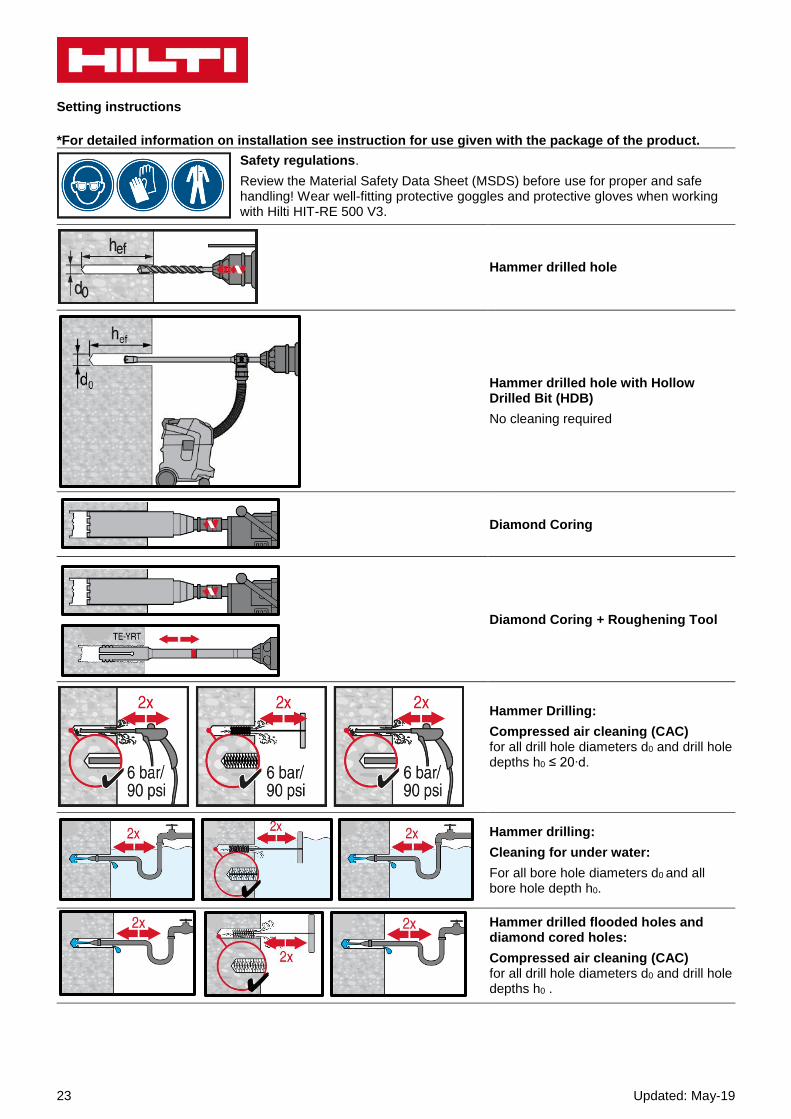
Setting instructions
*For detailed information on installation see instruction for use given with the package of the product.
Safety regulations.
Review the Material Safety Data Sheet (MSDS) before use for proper and safe handling! Wear well-fitting protective goggles and protective gloves when working with Hilti HIT-RE 500 V3.
Drilling
Hammer drilled hole
For dry and wet concrete and installation in flooded holes (no sea water).
Hammer drilled hole with Hollow Drilled Bit (HDB)
No cleaning required. For dry and wet concrete, only.
Diamond Coring For dry and wet concrete, only.
Diamond Coring + Roughening Tool For dry and wet concrete only. Before roughening, the borehole needs to be dry.
Cleaning ( Inadequate hole cleaning=poor load values.)
Hammer Drilling:
Compressed air cleaning (CAC) For all drill hole diameters d0 and all drill hole depths h0.
Hammer drilling:
Cleaning for under water:
For all bore hole diameters d0 and all bore hole depth h0.
Updated: May-19 12
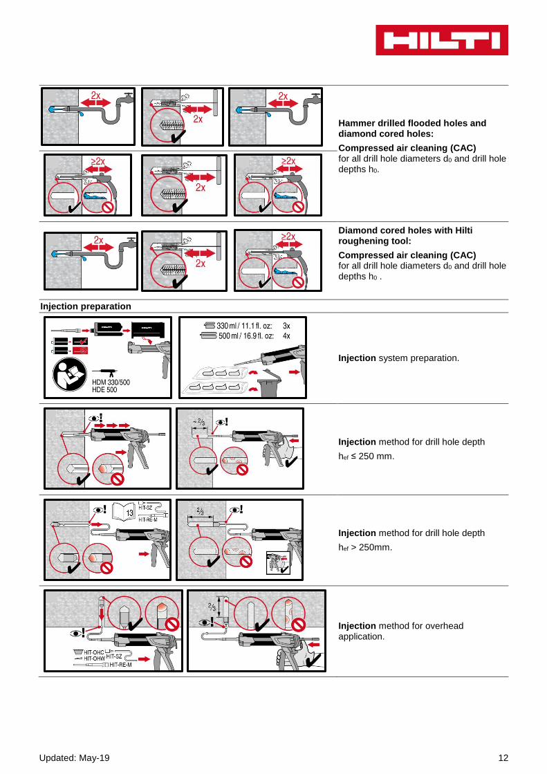
Hammer drilled flooded holes and diamond cored holes:
Compressed air cleaning (CAC) for all drill hole diameters d0 and drill hole depths h0.
Diamond cored holes with Hilti roughening tool:
Compressed air cleaning (CAC) for all drill hole diameters d0 and drill hole depths h0 .
Injection preparation
Injection system preparation.
Injection method for drill hole depth
hef ≤ 250 mm.
Injection method for drill hole depth
hef > 250mm.
Injection method for overhead application.
13 Updated: May-19
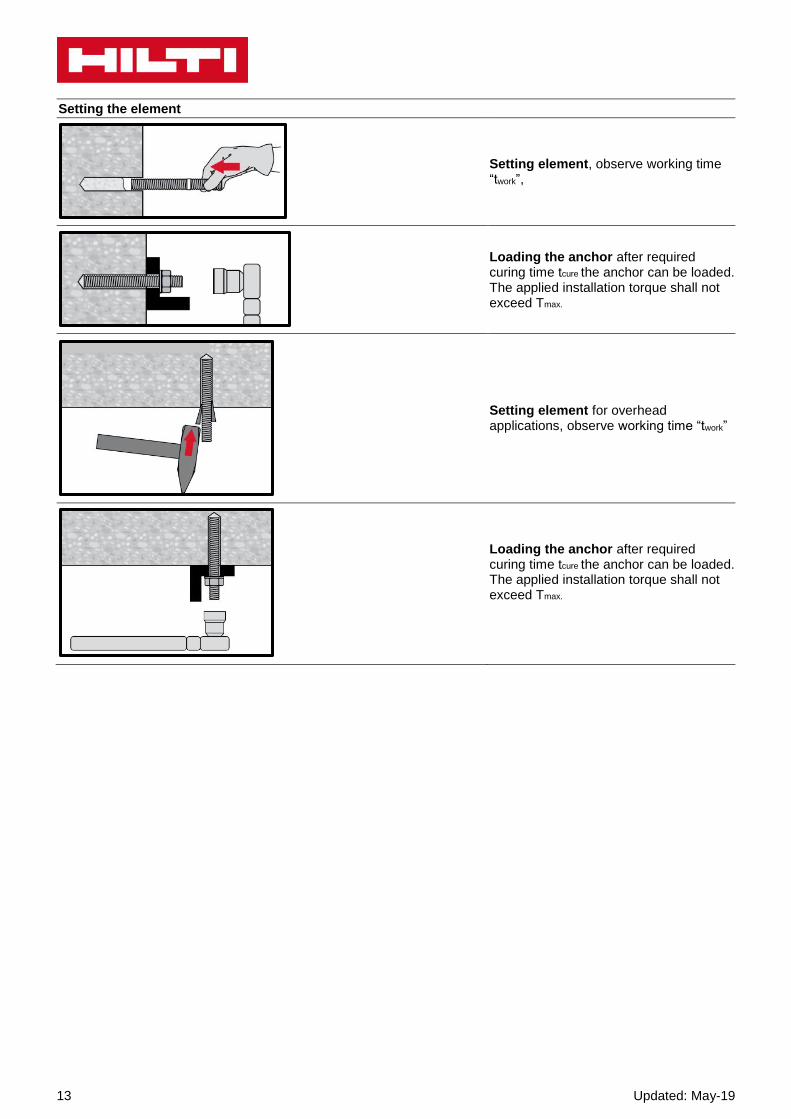
Setting the element
Setting element, observe working time “twork”,
Loading the anchor after required curing time tcure the anchor can be loaded. The applied installation torque shall not exceed Tmax.
Setting element for overhead applications, observe working time “twork”
Loading the anchor after required curing time tcure the anchor can be loaded. The applied installation torque shall not exceed Tmax.

Updated: May-19 14

15 Updated: May-19
HIT-RE 500 V3 injection mortar Anchor design (ETAG 001) / Rebar elements / Concrete
Injection mortar system Benefits
Hilti
HIT-RE 500 V3
500 ml foil pack
(also available as
330 ml and 1400
ml foil pack)
- SafeSet technology: Simplified
method of borehole preparation
using either Hilti hollow drill bit for
hammer drilling or Roughening tool
for diamond cored applications
- Suitable for non-cracked and
cracked concrete C 20/25 to
C 50/60
- ETA approval for seismic
performance category C1
- Hilti Technical Data for seismic
performance category C2
- High loading capacity
- Suitable for dry and water saturated
concrete
- Hilti Technical Data for under water
application
- Fastest curing epoxy mortar to
speed up construction process
- Long working time to allow
installation of big diameters and/or
deep embedment depths even at
higher temperature
- Cures down to -5°C
Rebar B500 B
(8 - 40)
Base material Load conditions
Concrete (non-
cracked)
Concrete (cracked)
Dry concrete Wet concrete
Static/ quasi-static
Seismic, ETA-C1
Hilti Technical Data-C2
Installation conditions Other informations
Hammer drilling
Diamond coring
Hilti SafeSet technology
Small edge distance and
spacing
European Technical
Assessment
CE conformity
PROFIS Rebar design
Software
a) All data given in this section according to ETA-16/0143 issue 2016-11-30.
Approvals / certificates
Description Authority / Laboratory No. / date of issue
European technical assessment a) CSTB, Marne la Vallée ETA-16/0143 / 2017-07-12

Updated: May-19 16
Static and quasi-static loading (for a single anchor) All data in this section applies to -Design according to TR029 -Correct setting (See setting instruction) -No edge distance and spacing influence -Steel failure -Base material thickness, as specified in the table -One typical embedment depth, as specified in the table -Rebar B500B -Concrete C 20/25, fck,cube = 25 N/mm² -Temperate range I (min. base material temp. -40°C, max. long term/short term base material temp.: +24°C/40°C)
For hammer drilled holes, hollow drill bit1) and diamond cored with roughening tool2): 1) Hilti hollow drill bit available for element size 12-28.
2) Roughening tools are available for element size 14-28.
1) Hilti hollow drill bit available for element size 12-28.
2) Roughening tools are available for element size 14-28.
1) Hilti hollow drill bit available for element size 12-28.
2) Roughening tools are available for element size 14-28.
Embedment depth and base material thickness for static and quasi-static loading data
Anchor- size
ETA-16/0143, issue 2017-07-12 Hilti
technical data
8 10 12 14 16 20 25 28 30 32 36 40
Typ. embedment depth [mm] 80 90 110 125 125 170 210 270 285 300 330 360
Base material thickness [mm] 110 120 140 161 165 220 274 340 359 380 420 470
Characteristic resistance
Anchor- size
ETA-16/0143, issue 2017-07-12 Hilti
technical data
8 10 12 14 16 20 25 28 30 32 36 40
Non-cracked concrete
Tensile NRk B500B [kN]
- 39,6 58,1 70,6 70,6 111,9 153,7 224,0 249,4 262,4 302,7 344,9
Shear VRk B500B - 22,0 31,0 42,0 55,0 86,0 135,0 169,0 194,0 221,0 280,0 346,0
Cracked concrete
Tensile NRk B500B [kN]
- 24,0 39,4 50,3 50,3 79,8 109,6 159,7 177,8 187,1 - -
Shear VRk B500B - 22,0 31,0 42,0 55,0 86,0 135,0 169,0 194,0 221,0 - -
Design resistance
Anchor- size
ETA-16/0143, issue 2017-07-12 Hilti
technical data
8 10 12 14 16 20 25 28 30 32 36 40
Non-cracked concrete
Tensile NRd B500B [kN]
- 26,4 38,7 47,1 47,1 74,6 102,5 149,4 166,3 174,9 168,2 191,6
Shear VRd B500B - 14,7 20,7 28,0 36,7 57,3 90,0 112,7 129,3 147,3 186,7 230,7
Cracked concrete
Tensile NRd B500B [kN]
- 16,0 26,3 33,5 33,5 53,2 73,0 106,5 118,5 124,7 - -
Shear VRd B500B - 14,7 20,7 28,0 36,7 57,3 90,0 112,7 129,3 147,3 - -

17 Updated: May-19
1) Hilti hollow drill bit available for element size 12-28.
2) Roughening tools are available for element size 14-28.
3) With overall partial safety factor for action γ=1,4. The partial safety factors for action depend on the type of loading and shall be taken
from national regulations.
For diamond cored holes:
a) With overall partial safety factor for action γ=1,4. The partial safety factors for action depend on the type of loading and shall be taken
from national regulations.
Recommended loads3)
Anchor- size
ETA-16/0143, issue 2017-07-12 Hilti
technical data
8 10 12 14 16 20 25 28 30 32 36 40
Non-cracked concrete
Tensile NRec B500B [kN]
- 18,8 27,6 33,6 33,6 53,3 73,2 106,7 115,7 125,0 120,1 136,9
Shear VRec B500B - 10,5 14,8 20,0 26,2 41,0 64,3 80,5 92,4 105,2 133,3 164,6
Cracked concrete
Tensile NRec B500B [kN]
- 11,4 18,8 24,0 24,0 38,0 52,2 76,1 84,7 89,1 - -
Shear VRec B500B - 10,5 14,8 20,0 26,2 41,0 64,3 80,5 92,4 105,2 - -
Characteristic resistance
Anchor- size
ETA-16/0143, issue 2017-07-12
8 10 12 14 16 20 25 28 30 32
Tensile NRk B500B [kN]
- 25,4 37,3 49,5 56,5 96,1 148,4 224,0 249,4 262,4
Shear VRk B500B - 22,0 31,0 42,0 55,0 86,0 135,0 169,0 194,0 221,0
Design resistance
Anchor- size
ETA-16/0143, issue 2017-07-12
8 10 12 14 16 20 25 28 30 32
Tensile NRd B500B [kN]
- 14,1 20,7 27,5 26,9 45,8 70,7 106,7 115,7 125,0
Shear VRd B500B - 14,7 20,7 28,0 36,7 57,3 90,0 112,7 129,3 147,3
Recommended loadsa)
Anchor- size
ETA-16/0143, issue 2017-07-12
8 10 12 14 16 20 25 28 30 32
Tensile NRec B500B [kN]
- 10,1 14,8 19,6 19,2 32,7 50,5 76,2 82,6 89,3
Shear VRec B500B - 10,5 14,8 20,0 26,2 41,0 64,3 80,5 92,4 105,2

Updated: May-19 18
Seismic loading (for a single anchor) All data in this section applies to: - Design according to TR 045 - Correct setting (See setting) - No edge distance and spacing influence - Steel failure - Minimum base material thickness - Concrete C 20/25, fck,cube = 25 N/mm² - Rebar B450C -Temperate range I (min. base material temperature -40°C, max. long term/short term base material temperature: +24°C/40°C) - Installation temperature range -5°C to +40°C - αgap = 1,0
For hammer drilled holes:
1) Hilti technical data.
1) Hilti technical data.
For hammer drilled holes, hollow drill bit2) and diamond cored with roughening tool3):
1) Hilti hollow drill bit available for element size 12-28.
2) Roughening tools are available for element size 14-28.
2) Hilti hollow drill bit available for element size 12-28.
3) Roughening tools are available for element size 14-28.
Embedment depth and base material thickness in case of seismic performance category C2
Anchor- size 8 10 12 14 16 20 25 28 30 32 36 40
Typical embedment depth [mm] - - - - 125 170 210 - - - - -
Base material thickness [mm] - - - - 165 220 274 - - - - -
Characteristic resistance in case of seismic performance category C21)
Anchor- size 8 10 12 14 16 20 25 28 30 32 36 40
Tensile NRk, seis B450C [kN] - - - - 24,5 45,9 57,7 - - - - -
Shear VRk, seis B450C [kN] - - - - 16,7 29,7 40,7 - - - - -
Design resistance in case of seismic performance category C21)
Anchor- size 8 10 12 14 16 20 25 28 30 32 36 40
Tensile NRd, seis B450C [kN] - - - - 16,3 30,6 38,5 - - - - -
Shear VRd, seis B450C [kN] - - - - 13,3 23,7 32,5 - - - - -
Embedment depth and base material thickness in case of seismic performance category C1
Anchor- size 8 10 12 14 16 20 25 28 30 32 36 40
Typical embedment depth [mm] - 90 110 125 125 170 210 270 285 300 - -
Base material thickness [mm] - 120 140 161 165 220 274 340 359 380 - -
Characteristic resistance in case of seismic performance category C1
Anchor- size 8 10 12 14 16 20 25 28 30 32 36 40
Tensile NRk, seis B500B [kN]
- 22,6 35,3 42,8 42,8 67,8 93,1 135,8 151,1 159,0 - -
Shear VRk, seis B500B - 22,0 31,0 42,0 55,0 86,0 135,0 169,0 194,0 221,0 - -
Design resistance in case of seismic performance category C1
Anchor- size 8 10 12 14 16 20 25 28 30 32 36 40
Tensile NRd, seis B500B [kN]
- 15,1 23,5 28,5 28,5 45,2 62,1 90,5 100,7 106,0 - -
Shear VRd, seis B500B - 14,7 20,7 28,0 36,7 57,3 90,0 112,7 129,3 147,3 - -

19 Updated: May-19
Materials
Material quality
Part Material
Rebar EN 1992-1-1:2004 and AC:2010
Bars and de-coiled rods class B or C with fyk and k according to NDP or NCL of EN 1992-1-1/ NA:2013 fuk = ftk = k · fyk
Setting information
Installation temperature range: -5°C to +40°C Service temperature range Hilti HIT-RE 500 V3 injection mortar may be applied in the temperature ranges given below. An elevated base material temperature may lead to a reduction of the design bond resistance.
Temperature range Base material temperature
Max. long term base material temperature
Max. short term base material temperature
Temperature range I -40 °C to + 40 °C + 24 °C + 40 °C
Temperature range II -40 °C to + 70 °C + 43 °C + 70 °C
Max. short term base material temperature Short term elevated base material temperatures are those that occur over brief intervals, e.g. as a result of diurnal cycling. Max. long term base material temperature Long term elevated base material temperatures are roughly constant over significant periods of time.
Working time and curing time
Temperature of the
base material
Max. working time in which rebar can be inserted and adjusted tgel
Min. curing time before rebar can be fully loaded tcure
1)
-5 °C TBM -1 °C 2 h 168 h
0 °C TBM 4 °C 2 h 48 h
5 °C TBM 9 °C 2 h 24 h
10 °C TBM 14 °C 1,5 h 16 h
15 °C TBM 19 °C 1 h 12 h
20 °C TBM 24 °C 30 min 7 h
25 °C TBM 29 °C 20 min 6 h
30 °C TBM 34 °C 15 min 5 h
35 °C TBM 39 °C 12 min 4,5 h
TBM = 40 °C 10 min 4 h 1) The curing time data are valid for dry base material only. In wet base material the curing times must be doubled.
Mechanical properties
Anchor size
8 10 12 14 16 20 25 28 30 32 36 40
Nominal tensile strength fuk
B500B [N/mm²]
550 550 550 550 550 550 550 550 550 550 550 550
B450C - - - - 518 518 518 - - - - -
Yield strength fyk
B500B [N/mm²]
500 500 500 500 500 500 500 500 500 500 500 500
B450C - - - - 450 450 450 - - - - -
Stressed cross-section As
B500B [mm²]
50,3 78,5 113,1 153,9 201,1 314,2 490,9 615,8 706,9 804,2 1018 1257
B450C - - - - 201,1 314,2 490,9 - - - - -
Moment of resistance W
B500B [mm³]
50,3 98,2 169,6 269,4 402,1 785,4 1534 2155 2650 3217 4580 6283
B450C - - - - 402,1 785,4 1534 - - - - -

Updated: May-19 20
Installation equipment
Rebar – size 8 10 12 14 16 20 25 28 30 32 36 40
Rotary hammer TE 2 (-A) – TE 40(-A) TE40 – TE80
Diamond coring tools DD EC-1, DD 100 … DD 160 a) -
Other tools Compressed air gun,brush, hollow drill bit,
roughening tool, dispenser, piston plug
a) For anchors in diamond drilled holes, load values for combined pull-out and concrete cone resistance have to be reduced (see section “Setting instruction”)
Associated components for the use of Hilti Roughening tool TE-YRT Diamond coring Roughening tool TE-YRT Wear gauge RTG…
d0 [mm]
d0 [mm] size Nominal measured
18 17,9 to 18,2 18 18
20 19,9 to 20,2 20 20
22 21,9 to 22,2 22 22
25 24,9 to 25,2 25 25
28 27,9 to 28,2 28 28
30 29,9 to 30,2 30 30
32 31,9 to 32,2 32 32
35 34,9 to 35,2 35 35
Minimum roughening time troughen (troughen [sec] = hef [mm] /10 )
hef [mm] troughen [sec]
0 to 100 10
101 to 200 20
201 to 300 30
301 to 400 40
401 to 500 50
501 to 600 60

21 Updated: May-19
Setting details
Anchor size Ø8 Ø10 Ø12 Ø14 Ø16 Ø20 Ø25 Ø28 Ø30 Ø32 Ø36 Ø40
Nominal diameter
of drill bit d0 [mm]
10 12 a)
12 14a)
14a) 16a) 18 20 25 30 32a) 35 37 40 451) 551)
Effective
anchorage and
drill hole depth
range b)
hef,min [mm] 60 60 70 70 75 80 90 100 112 120 128 1441) 1601)
hef,max [mm] 160 200 240 240 280 320 400 500 560 600 640 7201) 8001)
Minimum base
material
thickness
hmin [mm] hef +30mm ≥ 100 mm
hef + 2 d0
Minimum spacing smin [mm] 40 50 60 60 70 80 100 125 140 150 160 1801) 2001)
Minimum edge
distance
cmin [mm] 40 45 45 45 50 50 65 70 75 80 80 1801) 2001)
Critical spacing
for splitting failure scr,sp [mm] 2 ccr,sp
Critical edge
distance for
splitting failure c)
ccr,sp [mm]
1,0 hef for h / hef ≥ 2,0
4,6 hef - 1,8 h for 2,0 > h / hef > 1,3
2,26 hef for h / hef ≤ 1,3
Critical spacing
for concrete cone
failure
scr,N [mm] 2 ccr,N
Critical edge
distance for
concrete cone
failure d)
ccr,N [mm] 1,5 hef
1) Additional Hilti Technical data For spacing (edge distance) smaller than critical spacing (critical edge distance) the design loads have to be reduced. a) both given values for drill bit diameter can be used b) hef,min ≤ hef ≤ hef,max (hef: embedment depth) c) h: base material thickness (h ≥ hmin) d) The critical edge distance for concrete cone failure depends on the embedment depth hef and the
design bond resistance. The simplified formula given in this table is on the save side

Updated: May-19 22
Drilling and cleaning diameters
Rebar - size
Hammer drill (HD)
Hollow Drill Bit (HDB)
Diamond coring
Brush HIT-RB
Piston plug HIT-SZ
Diamond coring (DD)
With roughening
tool (RT)
d0 [mm] size [mm]
8 12 (10 a)) - 12 (10 a)) - 12 (10 a)) 12
10 14 (12 a)) 14 14 (12 a)) - 14 (12 a)) 14 (12 a))
12 16 (14 a)) 16 (14 a)) 16 (14 a)) - 16 (14 a)) 16 (14 a))
14 18 18 18 18 18 18
16 20 20 20 20 20 20
20 25 25 25 25 25 25
25 32 32 32 32 32 32
28 35 35 35 35 35 35
30 37 - 37 - 37 37
32 40 - - - 40 40
- - 42 - 42 42
36 45b) - - - 45b) 45b)
40 55b) - - - 55b) 55b) a) Each of two given values can be used b) Additional Hilti technical data
23 Updated: May-19
Setting instructions
*For detailed information on installation see instruction for use given with the package of the product.
Safety regulations.
Review the Material Safety Data Sheet (MSDS) before use for proper and safe handling! Wear well-fitting protective goggles and protective gloves when working with Hilti HIT-RE 500 V3.
Hammer drilled hole
Hammer drilled hole with Hollow Drilled Bit (HDB)
No cleaning required
Diamond Coring
Diamond Coring + Roughening Tool
Hammer Drilling:
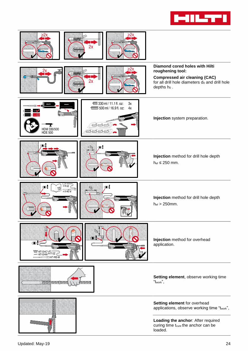
Compressed air cleaning (CAC) for all drill hole diameters d0 and drill hole depths h0 ≤ 20∙d.
Hammer drilling:
Cleaning for under water:
For all bore hole diameters d0 and all bore hole depth h0.
Hammer drilled flooded holes and diamond cored holes:
Compressed air cleaning (CAC) for all drill hole diameters d0 and drill hole depths h0 .
Updated: May-19 24
Diamond cored holes with Hilti roughening tool:
Compressed air cleaning (CAC) for all drill hole diameters d0 and drill hole depths h0 .
Injection system preparation.
Injection method for drill hole depth
hef ≤ 250 mm.
Injection method for drill hole depth
hef > 250mm.
Injection method for overhead application.
Setting element, observe working time “twork”,
Setting element for overhead applications, observe working time “twork”,
Loading the anchor: After required curing time tcure the anchor can be loaded.
25 Updated: May-19
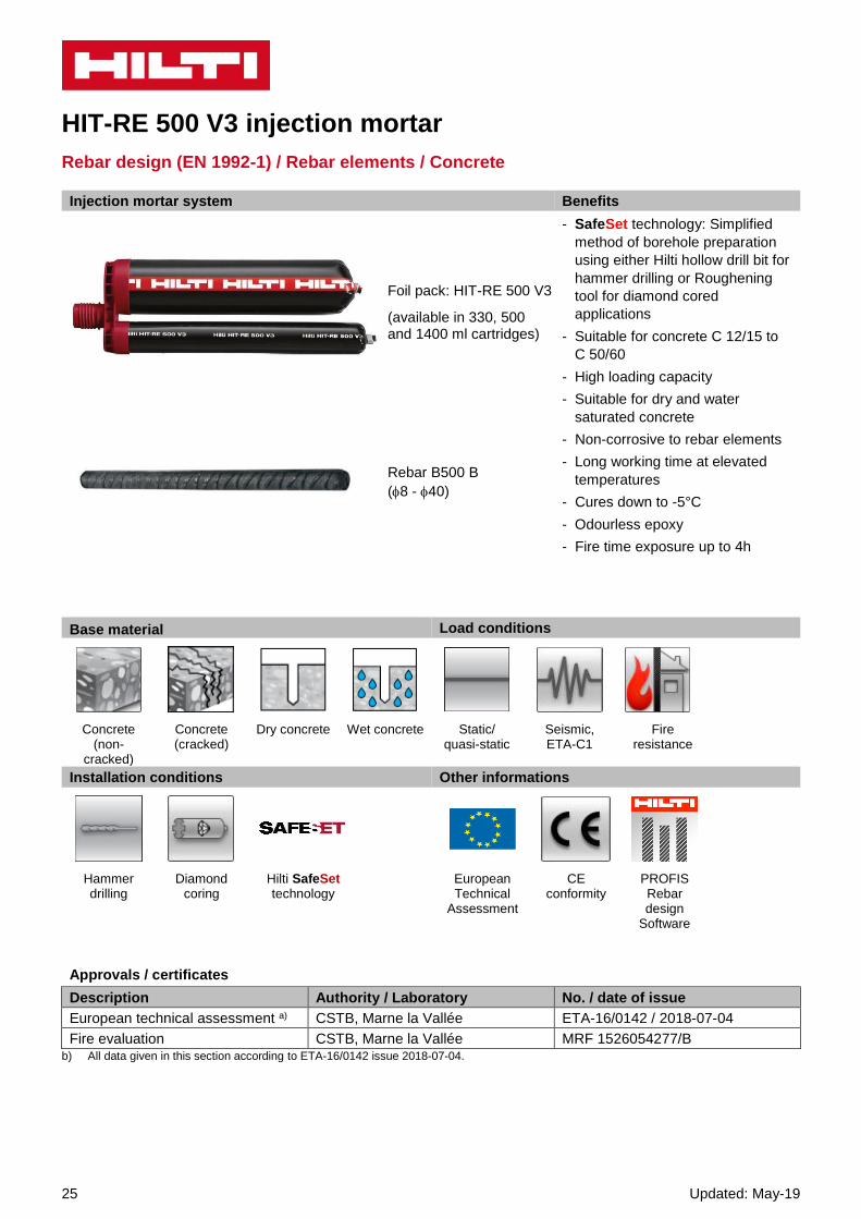
HIT-RE 500 V3 injection mortar
Rebar design (EN 1992-1) / Rebar elements / Concrete
Injection mortar system Benefits
Foil pack: HIT-RE 500 V3
(available in 330, 500 and 1400 ml cartridges)
- SafeSet technology: Simplified
method of borehole preparation
using either Hilti hollow drill bit for
hammer drilling or Roughening
tool for diamond cored
applications
- Suitable for concrete C 12/15 to
C 50/60
- High loading capacity
- Suitable for dry and water
saturated concrete
- Non-corrosive to rebar elements
- Long working time at elevated
temperatures
- Cures down to -5°C
- Odourless epoxy
- Fire time exposure up to 4h
Rebar B500 B
(8 - 40)
Base material Load conditions
Concrete (non-
cracked)
Concrete (cracked)
Dry concrete Wet concrete Static/ quasi-static
Seismic, ETA-C1
Fire resistance
Installation conditions Other informations
Hammer drilling
Diamond coring
Hilti SafeSet technology
European Technical
Assessment
CE conformity
PROFIS Rebar design
Software
b) All data given in this section according to ETA-16/0142 issue 2018-07-04.
Approvals / certificates
Description Authority / Laboratory No. / date of issue
European technical assessment a) CSTB, Marne la Vallée ETA-16/0142 / 2018-07-04
Fire evaluation CSTB, Marne la Vallée MRF 1526054277/B
Updated: May-19 26
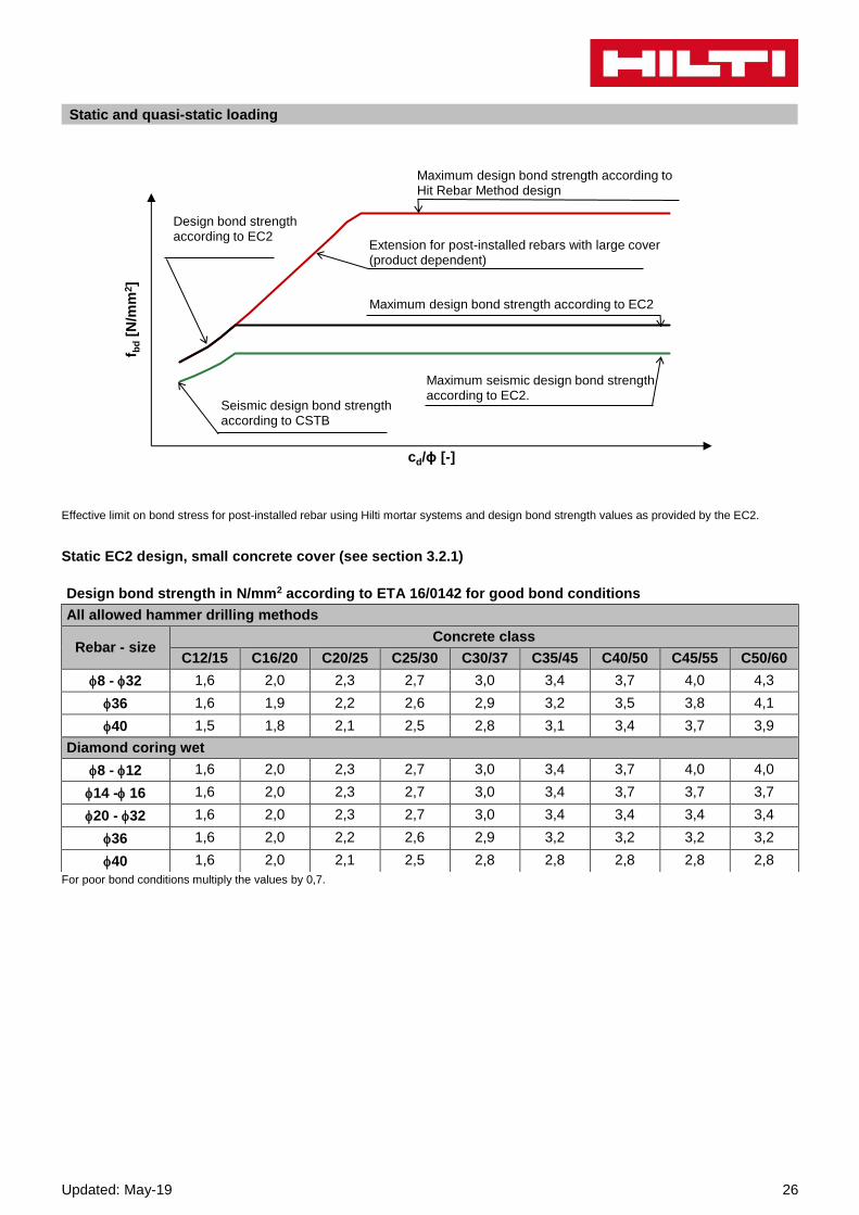
Static and quasi-static loading
Effective limit on bond stress for post-installed rebar using Hilti mortar systems and design bond strength values as provided by the EC2.
Static EC2 design, small concrete cover (see section 3.2.1)
For poor bond conditions multiply the values by 0,7.
f bd
[N/m
m2]
cd/ϕ [-]
Maximum design bond strength according to Hit Rebar Method design
Maximum design bond strength according to EC2
Design bond strength according to EC2
Extension for post-installed rebars with large cover (product dependent)
Seismic design bond strength according to CSTB
Maximum seismic design bond strength according to EC2.
Design bond strength in N/mm2 according to ETA 16/0142 for good bond conditions
All allowed hammer drilling methods
Rebar - size
Concrete class
C12/15 C16/20 C20/25 C25/30 C30/37 C35/45 C40/50 C45/55 C50/60
8 - 32 1,6 2,0 2,3 2,7 3,0 3,4 3,7 4,0 4,3
36 1,6 1,9 2,2 2,6 2,9 3,2 3,5 3,8 4,1
40 1,5 1,8 2,1 2,5 2,8 3,1 3,4 3,7 3,9
Diamond coring wet
8 - 12 1,6 2,0 2,3 2,7 3,0 3,4 3,7 4,0 4,0
14 - 16 1,6 2,0 2,3 2,7 3,0 3,4 3,7 3,7 3,7
20 - 32 1,6 2,0 2,3 2,7 3,0 3,4 3,4 3,4 3,4
36 1,6 2,0 2,2 2,6 2,9 3,2 3,2 3,2 3,2
40 1,6 2,0 2,1 2,5 2,8 2,8 2,8 2,8 2,8

27 Updated: May-19
Static Hit Rebar design method, large concrete cover (see section 3.2.2)
Pullout design bond strength [fbd,po = τRk/γMp] in N/mm² for good bond conditions
Non-cracked concrete C20/25, all allowed drilling methods
Temperature range
Drilling method Rebar - size
8 10 12 14 16 20 25 28 30 32 36 40
I: 40°C/24° C
Hammer drilled holes 6,3 9,5 9,5 9,5 9,5 9,5 8,7 8,7 8,7 8,7 6,7 7,9
Hammer drilled holes with hollow drill bit
- - 9,5 9,5 9,5 9,5 8,7 8,7 - - - -
Diamond cored holes with roughening tool
- - - 9,5 9,5 9,5 8,7 8,7 - - - -
Diamond cored holes 5 5 5 5 5 5 5 5,3 5,3 5,3 - -
Hammer drilled holes in water filled holes
3,8 5,7 5,7 5,7 5,7 5,7 5,2 5,2 5,2 5,2 - -
II: 70°C/43° C
Hammer drilled holes 4,7 7,3 7,3 7,3 6,7 6,7 6,7 6,3 6,3 6,3 5,7 5,0
Hammer drilled holes with hollow drill bit
- - 7,3 7,3 6,7 6,7 6,7 6,3 - - - -
Diamond cored holes with roughening tool
- - - 7,3 6,7 6,7 6,7 6,3 - - - -
Diamond cored holes 3,6 3,6 3,6 3,6 3,1 3,3 3,3 3,3 3,3 3,3 - -
Hammer drilled holes in water filled holes
2,6 4,3 4,3 4,3 4,3 4,0 4,0 4,0 3,8 3,8 - -
Cracked concrete C20/25, all allowed drilling methods
I: 40°C/24° C
Hammer drilled holes 3 5,7 6,3 6,3 6,3 6,7 6,7 7,3 7,3 7,3
Hammer drilled holes with hollow drill bit
- - 6,3 6,3 6,3 6,7 6,7 7,3 - - - -
Diamond cored holes with roughening tool
- - - 6,3 6,3 6,7 6,7 7,3 - - - -
II: 70°C/43° C
Hammer drilled holes 2,7 4,7 5,3 5,3 5,3 5,3 5,3 5,3 5,3 5,3
Hammer drilled holes with hollow drill bit
- - 5,3 5,3 5,3 5,3 5,3 - - - -
Diamond cored holes with roughening tool
- - - 5,3 5,3 5,3 5,3 5,3 - - - -
For poor bond conditions multiply values by 0,7.
Increasing factors in concrete for fbd,po
Dilling method Concrete
class
Rebar-size
8 10 12 14 16 20 25 28 30 32 36 40
Hammer drilled holes
Hammer drilled holes with hollow drill bit
Diamond cored holes
C 30/37 1,04
C40/50 1,07
C50/60 1,09
Diamond cored holes with roughening tool
C 30/37 - C50/60
1,0 -
Updated: May-19 28
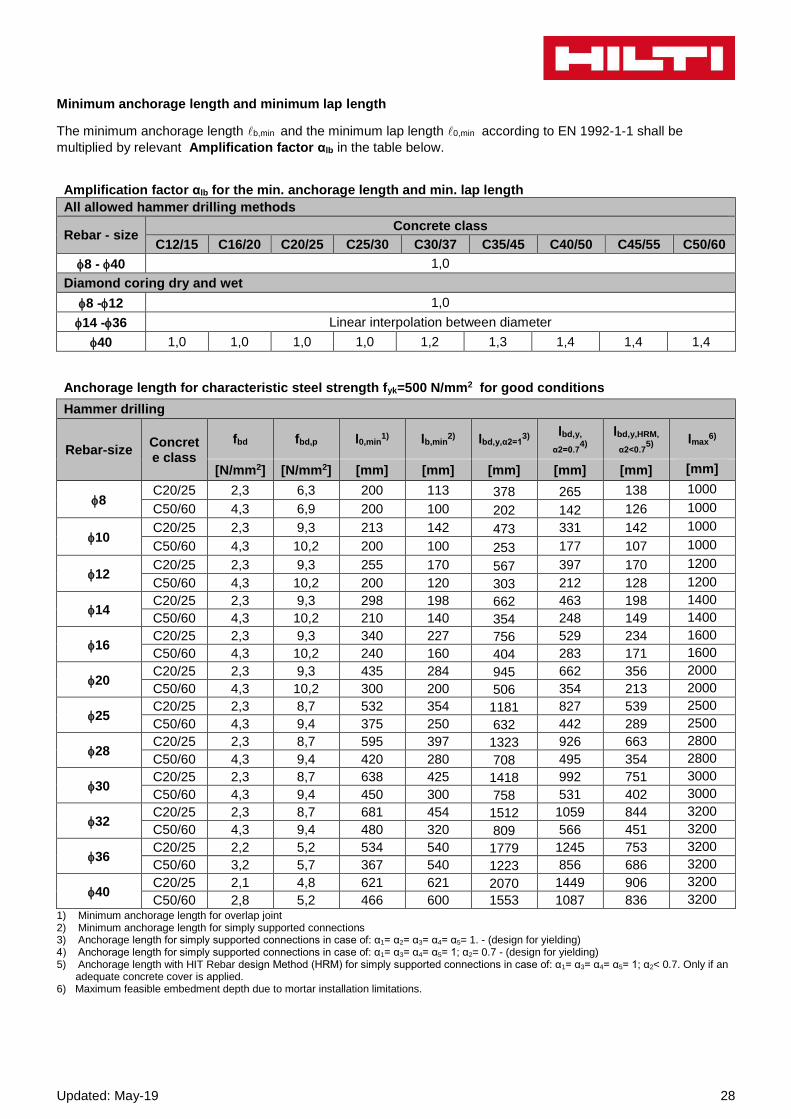
Minimum anchorage length and minimum lap length
The minimum anchorage length b,min and the minimum lap length 0,min according to EN 1992-1-1 shall be
multiplied by relevant Amplification factor αlb in the table below.
Amplification factor αlb for the min. anchorage length and min. lap length
All allowed hammer drilling methods
Rebar - size Concrete class
C12/15 C16/20 C20/25 C25/30 C30/37 C35/45 C40/50 C45/55 C50/60
8 - 40 1,0
Diamond coring dry and wet
8 -12 1,0
14 -36 Linear interpolation between diameter
40 1,0 1,0 1,0 1,0 1,2 1,3 1,4 1,4 1,4
Anchorage length for characteristic steel strength fyk=500 N/mm2 for good conditions
Hammer drilling
Rebar-size Concrete class
fbd fbd,p l0,min1) lb,min
2) lbd,y,α2=13)
lbd,y,
α2=0.74)
lbd,y,HRM,
α2<0.75)
lmax6)
[N/mm2] [N/mm2] [mm] [mm] [mm] [mm] [mm] [mm]
8 C20/25 2,3 6,3 200 113 378 265 138 1000
C50/60 4,3 6,9 200 100 202 142 126 1000
10 C20/25 2,3 9,3 213 142 473 331 142 1000
C50/60 4,3 10,2 200 100 253 177 107 1000
12 C20/25 2,3 9,3 255 170 567 397 170 1200
C50/60 4,3 10,2 200 120 303 212 128 1200
14 C20/25 2,3 9,3 298 198 662 463 198 1400
C50/60 4,3 10,2 210 140 354 248 149 1400
16 C20/25 2,3 9,3 340 227 756 529 234 1600
C50/60 4,3 10,2 240 160 404 283 171 1600
20 C20/25 2,3 9,3 435 284 945 662 356 2000
C50/60 4,3 10,2 300 200 506 354 213 2000
25 C20/25 2,3 8,7 532 354 1181 827 539 2500
C50/60 4,3 9,4 375 250 632 442 289 2500
28 C20/25 2,3 8,7 595 397 1323 926 663 2800
C50/60 4,3 9,4 420 280 708 495 354 2800
30 C20/25 2,3 8,7 638 425 1418 992 751 3000
C50/60 4,3 9,4 450 300 758 531 402 3000
32 C20/25 2,3 8,7 681 454 1512 1059 844 3200
C50/60 4,3 9,4 480 320 809 566 451 3200
36 C20/25 2,2 5,2 534 540 1779 1245 753 3200
C50/60 3,2 5,7 367 540 1223 856 686 3200
40 C20/25 2,1 4,8 621 621 2070 1449 906 3200
C50/60 2,8 5,2 466 600 1553 1087 836 3200 1) Minimum anchorage length for overlap joint 2) Minimum anchorage length for simply supported connections 3) Anchorage length for simply supported connections in case of: α1= α2= α3= α4= α5= 1. - (design for yielding) 4) Anchorage length for simply supported connections in case of: α1= α3= α4= α5= 1; α2= 0.7 - (design for yielding) 5) Anchorage length with HIT Rebar design Method (HRM) for simply supported connections in case of: α1= α3= α4= α5= 1; α2< 0.7. Only if an
adequate concrete cover is applied. 6) Maximum feasible embedment depth due to mortar installation limitations.
29 Updated: May-19
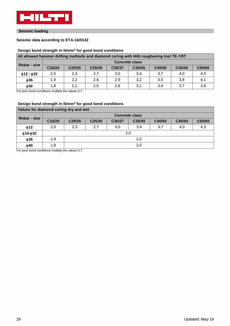
Seismic loading Seismic data according to ETA-16/0142
For poor bond conditions multiply the values 0,7.
For poor bond conditions multiply the values 0,7.
Design bond strength in N/mm2 for good bond conditions
All allowed hammer drilling methods and diamond coring with Hilti roughening tool TE-YRT
Rebar - size
Concrete class
C16/20 C20/25 C25/30 C30/37 C35/45 C40/50 C45/55 C50/60
12 - 32 2,0 2,3 2,7 3,0 3,4 3,7 4,0 4,3
36 1,9 2,2 2,6 2,9 3,2 3,5 3,8 4,1
40 1,8 2,1 2,5 2,8 3,1 3,4 3,7 3,9
Design bond strength in N/mm2 for good bond conditions
Values for diamond coring dry and wet
Rebar - size
Concrete class
C16/20 C20/25 C25/30 C30/37 C35/45 C40/50 C45/55 C50/60
12 2,0 2,3 2,7 3,0 3,4 3,7 4,0 4,3
14-32 2,0
36 1,9 2,0
40 1,8 2,0

Updated: May-19 30
Fire resistance
Temperature reduction factor kfi(θ)
The analytic equation that describe the variation of kfi(θ) with temperature is given by the following function:
If 45ºC ≤ θ ≤ 152ºC: 𝑘𝑓𝑖(𝜃) =ƒ𝑏𝑚(𝜃)
ƒ𝑏𝑚,𝑟𝑞𝑑,𝑑 ≤ 1,0 in ºC
If θ < 45ºC 𝑘𝑓𝑖(𝜃) = 1,0
If θ > 152ºC 𝑘𝑓𝑖(𝜃) = 0,0
With: ƒ𝑏𝑚(𝜃)= 1178,2· θ-1,255 θ in ºC
According to MRF 1526054277 / B
a) Anchoring application
Anchoring application beam-wall connection with a concrete cover of 20 mm
Maximum force in rebar in conjunction with HIT-RE 500 V3 as a function of embedment depth for the fire resistance classes F30 to F240 (yield strength fyk = 500 N/mm² and concrete class C20/25) according EC2
Rebar-size Max. Fs,T linst Fire resistance of bar in [kN]
[kN] [mm] R30 R60 R90 R120 R180 R240
8 16,8
100 3,8 1,3 0,5 0,2 0,0 0,0
140 7,2 4,3 2,3 1,5 0,7 0,2
180 10,7 7,8 5,6 3,9 2,1 1,3
220 14,2 11,2 9,1 7,4 4,6 2,9
250
16,8
13,8 11,7 10,0 7,1 4,8
290
16,8
15,1 13,5 10,6 8,1
310
16,8
15,2 12,3 9,8
330
16,8
14,0 11,6
370 16,8
15,0
390 16,8
inst
31 Updated: May-19
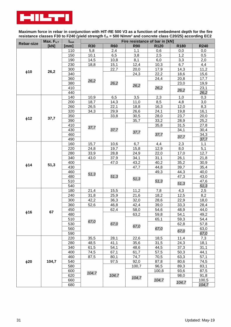
Maximum force in rebar in conjunction with HIT-RE 500 V3 as a function of embedment depth for the fire resistance classes F30 to F240 (yield strength fyk = 500 N/mm² and concrete class C20/25) according EC2
Rebar-size Max. Fs,T linst Fire resistance of bar in [kN]
[kN] [mm] R30 R60 R90 R120 R180 R240
10 26,2
110 5,8 2,4 1,1 0,6 0,0 0,0
150 10,1 6,5 3,8 2,5 1,2 0,5
190 14,5 10,8 8,1 6,0 3,3 2,0
230 18,8 15,1 12,4 10,3 6,7 4,4
300
26,2
22,7 20,0 17,9 14,3 11,2
340
26,2
24,3 22,2 18,6 15,6
360
26,2
24,4 20,8 17,7
380
26,2
23,0 19,9
410 26,2
23,1
440 26,2
12 37,7
140 10,9 6,5 3,5 2,3 1,0 0,3
200 18,7 14,3 11,0 8,5 4,8 3,0
260 26,5 22,1 18,8 16,3 12,0 8,3
320 34,3 29,9 26,6 24,1 19,8 16,1
350
37,7
33,8 30,5 28,0 23,7 20,0
390
37,7
35,7 33,2 28,9 25,2
410
37,7
35,8 31,5 27,8
430
37,7
34,1 30,4
460 37,7
34,3
490 37,7
14 51,3
160 15,7 10,6 6,7 4,4 2,3 1,1
220 24,8 19,7 15,8 12,9 8,0 5,1
280 33,9 28,8 24,9 22,0 17,0 12,7
340 43,0 37,9 34,1 31,1 26,1 21,8
400
51,3
47,0 43,2 40,2 35,2 30,9
430
51,3
47,7 44,8 39,7 35,4
460
51,3
49,3 44,3 40,0
480
51,3
47,3 43,0
510 51,3
47,6
540 51,3
16 67
180 21,4 15,5 11,2 7,8 4,3 2,5
240 31,8 25,9 21,6 18,2 12,5 8,2
300 42,2 36,3 32,0 28,6 22,9 18,0
360 52,6 46,8 42,4 39,0 33,3 28,4
450
67,0
62,4 58,0 54,6 48,9 44,0
480
67,0
63,2 59,8 54,1 49,2
510
67,0
65,1 59,3 54,4
530
67,0
62,8 57,8
560 67,0
63,0
590 67,0
20 104,7
220 35,5 28,1 22,6 18,5 11,4 7,3
280 48,5 41,1 35,6 31,5 24,3 18,1
340 61,5 54,1 48,6 44,5 37,3 31,1
400 74,5 67,1 61,7 57,5 50,3 44,1
460 87,5 80,1 74,7 70,5 63,3 57,1
540
104,7
97,5 92,0 87,8 80,6 74,5
580
104,7
100,7 96,5 89,3 83,1
600
104,7
100,8 93,6 87,5
620
104,7
98,0 91,8
660 104,7
100,5
680 104,7
Updated: May-19 32
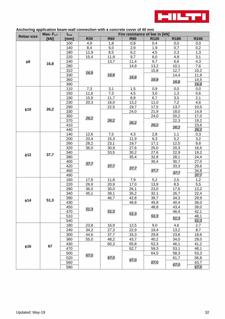
Anchoring application beam-wall connection with a concrete cover of 40 mm
Rebar-size Max. Fs,T linst Fire resistance of bar in [kN]
[kN] [mm] R30 R60 R90 R120 R180 R240
8
16,8
100 4,9 1,8 0,8 0,4 0,0 0,0
140 8,4 5,0 2,9 1,9 0,7 0,2
180 11,9 8,5 6,2 4,5 2,3 1,3
220 15,4 11,9 9,7 8,0 4,9 3,1
240
16,8
13,7 11,4 9,7 6,6 4,3
280
16,8
14,9 13,2 10,1 7,6
310
16,8
15,8 12,7 10,2
330
16,8
14,4 11,9
360 16,8
14,5
390 16,8
10 26,2
110 7,3 3,1 1,5 0,9 0,0 0,0
150 11,6 7,3 4,5 3,0 1,3 0,6
190 15,9 11,7 8,9 6,7 3,5 2,1
230 20,3 16,0 13,2 11,0 7,2 4,6
290
26,2
22,5 19,7 17,5 13,7 10,5
330
26,2
24,0 21,9 18,0 14,9
350
26,2
24,0 20,2 17,0
370
26,2
22,3 19,2
410 26,2
23,6
440 26,2
12 37,7
140 12,6 7,5 4,3 2,8 1,1 0,3
200 20,4 15,3 11,9 9,3 5,2 3,2
260 28,2 23,1 19,7 17,1 12,5 8,8
320 36,0 30,9 27,6 25,0 20,3 16,6
340
37,7
33,5 30,2 27,6 22,9 19,2
380
37,7
35,4 32,8 28,1 24,4
400
37,7
35,4 30,7 27,0
420
37,7
33,3 29,6
460 37,7
34,8
490 37,7
14 51,3
160 17,8 11,8 7,9 5,2 2,5 1,2
220 26,9 20,9 17,0 13,9 8,5 5,5
280 36,0 30,0 26,1 23,0 17,6 13,2
340 45,1 39,1 35,2 32,1 26,7 22,4
390
51,3
46,7 42,8 39,7 34,3 29,9
430
51,3
48,8 45,8 40,4 36,0
450
51,3
48,8 43,4 39,0
470
51,3
46,4 42,1
510 51,3
48,1
540 51,3
16 67
180 23,8 16,9 12,5 9,0 4,6 2,7
240 34,2 27,3 22,9 19,4 13,2 8,7
300 44,6 37,7 33,3 29,8 23,6 18,6
360 55,0 48,2 43,7 40,2 34,0 29,0
430
67,0
60,3 55,8 52,3 46,1 41,2
470
67,0
62,7 59,3 53,1 48,1
500
67,0
64,5 58,3 53,3
520
67,0
61,7 56,8
560 67,0
63,7
580 67,0

33 Updated: May-19
Rebar-size Max. Fs,T linst Fire resistance of bar in [kN]
[kN] [mm] R30 R60 R90 R120 R180 R240
20 104,7
220 38,4 29,8 24,2 19,9 12,2 7,8
300 55,7 47,2 41,6 37,3 29,5 23,3
380 73,1 64,5 58,9 54,6 46,8 40,6
460 90,4 81,9 76,3 71,9 64,2 57,9
530
104,7
97,0 91,4 87,1 79,3 73,1
570
104,7
100,1 95,8 88,0 81,8
600
104,7
102,3 94,5 88,3
620
104,7
98,9 92,6
650 104,7
99,1
680 104,7
25 163,6
280 64,2 53,6 46,6 41,1 31,4 23,7
370 88,6 77,9 70,9 65,5 55,8 48,0
460 113,0 102,3 95,3 89,9 80,2 72,4
550 137,4 126,7 119,7 114,3 104,6 96,8
650
163,6
153,8 146,8 141,4 131,7 123,9
690
163,6
157,7 152,2 142,5 134,7
720
163,6
160,4 150,7 142,9
740
163,6
156,1 148,3
770 163,6
156,4
800 163,6
28 205,3
310 81,1 69,1 61,3 55,2 44,3 35,6
370 99,3 87,3 79,5 73,4 62,5 53,8
430 117,5 105,5 97,7 91,6 80,7 72,0
490 135,7 123,7 115,9 109,8 98,9 90,2
550 153,9 141,9 134,1 128,0 117,2 108,4
610 172,1 160,1 152,3 146,2 135,4 126,6
670 190,3 178,3 170,5 164,4 153,6 144,8
720
205,3
193,5 185,7 179,6 168,7 160,0
760
205,3
197,8 191,8 180,9 172,2
790
205,3
200,9 190,0 181,3
810
205,3
196,1 187,3
850 205,3
199,5
870 205,3
32 268,1
350 106,5 92,8 83,9 76,9 64,5 54,6
410 127,3 113,6 104,7 97,8 85,3 75,4
470 148,1 134,5 125,5 118,6 106,1 96,2
530 168,9 155,3 146,3 139,4 127,0 117,0
590 189,7 176,1 167,1 160,2 147,8 137,8
650 210,6 196,9 187,9 181,0 168,6 158,6
710 231,4 217,7 208,7 201,8 189,4 179,4
820
268,1
255,8 246,9 240,0 227,5 217,6
860
268,1
260,8 253,8 241,4 231,4
890
268,1
264,2 251,8 241,8
910
268,1
258,7 248,8
940 268,1
259,2
970 268,1

Updated: May-19 34
b) Overlap joint application
Max. bond stress, fbd,FIRE , depending on actual clear concrete cover for classifying the fire resistance.
It must be verified that the actual force in the bar during a fire, Fs,T , can be taken up by the bar connection of the
selected length, inst. Note: Cold design for ULS is mandatory.
Fs, T (inst – cf) fbd,FIRE where: (inst – cf) s;
s = lap length
= nominal diameter of bar
inst – cf = selected overlap joint length; this must be at least s,
but may not be assumed to be more than 80
fbd,FIRE = bond stress when exposed to fire
Critical temperature-dependent bond stress, fbd,FIRE, concerning “overlap joint” for Hilti HIT-RE 500 V3 injection adhesive in relation to fire resistance class and required minimum concrete coverage c.
Clear concrete cover c Max. bond stress, c [N/mm²]
[mm] R30 R60 R90 R120 R180 R240
30
40 0,8
50 1,1
60 1,5
70 2,1 0,9
80 2,9 1,2
90 3,5 1,5 0,9
100
1,8 1,1 0,8
110 2,3 1,4 1,0
120 2,8 1,6 1,2
130 3,4 2,0 1,4 0,9
140 3,5 2,3 1,6 1,0
150
2,8 1,9 1,1 0,8
160 3,3 2,2 1,3 0,9
170 3,5 2,5 1,5 1,1
180
2,9 1,7 1,2
190 3,4 1,9 1,4
200 3,5 2,2 1,5
210
2,5 1,7
220 2,8 1,9
230 3,1 2,1
240 3,5 2,3
250
2,6
260 2,9
270 3,2
280 3,5
290

35 Updated: May-19
Materials
Properties of reinforcement
Designation Material
Reinforcing bars (rebars)
Rebar EN 1992-1-1 Bars and de-coiled rods class B or C with fyk and k according to NDP or NCL of EN 1992-1-1 fuk = ftk = k · fyk
Fitness for use Some creep tests have been conducted in accordance with ETAG guideline 001 part 5 and TR 023 in the following conditions: in dry environment at 50 °C during 90 days. These tests show an excellent behaviour of the post-installed connection made with HIT-RE 500 V3: low
displacements with long term stability, failure load after exposure above reference load.
Resistance to chemical substances
Chemicals tested Content
(%) Resistance Chemical tested
Content
(%) Resistance
Toluene 47,5 + Sodium hydroxide 20% 100 -
Iso-octane 30,4 + Triethanolamine 50 -
Heptane 17,1 + Butylamine 50 -
Methanol 3 + Benzyl alcohol 100 -
Butanol 2 + Ethanol 100 -
Toluene 60 + Ethyl acetate 100 -
Xylene 30 + Methyl ethyl ketone (MEK) 100 -
Methylnaphthalene 10 + Trichlorethylene 100 -
Diesel 100 + Lutensit TC KLC 50 3 +
Petrol 100 + Marlophen NP 9,5 2 +
Methanol 100 - Water 95 +
Dichloromethane 100 - Tetrahydrofurane 100 -
Mono-chlorobenzene 100 o Demineralized water 100 +
Ethylacetat 50 - Salt water saturated +
Methylisobutylketone 50 - Salt spray testing - +
Salicylic acid-
methylester
50 + SO2 - +
Acetophenon 50 + Enviroment/wheather - +
Acetic acid 50 - Oil for formwork (forming oil) 100 +
Propionic acid 50 - Concentrate plasticizer - +
Sulfuric acid 100 - Concrete potash solution - +
Nitric acid 100 - Concrete potash solution - +
Hydrochloric acid 36 - Saturated suspension of
borehole cuttings - +
Potassium hydroxide 100 -
+ Resistant - Not resistant o Partially Resistant
Electrical Conductivity
HIT-RE 500 V3 in the hardened state is not conductive electrically. Its electric resistivity is 661012 .m (DIN IEC 93 – 12.93). It is adapted well to realize electrically insulating anchorings (ex: railway applications, subway). Installation temperature range -5°C to +40°C

Updated: May-19 36
Service temperature range Hilti HIT-RE 500 V3 injection mortar may be applied in the temperature ranges given below. An elevated base material temperature may lead to a reduction of the design bond resistance.
Temperature range Base material
temperature
Maximum long term
base material
temperature
Maximum short term
base material
temperature
Temperature range I -40 °C to +80 °C +50 °C +80 °C
Max short term base material temperature Short-term elevated base material temperatures are those that occur over brief intervals, e.g. as result of diurnal cycling. Max long term base material temperature Long-term elevated base material temperatures are roughly constant over significant periods of time.
Working time and curing time 1)
Temperature of the
base material
Working time in which rebar can be inserted and
adjusted tgel
Initial curing time tcure,ini
Curing time before rebar can be fully loaded tcure
5 °C TBM -1 °C 2 h 48 h 168 h
0 °C TBM 4 °C 2 h 24 h 48 h
5 °C TBM 9 °C 2 h 16 h 24 h
10 °C TBM 14 °C 1,5 h 12 h 16 h
15 °C TBM 19 °C 1 h 8 h 16 h
20 °C TBM 24 °C 30 min 4 h 7 h
25 °C TBM 29 °C 20 min 3,5 h 6 h
30 °C TBM 34 °C 15 min 3 h 5 h
35 °C TBM 39 °C 12 min 2 h 4,5 h
TBM = 40 °C 10 min 2 h 4 h 1) The curing time data are valid for dry base material only. In wet base material the curing times must be doubled.
Setting information
Installation equipment
Rebar – size 8 10 12 14 16 18 20 25 28 32 34 36 40
Rotary hammer TE 2 (-A)– TE 40(-A) TE40 – TE80
Other tools
Blow out pump (hef ≤ 10∙d) -
Compressed air guna)
Set of cleaning brushesb), dispenser, piston plug Roughening tools
a) Compressed air gun with extension hose for all drill holes deeper than 250 mm (for ϕ 8 to ϕ 12) or deeper than 20·ϕ (for ϕ > 12 mm)
b) Automatic brushing with round brush for all drill holes deeper than 250 mm (for ϕ 8 to ϕ 12) or deeper than 20·ϕ (for ϕ > 12 mm.
Minimum concrete cover cmin of the post-installed rebar
Drilling method Bar diameter [mm] Minimum concrete cover cmin
[mm]
Without drilling aid With drilling aid
Hammer drilling (HD) and (HDB)
ϕ < 25 30 + 0,06 · lv ≥ 2 · ϕ 30 + 0,02 · lv ≥ 2 · ϕ
ϕ ≥ 25 40 + 0,06 · lv ≥ 2 · ϕ 40 + 0,02 · lv ≥ 2 · ϕ
Compressed air drilling (CA)
ϕ < 25 50 + 0,08 · lv 50 + 0,02 · lv
ϕ ≥ 25 60 + 0,08 · lv ≥ 2 · ϕ 60 + 0,02 · lv ≥ 2 · ϕ
Diamond coring in wet (PCC) dry (DD)
ϕ < 25 Drill stand works like a drilling aid
30 + 0,02 · lv ≥ 2 · ϕ
ϕ ≥ 25 40 + 0,02 · lv ≥ 2 · ϕ
Diamond coring with Roughening too
ϕ < 25 30 + 0,06 · lv ≥ 2 · ϕ 30 + 0,02 · lv ≥ 2 · ϕ
ϕ ≥ 25 40 + 0,06 · lv ≥ 2 · ϕ 40 + 0,02 · lv ≥ 2 · ϕ
37 Updated: May-19
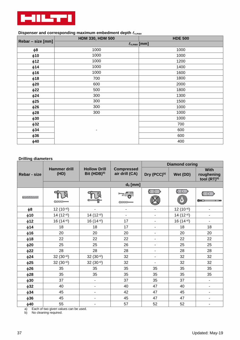
Dispenser and corresponding maximum embedment depth v,max
Rebar – size [mm] HDM 330, HDM 500 HDE 500
v,max [mm]
8 1000 1000
10 1000 1000
12 1000 1200
14 1000 1400
16 1000 1600
18 700 1800
20 600 2000
22 500 1800
24 300 1300
25 300 1500
26 300 1000
28 300 1000
30
-
1000
32 700
34 600
36 600
40 400
Drilling diameters
Rebar - size
Hammer drill (HD)
Hollow Drill Bit (HDB)b)
Compressed air drill (CA)
Diamond coring
Dry (PCC)b) Wet (DD) With
roughening tool (RT)b)
d0 [mm]
8 12 (10 a)) - - - 12 (10 a)) -
10 14 (12 a)) 14 (12 a)) - - 14 (12 a)) -
12 16 (14 a)) 16 (14 a)) 17 - 16 (14 a)) -
14 18 18 17 - 18 18
16 20 20 20 - 20 20
18 22 22 22 - 22 22
20 25 25 26 - 25 25
22 28 28 28 - 28 28
24 32 (30 a)) 32 (30 a)) 32 - 32 32
25 32 (30 a)) 32 (30 a)) 32 - 32 32
26 35 35 35 35 35 35
28 35 35 35 35 35 35
30 37 - 37 35 37 -
32 40 - 40 47 40 -
34 45 - 42 47 45 -
36 45 - 45 47 47 -
40 55 - 57 52 52 - a) Each of two given values can be used. b) No cleaning required.
Updated: May-19 38
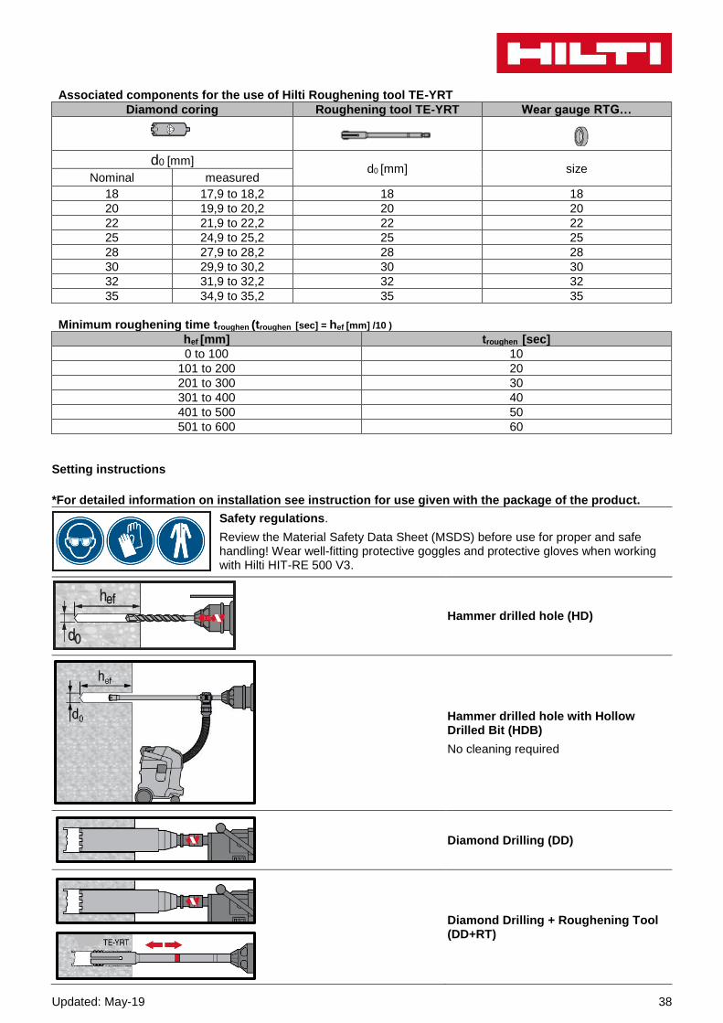
Associated components for the use of Hilti Roughening tool TE-YRT Diamond coring Roughening tool TE-YRT Wear gauge RTG…
d0 [mm] d0 [mm] size
Nominal measured
18 17,9 to 18,2 18 18
20 19,9 to 20,2 20 20
22 21,9 to 22,2 22 22
25 24,9 to 25,2 25 25
28 27,9 to 28,2 28 28
30 29,9 to 30,2 30 30
32 31,9 to 32,2 32 32
35 34,9 to 35,2 35 35
Minimum roughening time troughen (troughen [sec] = hef [mm] /10 )
hef [mm] troughen [sec]
0 to 100 10
101 to 200 20
201 to 300 30
301 to 400 40
401 to 500 50
501 to 600 60
Setting instructions
*For detailed information on installation see instruction for use given with the package of the product.
Safety regulations.
Review the Material Safety Data Sheet (MSDS) before use for proper and safe handling! Wear well-fitting protective goggles and protective gloves when working with Hilti HIT-RE 500 V3.
Hammer drilled hole (HD)
Hammer drilled hole with Hollow Drilled Bit (HDB)
No cleaning required
Diamond Drilling (DD)
Diamond Drilling + Roughening Tool (DD+RT)

39 Updated: May-19
Hammer Drilling:
Manual cleaning (MC) for drill diameters d0 ≤ 20 mm and drill hole depth h0 ≤ 10∙d.
Hammer Drilling:
Compressed air cleaning (CAC) for all drill hole diameters d0 and drill hole depths h0 ≤ 20∙d.
Diamond cored holes:
Compressed air cleaning (CAC) for all drill hole diameters d0 and drill hole depths h0 .
Diamond cored holes with Hilti roughening tool:
Compressed air cleaning (CAC) for all drill hole diameters d0 and drill hole depths h0 .
Injection system preparation.
Injection method for drill hole depth
hef ≤ 250 mm.
Injection method for drill hole depth
hef > 250mm.
Updated: May-19 40
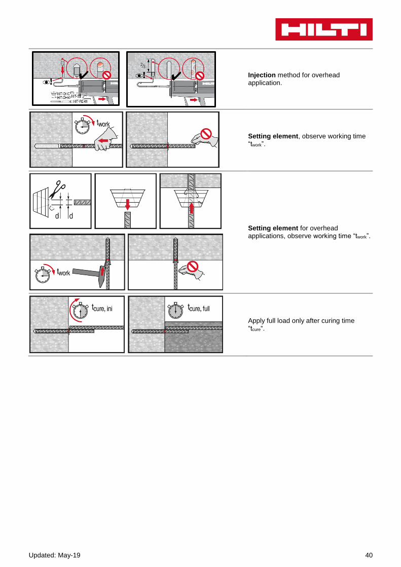
Injection method for overhead application.
Setting element, observe working time “twork”.
Setting element for overhead applications, observe working time “twork”.
Apply full load only after curing time “tcure“.