history of nsa general-purpose electronic digital computers · pdf filensa general-purpose...
TRANSCRIPT

Doc ID: 6586784
.. r
' ~ -· . ·.~
•.
HISTORY OF NSA GENERAL-PURPOSE
ELECTRONIC DIGITAL COMPUTERS
1964
pproved for Release by NSA on 2-09-2004, FOIA Case# 41023
Doc ID: 6586784•
• ' j r I .-,_
HISTORY OF
NSA GENERAL-PURPOSE
ELECTRONIC DIGITAL COMPUTERS
By
Samuel S. Snyder
1964
Department of Defense Washington, D. c. 20301
-FOR OFFICIAL USE ONLY

Doc ID: 6586784I.
r
r
i T--·-----
! I
i
PREFACE
The author has attempted to write this material so that it will be easily understood by those who have had only limited experience with computers. To aid those readers, several terms and concepts have been defined, and Chapter 1 includes a brief discussion of principles of computer operation, programming, data-preparation problems, and automatic programming. Engineering terminology has been held to a minimum, and the history of programmer training, personnel and organizational growth, and-the like has not been treated. To some small extent, the comments on operational utility bring out the very real usefulness of computers for the solution of data-processing problems.
The cutoff date for even'C!:f-related -her·e-·--·was-the end of December 1963.
s.s.s.
ii

Doc ID: 6586784
TABLE OF CONTF.NTS
CHAPTER 1 -- BACKGROUND
·Description
Punched Card Equipment and the Computer Computers in NSA - - - - - - - - - -Computer Principles - - - - - - - - - -Programming Principles Data Preparation - - - - - - - - - -Automatic Programming - - - - - - - - - - - -Special-Purpose Attachments - - - - -Impact of NSA on Commercial Computer Developments
CHAPTER 2 -- AGENCY-SPONSORED COMPUTERS
Page
ATLAS I and ABEL - - - - - - - - - - - - 8 ATLAS II - - - - - - - - - - - - - - - - - - - - 13 ABNER and BAKER - - - - - - - - - - - - - - - 14 NOMAD - - - - - - - - - - - - - - - - .28 SOLO - - - - - - - - - - - - 29 BOGART - - - - - - - - - - - 31 CUB - - - - - - - - - - - .36 UNIVAC 1224A (CRISPI) - - - - - - - - - - - - - - .36 HARVEST - - - - - - - - - - - - - - - - - .39
HARVEST Modes of Operation - - - - - - - - 46 --Ar-i-thme.t-ic Mode -- - - - - - - - - - - - A-6 ___ _
Streaming Mode - - - - - - - - - - 55 Indexing and Setup - - - - - - - - 58 Streaming Instructions - - - - - - 59 Adjustments - - - - - - - - - - 59 Special Memory Features - - - - - - - - 59
TRACTOR - - - - - - - - - - - - - 60 HARVEST Operational System (HOPS) - - - - .61
CHAPTER 3 -- COMMERCIAL COMPUTERS
International Business Machines Corporation - ·6: IBM-701 - - - - - - - - - - - - - - - 65 IBM-7 0 2 - - - - - 6 6 IBM-705 - - - - - ~6 IBM-704 - - - - - - - - - - - 67 IBM-650 - - - - - - - - - - - - - - - 67 IBM-1401 - - - - - - - - - - - - - - - 71 IBM-1410 - - - - - - - - - - - - - - - 71 IBM-7090 - - - - - - - - - - - - - - - 76
iii
oc ID: 6586784
iv
TABLE OF CONTENTS
(CONTINUED)
Description Page
General Precision, Inc. - - - - - - - - - - - - - 76 LGP-30 - - - - - - - - - - - - - - - - - - - - 76
Control Data Corporation - - - - - - 78 CDC-1604 - - - - - - - - - - - - - - - - - - - 78 CDC-160A - - - - - - - - - - - 82
CHAPTER 4 -- REMOTE-OPERATED COMPUTERS
ROGUE (ALWAC IIIE) ROB ROY (BOGART) RYE (UNIVAC 490)
- - - - 85 88
- - - - 89
APPENDIX
Table 1. Chronological Listing - - - - - - - - - 93 11 2. ATLAS I Instruction Code - - - - - - 9 6 11 3. U.S. Electronic Computer Ac ti vi ty II in 1947 - - - - - - - - - - - - - - - - 97 11 4 • ABNER Instruction Code - - - 9 8
References - - - - - - - - - - - - - - - - - - - 99
------ fLLlfSTRATIONS
Figure Description Page
1 Block Diagram of Digital Computer 3 2 Typical Problem Flow Chart - - - - 5 3 ATLAS I Console - - - - - - - - - - - 9 4 ATLAS I Main Frame, with Input Tape
Reader in Foreground,. Console in Back 9 5 ABEL - - - - - - - - - - - - - - - 11 . 6 ATLAS II Main Frame (Partial View) - - - - 15 7 ATLAS II Console - - - - - - - - - - - - - 15 8 ATLAS II Input-Output - - - - - - 16 9 Mercury Delay Line (Diagrammatic) 18
10 ABNER (1) Memory Cabinet - - - - - - - 20 11 ABNER (1) Console Panel - - - - - - - 24 12 ABNER (2) Console - - - - - - - - - - 25 13 ~.(2) Raytheon Tape Drives - - - - 25 14 ABNER (2) Main Frame - - - - - - - - - 26
----- ---·- . vs ii@ ·= £i

oc ID: 6586784
Illustrations (continued)
Figure Description Page
15 BAKER - - - - - - - - - - - - - - - - 26 16 SOLO - - - - - - - - - - - - - - - 32 17 BOGART Console, with IBM 727 Tape Drives - 34 18 BOGART, Serial 2 - - - - - - - - - 35 19 CUB - - - - - - - - - - - - - - - 37 20 Partial View of CRISPI, Showing Paper-Tape
Input, UNIVAC 1224A, and "B" Console - 37 21 HARVEST System Block Diagram - - - - - - - 44 22 HARVEST Operator's Console, Showing IBM
1403 Line Printer, Right Background - - - 47 23 HARVEST Operating Area, General View,
Showing TRACTOR in Left Background - - - 48 24 HARVEST Maintenance and Engineering Con-
soles: Arithmetic and Logic Unit (left) Streaming Unit (right} - - - - - - 49
25 HARVEST -- The 16 Frames of the Central Processing Unit - - - - - - - - - - - - - 50
26 HARVEST Tape Control Units and Tape Drives 51 27 HARVEST -- The 6 Large Memories - - - - - 52 28 HARVEST -- One Unit of the Fast Memory - - 53 29 HARVEST -- TRACTOR Cartridge Handler - - - 54 30 HARVEST Streaming Data Paths - - - - - - - 56 31 IBM-705, Showing SINBAD Control Panel at
Right of 705 Console - - - - - - - 68 32 IBM-705 Core Memory - - - - - - - - - 69 33 IBM-704 - - - - - - - - - - - - - 70 34 IBM-704 Core-Memo-ry-------------- -- - -- - - - 70 35 IBM-650 General View - - - - - - - - - 72 36 IBM-650 Console - - - - - 72 37 IBM-650 Disk Storage - - - - - - - - - 73 38 IBM-650 Inquiry Station - - - - - 74 39 IBM-1401 - - - - - - - - - - - 75 40 IBM-7090 Console - - - 77 41 LGP-30 - - - - - - - - - - - - 79 42 WELCHER - - - - - - - - - 80 43 CDC-1604 - - - - - - - - - 81 44 Control Data 160-A Computer - 83 45 ALWAC IIIE - - - - - - - - 87 46 ROB ROY Outstation - - - - - - 90 47 ROB ROY Control Panel - - - - - - - - 90 48 UNIVAC 490 {RYE) General View - - - - 91
v
oc ID: 6586784
·!!~ . .•. .~
~ · r-'r
Ji? . ~-·· :,T-·
C~PTER 1 BACKGROUND
Most writers on digital computer development tend to start with discussions of the abacus and continue with Charles Babbage's Analytic Engine, the desk calculator, and the big relay calculators of Bell Laboratories and Harvard. Indeed, the development of computing machinery did follow such a path. But the role of computers at NSA can be better appreciated when considered from the viewpoint of application.
Punched Card Equipment and the Computer
The extraordinary versatility and efficiency of electronic computers have made them useful in handling almost every class of data-processing and analytic problem. From this point of view and in this respect, at NSA, punched-card equipment -keypunch, reproducer, sorter, collator, and tabulator -- could be called the forerunners of the electronic computer.
For the 15 years beginning about 1935, NSA's predecessors used punched.-card equipment to attack wider and wider ranges of problems. During this time many special-purpose machines were also built, including some designed a~ attachments to punched-card equipment. The use of punched~card equipments as general-purpose tools continued to grow until, by the end of World War II, 750 machines had been installed.
Punched-card equipment -- keypunch, reproducer, sorter, co-llator, and tabulator -- were the forerunr1er·s--0Ith·e--e1ectronic computer in every respect excepting speed and automatic operation. · This is true because of the use of the punched-card as a unit record, flexibility of plugboard together with switching capabilities in each machine, and versatility ~nherent in successive card passes through different equipments. The following types of data analyses could be done using punched-card equipments:
expanding, reproducing (Reproducer) distributing, sorting (Sorter) merging, selecting (Collator) counting, printing (Tabulator)
The general-purpose computer logically corresponds to punched-card equipment in that a variety of elementary operations (the order code) can be combined in a variety of ways
I

Doc ID: 6586784
(the programl) and applied to unit records (data stored in specific memory locations). The versatility is further increased by treating the program steps (instructions) as data themselves and eliminating the necessity for manual operations between successive logical operations. Finally, the great difference in speed made possible by electronic circuitry in the large computers has virtually elirilinated the punched-card approach as our principal general-purpose tool.
Computers in NSA
With the earliest design work on computers, in 1946, came the realization of the potential usefulness of such machines for Agency purposes. Quite probably this Agency's predecessors were the first to develop sophisticated analytic applications of such machines. This story is detailed later in the·discussions of ATLAS I and ABNER. The use of computers by NSA has increased considerably, ·beginning with one of the first machines in the country, installed in December 1950.
NSA's computer installation probably ranks among the largest in the country. The chronological listing (Table 1, page 93) shows these acquisitions in the order of their installation and includes references to the page in the text where each computer is discussed.
Computer Principles
Most modern electronic digital computers, begin:tiTiicf----·-·- - _____ _ --· . . -.. .
wi-th the ·su:cc-essors to the famous ENIAC, have been composed of four principal units: input-output, storage, arithmetic, and control (fig. 1). Data and instructions, prepared in advance on some lt\achine-readable medium (punched cards, tape, and the like), are fed into the machine system, and the data is operated on automatically, according to the steps specified in the instructions. Such instructions are stored in the same internal storage medium as the problem data but are interpreted by the control unit. An "instruction" normally indicates: (1) the operation to be performed by the arithmetic unit, (2) the location in storage (its address) of one or more operands, and (3) the address of the result of the operation. One of the reasons for the great flexibility of the modern computer is its ability to modify its own instructions or the course of problem solution, depending upon intermediate results. A variation of this capability is the technique of causing the incoming data-stream characters themselves to form addresses for insertion in skeleton instructions later to be executed.
2
• JR! P.'W.l -.. ..... .c.:- ....
L;:_ _r .... ,...i' •• .A • -~~_,__.__
.}, .

Doc ID: 6586784
/
/ /
JI.
··- -· --- -------
INPUT-OUTPUT
---- Data Paths ____ Control Paths
CONTROL
I I ' + '
STORAGE
Figure 1.-Block Diagram of Digital Computer
I I
----- -
ARITHMETIC
3

Doc ID: 6586784r
i I l
l
I
-
L
Programming Principles
Any analytic or data-processing requirement, however complex, can be logically reduced to a succession of elementary operations that follow from binary decision-points (yesor-no choices}, provided knowledge exists of a logical method of attack. A flow chart (fig. 2) for a sample problem shows the use of such dichotomous, or two-choice, logic to break a complex problem into the major steps that will lead to possible solution. In similar fashion, each of such major steps is susceptible to further breakdown into smaller, more detailed, steps, and so on down to the individual elementary machine operations that are the smallest logical unit and that correspond to the individual computer instructions.
Data Preparation
An important and essential aspect of the use of any data processing machines is the initial step -- the preparation of data for input. In connection with the general-purpose use of punched-card equipment, the key-punch has been mentioned as providing means of transforming information into a form that can be read by other machines. The key-punch perforates cards in specific positions to represent data under study. Punched paper tape is also used as machine input and is usually punched in 5- or 7-level codes. Recently the use of magnetic tape has increased, although it must usually be prepared from punched- cards or--ta-pe-.---~ points should be emphasized:
1. Our method for going from hard copy to machine-readable mediums has not improved -- a small army of key-punchers and paper-tape punchers is still employed.
2. The existence of several media, here and in the field, requires the use of large quantities of equipment and time just to convert from one medium to another (frequently several times within one job)-. Many machines, including several general-purpose computers, have been built for the sole purpose of data conversion and rearrangement.
Automatic Programming
In the preceding.brief description of the principal parts of the typical computer arid of organizing a problem for computer attack, the necessity for a breakdown into elementary operations was pointed out. Most of these elementary operations are more detailed -- require much finer attention -- than people are accustomed to. When a workable program
4
·=· ~-·---- I ·.:Z'i o.up A

Doc ID: 6586784
START---- READ IN (NEXT) TEXT
EXAMINE (IDENTIFY) FIRST (NEXT) CHARACTER
ADD "1" TO MEMORY CELL FOR THAT CHARACTER
ADD "1" TO MEMORY CELL FOR TOTAL CHARACTERS
SET UP AND EXECUTE PRINT ROUTINE- -
rCLEAR CHARACTER COUNT CELLS AND TOTAL CELL
STOP
FIGURE 2. TYPICAL PROBLEM. FLOW CHART --
YES
YES
.FREQUENCY DISTRIBUTION OF ALPHABETIC TEXT
·1
NO
NO
5

Doc ID: 6586784
~·
(or routine or subroutine, as smaller subdivisions are called) is completed, it is natural to try to avoid the necessity of repeating the whole. operation the next time this particular function is req~ired. As a result, routines of standard functions are commonly stored in "libraries," and special programs, called "compilers," perform the function of combining several such routines and adjusting addresses for varying conditions. To facilitate the writing of machine-language instructions, the instruction codes of .many computers use mnemonics that must later be converted into the individual computer words. Programs for performing this conversion automatically are called "assemblers." Higher forms of languages have been developed that use a combination of rigorous English and mathematical notation to express functions and parameters of problems and thus release the analyst/ programmer from becoming a full-time machine specialist. Programs for transforming these higher languages are called "translators:" they generate actual computer programs ready to execute a problem solution. Special programs for regulating overall computer operations, keeping records, monitoring various types of simultaneous operations, and for many other purposes are called "supervisors" or "executive" routines. In the past, programmers in NSA have been less inclined to use these techniques than computer users in other fields, primarily because commercially developed systems have been unsuited to the specialized nature of Agency operations. More recently, however, such techniques have become the rule, and the great ALPHA language-development effort required for HAR-
·-vEST-;-- for example, will certainly have -a:·- far-reaclifi1cj- -effect on future large systems.
Special-Purpose Attachments
In large-scale equipment planning, more and more use is being made of the combination of several kinds of equipment into single ·operating complexes. Actually, this procedure parallels what was done many years ago when attachments were built to function with the IBM Tabulator. In 1954 the FARMER proposal first suggested the idea of special attachments to a computer, and the design of HARVEST made specific provision for the attachment of external function devices. The currently popular application of this principle is the designing of highly efficient counting, comparing, or other processing devices for attachment to a general-purpose computer for use in sophisticated attacks on complicated problems to achieve greater efficiency than would be possible using the computer alone.
Impact of NSA on Commercial Computer Developments
In addition to contracts for computer purchase or lease and the development of engineering techniques, the primary
6
D: 6586 8
influence of NSA on industry has been felt in those instances where technical leadership or management foresight has influenced or led directly to industrial computer pioneering. A few examples follow.
First, the sponsorship of the ATLAS I by NSA's Navy predecessor led directly to placing Engineering Research Associates on a firm footing as one of the country's pioneering computer firms. ERA's commercial 1101 and 1103 computers were almost identical to ATLAS I and ATLAS II respectively. With the merger of ERA and the Eckert-Mauchly Corporation into the Remington-Rand-1JNIVAC organization, the 1101 and 1103 became a part of the UNIVAC line. Through the National Bureau of Standards, NSA's Army predecessor contracted for the construction of a 111ercury delay line memory for ABNER. The Technitrol Corporation not only built memories for ABNER and the National Bureau of Standards' SEAC, but later constructed the second ABNER and received a series of contracts for equip-ment using similar components. Technitrol went on to market a varied line of special and general-use equipment, much of it based on this experience. Another example is NSA's NOMAD contract with Raytheon Corporation. The NOMAD design was the direct forerunner of the Datama.tic ~1000, which was transformed into one of the early 10.achines in the Honeywell line. The realization, in 1955, that the transistor had a brJgll.t future .... -··-- - -as an el.ectronic · component, led to this Agency's ·sponsorship of the construction by Philco Corporation of NSA's first practical, transistorized computer, SOLO. Marketed conuner-cially as the Transac S-1000, it became the world's first commercial transistorized computer. Beginning with the EDPM Type 701, the Agency-IBM experience is very impressive. Probably very few realize that IBM based much of its early computer philosophy upon NSA's experience with large data-processing problems. Certain features of the 704, representing improve-ments on the 701, resulted from sugges~ions by NSA personnel; similarly, the 702 was improved to become the 705. The PLAN-TATION (later RANCHO) study contract for HARVEST design, as well as NSA support for memory and magnetic tape researches, not only influenced IBM's 7030 (STRETCH) but also resulted in solving a number of fundamental logic and processing problems never before confronted in the computer field. Finally, the LIGHTNING researches into ultra-high-speed computer circuits and components -- work done under contract by IBM, RemingtonRand-UNIVAC, RCA, and others -- have undoubtedly had the great-est influence in the development of new computers and other digital equipment with basic operation times measured in nanoseconds (billionths of a second) .
7
jpfij ~4·.*SQ@:#'.:-*MI.-~··.e .. gg; ·-"¥:..50.•·::'il~• 19w5 ... rs1 l'Mi· ·t:& - ... ~ .... ·=:mm:
Doc ID: 6586784
CHAPTER 2 AGENCY-SPONSORED COMPUTERS
In addition to operating an extensive computer installation, NSA has been a prime sponsor of computer developments. Of the nine electronic computer projects discussed in the following sections, two, ABNER and CUB, were designed and built by NSA (or predecessor) personnel. The rest were built under contract, following logical designs conceived or inspired by NSA personnel.
A~LAS I and ABEL
In the summer of 1946, Moore School of Electrical Engineering, University of Pennsylvania, sponsored a series of lectures on electronic computers. Among those who attended was LCDR James T. Pendergrass, a young mathematician at Navy's Communications Supplementary Activities, Washington (CSAW). As a result of hearing the computer proposals described at that time, LCDR Pendergrass prepared a report in which he proposed that the Navy acquire such a machine. His report included a general description of the proposed machine's logic, its code of instructions, and coded examples of typical problem solutions. The particular design advocated was of the· class known as one-address logic, and was based on the I.A.S. Computer then being developed at the Institute for Advanced Study, Princeton, New Jersey. CSAW went ahead with plans for construction of ATLAS I, and CSAW personnel perfected most of the basic algorithms, or .. a.eta-irea--m.ach-ine logic for executing each instruction. The contractor, Engineering Research Associates of St. Paul, Minnesota, used MIT's WHIRLWIND I logical design to a great extent. ATLAS I was delivered on 8 December 1950 and was running before Christmas. It employed parallel circuitry, contained approximately 2700 tubes, and cost about $950,000. Figures 3 and 4 show views of this machine.
Although the original proposal had specified that !he ATLAS high-speed internal memory was to.utilize Selectron tubes, a decision was made to substitute a 16,384-word magnetic drum of a type similar to one already placed in operation by E.R.A. in other special-purpose equipment built for the Navy. Also, whereas I..CDR Pendergrass's proposal described a machine with 36-bit2 words (each word containing two one-address instructions), the ATLAS I design was finally based upon 24-bit
1 Selectron was the specially-designed electrostatic storage tube under development by Jan Rajchman at RCA's Princeton Laboratories. The development never achieved sufficient reliability for use as a practical computer memory.
r 2 11 bit" -- binary digit ' '
8
:; ) ,.,
Doc ID: 6586784
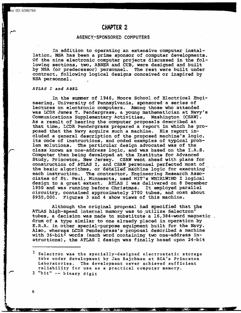
Figure 3 -ATLAS I Console
Figure 4-ATLAS I Main Frame, with Input Tape Reader in Foreground, Console in Background 9

oc ID: 6586784
words {each with one single-address instruction). The drum memory was equipped with a flexible feature called "interlace," that permitted variations in address layout to be made for each program, using a plugboard setup. In effect, "lines" around the drum were renumbered by transposing certain bits of the address selection register in order to allow longer or shorter intervals between successive effective addresses, according to the particular needs of the program. Careful programming in conjunction with careful planning of the interlace plugging made it possible to attain extremely high speeds for given programs, compared to running time of programs written without attention to interlace. Thus, ac-
. cess timel could be reduced to 32 microseconds under the best conditions, compared with an average of 8,500 microseconds or a maximum of 17,000 microseconds. In May 1951, a modification, the "skip" feature, was introduced that added flexibility to programming by allowing the program address counter to advance by intervals greater than one {9, 17, 33, or 65). In effect, the operation of the interlace feature was made partly automatic. In June 1951, the installation of a "dial interlace" feature made selection of the interlace plugging simpler and eliminated the necessity of actually changing plugboards. Other features of ATLAS I's original design included logical multiply instruction, vector addition, several forms of ordinary arithmetic instructions, conditional jump instructions, and an elementary input-output procedure using punched paper tape. In 1952, an interesting new feature, the random jump instruction, was added. Employing a separate electronic attachment that supplied random bits of zero or one, this instruction made possible the generation of streams of random charac.:ters. The photoelectric tape-reading equipment-deli-- · vered with ATLAS I was found to be. quite slow (140 characters per second) compared with ATLAS I internal speeds; nor was it under program control. It was replaced by the newly developed Ferranti photoelectric tape reader that had a speed of 300 character$ ·per second. Table 2 contains the ATLAS I instruc-:tion reper.toire.
Shortly after the completion of the ATLAS I design in 1949, a decision was made to construct a relay analog of the equipment, to assist in training programmers and to "debug" its programs (at least logically) before it was delivered. ABEL (fig. 5) was designed and constructed by CSAW personnel in about four months. Logically it was identical to ATLAS I, but its memory drum capacity was 2,047 words instead of 16,384, and its relay circuitry made it several hundred times slower.
1 access time -- time required to locate and read a word from memory into the arithmetic unit or vice-versa.
10

I
I
• I 5 F1gu~e -- ABEL
,. ;~ !
' •
Doc ID: 6586784
12
After an initial period of perfecting operational and maintenance techniques, ABEL proved to be quite reliable. It was used not only for programmer training but also for generating various statistical tables. Principally because of the great difference in capacity of the memories of ATLAS I and ABEL, the latter could not be effectively used to debug large-scale ATLAS programs. After ATLAS I began operating at CSAW, ABEL was dismantled and transferred, through the Office of Naval Research, to the Navy Logistics Project at the George Washington University where it went back into service. After operation on the Navy Logistics Project for a time, it was presented to the George Washington University School of Engineering. Finally, in 1963, GWU presented ABEL to the Albert Einstein High School in Silver Spring, Maryland. Here upon advice of Agency representatives, it was dismantled for-the last time.
Several months before the delivery of ATLAS I, an order was placed with ERA for the construction of another almost identical machine; it was delivered in May 1953. In 1956, both machines were modified by the addition of high-speed corel storage in the amount of 4,096 words. This addition modernized the machines and eased the programmers' burden; for before the addition of the high-speed magnetic-core memory, the extra effort required of programmers in putting instructions and constants in those locations in-the memory best adapted to maximmn use of the interlace feature was often excessive. In 1957, both ATLAS I's were moved to Fort Meade, and in November 1959 both machines were taken out of operation. ATLAS I, Serial 1, was salvaged, and the components used for other purposes;- -in--March 1960-; -·se-r-.ra.-i:- -2 was shipped to the Anti-Submarine Research Center, SACLANT, NATO Forces, at La Spezia, Italy.
From a maintenance point of view, both machines performed extremely well. Although periods of down time for modifications and additions were necessary, the machines were usually operational above 90 percent in a reporting period. Many useful programs were written for ATLAS I, particularly for statistical and mathematical problems. Although the instructions were well-balanced for statistical and analytic uses, and the machines were designed and built for reliable operation, ATLAS I could not be used for problems demanding the handling of large volumes of data because of the lack of a magnetic-tape facility.
1 core -- also, rings or toroids, of magnetic ferrite material, strung at the junctions of intercrossing wires. Each core represents one bit of storage capacity. Thus, a 1,024-word memory of 24-bit words would take the form of a stack of 24 matrices, _each matrix being a square array of cores, 32 cores to a side.

oc ID: 6586784
A'l'LAS II
Seyeral months before ATLAS I was delivered, a new task was established that provided for the design of a successor. ATLAS II and ATLAS I differed in the following respects:
1. Storage -- Whereas ATLAS I had only drum storage, ATLAS II had, in addition, high-speed electrostatic storage for 1,024 words.
2. Word Size -- The word size on ATLAS II was 36 bits. ATLAS I word size was only 24 bits.
3. Instruction Logic -- ATLAS II used two-address instruction logic; ATLAS I, one-address.
4. Order Code -- Instruction sophistication was increased on ATLAS II.
5. Input-output -- ATLAS II trolled input-output instructions. ability was a serious drawback for
had program-con-A lack of this cap
ATLAS I.
Two-address instruction logic was unique among computer projects. In some instructions, the two addresses .specified the locations of two operands; in other instructions, one of the addresses was an operand and the other a destination location. Among the more sophisticated new instructions were the repeat instruction (see ABNER, page l.4), s.everal modular-arithmetic instructions, a scale factor instruction, and an index jump instruction.
ATLAS II was installed in October 1953. A second machine was also constructed,_ and it was-delivered in December 1954. The second ATLAS II differed from the first only in that it had a high-speed ferrite-core memory rather than an electrostatic tube memory. Originally the plan was to equip ATLAS II with Raytheon magnetic-tape drives using a data representation of one character per frame. However, a change was made to a conservative scheme for data representation involving two positions per information bit, resulting in three tape frames per character. Subsequently, this latter representation was felt to be too inefficient for most large problems. With the objective of achieving tape interchangeability and speeding up magnetic-tape operations, a red·esign effort was undertaken. -However, this modification never reached operational effectiveness.
Even though somewhat handicapped by lack of an effective maqnetic-tape system, both ATLAS II 1 s contributed considerably to the solution of many problems. Reliability was high for both machines, but Serial 1 required somewhat more. maintenance attention than Serial 2 because of the electrostatic tube storage. ATLAS I and ATLAS II were forerunners of the first two in a commercial line of Remington-Rand computers, the UNIVAC 1101 and 1103 respectively. Also, ATLAS II was the logical
13
Doc ID: 6586784
model for the first transistorized computer, SOLO {described on page 29}. ATLAS II, Serial 1, was taken out of operation in February 1960 and donated to the University of Texas; Serial 2 was turned over to the Second Army for disposal in May 1962. Figs. 6,· 7, and 8 show three views of ATLAS II.
ABNER and BAKER
In De~ember 1946, the first Pendergrass Report (see ATLAS I, page S} was received at the Army Security Agency, one of NSA's predecessor agencies. The potential value of electronic computers in ASA applications was recognized immediately, and plans were ma.de to consider the acquisition, by ASA, of a machine similar to Navy's proposed ATLAS. At that time, 1947, there ·were four main centers of electronic computer activity (see Table 3, page 97). During 1948, ASA analysts made visits to these installations, attended lectures at the Bureau of Standards' Digital Computer Laboratory, and performed progrannning experiments using ATLAS, UNIVAC, EDVAC, and RAYDAC order codes. The result of these investigations was a report favoring a design using four-address logic (RAYDAC or EDVAC) over the one-address logic (ATLAS or UNIVAC) .
Four-address logic was favored for the following reasons:
1. Time estimates for executing representative operations showed higher speeds. ___ ·--- -
_ ··- _ . 2. A- philosophic convfi:tion that the bulk of computer operations in ASA applications would be characterized by relatively simple operations on many data items rather than more complex operations upon data retained in the accumulator.
In addition, UNIVAC was rejected for Agency use because it used decimal arithmetic internally and could only manipulate data as alphanumeric characters. Because of the many examples of Agency processes using binary notation, .a binary machine was felt to be a definite requirement.
Based on the foregoing report recommendation, attempts were made to get estimates and commitments for building such a machine. The Raytheon Corporation was already committed to complete a first machine for Navy's Bureau of Aeronautics, and would not promise delivery of a second machine in less than three years. Moore School had undertaken to build EDVAC for Army Ordnance and could not consider offers for a possible second machine. In May 1948, Reeves Instrument Corporation announced that it was entering the digital computer field with REEVAC, a proposed machine based on EDVAC design. The basic EDVAC logic provided.for 45-bit words and a maximum of 16 four-·
14
~ ·, ·:
t
- ----------~~~-----------......... -~-~
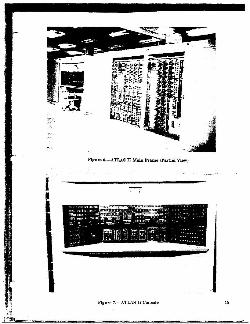
Figure 6.-ATLAS II Main Frame {Partial View)
--·.
Figure 7 .-ATLAS II Console 15
>Jl£*1£AI• 1.-·:.-..- _ 44

Doc ID: 6586784
Figure 8.-ATLAS II Input-Output
16
Doc ID: 6586784
,,._
___ ;-
address instructions. Its 1024-word memory was to be composed of mercury delay lines, with minimum access time being 48 microseconds and actual access varying between 48 and 384 microseconds.
Dr. Samuel Lubkin, formerly at Moore School, headed the effort at Reeves. His proposed design contained several improvements upon the design of the EDVAC, and his price and promised date of delivery were attractive. But just as a contract with the Reeves Corporation was taking form, the company abandoned its plans to produce digital computers and released Dr. Lubkin to the staff of the National Bureau of Standards. Soon after, in August 1948, the Army Security Agency ~~4 the NBS concl~ded an agreement which provided that the Bu~eau-would produce a design for a computer that ASA engineers would build. NBS simultaneously would be designing and building a similar computer for themselves -- one of more modest capabilities. Also, NBS was to place the order for the mercury delay line memories for both machines. Shortly thereafter, several meetings were held to settle on the functional design of the ASA machine, and, to orient ASA engineers in their early design efforts, NBS engineers gave a series of lectures on digital computer logic. The proposed ASA machine was called ABNER.
ABNER's mercury delay line memory was of particular interest. The acoustic delay line was developed around 1946 at the Moore School by Eckert, Sheppard, and Sharpless during planning for EDVAC. A succession of pulses (signal or no-signal) travels through an acoustic medium, say mercury, from one end to the other of a "delay line ... - --FTgure -9---s:hows a diagrammatic view of a mercury delay line. At the input end of the line is a crystal that converts an electrical pulse to a mechanical wave which travels through the mercury to the other end, where another crystal reconverts it to an electrical signal. The series of electrical signals is recirculated back to input, after pass·ing through detector, amplifier, and driver circuits to restore the shape and strength of the pulses. Also, in the part of the cycle external to the delay line are input and output circuits and "clock" pulses for synchronization. In mercury, the pulses travel at the speed of sound, which is much slower than the speed of electrical signals, and thus the delay in going from one end of the line to the other constitutes a form of storage.
In ABNER, the mercury tank was a glass tube about two feet long; the delay time was 384 microseconds, or eight words of 48 bitsl at one-megacycle-per-second rate. Thus the 1,024
I The actual computer word length was 45 bits, allowing a 3-microsecond interval between words.
Doc ID: 6586784
r
r WORD CYCLE POSITIONS ~
-------~ 7:6:5:4:3:2:1 :0
CRYSTAL..J'
DRIVER DETECTOR r
CLOCK *""----~ lE'--t AMPLIFIER
INPUT OUTPUT
FIGURE 9. MERCURY DELAY LINE (DIAGRAMMATIC}
r
18

c ID: 6586784
words were contained in two cabinets holding 64 mercury delay lines each. Figure 10 shows one side of one such cabinet, containing 32 tubes of mercury. (In the figure the actual glass tubes are not visible, being inside the metal cases shown in the upper part of the picture.)
Because of the great variation between minimum access time and the maximum, efforts were made to minimize such delays. Mention has been made above of the improvements possible in ATLAS using ingenuity together with the interlace feature, when special care was taken in placement of words on the drum (page 10). In the case of ABNER, the savings by careful programming was not as great, but worth the effort. Referring to the diagram of Figure 9, a word at cycle position 0 would be immediately available for readout (access time: 48 microseconds), while a word at cycle position 7 would take 8 x 48, or 384 microseconds to be read (or written into). Therefore, instruction words and operands would be carefully placed at memory locations that would be immediately available, if possible, bearing in mind cycle positions (the actual memory address modulo 8) and the known execution times of instructions.
For the next six or eight months, ASA engineers, working closely with several programmers, moved at full speed to perfect the engineering logic of the original set of instructions and devised several additional refinements. Also, primarily to acquire experience, they designed and built an input decimal-_to-binary conversion device. About this time (July 1949-}---it-- - -became apparent to ASA that NBS would not be able to complete the design of ABNER in a reasonable time, principally because of pressure to expedite completion of their own machine, SEAC. So the decision was made to go ahead and build ABNER without waiting for NBS. ASA engineers estimated that they could build the machine in two years.
Meanwhile, the programmers, who had made programming experiments using the several available computer designs, became convinced that Agency operations justified flexibilities in data manipulation not available in these designs or in ABNER" as it was conceived at the time. They began work on a set of special computer instructions to be considered for inclusion in a future improved computer. Three principal classes of operations required special attention: character transformations, data-stream manipulations, and paired stream comparisons. These three lines of attention became interrelated and produced a combined solution that is quite interesting and historically significant. This result was possible because of the intimate working relationship between the programmers and engineers.
19
oc ID: 6586784
r
20
..
$ ••••
• < ,,. I:> 1,$
.(')
mii!!~-- .. •.. @ .@ 41· • @ * .$ • @ ., . • . .., .8 -~ @
-~ -~ ,f!l; • ,, .......... ...-; !'!J---..,.
-~ ~ * • "'t m;-.-: ,$ $ ~
#, ~"" • ., =~t::·: .
; m--..- .$ ~ J/J ...
,.._.:. .... ·- .fit ij ~ J .., [z;+;*1 • • l/J ·-:°) .. i}J • '° ·'1 • Ill -3 $ • .. • a • ti) • 0 • • • 0 • @ • 0 "' • • • t:> • .. • i:> .., • •• •• .. • .... ••• ••• ••• .... ••• ••• , . •-••:: •••• .. ;
ii-Figure 10 -- ABNER Serial l Memory Cabinet
I • ' ~ . ' ~ ~.;;;; """""""""'' .
~ .
r

Doc ID: 6586784
r
. .. ~·;-: ; :~<~~-~;
These new features were incorporated in the lllachine under construction rather than waiting for a successor computer. The following describes briefly how the three requirements were implemented:
1.. Character transformations were treated in the computer as modular addition; that is, the corresponding alphanumeric characters of two words are summed, modulo n, where the value of n varies from 2 to 32. For situations dealing with character sets containing more than 32 characters, two addltional instructions were devised: one that dealt with two streams of 10-bit characters (four in each word) , and another in which the pairs of characters to be acted upon were within the same word .
2. Data stream manipulations originated as a requirement to transfer .groups of words among different portions of internal memory. The first version was thus a block ·transfer of a fixed number of words and was based upon a modification of the Shiftand-Extract instruction so as to repeat the instruction a fixed number of times. The capability of executing such an instruction any number of times came about with the development of the Halt feature. This feature originally was visualized as a means of automatically monitoring computer instruction executions so as to signal the completion of a specific routine. Using the Halt instruction to signal the completion of the final execution of a .rep.eating instruction and extending the repetition feature to apply to most ABNER instructions made these two features -- Halt and Repetition -- completely general and yielded a flexible basis for manipulating streams of data.
3. Paired stream comparison was specified by the programmers as deserving special consideration because of the relative inefficiency of standard computer techniques for performing character-by-character comparison operations. The engineers outdid themselves in satisfying this particular requirement, and the resulting instruction was undoubtedly the most sophisticated ever proposed for a general-purpose computer. Nicknamed "Swish" to depict its action, this instruction accomplished the logical equivalent of a comple.te, high-speed comparator. In effect, it (a) passed two streams of five-bit characters from memory through an analytic unit, (b) compared groups of characters (group size between 1 and 63 characters) for coincidence, (c) counted the number of group coincidences, (d) stored the coincidence count in a memory location specified
21
•

c ID: 6586784
in the same instruction, and (.e) restored one of the streams to 111emory at a specified offset from its original place. in 111emory (offset between zero and eight characters). one significant result of experience with ABNER and the Swish instruction has been .its influence on the design of the Streaming units of HARVEST.
When planning ABNER 1 s input-output features, the design-ers. placed great emphasis on achieving flexibility, sometimes at the expense of speed. The result was an input-output capability more complete and varied than that of any computer commercially available at the time. This included:
l. Up to six magnetic tape drives -- These could be operated for reading or writing in both directions, with words read into or out of 111~.mory in ascending or decending order or not in consecutive order at all. Block size was eight words. Tapes were operable either under computer control or off-line for conversion from or to other media.
2. Punched paper-tape reader and punch -- A CXCOl electric typewriter with a tape reader and punch was first used; later the tape reader was replaced by a Ferranti photoelectric reader with a much greater speed (300 characters per second).
3. Punched-card reader and punch -- An IBM collator for reading punched cards and a modified card punch were operable either under computer contrQl .. or,..o£f~line .using the converting unit. . .....
4. Converting unit -- This unit was designed to accomplish data conversion between almost any two media, including punched paper tape, punched cards, ·magnetic tape, and ABNER storage. It included a plugboard for performing simple character-for-character substitution upon input or output. Its principal utility in practice was as an off-line converter between ma·gnetic tape .and other media.
5. Input/output typewriter -- Direction of insertion of characters into memory words could be chosen, and · substitution plugging on output characters was available.
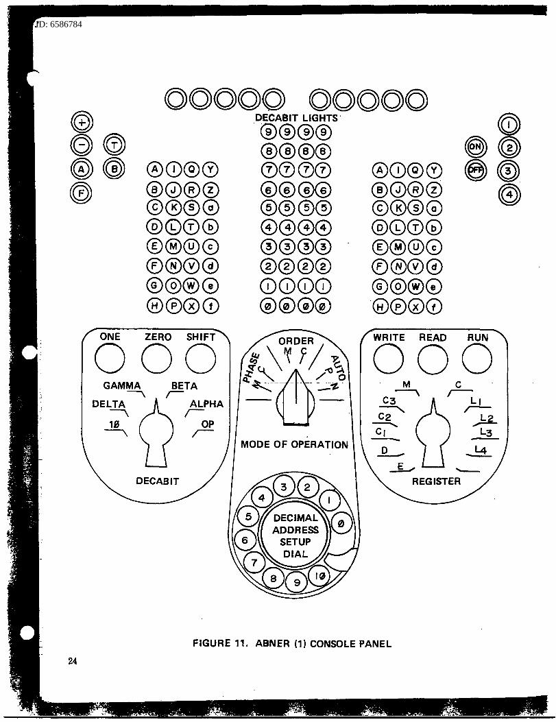
6. console -- Although physically very small (12xl4x10 inches), the console provided great flexibility for manually conununicating with the computer and its various
1 A Navy-sponsored development, manufactured by Commercial Controls Corporation
22

ID: 6586784
registers. Also, a novel feature was its built-in binary-to-decimal and decimal-to-binary conversion equipment for dealing with111emory addresses in ei!;her aeci-mal or binary· form. An array of lights indicated the statug of ltlachine operations ana the causes of 111achine stops. Figure 11 is a drawing of the console controls, only slightly smaller than actual size.
Because the Agency had no prior experience in digital computer design and construction -- indeed, no computers of this magnitude and speed range had yet been completed by anyone -- ASA engineers faced a number of difficult problems. The mercury delay line memory was obtained from the Technitrol Company, and magnetic tape drives were purchased from the Raytheon Manufacturing Company. All other components were ordered from vendors or fabricated in the Agency. For example, one extremely critical item, electric delay lines, had to be designed and fabricated by ASA engineers and technicians. The power supplies, console, and input-output facilities were also troublesome items, primarily because initially they had less reliability than most parts of the computer.
By September 1951, ABNER was completed, and the checking out of individual features got under way. This turned out to be a very complex process, partly because of inadequate instrumentation and also because of the tremendous number of variations and instruction combinations possible. In April 1952, the last analytic instruction was checked out. The complete list of·---ABNER- instructions is reproduced-·in-- Table 4. - -- --
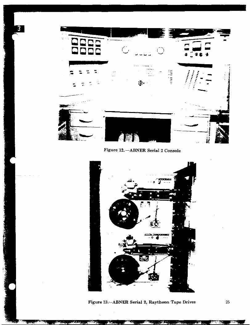
In April 1955, a second ABNER was delivered, constructed under contract by Technitrol Engineering Corporation. Logically it was a copy of ABNER, Serial 1, but it used quartz instead of mercury in the memory's delay lines. An additional innovation was the inclusion of 128 words of rapid access, or "scat," memory, as well as 1024 additional words of main memory. Its engineering and layout were considerably better, and the design of its console was entirely different. A latemodel Remington-Rand line printer was installed later. Much debugging was necessary before the system became reliable, ·so it had not given much operational service when, in 1958, it was moved to Fort Meade. In January 1960 ABNER, Serial 2 was retired from active service. (ABNER, Serial 1, was dismantled a.n.d disposed of when the move to Fort Meade took place.) Fiqures 12, 13, and 14 show three views of the second ABNER.
Compared with ATLAS I, neither model of ABNER had high operational reliability, although they had a number of periods of good "up-time." The use of dynamic serial circuitry in ABNER and a large concentration of complex analytic instruc-
23
ID: 6586784
24
00000 00000
®0®0 ®0®© ©®®0 @©©@ ®®®© ®®®@ ©@®(!) @®00
ONE ZERO SHIFT
000 BETA r-
DECABIT
ALPHA r-
OP ~
DECABIT LIGHTS·
"®®®® ®®®® ©©00 ©©©© ©©©© ©00© @®@® ®®®® ©CD©<D @©@@
MODE OF OPERATION
®CD®© ®0®® ©®©0 @©0@ ®®®0 ®®®© ©®®0 ·@000 WRITE READ RUN
000
FIGURE 11. ABNER (1) CONSOLE PANEL
ID: 6586 8
-·-... 0
.,. . ..
----------··
"" .. ..
Figul"e 12. -ABNER Serial 2 Console
. . . . . . . . . . . . : : tt .. . ~ :
"'.. ...· _;· • cl. . --.. --·
.. ,..,, ___ _ , ,..,,. ______ ____.
' ----- :1 ___ _J,
; . u
Figure 13.=--ABNER Serial 2, Raytheon Tape Drives
.I
25

86784
• r•
j
t.· I• -
t• r·
-~ 1 ..
~·
26
--.......... . _,. ,.,,,,~ . ,. ·-~ ... .. . .. -.. -.;, - ..... , .,,. - ... .. .....
..... -e
........ . . ..
• 4- '~ .... . ..fj
" • °'\" ' ... .. lif~
•• " «. . . ... ... . .... ~ •• 'f."
•' ........ ..... _ j ....
·-·· ... ..... ... _
·-· ...• ' .... -.. ... .,..
Figure 14.-ABNER Serial 2 Main Frame
Figure 15.-BAKER
..... ~~~.~
.. ~·
=·-.,..,:.-!......., -·--.

tions combined to make this .machine extremely difficult to maintain. For example, the" control of temperature of the quartz delay lines in the-memory was always extremely critical, and the ·instruments used forineasurement and regulation were inadequate. Also, the input-output equipment (IBM collator, Remington-Rand printer, electric typewriter, and Raytheon magnetic tape drives) were often out of operation; and computation was ineffective or erroneous when inputoutput errors arose.
However, ABNER design and construction laid the foundation for many important later developments. ABNER was among the first computers in the country to operate successfully magnetic tapes simultaneously with internal computation. Its analytic instructions and other unique features made it possible to perform many specialized Agency data manipulations more efficiently than certain other computers having inherently higher speed circuitry. For the same reasons it was quite popular with programmers. Its "Swish" instruction was a model for several special-purpose machines, and was a forerunner of the HARVEST Streaming units. Many programs made good use of the magnetic-tape capabilities, as well as the analytic instructions.
ABNER, Serial 1, cost approximately $600,000. It contained 1,500 tubes and 25,000 diodes. ABNER, Serial 2 cost about $750 I QQQ.., __
In the fall of 1950, a proposal was made to build a slow-speed analog of ABNER, based on experience in building ABEL, the analog of ATLAS I. Although there was some opposition to this proposal because of ABNER's complexity, the group of engineers who had built ABEL was assigned the task. The new analog was called BAKER and was built using electric relays and a magnetic drum memory.
Although ABNER was designed to use serial circuitry entirely -- in fact, many of its unique analytic features were possible because of that -- BAKER engineers went ahead with the logical design and construction of BAKER using parallel circuitry, and succeeded in simulating the complete ABNER order code. The job took about two years: and, in September 1952, BARER was tested. It was equipped with a slow-speed punched tape reader for input, and an electric typewriter and tape punch for output. Eventually all the logic was checked out, but the machine never operated reliably enough to be of much p~actical assistance in ei~er training programmers or debugging ABNER programs. As a demonstration of a difficult engineering design job, the completion of BAKER was a remarkable achievement. The use of parallel

ID: 6586784
relay circuitry to simulate a complex el.ectronic serial computer, however, should probably not have been attempted. Figure 15 is a view of BAXER..
NOMAD
Even before NSA's first electronic computer had been placed in operation (1950), Agency analysts recognized that certain priority problems would require special features in computers to manipulate large volumes of data. Planners of ABNER had made provisions for the inclusion of several Raytheon 1t1agnetic tape drives, and the UNIVAC system being built for the Bureau of the Census also placed emphasis on manipulations and statistical operations upon large volumes of data. However, it was evident that lnany jobs demanded far greater capability tha~ could be expected of commercially available magnetic tape systems. In 1949, a study contract was awarded to Engineering Research Associates that resulted in a proposal called NOMAD!, providing for special-purpose sorting and datamanipulation facilities. The proposal to initiate a project for the development and construction of an equipment system of this nature was approved in 1950. Several companies were invited to submit proposals in response to the Purchase Description. In September 1951, the Raytheon Corporation was awarded a letter contract under which work was initiated. A definitive contract for the NOMAD system was executed in May 1952, on a cost-plus-fixed-fee basis. Although not the lowest bid, Raytheon's proposal was chosen because it demonstrated what seemed to be the best understanding of the problem to be solved, and its design presented a well-thought-out solution.
- - . - - ··---- -· - - . - -Raytheon's NOMAD proposal provided for an internal mem-
ory having two speed ranges, and arithmetic and. control units of more or less conventional logic. In addition, a high-speed large capacity magnetic-tape system called "E_rimary internal tape storage (PITS) was proposed, to be operated in conjunction with several sections of buffer storage. The PITS constituted the principal medium for the large volume manipulations called for by the purchase description and necessary for special developmental work on tapes, tape drives, and tape control systems.
Almost at the outset, Raytheon began investigations of alternative solutions to many technical questions before settling down to system design. The following is a partial list:
1. Memory -- The original proposal specified mercury delay lines. Magnetic cores later appeared as an attractive alternative. But whether to use metallic or ferrite cores was not settled for quite some time.
2. Instruction Logic -- The original Purchase De-
1 After "nomad," a wanderer, because sorted data have no fixed addresses.
28
ID: 6586784
scription called for one-address instruction logic, but results of an Agency-directed study indicated that three-address instructions were preferable.
3. Circuitry -- Pulse position modulation (PPM) gave. promise of greater reliability than conventional pulse amplitude modulation and was considered for a time: however, after much testing, it was rejected.
4. Checking -- Raytheon engineers made elaborate plans for including checking and error-correcting circuitry. However, Agency management directed a minimization of such checking features because of the high cost of the large number of addition.al components.
5. PITS -- This large-volume magnetic-· tape system posed a number of problems -- tape handling, head design, tape manufacture, control logic, buffering, and the like. There was insufficient assurance that all these problems could eventually be solved.
In addition to technical problems, serious·personnel and security dilemmas arose to plague the project. As early as February 1953, one of the company's key experts on tape systems resigned: later, the project manager himself failed to obtain full clearance, which made it difficult to explain problem background for certain of the system features. Finally, an evaluation of the contractor's effort, in 1954, concluded with a recommendation that the contract be terminated because of prohibitive time and cost overruns as well as the likelihood that NOMAD would_be .. obsolesc.ent-.. a.t time of delivery. When the books were closed, the contract was shown to have cost the government approximately $3,250,000.
Allowing the record to indicate that this expensive failure was due to contractor shortcomings might be more comforting, but an honest assessment of the NOMAD experience indicates that Agency actions or weaknesses may have been partly to blame. Among these are the following, cited as possible object lessons:
SOLO
1. The construction contract was awarded before enough attention was devoted to design optimization.
2. Insufficient investigation was made of potential contractors' abilities to perform.
3. The Agency technical staff was too small to properly supervise the contract.
By January 1955, the substitution of the transistor for the vacuum tube in switching and power applications became so
29

D: 6586784
widespread that the Agency created a new task, PEANUT, devoted to accumulating circuit i.nfox:mation and to forming the basis for training other engineers in transistor technology. Later that same month,· a proposal was-made that the Agency sponsor the construction of SOLO, probably the country's first transis·torized, large-scale, electronic digital computer -- a desksized, logical copy of ATLAS II. The proposal receiveq the full support of the Director, who directed that the goal of this development was to be the construction of forty machines for decentralized operation in analytic areas. The contract to design and construct SOLO was awarded, in June 1955, to the Philco Corporation, then the only producer of high-speed transistors. A primary objective was to demonstrate the feasibility and reliability of transistors in computer circuits in a large computer system, using direct-coupled transistor logic. Later, subcontracts for the construction of the core memory and the power supplies were awarded to Remington-Rand-UNIVAC and Magnetic Controls Corporation, respectively.
Although SOLO was planned as a logical copy, it did differ from ATLAS II. Whereas ATLAS II had a drum memory of 16,384 words in addition to its high-speed memory, SOLO's internal memory was confined to 4,096 words of magnetic core storage. Also, since the smaller memory required only 12 bits, instead of 15, to address any word, the three extra bits were used as address modifiers to designate.-12-bit po-r--· · ·· ·· --tions· of an.--opi:fr-and--ward. This feature added flexibility and increased capacity for certain types of operations. In addi-tion, SOLO had a new instruction, Expand Transfer, that facilitated the expansion of data packed "n" characters per word into a series of "n" words, one character each. Also, input to SOLO was by a Teletype high-speed punched paper-tape-read-er, operating at 100 characters per second: output was by a Teletype paper-tape punch or a Flexowriter at- 10 characters per second.
The contractor's construction effort was slowed by a number of difficulties which could be attributed partly to the unsatisfactory power supplies initially delivered by one of the subcontractors, and partly to the instability of certain components of the other subcontractor's memory. After several time and cost overruns, the system was delivered in March 1958: it cost the government $1,007,700. Principally because of the technical shortcomings just mentioned, NSA engineers spent approximately a year debugging the equipment. Power supplies were replaced, and the tape punch and Flexowriter were repaired.
30

ID: 6586784
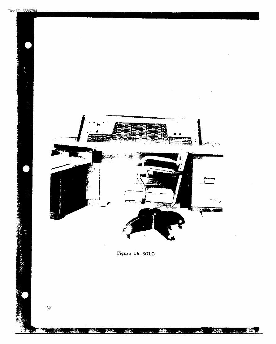
SOLO was composed of a computer console and an inputoutput console (fig. 16) and contained 8,000 transistors, 3,7aO resistors, 200 capacitors, and 8 vacuum tubes.
In spite cf the difficulties, SOLO finally operated very reliably, but original ideas about its use were modified. Instead of many copies being made for operational use, only one SOLO was built, and its use limited to research. For example, it was used as the vehicle· for testing and modify-ing the RCA"Illagnetic tape drives under development for R/D. These three RCA magnetic tape transports had special features to provide flexibilities not available in commercial systems. Of course, this had the effect of extending SOLO storage capacity so that large exper.llnental programs could be run. Also, a Potter tape transport was added to increase SOLO's inputoutput speed. Making these modifications locally, attendant supervision, repairing, and debugging occupied some 35,000 man-hours, spread over s·everal years. Al though much effort and time were devoted to the project to attach and test the RCA tape drives, they never becalne operational because of difficulties and inconveniences in converting from primary input media. However, the Potter drive was quite effective because its tapes were interchangeable with those made on IBM Type 727 tape drives.
Operationally, SOLO programs were written for two purposes: (1) to produce empirical statistics in many problem situations -preced±ng--specia.1-purpose equipment d'es'i'cjn~- 'and (2) to simulate special-purpose equipment during design and construction. SOLO was the first computer extensively used by Agency engineers to assist in engineering logic-check or design optimization.
The original objective of SOLO -- to prove that a reliable operational computer could be constructed using directcoupled transistor logic -- was attained. In August 1963, SOLO was removed from regular oper~tion and turned over to a machine-processing group for t~aining purposes.
BOGART
In Chapter 1, page 4, the problems attending the preparation of input data for computer treatment have been touched on. The difficulties inherent in Agency activities --lack of control of source material, variations in communications practices, rigid formatting requirementF of computer programs -had resulted in the construction of many different types of conversion equipment. In 1952 and 1953, suggestions were made for using espe~ially designed digital computers for data conversion and editing and to "clean up" raw data for input to
31
Doc ID: 6586784
Figure 16-SOLO
32
larger computers. During the NOMAD development, for example, one proposal for the solution of its anticipated111assive data preparation, conversion, and formatting requirements was to build an additional computer for these purposes.
In December 1953, a proposal for the design and construction of such an "editing" computer was approved. The purchase description of BOGARTl specified-a· logical design based upon 7-bit words and provided for magnetic core and magnetic drum storage, punched paper-tape input, punched paper-tape and card output, and a flexible set of 3-word instructions. In July 1954, Engineering Rese~rch Associates Division of RemingtonRand was awarded a contract to build two of these machines. The decision was made to use diode and magnetic core logic for arithmetic and control circuitry: the basic memory cycle time was to be 2 0 micros·econds.
Several months of programming experimentation showed that the small, 7-bit word size and the awkwardness of handling a 3-word group for every instruction caused much difficulty for programmers and put a strain on the memory capacity. In July 1955, a modification was made that provided for several index registers and larger word size (24 bits), with flexibility in dealing with 9-:bit portions of any.--word.-- --Now-,- also,
-- fou:r- machines instead of two were to be constructed and equipped with IBM Type 727 magnetic-tape drives. Serial 1 was delivered in July 1957: Serials 2 and 3, in November 1957: and Serial 4 in January 1958. Subsequently, the pilot model was utilized as the central computer for the remote-operated system ROB ROY, so that five BOGART machines in all were delivered to the Agency.
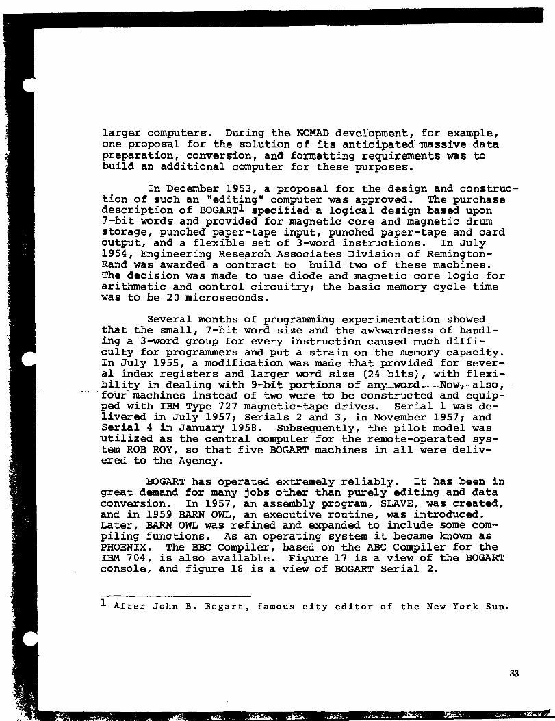
BOGART has operated extremely reliably. It has been in great demand for many jobs other than purely editing and data conversion. In 1957, an assembly program, SLAVE, was created, and in 1959 BARN OWL, an executive routine, was introduced. Later, BARN OWL was refined and expanded to include some compiling functions. As an operating system it became known as PHOENIX. The BBC Compiler, based on the ABC Compiler for the IBM 704, is also available. Figure 17 is a view of the BOGART console, and figure 18 is a view of BOGART Serial 2.
1 After John B. Bogart, famous city editor of the New York Sun.
..... .... . _,
33

Doc ID 4
l.":i~11n-e 1 ·1 -- BOGAH'l\ Console, wil:h lBM 72.'7 '1'aµe urivel::l

4
-----
Figure 18 -- BOGART, Serial 2
······ •• a.,.,.. •••••••• l o•• --~.. .....
~ . . . . . .....
D: 6586784
CUB
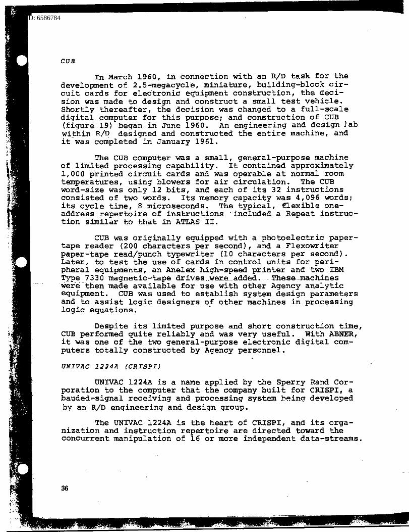
In March 1960, in connection with an R/D task for the development of 2.5-lilegacycle, miniature, building-block circuit cards for electronic equipment construction, the decision was made to design and construct a small test vehicle. Shortly thereafter, the decision was changed to a full-scale digital computer for this purpose; and construction of CUB (figure 19) began in June 1960. An engineering and design Jab wi~hin R/D designed and constructed the entire machine, and it was completed in January 1961.
The CUB computer was a small, general-purpose machine of limited processing capability. It contained approximately 1,000 printed circuit cards and was operable at normal room temperatures, using blowers for air circulation. The CUB word-size was only 12 bits, and each of its 32 instructions consisted of two words. Its memory capacity was 4,096 words; its cycle time, 8 microseconds. The typical, flexible oneaddress repertoire of instructions ·included a Repeat instruction similar to that in ATLAS II.
CUB was orig;i.nally equipped with a photoelectric papertape reader (200 characters per second), and a Flexowriter paper-tape read/punch typewriter (10 characters per second). Later, to test the use of cards in control units for peripheral equipments, an Anelex high-speed printer and two IBM Type 7330 magnetic-tape drives .. were .. added. ·--These-machines
·wer·e ·then made available for use with other Agency analytic equipment. CUB was used to establish system design parameters and to assist logic designers of other machines in processing logic equations.
Despite its limited purpose and short construction time, CUB performed quite reliably and was very useful. With ABNER, it was one of the two general-purpose electronic digital computers totally constructed by Agency personnel.
UNIVAC 1224A (CRISPI)
UNIVAC 1224A is a name applied by the Sperry Rand Corporation to the computer that the company built for CRISP!, a bauded~signal receiving and processing system b~inq developed by an R/D enqineering and design group.
The UNIVAC 1224A is the heart of CRISP!, and its organization and instruction repertoire are directed toward the concurrent manipulation of 16 or lilore independent data-streams.
36

: 6586784
Figure 19.-CUB
.. · . - ··-.. - . ·tit • ·s·. J ·:··~ •.
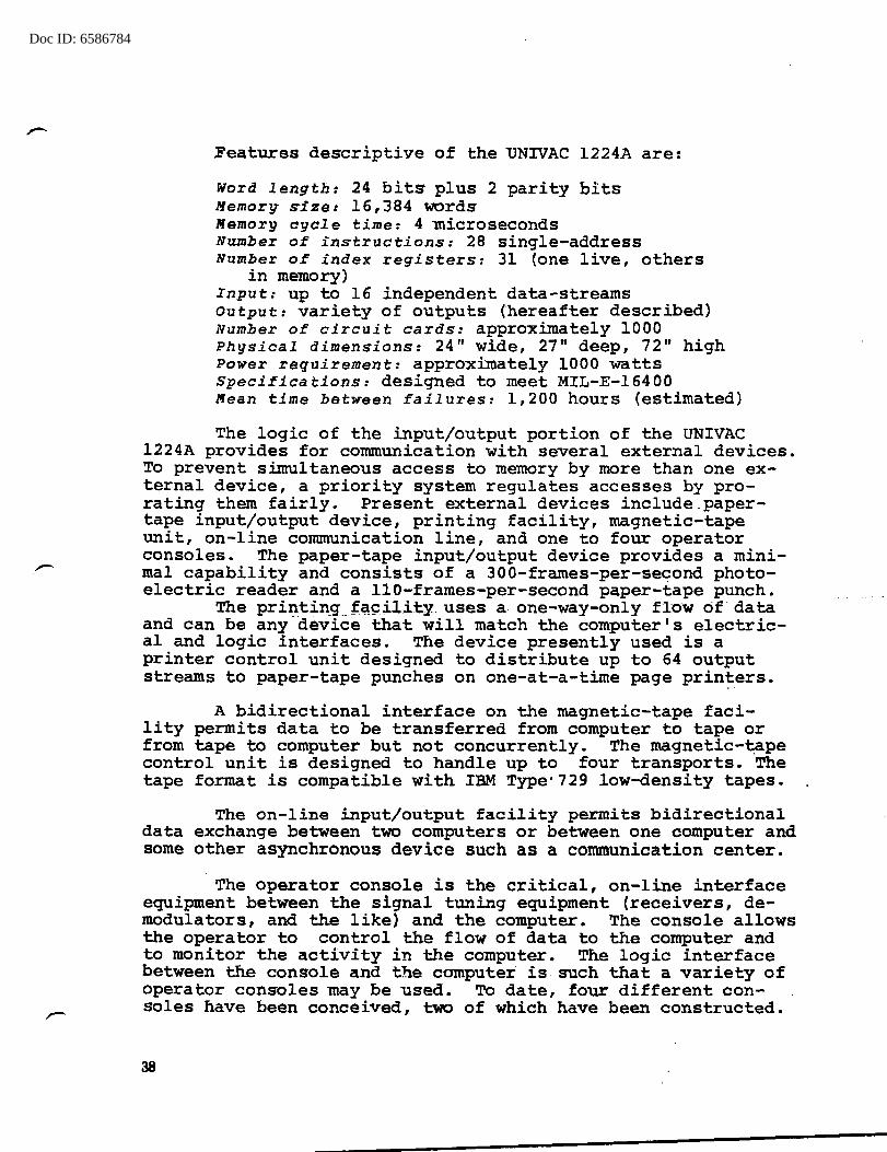
Figure 20.-Partial View of CRISP!, Showing Paper-Tape Input, 37 UNIV AC 1224A, and "B" Console
Doc ID: 6586784
.Features descriptive of the UNIVAC 1224A are:
Word length: 24 bits plus 2 parity bits Memory· s-ize: 16,384 words Memory cycle time: 4 lnicroseconds Number of instructions: 28 single-address Number of index registers: 31 (one live, others
in memory) Input: up to 16 independent data-streams output: variety of outputs (hereafter described) Number of circuit cards: approximately 1000 Physical dimensions: 24" wide, 27" deep, 72" high Power requirement: approximately 1000 watts Specifications: designed to meet MIL-E-16400 Mean time betw·een failures: 1, 200 hours (estimated)
The logic of the input/output portion of the UNIVAC 1224A provides for communication with several external devices. To prevent simultaneous access to memory by more than one external device, a priority system regulates accesses by prorating them fairly. Present external devices include.papertape input/output device, printing facility, magnetic-tape unit, on-line communication line, and one to four operator consoles. The paper-tape input/output device provides a minimal capability and consists of a 300-frames-per-second photoelectric reader and a 110-frames-per-second paper-tape punch.
The printin_g __ J:.;tp.il.ity uses a. one-way-only fl-ow of data and can be any-device that will match the computer's electrical and logic interfaces. The device presently used is a printer control unit designed to distribute up to 64 output streams to paper-tape punches on one-at-a-time page prin~ers.
A bidirectional interface on the magnetic-tape facility permits data to be transferred from computer to tape or from tape to computer but not concurrently. The magnetic-~ape control unit is designed to handle up to four transports. The tape format is compatible with IBM Type·729 low-density tapes.
The on-line input/output facility permits bidirectional data exchange between two computers or between one computer and some other asynchronous device such as a communication center.
The operator console is the critical, on-line interface equipment between the signal tuning equipment (receivers, demodulators, and the like) and the computer. The console allows the operator to control the flow of data to the computer and to monitor the activity in the computer. The logic interface between the console and the computer is such that a variety of operator consoles may be used. To date, four different consoles have been conceived, two of which have been constructed.
38
Doc ID: 6586784
-
Two UNIVAC 1224A computers have been put into use, the first in June ·1963 ·and the second in July 1963. Per~or.mance has- oeen excellent. Four ...more are under construction for delivery early in 1964. Procurement of 10 more for other purposes is being initiated. Figure 20, a partial view of CRISPI, shows the punched paper-tape input unit, the UNIVAC 1224A computer, and the operator console, type B.
HARVEST
The most important characteristic of the stored-program general-purpose, electronic digital computers has been their spectacular versatility -- their general usability for statistical jobs, logical jobs, analytic jobs, and the like. However, because of -the elementary nature of most individual computer operations, this characteristic is often a disadvantage for performing certain specialized operations. In other words, a special-purpose machine can be built with analytic power superior to any general-purpose system, assuming equal states of the engineering art. On the other hand, this superior power has not come easily. Special equipments have well-known disadvantages -- initial delay for specification, design, and construction; possible disappearance of problem requirement; and high cost per machine. Special efforts were made to reduce these disadvantages, to cut down costs and delivery time. In April 1954, a possible solution of this machine designer's dilemma was proposed in FARMER, a system of g~~er~~~E~~pose and special-purpose e~~~~n:!: __ i;h~:t; __ would include suitable provisions for switching, ;:l: control, and data transmission. FARMER would attempt to combine the advantages of both types of equipments, minimizing or eliminating the disadvantages of both, by providing (1) a powerful, general-purpose computer capable of controlling the operation of special-purpose attachments as well as the flow of data through the system, and (2) specialpurpose, high-speed attachments, built and connected as problem requirements dictated. Thus, ntorage, input-output, and statistical requirements of special probli:!Ins could be standardized and provided in the general-purpose portion, leaving only the heart of a proposed special analytic attack to be designed and constructed.
Just about the time that FARMER was being considered, the Agency's efforts to get the large-scale computer system, NOMAD, were reaching a crisis (see page 28, 29). The contract with Raytheon Manufacturing Campany was terminated in June 1954. During that same ·month, an Agency committee assigned to set priorities in equipment planning took up consideration of the FARMER proposal. With current NOMAD difficulties an important factor in its discussions, this committee created an ad hoc study group for the purpose of surveying the Agency's
39
Doc ID: 6586784
,-
needs t:or large-scale analytic equipment and preparing recommendations for design studies. The report of this group, published in Noverciber 1954, approved the 'FARMER proposals and emphasized the following particularly desirable characteristics for the proposed system and its parts:
1. Compatibility and uniformity. 2. An increase in speed as far as practicable. 3. Break-up into separate units that can be freely
interconnected. · 4. Multiple copies of those units that are required
most frequently. 5. Ability to put early units into operation before
other FARMER units are completed. 6. Ability to incorporate new unit-types as their
need appears.
During the next few months, some effort was made to begir. launching a FARMER System. Detailed investigations were conducted to determine what special attachments should be considered, and some high-speed circuitry research was undertaken; but little of a concrete nature really got under way.
In May, and again in· August 1955, IBM representatives contacted the Agency and described their STRETCH program of engineering and logic researches -- researches directed towards development of an advanced computing-.sy.st.em -hav-ing one-
.. hundred to two hundred times the power of the best existing machine. These prospective features were based on the following specific developments:
1. Transistor fabrication and circuitry advances in the 10-megacycle-per-second range.
2. Advanced core-memory techniques showing promise of reaching access times of about one-half microsecond for small memories (about 1,000 words) and two microseconds for larger memories (approx. 16,000 words).
3. Improvements in magnetic-tape handling systems, making the attainment of an information transfer rate of upwards of 1,200,000 bits per second appear practicable.
4. Revolutionary logical design and organization improvements -- program look-ahead, automatic indexing, automatic table lookup, and the like.
IBM representatives explained that the company had invested many millions in the research program but was now too short of funds to build a hardware ·system to test the logic, circuitry, and components. Because of NSA's need for such a
40

Doc ID: 6586784
••
-
large-scale system and because of this Agency's ability to test-operate the system, IBM proposed that the first STRETCH system :Ce :Ouilt and delivered for a fixed price of $3,500,000.
Although Agency technical personnel considered this a great bargain, it was rejected because our engineers were not convinced that the high-speed memory techniques were developed and proven ready to incorporate into a hardware system, and also because Agency requirements for a system of this magnitude justified a special effort to insure that its design was more Agency-oriented. The strong recommendation of the Agency engineers and analysts involved was that these developments should somehow be incorporated into the planned FARMER system. For this reason, after Agency discussion and negotiation with IBM, two 18-month study contracts, SILO and PLANTATION, were awarded to IBM.
Under the R/D study task, SILO, IBM's high-speed memory development was supported to the extent of $821,203. This task was supervised by a nucleus of engineers conducting advanced component researches. These memory developments centered around two approaches that corresponded to the halfmicrosecond and two-microsecond access times -- ref erred to at IBM as the "fast" and "large" memories respectively. The so-called "fast" memory utilized multi-hole cores. At the time, this unique development was considered one of the weakest key components of the proposed system and, therefore, was the principal basis for initiation of SILO.
PLANTATION (later renamed RANCHO) cost $828,340 and ref erred to the design studies that led to the Agency-oriented computer system HARVEST. During the first few months of 1956, the activities under this contract included physical security arrangements, clearances of personnel at IBM, and the creation of an Agency FARMER-HARVEST task force to indoctrinate the cleared IBM personnel in NSA problems and machine needs and to exercise technical supervision. Primarily, the task force described our analytic machine needs and background, and wrote descriptions of typical problems thaf the n9w system would be expected to solve. ·
After a year, work on the high-performance tape system, supported by IBM's limited research budget alone, did not seem to be progressing as well as other hardware developments of the system. Because IBM had no plan to perfect a commercial line of such tape systems, and because NSA, perhaps more than any other computer user, urgently required such a high-performance tape system, another 18-month study contract, TRACTOR, was awarded to expedite this· development. This contract began in
41

Doc ID: 6586784. \.
.r-
January 1957 and cost $337,443. After a period of experimentation with different parameters for such a system, the design goal was set for an automatic cartridge-loading system having approximately 100 ti'mes the speed of the IBM Type 727 tape drives then in use.
On May 1, 1957 IBM delivered the Preliminary HARVEST Manual of Operation, containing proposed logical design for the HARVEST System.
Certain aspects of the situation confronting IBM had a definite influence on the design of HARVEST. Some time before the 1955 discussions with NSA, IBM had submitted proposals (more or less in direct competition with Remington-RandUNIVAC) to the Atomic Energy Commission's Livermore, California facility fo~ the construction of an advanced computer system. The R-R-U design was selected by AEC, and the computer system LARC (Livermore Automatic Research Calculator) was already under way by. 1955~ IBM decided to push its advanced computer researches still more energetically: and its program STRETCH went ahead, with several millions of company research money. After NSA's negative first reaction to IBM's offer to build a computer at a fixed price, AEC's Los Alamos Scientific Laboratory accepted substantially the same proposition. In addition, the desirability of guiding the computer design ·effort so as to result in a commercially-marketable system was of long-range interest to IBM's top management. The subsequent actions to initiate design and memory studies for NSA put .. IBM-in·the difficurt·technical position of being confronted with three possible conflicting courses of action within the same computer research activity: also, their staff of qualified technical people was limited. The·different emphases in the three courses were, briefly:
1. Atomic Energy Commission required extremely high calculation speeds and the ability to solve very large systems of equations and deal with ex- · tremely large numbers. .
2. Emphasis in NSA was on very large volumes of input data to be processe4 rather than high-speed calculations, the ability to perform complex logical operations on t'WO streams of data at high speeds, and extreme versatility in attacking Agency problems of great variety.
3. Computers for the commercial market required somewhat less advanced capabilities in calculating speed and volume of data to be processed, but greater emphasis on economy and reliability.
To arrive at.a satisfactory solution to this trilemma, IBM created a committee of senior computer design experts,
42
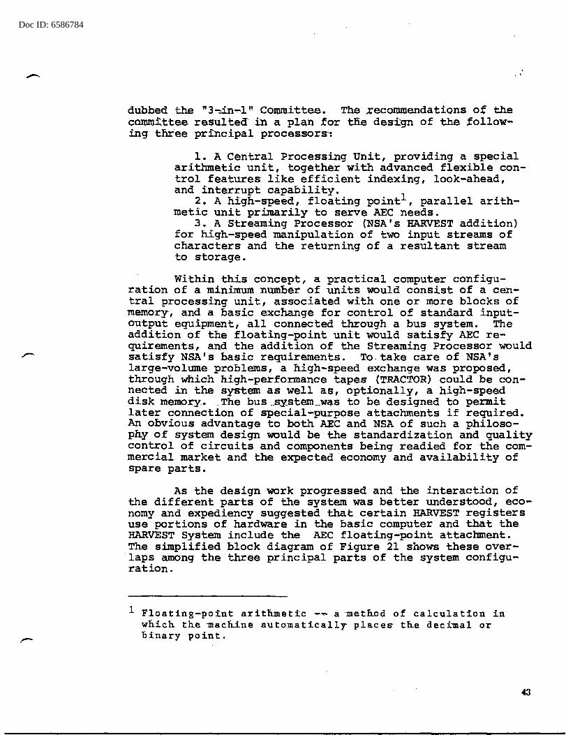
Doc ID: 6586784
dubbed the "3-::i.n-l" Committee. The .recommendations of the camm~ttee resulted" in a plan for tJ:ie des·i:gn of the following t:nr·ee principal processors·:
1. A central Processing Unit, providing a special arithmetic unit, together with advanced flexible control features· like efficient indexing, look-ahead, and interrupt capability.
2. A high-speed, floating point1 , parallel arithmetic unit primarily to serve AEC needs.
3. A Streaming Processor (NSA's HARVEST addition) for high-speed manipulation of two input streams of characters and the returning of a resultant stream to storage.
Within this concept, a practical computer configuration of a minimum number of units would consist of a central processing unit, associated with one or more blocks of memory, and a basic exchange for control of standard inputoutput equipment, all connected through a bus system. The addition of the floating-point unit would satisfy AEC requirements, and the addition of the Streaming Processor would satisfy NSA's basic requirements. To.take care of NSA's large-volume problems, a high-speed exchange was proposed, through which high-performance tapes (TRACTOR) could be connected in the system as well as, optionally, a high-speed disk memory.. . _The bus .. sy.stem __ was to be designed to permit later connection of special-purpose attachments if required. An obvious advantage to both AEC and NSA of such a philosophy of system design would be the standardization and quality control of circuits and components being readied for the commercial market and the expected economy and availability of spare parts.
As the design work progressed and the interaction of the different parts of the system was better understood, economy and expediency suggested that certain HARVEST registers use portions of hardware in the basic computer and that the HARVEST System include the AEC floating-point attachment. The simplified block diagram of Figure 21 shows these over-laps among the three principal parts of the system configuration.
1 Floating-point arithmetic ......... a meth.od of calculation in which the ~acliine automatically place~ th.e deci~al or binary point.
43
Doc ID: 6586784)
lligh-Speed Memory
2 banks, 1024 words each 0.9 microsec. access time
~~~ --~~-
INPUT OU'l'PUT
EXCHANGE
(To Input-Output Units)
-
FWATING POINT
ATTACHMENT
)
Lafl.'e Memory - 6 bank11, 16,384 words each 2.18 microaec. accell8 time
BUS SYSTEM
CENTRAL PROCESSING
UNIT
I r- -.L..--1 I Special j I Purpose I Attach men ta I L - --- __ _J
HAIWES'I' ATl'ACHMEN'l'
-
I
I I I I I I
_ _J
- -
HIGH SPEED
EX CHAN OE
)
-

Doc ID: 6586784
After the submissi.on of the HARVEST desi,gn proposal in May 19.57 1 an ad hoc group to eyaluate HARYEST was created, consisting of 14 programmers and tfu:'ee engineers drawn from research and operational parts of the Agency. This group studied the design proposal and Eade rough time estiniates for the execution by· HARVEST of 15 problems considered representative of Agency needs in this category of equipment. In most of these, a comparable estimate for doing the job by another computer or special-purpose machine was also prepared. The report of the group, aated 31 July 1957, indicated that HARVEST would be faster than the equipment currently used and, in most cases, by factors varying hetween r~o and 200. Where sorting predominated, the estimated factor of speed increase over the IBM Type 705 ranged from 50 to 100. Members of the ad hoc group also made several suggestions for design improvements. A later evaluation, dated 3 January 1958, included comments on the reasonableness of the IBM cost quotations and a discussion of estimated efficacy of alternative equipment combinations. It also recommended initiation of both contractual and local efforts towards the creation of a sophisticated programming system.
In April 1958, the formal purchase description for HARVEST was presented to-IBM. The RANCHO study task had been extended until June 1958, and the provisions of the purchase description were worked out by personnel of NSA and IBM. This purchase description included several improvements over the origina.l. HARVEST-· design proposal. Two 1-etter- contracts,-based upon IBM cost estimates and later converted to def initive contracts, were drawn up for the design and construction of the HARVEST System; they were ratified by IBM on 30 April 1958.
A number of revisions of the original proposal were made during the design and construction of HARVEST. A full account of the succession of changes was made as a part of the Contractor's final report. Comment on several key features of the system as it was delivered in January 1962 is sufficient here.
The ·original high-speed (0.5 microsecond access time) memory development was based upon the use of a special 3-hole core as the basic storage element. This project was abandoned in May 1960 because it could not be completed in time for inclusion in the finished system. In place of the 3-hole core memory, another memory scheme, known as "2-D" was substituted; it used two toroid cores per bit. Completed and installed in the system, access time in the fast niemory is about 0.9 microsecond. Still greater speed is possible by
45

Doc ID: 6586784
-
overlapping meroory references between. the t~ 1,024-word banks so that an effective ·access time of approximately 0.5 microsecond i.s obtained. The large memory access time of 2 .18 microseconds is substantially at its original 2-microsecond goal. Orders were placed for four additional 16,384-word banks, so that a total of six times 16,384, or 98,304 words of large memory were installed. As in the case of the high-speed memory, overlapping memory references among the six banks of large memory can make the effective access time substantially shorter.
The character streaming time in the stream processing unit, originally set at 0.2 microsecond, finally became 0.3 microsecond. In the basic computer, the time necessary for typical arithmetic operations is also longer than was originally planned. The high-performance tape system TRACTOR has· met all its original goals. In addition, the overall TRACTOR storage capacity has been doubled by increasing the number of cartridges available at each automatic cartridge handling unit from 80 to 160. The HARVEST System delivery date of January 1962 was about 15 months later than the original target date, and the cost of the system exceeded the original estimate by about 32 percent.
Because of HARVEST's unique position in NSA~history, a semi-technical description of its principal features has been included here. Obviously, a full technical treatment is beyond the scope of this effort;;_ however_, an attempt is- -made-to giy~ _a pictur~ of--HARVEST __ that shows its similarities to and differences from conventional computers. Figures 22 through 29 are views of the principal portions of HARVEST.
HARVEST MODES OF OPERATION
Primarily because of the actual hardware overlap among portions of the Central Processing Unit (CPU) and the HARVEST attachment (HPU), the system operation is said to be in ~ither the l\.rithmetic mode or the Streaming m~de.
Arithmetic Mode
In this mode the system operates similarly to conventional computers -- that is, generally instructions indicate operations to be performed on data specified in terms of 64-bit words with "addresses." In HARVEST, however, the addresses can indicate not only any word in core storage but any desired number of bits, beginning at any specified bit position; that is, a serial arithnietic unit is provided which operates on fields of data of varyinq length. The kinds of arithmetic operations possible include integer operations performed in
46
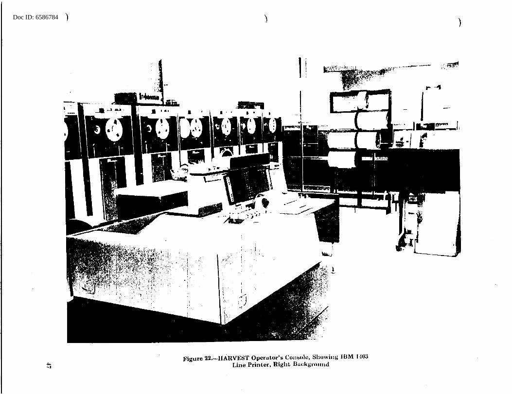
Doc ID: 6586784 ) )
1
Figure 22 .. --HARVEST Operator's Console, Showing IBM l-to:J Line Printer, Right llackgrnund
)
:·. t'!lr'1
. !-~
iL ----

Doc ID: 6586784)
c !:'·
..
)
Figure 2 3 -- Showing General View, ating Area, Background HARVEST OT~:~TOR in Left
)
____ _.,...,_

Doc ID: 6586784
-
T a;· !ISL ~~~ .. -·f'··'~j·, f·~ 7~,~
~-~> ........ _
-
Figure 24.-HARVEST Maintenance and Engineering Consoles: (1) Arithmetic and Logic Unit (left) (2) Streaming Unit (right)
49
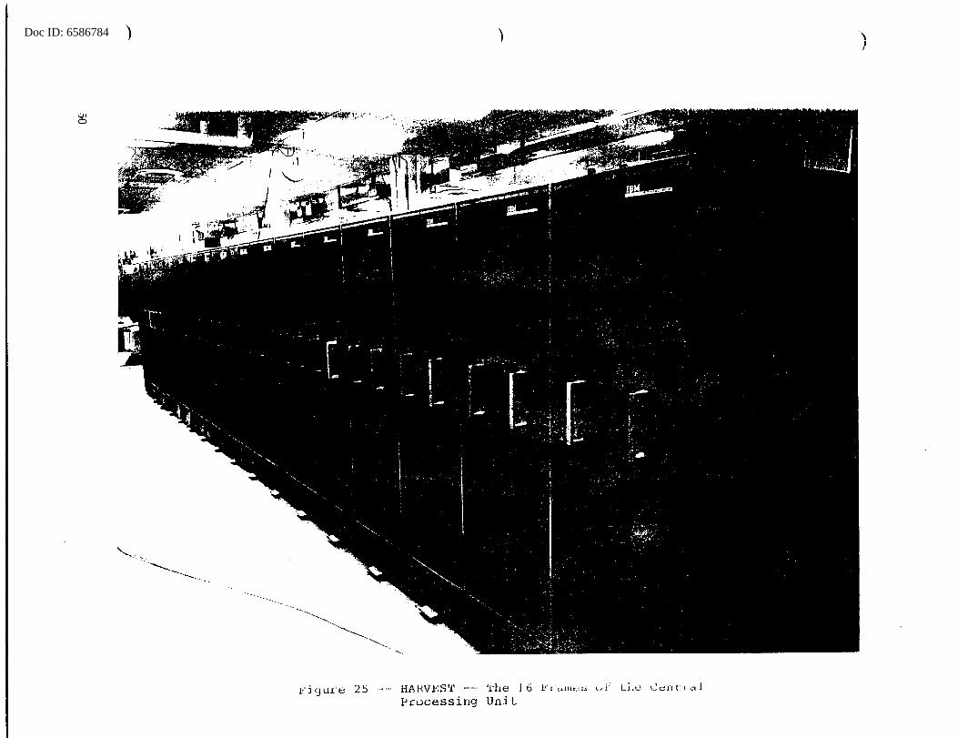
Doc ID: 6586784 ) )
1:'ic3ure 25 -- HAH.VES'l' --- '!'he 16 Processing UniL
Li.c
\
'
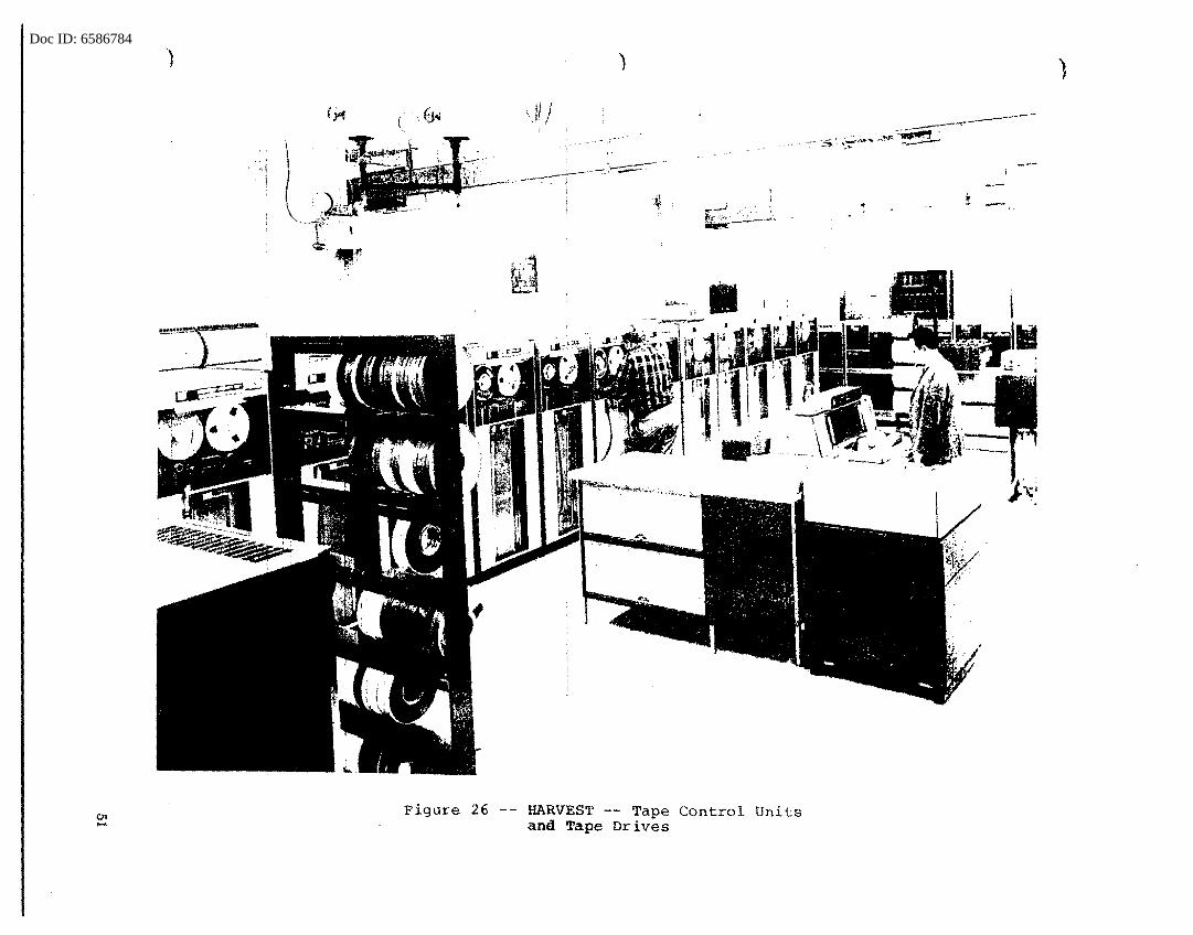
Doc ID: 6586784)
Figure 26
)
1
~~· . I
~-L
-- HARVEST __ T ana Tape Dri~~: Control Units
), ,

Doc ID: 6586784 ) ) )
Figure 27 -- HARVEST 'l'he 6 Large Memories

Doc ID: 6586784
...
Figure 28 -- HARVEST -- One Unit of the Fast Memory 53
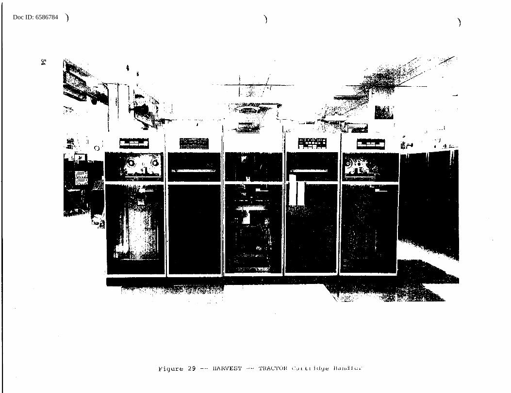
Doc ID: 6586784 ) )
f '
~~~ '''
: I
--~-
__ I
- ,,. ;
I ! ' I '
Figure 29 --- HAf<.VES'l' --· 'l'l{AC'l'Ol< <'.Jl Li. id<Je llau'11e1"
Doc ID: 6586784
either binary or decimal representation, radix conversion operations (decimal-to~inary- or binary-to-decimal conversion}, connective operations (paired bit combinations), and parallel floating-point arithmetic operations.
The operation of the Instruction Unit (I-Unit) and the look-ahead Unit (LA-Unit) represents the most important logical advance of P..ARVEST's arithmetic mode over conventional computers. This advance exists primarily because of the virtual elimination of waiting time caused by imbalance between fetching, storing, indexing, and execution times. The I-Unit fetches and indexes instructions, loads the LA-Unit, and monitors storage addresses, interrupt operation, time clock operation, and operator console control. The LA-Unit makes possible the overlapping of fetching of data from core storage with instruction fetching, modification, and execution. An important part of this· process is the insuring by the LA-Unit that errors in data transmission and instruction executions are caught and corrected and tha't the state of interrupted operations is monitored and restored if necessary.
Streaming Mode
The HARVEST Processing Unit (HPU) has been characterized as the initial implementation of the FARMER principle. That is, it can be considered to be a special-purpose attachment operating under control of a general-purpose computer and sharing the same input-output and storage- ·facil-ities. - -It violates the basic FARMER principle, however, in that portions of it are built as integral parts of the basic computer and therefore are not detachable.
On page 22, mention was made of the influence of ABNER's "swish" instruction on the HARVEST stream unit design. In both these machines, the requirements were similar to those of a file-maintenance operation. A file of data must be updated from time to time, by deleting incorrect information, inserting or adding new data, and making calculations or transformations. In both ABNER and_ HARVEST, the innovation was the provision for a simultaneous accessing of two streams of data from storage, performing selected operations and delivering to storage a single result stream of data. Naturally, HARVEST's HPU is considerably more sophisticatec1. logically than ABNER'S "swish" as well as using basically higher speed circuitry. The following paragraphs briefly discuss some of the ways in which. the HPU operates on data-streams.
The HPU uses two source units, P and Q, that correspond to the two input streams of characters, and a "sink" unit, R, that corresponds to a result stream. Figure 30 is a simpli-.
55
Doc ID: 6586784 )
BUS, from Memory
p Indexing
Unit
64 64
Register P
Switch Matrix
BUS, from Memory
Q Indexing
Unit
H Indexing
Unit
BUS, to Memory
RegisterQ
Switch Matrix
Switch Matrix
Register R
8
8
8
Mask
Mask
Mask
Match Station
Match Station
Match St~tion
)
LOGIC UNIT
Indexing
Indexing
Statistical Accumulator
Statistical Counter
Fi~ure 30.-HARVEST Streaming Data Paths
Table Addresn
Assembler
Table Extract
Unit
Thre;hold
)
Tables, Cow1tera, Existence
(stored in
Memory)
Match Station
Doc ID: 6586784
f ied representation of the data-paths of the HPU and shows the principal units and their relationships. P and Q fetch 64-bit data-words from core storage ana process the data through a switch ·matrix (syv') tflat selects and requlates the release of individual bytesl for subsequent processing in other parts of the HPU. Byte masks (BM) at outputs of P and Q and input to R permit ordinary bit IDasking. Match stations (MS) act as monitors to detect occurrences of specified preset characters or errors during stream processing. The four match stations -- at outputs of P, Q, the Logic Unit (LU), and the Table Extract Unit -- are capable also of inserting a substitute or corrected byte into the stream without delaying the stream process. The Logic Unit combines two 8-bit input bytes in any of 32 possible combinations. The LU can also generate several one-bit stimulus signals to be supplied to several possible strategic positions in the HPU ana used for control, interrupt, and status indication. Modular and other arithmetic transformation operations that generate an output stream of characters are performed in the LU. The statistical counter ("SCTR} is used to count any of a number of stimuli generated in various units in the HPU that have been set to react to specific conditions. Associated with the counter is a register that stores a threshold. Because an output of SCTR can be entered directly into result-stream R, events or reactions t~ .. ey~p.ts occurring_ 4'?-!.~ng streaming can affect subsequent cycles of this stream. The statistical accmnulator (SACC) receives 8-bit or 16-bit fields from the Logic Unit or the Table Extract Unit. Both algebraic and absolute value accumulation are available, and stepping-by-one can be done under control of setup or adjustment. Also, a threshold can be set with generation of a one-bit stimulus when the threshold is reached or exceeded by the total in SACC.
Before describing the Table Reference Unit, a brie~f explanation of table look-up as implemented by conventional computer techniques may be helpful. The technique of table look-up is one of the most interesting, powerful, and versatile tricks widely used for years by programmers on conventional computers. Lists of employees~ names or numbers, telephone directories, ordered collections of various sorts are a few examples of "tables" or files which must be consulted and operated upon. Because gaps in such alphabetically or numerically-ordered data are inevitable {and unpreCl.icta:!"ll~), a
1 byte -- a group of 1 to ~ bits
57

Doc ID: 6586784
,-
straightforward process for finding individual entries is apt to be p:roh.J.bitively time-consuming. The problem. is further complicated because typically each job involves use of an unknown or uncontrolled stream of data to be examined. The principle underlying the p:rogrannning solution to such situations involves a system for utilizing the individual data items themselves to create the address in memory where the applicable extraction or insertion must be made. Typically, the· combination of a data item with some constant would form the address which is inserted into a skeleton instruction. Such a "machine-made" instruction would then be ready to be called into Control for execution. The whole process, more or less as described here using conventional instructions, is far more efficient than a hrute force approach which examines memory contents, one at a time.
In the Table Reference Unit, this whole process is performed automatically under program setup control. A Table Address Assembler (TAA) provides a means of adding bytes from either the P-stream or the Q-stream to a designated 26-bit table base address. The resulting sum may be used in instructing storage to perform look-up, countl ~- or existence! functions. The other i~portant use of an address formed in this manner is to extract information from words in core storage, using the TEU, and send the information to the match unit and logic unit, and if desired, to the R sink 1,lni~ ___ and.. _the statistical accumu-lator (SACC). Other. useful functions are served by TEU;for ex-ample, in connection with indexing. ·
Indexing and Setup -- The 'what' rather than the 'how' of arithmetic and streaming modes have been briefly discussed. A feature of both modes, of importance, is indexing and, especially in HPU, the setup words. In the arithmetic mode, the Instruction Unit performs indexing as in most modern conventional computers; that is, addresses are modified prior to their execution. The programmer may specify this as an addition of the value of the index word to the operand address (normal) or by use of the index value itself as the effective address (progressive). In the streaming mode, however, index-ing is much more complex. By means of parameters placed in specified fields of a series of 20 setup words, the determination and regulation of sizes of bytes, the extent of overlap (if any) among successive bytes, the nature and length of cycles, and the definition of successive levels are all made auto-
1 See Special Memory Features, page 59
58

Doc ID: 6586784
matically. The index control uni.ts generate three basic types of patterns for parameter manipulation -- sequential, nested, and triangular. In the sequential type, each level of indexing is in control only once and is a reading level; i.e., at a given level, indexing controls the readi.ng or storing of bytes. In the nested type, each level has control many times, but only the first level is a reading level. The triangular type, on each succeeding iteration of the level, decreases or increases by one the nwnber of iterations that the particular level performs.
Streaming Instructions -- As mentioned, HPU instructions are preceded by setup words. The principal streaming instruction that governs byte-by-byte operation is the Stream Byte-by-Byte instruction (SBBB); this instruction itself contains additional parameters. Most of these parameters refer to gates (not shown in Figure 30) that govern data paths among the elements of the HPU and the bus. In addition to the byte-by-byte streaming operations, HARVEST provides the following six "hybrid" instructions, so called because they are not byte-by-byte yet apply to the HARVEST concept of streaming:
SMER SSER SILS SSEL STIR SQNL·
Stream Merge Stream Search Stream Indirect Load or Store Stream Select Stream Take-Insert-Replace Sequential Tabl-e- Lookup
Adjustments -- An adjustment unit monitors non-arithmetic operations and, upon the detection of certain stimuli, interrupts the normal operation and initiates special operations. These special operations modify the basic indexing pattern or temporarily vary the basic process. Adjustments may be used by the programmer to perform operations that cannot be performed entirely by the control circuitry of an ·individual unit. Adjustments can be used to terminate setup instructions, but usually normal non-arithmetic operations are resumed as soon as the special operations are completed.
Special Memory Features -- Among the features originally specified during design studies were capabilities in core storage that would facilitate making frequency distributions "'.rith a minimum of programming and housekeeping steps. These requirements were fulfilled by the three· features known as clearing, counting, and existence.
1. The clear feature is useful even without the other two. It permits large areas of core storage to be set ·to 2ero rapidly. In the fast (O. 9-micro-
59

Doc ID: 6586784
second) memory, either 32 or 256 consecutive addresses can be cleared to zero with one instruction. The large (2-microsecond) memory can be cleared in blocks of 128 or 512 consecutive words with a single instruction.
2. The count feature, available only in the fast memory, allows a 1 to be added to a given bit-position. Several variations of count instructions permit the accumulation of numbers with a choice of maximum sizes of 8, 16, or 24 bits. The count feature, used in conjunction with TAA and TEU, is a powerful and rapid facility for preparing frequency distributions.
3. The existence feature permits the mapping of large sections of memory so as to represent the fact of existence by the state of individual bit positions. Thus, much greater capacity is available to record the status of large data files, for example, if only a 'yes' or 'no' fact is required for each group. In an existence operation, available in both classes of core storage, a 1 is stored at the selected bit-position regardless of the present contents of that position.
TRACTOR
When it was decided to initiate the TRACTOR study contract in January 1957, a primary consideration was to bring the effective-speedup-over current magnetic-tape-systems c-loseto the speed increase of the rest of the system~ that is, TRACTOR tapes would have about 100 times the speed of IBM Type 727 magnetic tapes. An additional important requirement was a·need for the capability of handling massive volumes of data in problem situations not amenable to attack by any other means. The researches at IBM had pointed the way to such a capability, but additional emphasis was necessary to bring these tape studies up to the same level as other parts of the proposed system.
By May 1957, the date of submission by IBM of the original HARVEST design proposal, the broad out-lines of the TRACTOR System and certain of its specifications were set. Even though the contractor encountered numerous difficulties during-the following two or three years, the TRACTOR portion of HARVEST finally met or exceeded most of the original detailed specifications. A description of the principal characteristics follows.
There are three automatic cartridge handling units, each of which has facilities for automatically seeking and extracting a specified cartridge from its position in two storage units under program control. Each cartridge is mounted on a ·
60
Doc ID: 6586784
,,.... .. tape transport and automatically threaded and positioned for information transfer. Each of six storage units has a capacity for storing a maximum of 80 cartridges, and each cartridge handler serves two tape transports. The instantaneous information-transfer rate of a tape transport is 1,128,000 8-bit characters per second. This rate is based upon a packing density of 3,000 bits per inch on 1.75-inch-wide tape, 22 tracks across (16 data bits, 6 check-bits}, and tape motion at 2.35 inches per second. The total system capacity, that is, the volume of data automatically available from storage (maximum of 480 cartridges}, is approximately 44 billion! characters. Figure 23 shows the TRACTOR automatic cartridge handling units in the left background, and Figure 29 is a close-up view of one TRACTOR cartridge handling unit.
HARVEST OPERATIONAL SYSTEM {HOPS)
When, in May 1957, IBM submitted their HARVEST design proposal, some of their personnel time was released from RANCHO (the system design study contract}. However, because both NSA and IBM recognized that an automatic programming system was a prerequisite for successful operation of the HARVEST equipment, the RANCHO study was extended and provision made for part of IBM's effort to be devoted to laying the foundation for such a system. Later, in September 1958, a continuatipn ot:_thi_s __ ~f.t'_o_rt was _provided for under __ a __ new task, FARM BOY. IBM personnel at first proposed to create a system of programmjng for HARVEST that would be, in effect, a consolidation of work done in connection with the AEC STRETCH system with FORTRAN2, together with necessary additions to satisfy other needs. Consideration of the effects of such an approach produced the decision that more emphasis was required on data-processing operations, and especially on particularly analytic operations.
Meantime, the need for definition of the kind of system required, the classes of data to be dealt with, and specialized operations to be performed led to establishment of the
1 Because of bad spots, interrecord gaps, and parity characters, this approximation amounts, on the average, to 50 percent of the usable tape space.
2 A widely used programming language created in 1956 by IBM
61

Doc ID: 6586784
task CORN CRIB. In July 1~59, a newly-established staff group began work on~aprogramming system for HARVEST. The initial effort in this new group resulted in creation of specifications for an advanced language. The newly specified language was called ALPHA (Advanced Language for Pro-gramming HARVEST) . - -
In February 1960, in an attempt to reach a satisfactory basis for a division of effort, NSA and IBM specialists met in conference. The following decisions were reached:
1. Because many ALPHA features were too sophisticated to be implemented in time for the delivery of HARVEST, a "minimum system" should be created.
2. The writing of the specifications for the various parts of the programming system should be apportioned as follows:
IBM: Machine· Control Program (MCP) HARVEST Assembly Program (HAP) Executive, or HARVEST Control Program (HCP)
NSA: Generalized File Operators (GFO) Job Request Language (JRL)
In May 1960, NSA's part in this arrangement had been completed, but because of personnel and training difficulties, IBM was not ready with the HCP and MCP specifications. The decision was made that NSA··-should --continue with· the specifications of HCP, leaving MCP and HAP with IBM. By August 1960, about 35 IBM personnel were implementing ALPHA, using as a basis the NSA-produced ALPHA Language Technical Report that was issued in June 1960, and the specifications for HAP were accepted.
In March 1961, a new task order, CLAGHORN, was signed that provided for the implementation of the HARVEST Assembly Program, the Machine Control Program, and the ALPHA Compiler (also by IBM). The total contract cost,· including all pre-vious FARM BOY costs, was to be $2,189,000, and the work was to be completed by July 1963. CLAGHORN was later extended until 30 November 1963. The actual production of the programming system was a joint NSA-IBM effort, with many of the decisions and conventions arrived at in conference and with subsequent production of different portions of the work assigned to one or the other of the two working g~oups.
A HARVEST program is ordinarily written using one of four programming languages that occupy different hierarchical levels within HOPS. To some extent, statements from more than one language can be.intermixed in a program. These languages, listed in order from the lowest (close to machine language) to the highest (close to problem language) are:
62

Doc ID: 6586784
,,,,....- .
HAP (HARVEST Assembly Program) Autocoder (Macro-instructions) ALPHA (Advanced Language for Programming HARVEST) JRL (Job Request Language)
Because HAP really uses a system of mnemonics for the HARVEST instructions and merely converts these symbols into binary form on a one-for-one basis, such programs are potentially the most efficient, but they are also the most tedious to prepare. In fact, no practical programs are written using HAP alone. Autocoder, the next level of language above HAP, uses a system of statements of common logical functions (macro-statements). A language-processing program converts these statements into symbolic form and then, just as for HAP, into binary machine language. In practice, the combination of HAP and Autocoder, called HAP III, is so commonly used that it is considered a single level of language.
In ALPHA, the highest level for preparing a HARVEST program, the programmer uses English words in referring to a sequence of logical operations upon data described as logical units of information. ALPHA has been designed to create programs very rapidly, compared with HAP and Autocoder, and in addition can include statements in these languages. The ALPHA compiler translates the programmer's statements into machine language, going through a succession of passes.
Finally, requests for jobs on HARVEST must use a pro-.. -·cedure-oriented external command language~-- JRt.-~ .. ----rii'-Eb_e_·-Jab
Request Language, the requester directs the entire HOPS complex, including the HOPS Control Program (HCP), input arid output functions, data specification, library of programs, and individual functions in HAP or ALPHA. The actions called for in JRL are carried out by a series of control programs that form the foundation for HOPS. The philosophy of HOPS is based upon an operational cycle that processes work as much as possible in batches. A HOPS cycle, a collection of job requests, varies according to the amount of wo~k and volume of data involved.
The TRACTOR Tape System plays an integral role in HOPS operation. All data files, sys.tern control programs, and problem programs and procedures are stored on TRACTOR tapes. To facilitate problem programming for the job requester, the data involved in each problem are organized into sets of logical records, called logical files, that can be referenced by name, independently of detailed quantities and locations. The manipulation of files, including specification of individual subsets of logical files and maintenance of records and catalogs, is done by a pa~t of HOPS called TRACTOR File Maintenance. Input to the whole system is performed by way of IBM Type 729 high-density tapes that contain blocked files prepared on a
63
Doc ID: 6586784
1401 computer in the HARVEST complex and are loaded through HARVEST onto TRACTOR tapes. The output function is handled in similar fashion. Output data is structured by the HARVEST program before recording on 729 tapes. After removing such tapes, printing of results, if required, is accomplished by using the 1401 with a line printer.
All problem programs available to the job requester are either generalized file operators (GFO's) or special-purpose programs. GFO's perform most of the common data processing functions, and each has available a number of variations in parameter specification. As the name indicates, special-purpose programs are written for operations too specialized for GFO's. Additions to both classes of programs will continue to be made as the HOPS system grows.
In summation, HARVEST, as a hardware system, is probably the most logically sophisticated computer in existence, and even though based upon the 1956-57 state of the engineering art, it is also one of the fastest computers in operation. Because of the HARVEST system's logical complexity, the HOPS effort, itself a massive undertaking, has imposed certain conventions to enable large numbers of programmers with a small amount of training to prepare jobs for HARVEST that can deliver results within a relatively short total elapsed time. Of course, sustaining programs that were written during the early HARVEST experience can be refined if the additional effort is justified. ~-inally, the whole operational programming s.yatem_ ___ _ is designed to be open-ended, and even though the HARVEST complex has not yet been used to its fullest potential, HOPS will grow and improve as the individual sponsors and programmers gain experience.
64
Doc ID: 6586784
,,-.
CHAPTER 3 COMMERCIAL COMPUTERS
As the cormnercial computer industry grew and requirements became better defined, more computers became available to attack profitably specific types of Agency problems. Commerc~al computers, grouped according· to the builder and ranging from the simplest, desk-sized equipments to the most sophisticated machines, are discussed in the following pages. Several of these machines are better adapted for computation with a small quantity of input and output; others are designed to handle large volumes of data, using little computation; and some are particularly well-suited for use in combination with other computers or with special-purpose attachments. Those used as remote-operated systems are treated separately in Chapter 4.
INTERNATIONAL EUSINFSS MACHINES CORPORATION
IBM-701
When, in 1952, IBM announced plans for building twenty "Defense .. ··· Calculators," -NSA---was--among the first to place an order. This action was natural because of the Agency's long and successful use of IBM punched-card equipment. The Defense Calculator (renamed the EDPM Type 701) featured binary arithmetic and one-address instruction logic, two instructions per word. Each word of its high-speed, 4,096-word, electrostatic-tube-type memory was 36 bits long. The 701 also included a slower drum memory of 16,384 words and card and magnetic-tape input-output devices. In later 701 models, magnetic core memories were substituted for the electrostatic tubes.
The 701 was delivered in April 1953. Many operational · jobs being run on standard punched-card equipment or on ATLAS or ABNER were programmed for the 701 to provide flexibility in choice of available equipment.
Operating experience with the 701 revealed a number of weaknesses in the system as well as inadequate Agency preparation of programs and operating procedures. First, because no off-line, card-to-tape preparation facility existed, much valuable computer time was consumed during card input of data. Operations involving large-scale use of the magnetic tape were
Doc ID: 6586784
plagued by failures because of faulty reading or recording on magnetic tape. Humidity control in the machine area was critical; but whether magnetic-tape errors were primarily due to this or to undependable read-write electronics would be difficult to determine. However, there were some instances of successful operations of large jobs, some involving several hundred reels of magnetic tape. The overall operations of 70l's internal computation on problems requiring limited data input or minimizing magnetic-tape operations was excellent. The 701 was retired in December 1955.
IBM-702
Soon after the 701 was operational, IBM announced a new line of data-processing equipment. The EDPM 702 used a binary-coded decimal rather than a pure binary number system in its arithmetic unit and operated upon variable-length fields rather than words. It was planned with emphasis upon commercial and accounting operations involving large streams or lists of numerical or alphabetic material. NSA's machine processing people recognized its applicability for its large-volume indexing and data-manipulation requirements and placed an order. The 702 was delivered in the spring of 1955.
The machine processing organization created a separate group to prepare for programming and operation of the 702. This group undertook the preparation of 702 programs to replace_ most of the standard.--punched.,,card-procedures for largevolume data-handling jobs. Preparation of indexes, large-scale data conversion, various types of specialized.dictionary preparation are a few examples of large j"obs-for which the 702 was considered suitable. The 702 was retired in April 1956.
IBM-705
Within a year after the installation of the 702-, IBM announced a new machine, the Type 705, as a replacement for the 702. The 705 was an improvement over the 702 because it had a large core memory, a faster arithmetic unit, and was generally better engineered. In addition, it had the ability to operate input-output equipment simultaneously with computation. Requirements had increased to such an extent that the acquisition of five of these machines seemed feasible. These were delivered, one in May 1956, one in January 1957, two in September 1957, and one in February 1961. The first two were returned to IBM in November 1962 and April 1960, respectively. Retirement of the remaining three 705's begins in March 1964.
The 705's have made an impressive record of useful service in the many jobs included in the class of data processing. D'ARTAGNAN, generalized four-way sorting, is particularly worth
66
I._

Doc ID: 6586784
mentioning. This program, regarded as one of the most efficient sorting programs, has been made available to other agencies. Also, the 705 installation made the first large-scale, practical use of TRANSEMBLER, a procedure whereby large numbers of full-scale programs were assembled on magnetic tape for systematic processing. Figure 31 is a general view of the 705, and Figure 32 shows the 705 core memory.
Because of the great number of IBM 727 magnetic-tape drives associated with a multi-705 installation, a switching system was proposed that would make connection possible between any tape drives and any 705 tape control units. Fewer tape drives would be needed with such a system, thus possibly balancing the cost. Because no such switching system was available commercially, the R/D group was requested to design and construct one. SINBAD was completed in November 1957. It made possible the switching between a maximum of 15 Type 727 magnetic-tape units and the control units for the printers, card readers, card punches, and tape drives associated with the several IBM 705 data-processing systems. In Figure 31, the set of manual switches and controls for SINBAD can be seen just to the right of the console.
IBH-704
Coinciding with the introduction of the 705, IBM announced its new Type 704 as a replacement for the 701. Al_though_.the. 704 had the same basic--logical orga-nizatio.n as the 701, its arithmetic unit and core storage were faster, and its design provided additional features such as index registers and logical arithmetic. The first 704 system was delivered to the Agency in January 1956 and was operational in one week. The second 704 was delivered in February 1957. Both were equipped with 4,096-word core storage. The third system arrived in September 1957 and contained- 32,1-68 wrc;:>rd s of core storage. Subsequently, the storage size of the first two systems was increased a~so -- to 32,768 words.
The 704 systems proved to be much more reliable than the 701, as well as superior in capacity, speed, and logic. Also, operations involving much magnetic-tape manipulation were more practical because tapes were interchangeable among the 704's, 705's, and off-line conversion equipments. The first 704 was retired in August 1962, and the second and third in July 1963. Figure 33 is a general view-of the 704, and Figure 34 shows the 704 core memory.
IBM-650
The IBM-650, a medium-speed computer with magnetic drum memory, was delivered in December 1958. Its memory was sup-
67
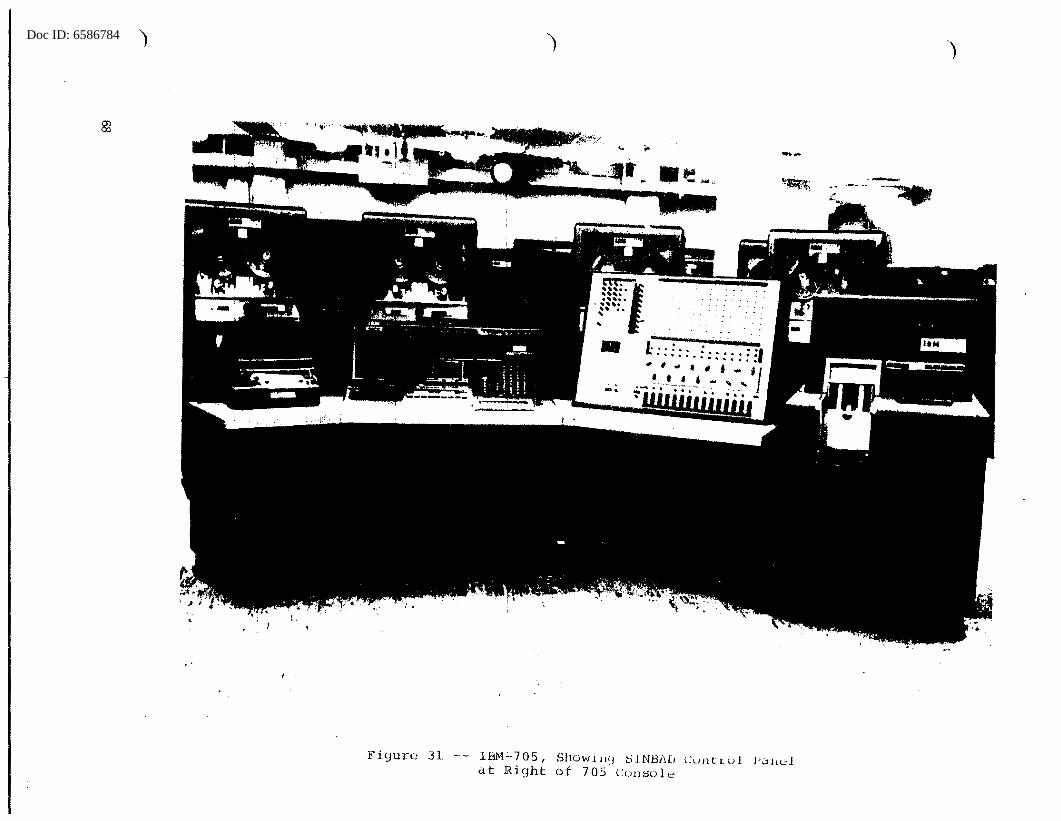
Doc ID: 6586784 )
'.
E'igure 31 -- IBM.:...705, Shuwi11'.J SJNJ:3A[J Cunltol l'CJ!lt;;l at Right of 705 corisolt!
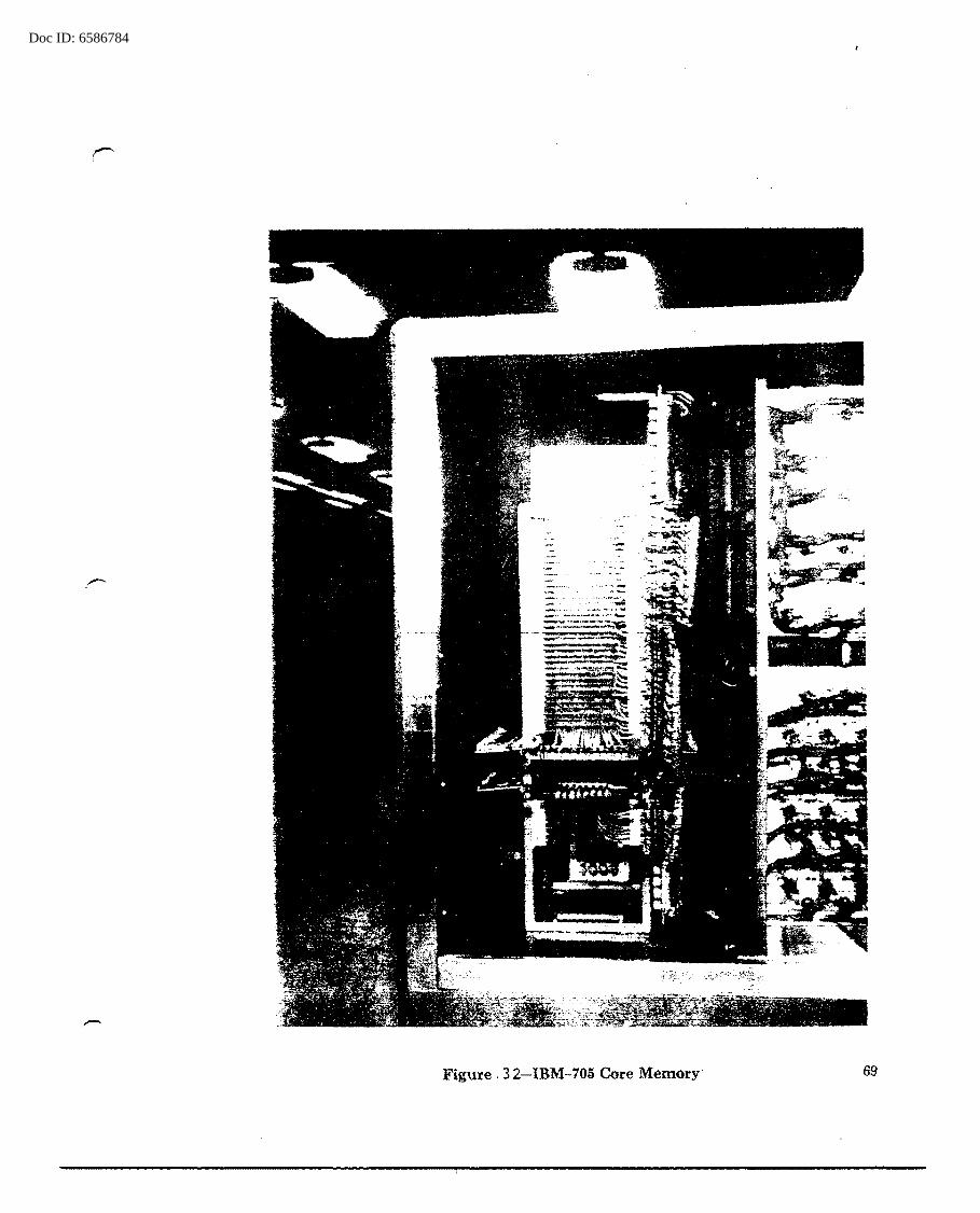
Doc ID: 6586784
Figure. 32-IBM-705 Core Memory 69
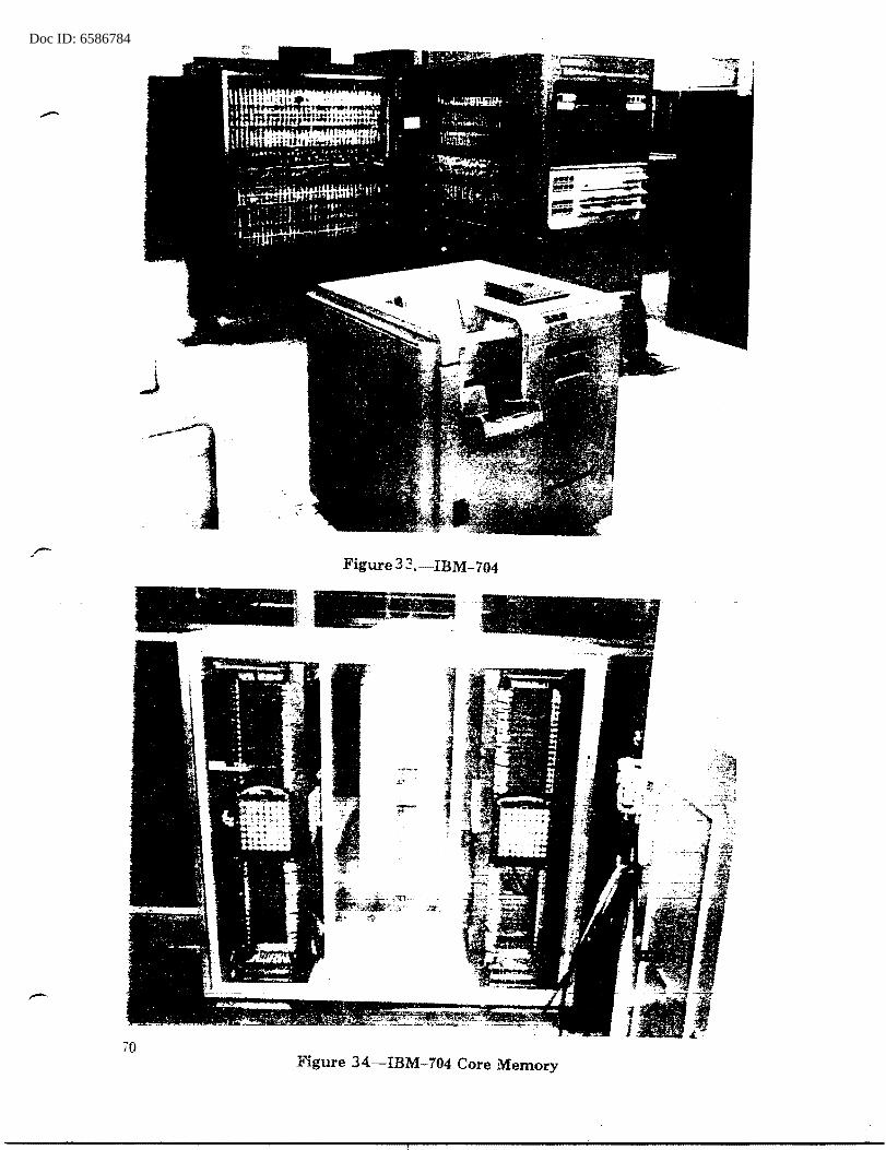
Doc ID: 6586784
Figure 3 3 .-IBM-704
. ,_ ·': ,... .. - ...
... --.:~
70 Figure 34.-IBM-704 Core Memory
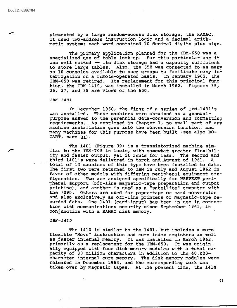
Doc ID: 6586784
plemented by a large random-access disk storage, the RAMAC. It used two-address instruction logic and a decimal arithmetic system: each word contained 10 decimal digits plus sign.
The primary application planned for the IBM-650 was a specialized ·use of table look-up. For this particular use it was well suited -- its disk storage had a capacity sufficient to store large tables. Also, the 650 was connected to as many as 10 consoles available to user groups to facilitate easy interrogation on a remote-operated basis. In January 1962, the IBM-650 was retired. Its replacement for this principal function, the IBM-1410, was installed in March 1962. Figures 35, 36, 37, and 38 are views of the 650.
IBM-1401
In December 1960, the first of a series of IBM-140l's was installed. These machines were obtained as a generalpurpose answer to the perennial data-conversion and formatting requirements. As mentioned in Chapter 1, no small part of any machine installation goes into the conversion function, and many machines for this purpose have been built (see al~o BOGART, page 31).
The 1401 (Figure 39) is a transistorized machine similar to the IBM-705 in logic, with somewhat greater flexibility and faster output, yet it rents for less. The second and third 1401 's were delivered in March and .. Augus.t- of- .196-1.. A
·· total of 13 machines of this type have been installed to date. The first two were returned to IBM in July and August 1962 in favor of other models with differing peripheral equipment configuration. Two are assigned specifically for HARVEST peripheral support (off-line magnetic-tape preparation and output printing), and another is used as a "satellite" computer with the 7090. Others are used for paper-tape or card conversion and also exclusively as off-line printers of magnetic-tape recorded data. One 1401 (card~input) has been in use in connection with communications security since September 1961, in conjunction with a RAMAC disk memory.
IBM-1410
The 1410 is similar to the 1401, but includes a more flexible "Move" instruction and more index registers as well as _faster internal memory. It was installed in March 1962, primarily as a replacement for the IBM-650. It was originally equipped with four disk-memory modules with a total capacity of 80 million characters in addition to the 40,000-character internal core memory. The disk-memory modules were released in December 1963, and the corresponding work was taken over by magnetic tapes. At the present time, the 1410
71
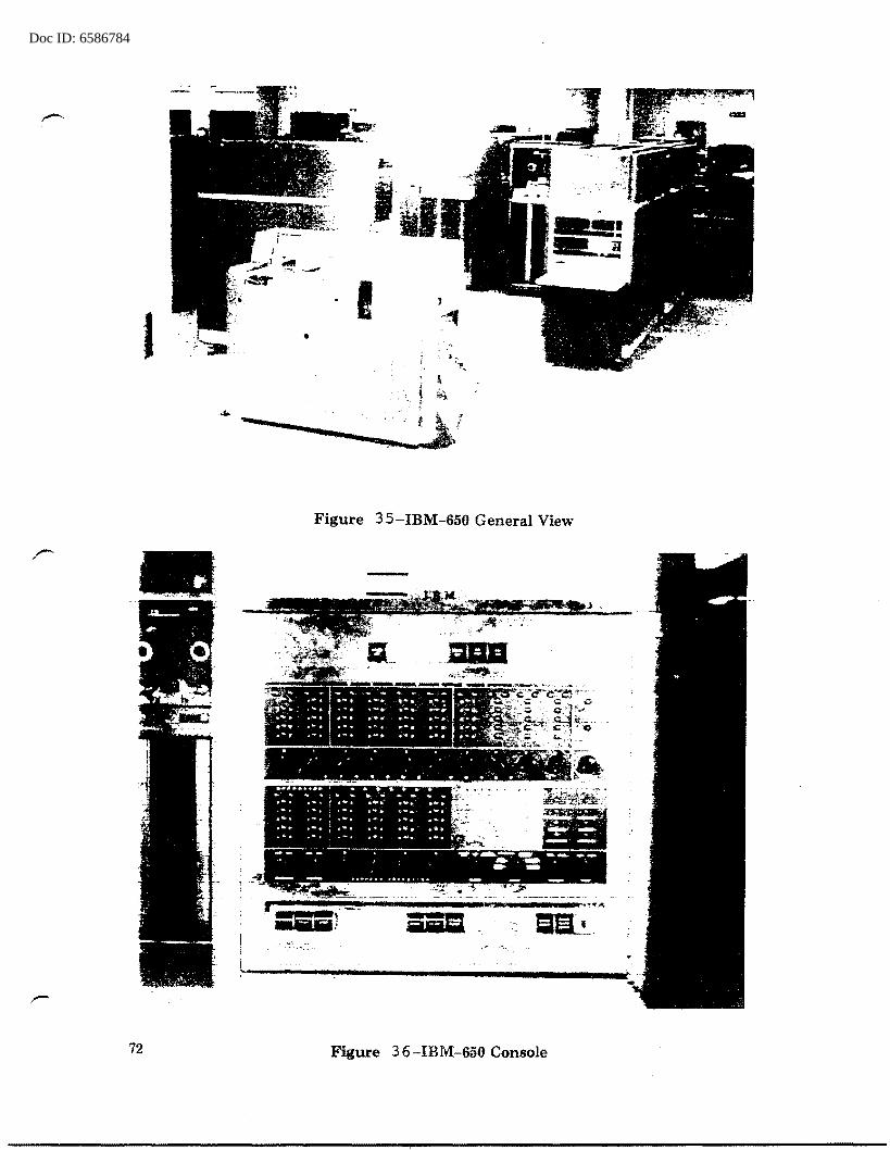
Doc ID: 6586784
I •
.....
•
72
'··--~:.,; ' ·. 1 ·
I
Figure 3 5-IBM-650 General View
Figure 36-IBM-650 Console
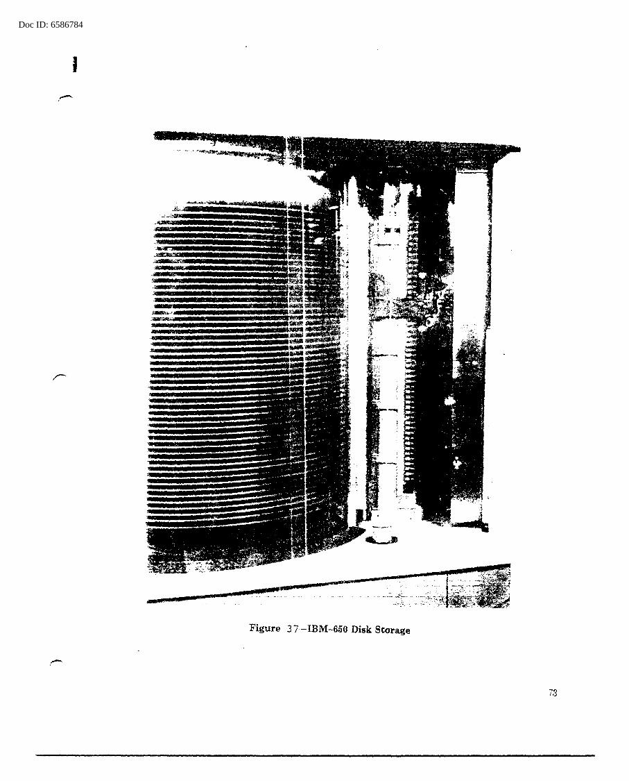
Doc ID: 6586784
I
I
: :: : : >!!
Figure 37-IBM-650 Disk Storage
73
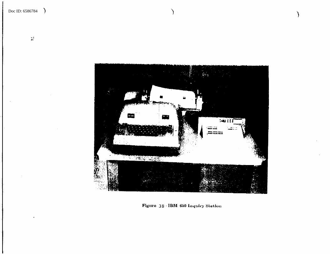
Doc ID: 6586784 )
1;;;;~
\===
Figure 3 8 - IBM 650 11itt ofry Stu tfou
)

Doc ID: 6586784 ) ) )
Figure 39 IBM 1401
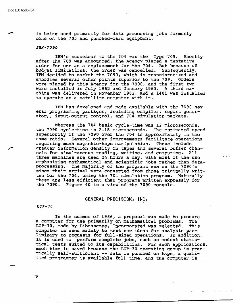
Doc ID: 6586784
is being used primarily for data processing jobs formerly done on the 705 and punched-card equipment.
IBM-7090
IBM's successor to the 704 was the Type 709. Shortly after the 709 was announced, the Agency placed a tentative order for one as a replacement for the 704. But because of budget limitations, the order was cancelled. Subsequently, IBM decided to market the 7090, which is transistorized and embodies several other points superior to the 709. Orders were placed by this Agency for the 7090, and the first two were installed in July 1962 and January 1963. A third machine was delivered in November 1963, and a 1401 was installed to operate as a satellite computer with it.
IBM has developed and made available with the 7090 several programming packages, including compiler, report generator,, input-output control, and 704 simulation package.
Whereas the 704 basic cycle-time was 12 microseconds, the 7090 cycle-time is 2.18 microseconds. The estimated speed superiority of the 7090 over the 704 is approximately in the same ratio. Several other improvements facilitate operations requiring much magnetic-tape manipulation. These include greater information density on tapes and several buffer channels for simultaneous reading, writing, and computing. All three machines ar~ _ u_sed_ 24 _hours a day, with most of· the- use emphasizing mathematical and scientific jobs rather than dataprocessing. The majority of the programs run,on the 7090's since their arrival were converted from those originally written for the 704, using the 704 simulation program. Naturally these are less efficient than programs written expressly for the 7090. Figure 40 is a view of the 7090 console.
GENERAL PRECISION, INC. LGP-30
In the summer of 1956, a proposal was made to procure a computer for use primarily on mathematical problems. The LGP-30, made by Librascope, Incorporated was selected. This computer is used mainly to test new ideas for analysis preliminary to requests for full-sized operations. In addition, it is used to perform complete jobs, such as modest statistical tests suited to its capabilities. For such applications, much time is ~aved because the LGP-30 operating group is practically self-sufficient -- data is punched on tape, a qualified programmer is available full time, and the computer is
76
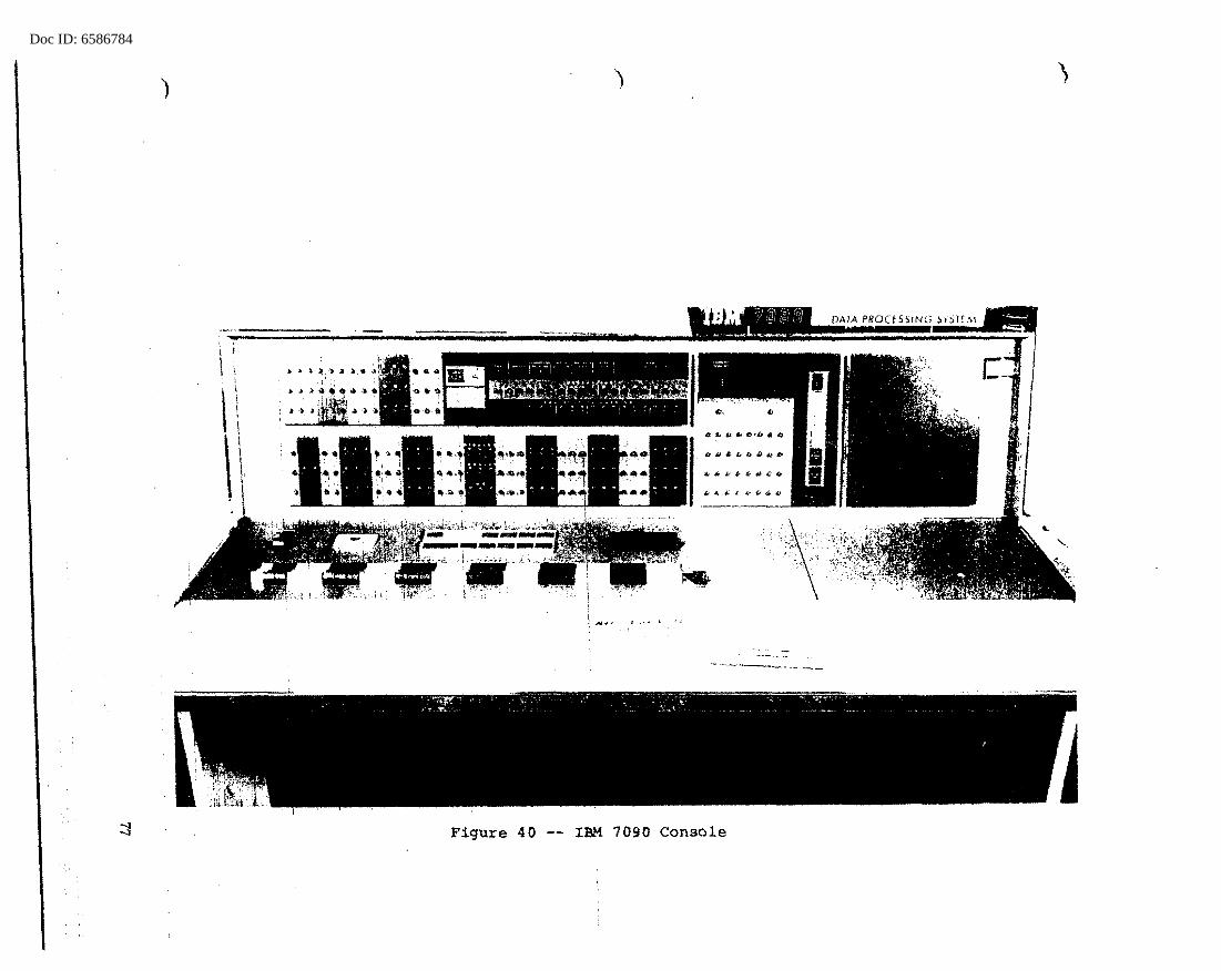
Doc ID: 6586784
)
DATA PROCESSING ~lSlf.'1.1
··---~
Figure 40 -- IBM 7090 Console
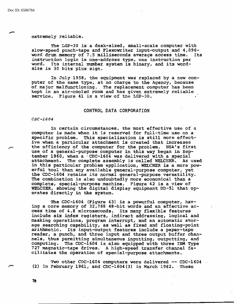
Doc ID: 6586784
extremely reliable.
The LGP-30 is a desk-sized, small-scale computer with slow-speed punch-tape and Flexowriter input-output and 4,096-word drum memory of 7.5 milliseconds average access time. Its instruction logic is one-address type, one instruction per word. Its internal ·number system is binary, and its wordsize is 30 bits plus sign.
In July 1958, the equipment was replaced by a new computer of the same type, at no charge to the Agency, because of major malfunctioning. The replacement computer has been kept in an air-cooled room and has given extremely reliable service. Figure 41 is a view of the LGP-30.
CONTROL DATA CORPORATION
CDC-1604
In certain circumstances, the most effective use of a computer is made when it is reserved for full-time use on a specific problem. This specialization is still more effective when a particular attachment is created that increases the efficiency of the computer for the problem. NSA's first use of a general-purpose computer in this way began in September 1960, when a · CDC-1604 was delivered with a special
--attachment. The complete assembly is calred WELCHE-R. · - As used in this particular problem application, WELCHER is a more powerful tool than any available general-purpose computer, yet the CDC-1604 retains its normal general-purpose versatility. The combination is also undoubtedly more economical than a complete, special-purpose machine. Figure 42 is a view of WELCHER, showing the digital display equipment DD-51 that operates directly in the system.
The CDC-1604 (Figure 43) is a powe.rful computer, having a core memory of 32,768 48-bit words and an effective access time of 4.8 microseconds. Its many flexible features include six index registers, indirect addressing, logical and masking operations, program interrupt, and an automatic storage searching capability, as well as fixed and floating-point arithmetic. Its input-output features include a paper-tape reader, a punch, and three input and three output buffer channels-, thus perrni tting simultaneous inputting, outputting, and computing. The CDC-1604 is also equipped with three IBM Type 727 magnetic-tape drives. A high-speed transfer channel facilitates the operation of special-purpose attachments.
Two other CDC-1604 computers were delivered -- CDC-1604 (2) in February 1961, and CDC-1604(3) in March 1962. These
78
Doc ID: 6586784 ) ) )
J
•
Figure 41 -- LGP-30
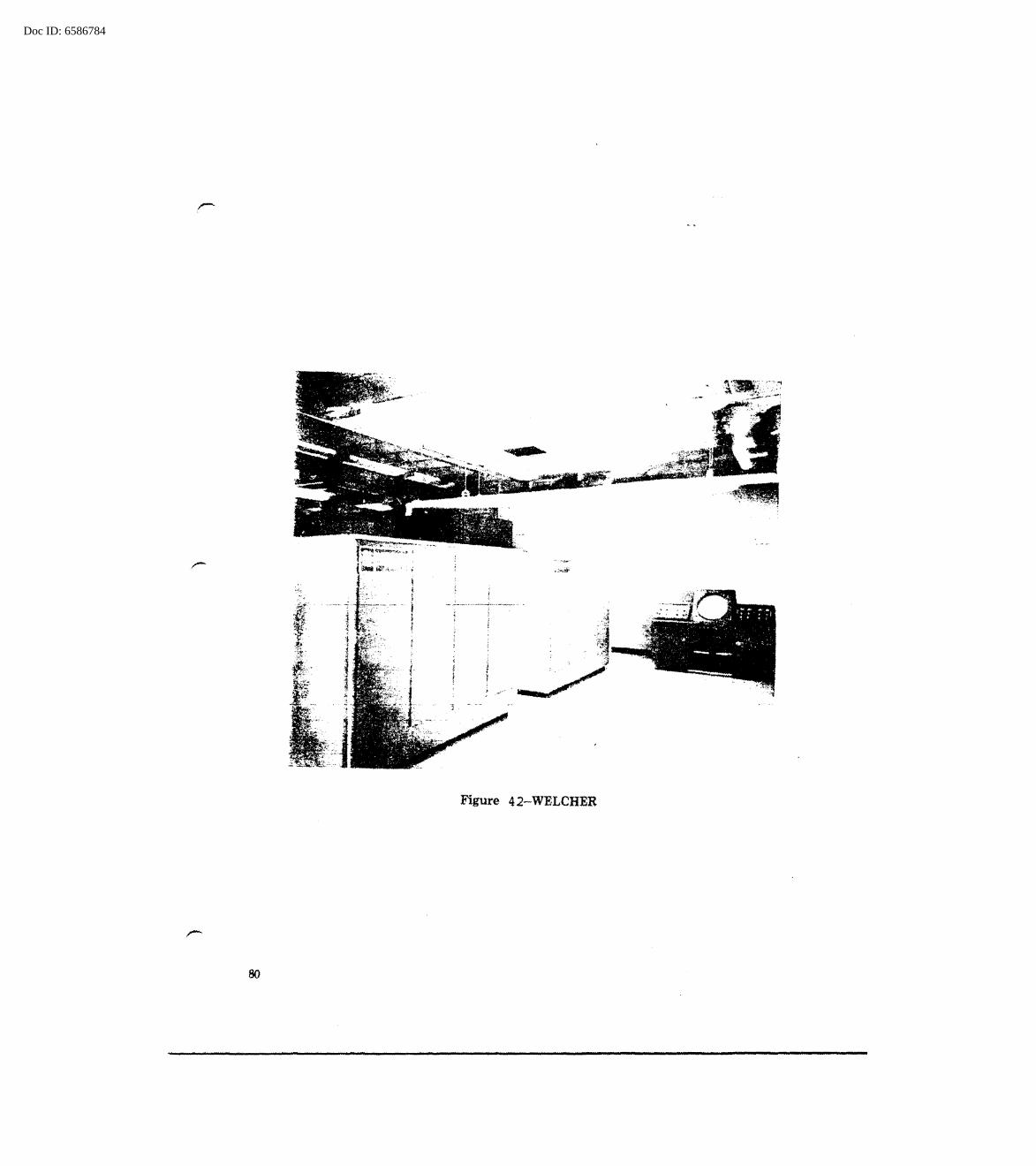
Doc ID: 6586784
80
F'~--r•~+ ..
I (
I l
l l { I 'l
l r ~
·"-'
Figure 42-WELCHER
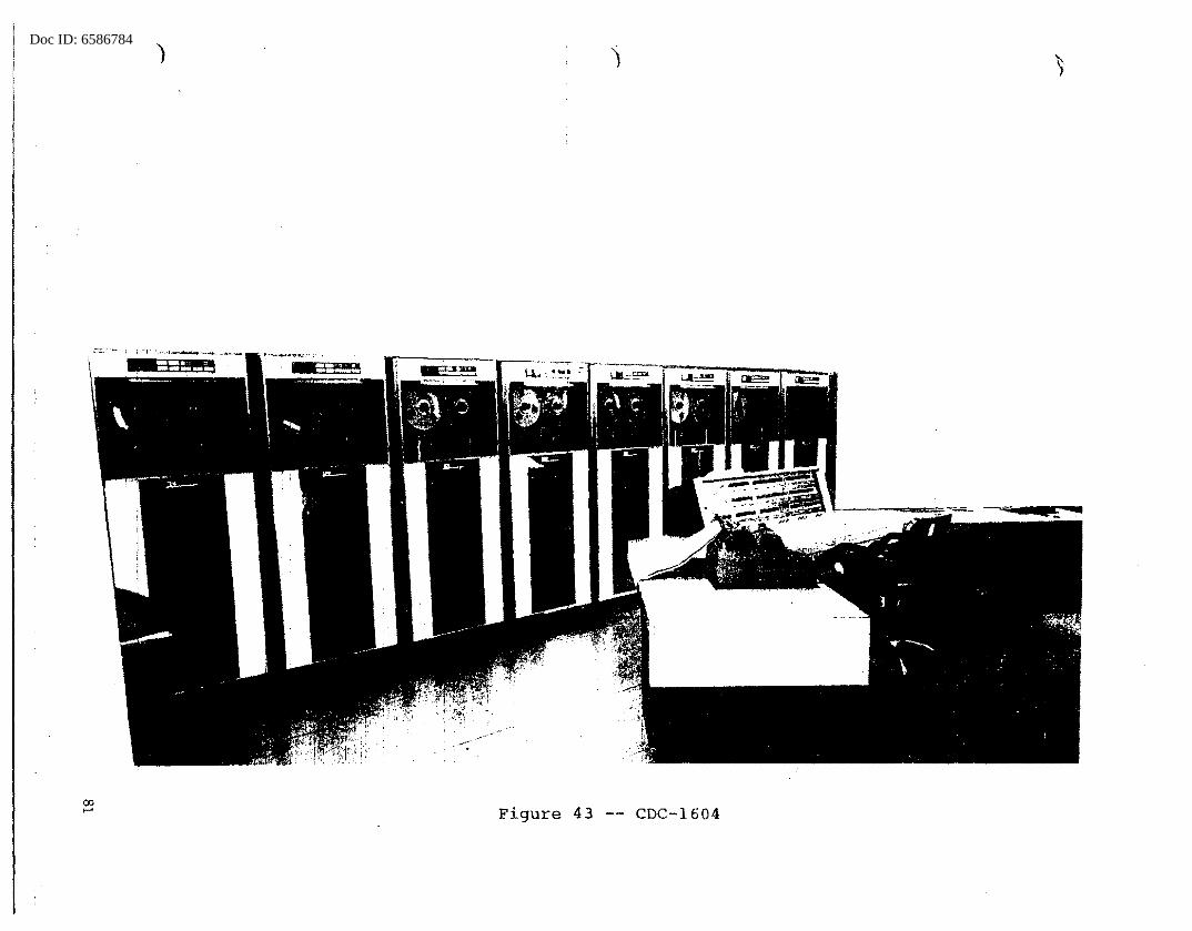
Doc ID: 6586784)
Figure 43 -- CDC-1604

Doc ID: 6586784
machines have each been equipped with eight IBM Type 729-IV magnetic-tape drives, and in addition the CDC-1604(2) has a special data display device, the DD-51. Except for this change and their lack of special attachments, they are identical to the 1604 of WELCHER.
PULLMAN, installed in January 1963, includes a fourth CDC-1604 and a special-purpose attachment. It is equipped with four IBM Type 729-IV magnetic-tape drives. It is also equipped with the special data display device, the DD-51. The two computers, 1604(2) and 1604(3), are further equipped with an additional powerful instruction, the "77" Order. By selecting suitable patterns of ones and zeros, tremendous numbers of variations of transmissive and arithmetic operations can be called into play, involving CDC-1604 arithmetic registers and index registers. This instruction increases their flexibility for analytic applications.
The increasing demand by research personnel for computer time and the difficulty of their competing with operations users has resulted in the establishment of a special research computing facility. The CDC-1604A was selected, and in July 1963 the Agency's fifth CDC-1604 was installed. It has a 1,000-line-per-minute printer, a 'card reader, and 10
I"""' magnetic-tape drives.
The research computing facility is operated as an "open- shop•t-- operation as far as programnfirfg Ts concerned-;- an.a-an interesting arrangement whereby users can deliver programs by tube or by messenger has been evolved. A supervisor program has been refined so that it not only compiles programs written either in FORTRAN or ALGOL, but regulates true concurrent input-output, tape-to-printer, and internal computation. Also, a unique feature of this facility is the so-called "bidder" system for regulating priorities and maintaining records of machine time assignments. According to this system, individual users actually bid for machine time, using their own evaluation in relation to their overall monthly allocation. The machine itself maintains the system records and issues reports to users and supervisors. overall system operation stresses quick turn-around. Normally users can expect a maximum delay of 30 minutes from the submission of a program to delivery of the result, including debugging jobs.
CDC-l60A
The CDC-160A (Figure 44) is a desk-sized, general-purpose computer in a price range low enough to be practical for many data-conversion_ uses and yet sufficiently powerful and flexible for use in real-time and control applications. It uses 12-bit words that are available in groups of 8,192 up to a max-
82

Doc ID: 6586784
. ·~ -- _, • ·:~:r ... ·····~· "t-7 .................. ~;~ .... .
Figure 44 -Control Data 160-A Computer
33
Doc ID: 6586784
imum of 32,768 words. Typically, the instruction word consists of a 6-bit function code and 6-bit execution address. Provisions for specifying more than 64 individual addresses include the use of modifying registers that make available two additional modes of addressing -- indirect and relative. Also available are several other rather specialized modes of addressing. The storage cycle-time is 6.4 microseconds. One hundred and thirty flexible instructions are available;these make the CDC-160A very versatile for data-manipulation. The machine is equipped with a high-speed paper-tape reader and punch, a buffered input-output channel, and an interrupt feature.

Doc ID: 6586784
CHAPTER 4 REMOTE-OPERATED COMPUTERS
For years analysts have yearned for desk-top or deskside machines that could relieve some of the drudgery that always accompanies creative activity. In 1942 the Navy had built a number of copies (including several for the Army} of the NCR Calculator, a desk-top, adding-machine-like device that facilitated tests requiring the use of non-carrying addition. Other analyst-aids have been built for other purposes. These, together with desk calculators and various types of reference tables just about summarize the mechanical help that analysts had available for their personal use. Attempts to build more elaborate equipment for use in analysts'· areas were usually discouraged because of expense, excessive noise, or difficulty in maintenance.
The satisfaction of the analyst's need for personal machine support without many of the disadvantages usually associated with operating a computer installation finally took the form of a remote-operated computer, one of the first in the country. Three such projects are discussed. A fourth, the IBM-650, was also used remotely, but its use was limited to only one class of interrogations; it has been discussed separately (page 71} .
ROGUE (ALWAC IIIE)
In February 1954, investigations were started by the research organization, with the assistance of operational personnel, to determine the feasibility of satisfying the need for more sophisticated machine assistance for analysts by a system of remote operation. Under a research task, AUTOMAT, two approaches were studied. The first was TOTALIZER, a limited-purpose device designed to make comparisons, counts, and calculations of relevant stati·stics from streams of data on punched tape.l The second, ROGUE (Remotely Operated GeneralUse Equipment} , proposed to use a small-scale, general-purpose
1 An engineering model of TOTALIZER was constructed, but in October 1957, before its design was completed for outstation use, the machine was placed in operation. It was used profitably for some months, but never as remote-operated equip· ment.
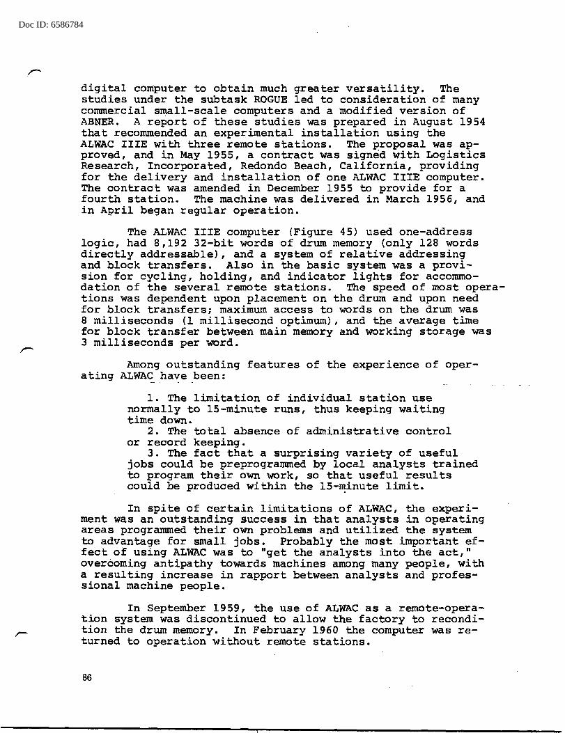
Doc ID: 6586784
digital computer to obtain much greater versatility. The studies under the subtask ROGUE led to consideration of many conunercial small-scale computers and a modified version of ABNER. A report of these studies was prepared in August 1954 that recommended an experimental installation using the ALWAC IIIE with three remote stations. The proposal was approved, and in May 1955, a contract was signed with Logistics Research, Incorporated, Redondo Beach, California, providing for the delivery and installation of one ALWAC IIIE computer. The contract was amended in December 1955 to provide for a fourth station. The machine was delivered in March 1956, and in April began regular operation.
The ALWAC IIIE computer (Figure 45) used one-address logic, had 8,192 32-bit words of drum memory (only 128 words directly addressable), and a system of relative addressing and block transfers. Also in the basic system was a provi-sion for cycling, holding, and indicator lights for acconunodation of the several remote stations. The speed of most operations was dependent upon placement on the drum and upon need for block transfers; maximum access to words on the drum was 8 milliseconds (1 millisecond optimum), and the average time for block transfer between main memory and working storage was 3 milliseconds per word.
Among outstanding features of the experience of operating ALWAC have been:
1. The limitation of individual station use normally to 15-minute runs, thus keeping waiting time down.
2. The total absence of administrative control or record keeping.
3. The fact that a surprising variety of useful jobs could be preprogrammed by local analysts trained to program their own work, so that useful results could be produced within the 15-~inute limit.
In spite of certain limitations of ALWAC, the experiment was an outstanding success in that analysts in operating areas programmed their own problems and utilized the system to advantage for small jobs. Probably the most important effect of using ALWAC was to "get the analysts into the act," overcoming antipathy towards machines among many people, with a resulting increase in rapport between analysts and professional machine people.
In September 1959, the use of ALWAC as a remote-operation system was discontinued to allow the factory to recondition the drum memory. In February 1960 the computer was returned to operation without remote stations.
86
Doc ID: 6586784
'l
I I j,, 1-.\
. 45 -- ALWAC IIIE Figure
Doc ID: 6586784
,,.......
. r-
ROB ROY (BOGART)
In February 1957, another report was prepared by the research group that contained recommendations for a final ROGUE system. Amon·g the comments on the ALWAC opera ting experience, the following disadvantages were cited:
1. Slow speed (1 to 17 milliseconds per order) 2. Limited addressable memory (128 words) 3. F~tremely slow input-output (10 char./second)
However, recognizing the overall success of the ALWAC experiment and the enthusiasm of the analytic groups, the report reconnnended an improved system that included the following principal features:
1. A BOGART computer 2. A buffer system for magnetic tapes 3. A buffer scan unit 4. Auxiliary storage (magnetic drums) 5. A high-speed paper-tape reader
The report also recommended initiation of a development effort aimed at perfecting a practical, high-speed, output printer (200 characters per second).
In April 1.958, the research _g.roup was requested to proceed with the construction of a remote system substantially as described in the 1957 recommendations. It was called ROB ROY. The proposed system used BOGART Serial 5 as its central computer, with a Ferranti high-speed paper-tape reader (200 frames per second) at each of four outstations, transmitting data to the central computer over telephone cables. At the computer site the character rate is stepped up by means of a buffer system and written onto IBM Type 727 magnetic tape for computer input. Output results follow a similar path, with a 60-characters-per-second punch and. an off-line Flexowriter at each station to produce hard copies as desired: The input and output core buffers and outstation consoles were constructed by Vitro Labs. In January 1959, a fifth outstation was provided for, and in December 1959 the ROB ROY system was install.ed and checked. The installation at first had power line noise and long lead pick-up. These difficulties were eventually eliminated by Agency engineers.
In February 1960 the ROB ROY System was placed in regular operation. The total cost was $219,000, of which $152,500 covered the equipment furnished under the Vitro Labs contract. The cost of the BOGART computer is not included in these figures .
88
Doc ID: 6586784
The experience gained in operati~q ROB ROY has been even more useful than that of ALWAC. More sophisticated runs have been possible, including fairly large analytic and dataprocessing jobs. The speed of ROB ROY is greater than ALWAC's by a factor of several hundred. The principal operating advantages over ALWAC are the following:
1. Elimination of any elaborate switching1 system for control of outstation operation. The BOGART supervisor program calls for a program from the library tape, assembles new programs if necessary, and logs ~ records of system operation.
2. Actual, effective overlap of input from out"stations, computer operation, and output. This is made possible by use of core buffers at input and output, together with use of two magnetic tapes for temporary storage of data and results.
3. Greater storage capacity and instruction flexibility of BOGART, plus availability of three additional magnetic-tape drives for storage of intermediate results and for other purposes. These add tremendously to the system's usefulness.
The demand for ROB ROY has been much greater than its capacity to accommodate as a remote-operated system. The result has been an arrangement -for many jobs -to---be-- run nights and weekends. In such cases, there is an effort to "batch" jobs. But the practical limitation in the number of outstations and the increasing demand for more and bigger runs have led to plans for a successor to ROB ROY. Figure 46 is a view of a ROB ROY outstation, and Figure 47 is a view of the-ROB ROY control panel.
RYE (UNIVAC 490)
When the decision was made to 'plan a remote-operation system as a successor to ROB ROY, bids from four possible con~ tractors were solicited, and their proposals were evaluated according to a set of stringent requirements. The UNIVAC 490 (Figure 48) was selected, and orders for two systems were placed. The first 490 was delivered in August 1963; the second is to come in January 1964-. Both are planned to operate in a master-slave relationship and be fed by 30 remote stations
1 A scanner at input and a selector at output connect outstations.
89

Doc ID: 6586784
Figure 4 6 -ROB ROY Outstation
0. tr· i ~· t!P·. ·•· -ft • •• • I!
~· ~ o-
90 J'igure 4 7-ROB ROY Control Panel

Doc ID: 6586784 ) )
-
E
~· l . "
ii ~
I~
-~· ...
•• . figure 48 --· UNIVAC 490 {RY!!.'.) C . .H1!;ul0 flt t..:i.:i

Doc ID: 6586784
(eventually possibly 50) using two communication multiplexers and the lines of the existing secure telephone system.
The UNIVAC 490 system has- the following features:
1. Main memory of 32,000 30-bit words with 6-microsecond cycle time.
2. Twelve Uniservo-IIIC tape drives, IBM 729-compatible.
3. One high-speed magnetic drum, capacity 786,000 words, average access time of 17 milliseconds.
4. One Fastrand mass storage magnetic drum, capacity 13 million words.
5. One high-speed printer, speed 600 lines/minute. 6. One modified Model 28 Teletype, with co.nsole,
keyboard, and printer. 7. One high-speed, paper-tape reader and punch,
speeds 400 and 110 characters per second respectively. 8. Various communication line terminals to accommo
date various outstation requirements.
The philosophy of outstation operation presumes 24-hour, 365-day availability, with all stations capable of inputting data and requests simultaneously and being serviced with a minimum of delay according to a priority system under automatic system control. Three classes of outstations are planned, differing primarily according to class of input/output and display equipment. A general station will consist of a_. Model 35 Teletype only; a class II stat"iori-will--alsci -have a BOSTIC, or high-speed, paper-tape reader and. punch device~ class I stations will have Teletype and BOSTIC and, in addition, a UNIVAC 1004 line printer and other high-speed equipment as needed. One station will ·be equipped with an x-y plotter, connected to the 490 through a data-channel·. Programs will normally be limited to 30 minutes of running time.
An executive program, REX, regulates the operation of programs from the various stations. RY~, the Agency's realtime program, places programs in proper priority order, taking into account actual assigned priority. The system will keep operations records for all jobs, permit interrupts for high priority jobs, and supervise debugging aids to programmers. Also, a number of General Utility Programs (Guppies) will be available to users of the RYE system.
The two 490 computers will be operable either together in master-slave relationship to provide extra capacity for extraordinary-capacity jobs, or as separate computers. In the latter situation, the second 490 can be used for debugging or other operations while the first serves system needs. If either 490 is out of operation, the other can become the master and take over. The RYE system is expected to become operational around 1 April 1964.
92
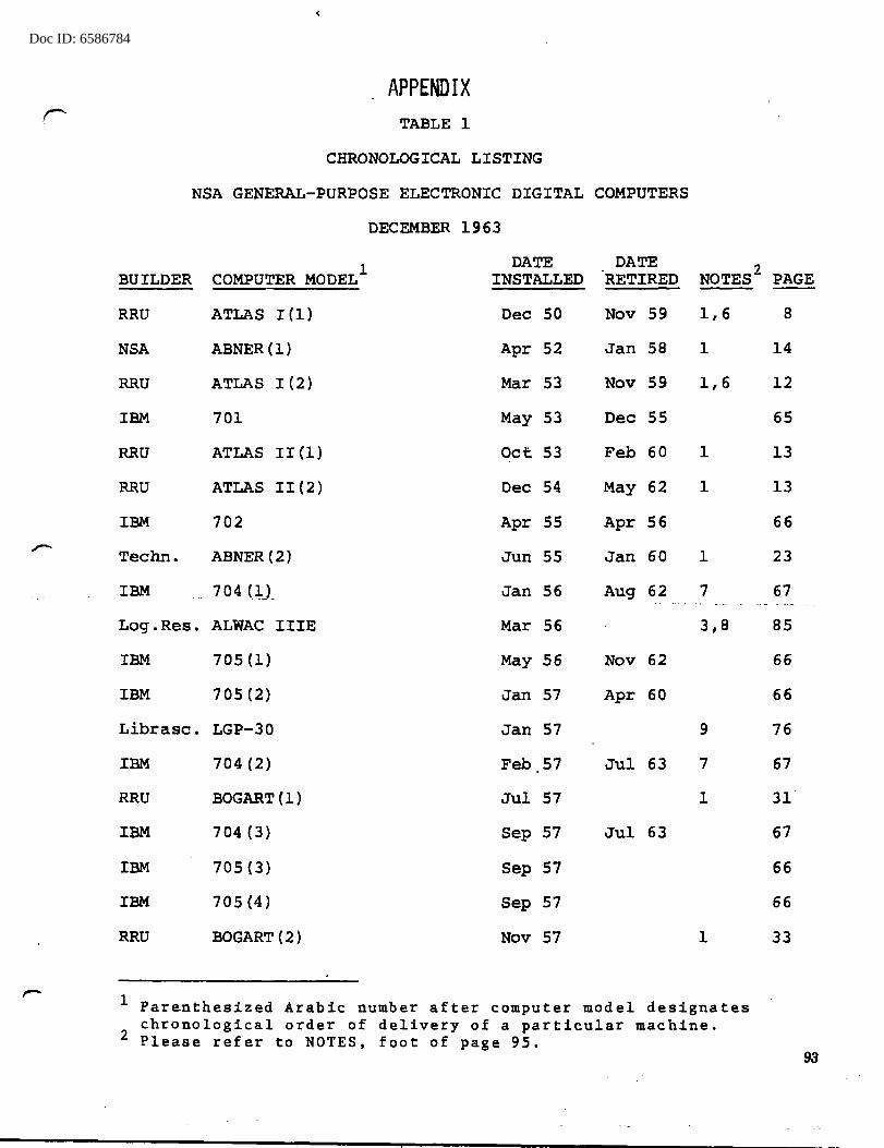
Doc ID: 6586784
r APPENDIX
TABLE 1
CHRONOLOGICAL LISTING
NSA GENERAL-PURPOSE ELECTRONIC DIGITAL COMPUTERS
DECEMBER 1963
COMPUTER MODEL1 DATE DATE
NOTES2
BUILDER INSTALLED RETIRED
RRU ATLAS I (1) Dec 50 Nov 59 1,6
NSA ABNER(l) Apr 52 Jan 58 1
RRU ATLAS I (2) Mar 53 Nov 59 1,6
IBM 701 May 53 Dec 55
RRU ATLAS II(l) Oct 53 Feb 60 1
RRU ATLAS II(2) Dec 54 May 62 1
IBM 702 Apr 55 Apr 56
Techn. ABNER (2.) Jun 55 Jan 60 1
IBM 7 _Q 4 (_],.) _ Jan 56 Aug 62 7
Log.Res. ALWAC IIIE Mar 56 3,8
IBM 705(1) May 56 Nov 62
IBM 7 05 (2) Jan 57 Apr 60
Librasc. LGP-30 Jan 57 9
IBM 704(2) Feb 57 Jul 63 7
RRU BOGART(l) Jul 57 1
IBM 704 (3) Sep 57 Jul 63
IBM 705(3) Sep 57
IBM 705 (4) Sep 57
RRU BOGART(2) Nov 57 1
1 Parenthesized Arabic number after computer model designates chronological order of delivery of a particular machine.
2 Please refer to NOTES, foot of page 95.
PAGE
8
14
12
65
13
13
66
23
67
85
66
66
76
67
31
67
66
66
33
93
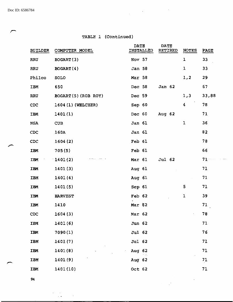
Doc ID: 6586784
TABLE 1 (Continued)
DATE DATE BUILDER COMPUTER MODEL INSTALLED RETIRED NOTES PAGE
RRU BOGART(3) Nov 57 1 33
RRU BOGART(4) Jan 58 1 33
Philco SOLO Mar 58 1,2 29
IBM 650 Dec 58 Jan 62 67
RRU BOGART ( 5) (ROB ROY) Dec 59 1,3 33,88
CDC 1604 (1) (WELCHER) Sep 60 4 78
IBM 1401(1) Dec 60 Aug 62 71
NSA CUB Jan 61 1 36
CDC 160A Jan 61 82
CDC 1604 (2) Feb 61 78
IBM 705(5) Feb 61 66
IBM .. 1401 (2) ------- - --· - Mar 61 Jul 62 71· -
IBM 1401(3) Aug 61 71
IBM 1401(4) Aug 61 71
IBM 1401(5) Sep 61 5 71
IBM HARVEST Feb 62 1 39
IBM 1410 Mar 62 71
CDC 1604(3) Mar 62 78
IBM 1401(6) Jun 62 71
IBM 7090(1) Jul 62 76
IBM 1401(7) Jul 62 71
IBM 1401(8) Aug 62 71
IBM 1401 (9) Aug 62 71 ,,,.-..
IBM 1401(10) Oct 62 71
94

Doc ID: 6586784
r TABLE 1 {Continued)
DATE DATE BUILDER COMPUTER MODEL INSTALLED RETIRED NOTES
IBM 1401(11) Nov 62 ·--
IBM 7090(2) Jan 63
CDC 1604(4) (PULLMAN) Jan 63 4
IBM 1401 (12) Feb 63
RRU UNIVAC 1224A (1) (CRISP I) Jun 63 1,4
RRU UNIVAC 1224A(2) (CRISP!) Jul 63 1,4
CDC 1604A(5) Jul 63
RRU UNIVAC 490(1) (RYE) Aug 63 3
IBM 7090 (3) Nov 63
IBM 1401(13) Nov 63
Builder Abbreviations:
RRU NSA IBM Techn. Log.Res. Librasc.
Remington-Rand-Univac, Div. of Sperry-Rand, Inc. National Security Agency & predecessor agencies International Business Machines Corporation Technitrol, Inc.
Philco CDC
NOTES:
Logistics Research, Inc. Librascope (now Commercial Computer Div., General Precision, Inc.) Philco Corporation, subsidiary o·f Ford Motor Co. Control Data Corporation
1. Agency-developed or sponsored computer design 2. Operational use discontinued Aug 63; now used for training 3. Agency-sponsored remote-operational use 4. Used with Agency-sponsored special attachment 5. Used for communications security purposes 6. Additional memory (4096 words) installed in 1956 7. IBM 704(1) and 704(2) memory capacity increased to
32,768 words in Jan 62 and March 62 respectively 8. Remote-station use discontinued Sep 59 9. Replacement new LGP-30 installed July 58 at no cost
PAGE
71
76
82
71
36
39
82
89
76
71
95
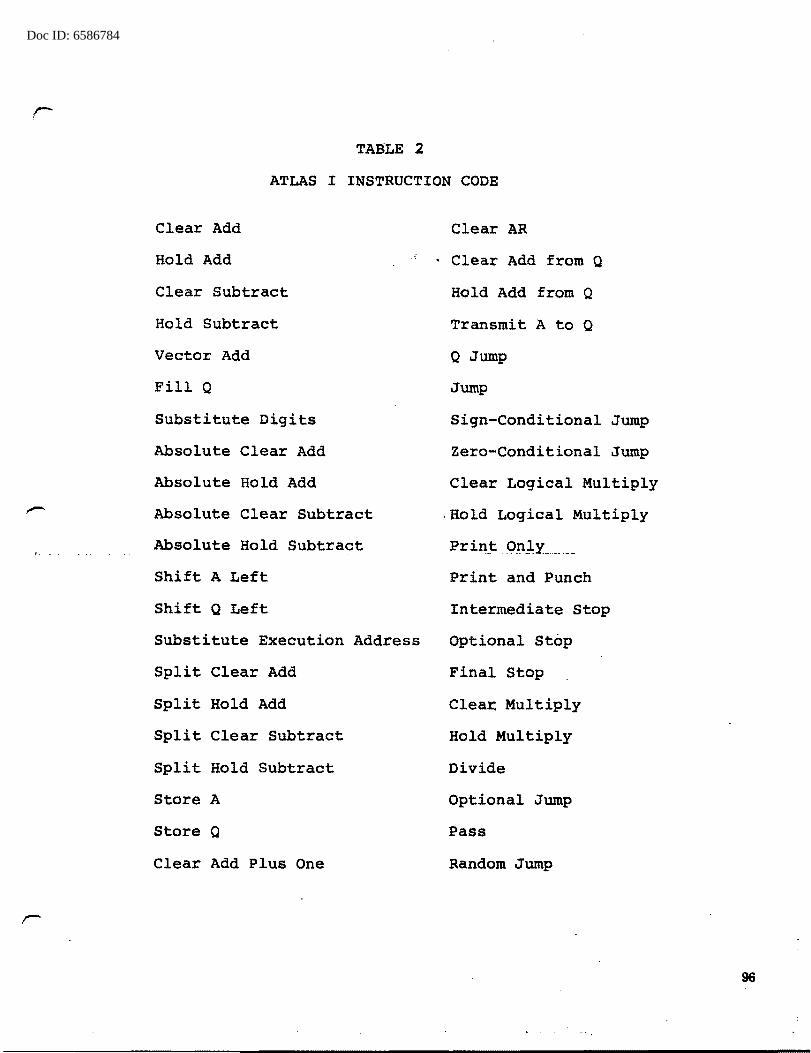
Doc ID: 6586784
.r-
TAJ:lLE 2
ATLAS I INSTRUCTION CODE
Clear Add
Hold Add
Clear Subtract
Hold Subtract
Vector Add
Fill Q
Substitute Digits
Absolute Clear Add
Absolute Hold Add
Absolute Clear Subtract
Absolute Hold Subtract
Shift A Left
Shift Q Left
Substitute Execution Address
Split Clear Add
Split Hold Add
Split Clear Subtract
Split Hold Subtract
Store A
Store Q
Clear Add Plus One
Clear AR
Clear Add from Q
Hold Add from Q
Transmit A to Q
a Jump
Jump
Sign-Conditional Jump
Zero-Conditional Jump
Clear Logical Multiply
.Hold Logical Multiply
Print .O_n],y _____ _
Print and Punch
Intermediate Stop
Optional_ Stop
Final Stop
Clear. Multiply
Hold Multiply
Divide
Optional Jump
Pass
Random Jump
96
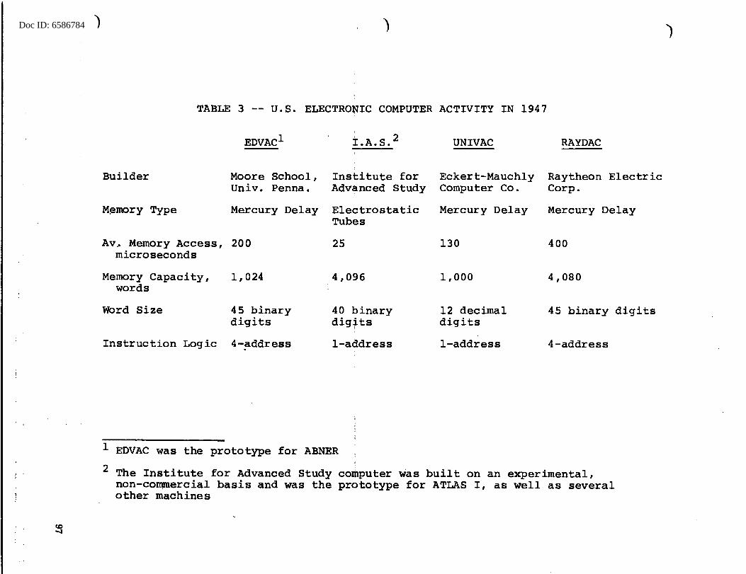
Doc ID: 6586784 ) )
TABLE 3 -- U.S. ELECTRO~IC COMPUTER ACTIVITY IN 1947
Builder
M~mory Type
EDVAC1
Moore School, Univ. Penna.
Mercury Delay
Av~ Memory Access, 200 microseconds
Memory Capacity, 1,024 words
Word Size 45 binary digits
Instruction Logic 4-address
: 2 I.A.S.
Institute for Advanced Study
Electrostatic Tubes
25
4,096
40 binary digits
I
!-address
1 EDVAC was the prototype for ABNER
UNIVAC
Eckert-Mauchly Computer Co.
Mercury Delay
130
1,000
12 decimal digits
!-address
RAYDAC
Raytheon Electric Corp.
Mercury Delay
400
4,080
45 binary digits
4-address
2 The Institute for Advanced Study computer was built on an experimental, non-commercial basis and was the prototype for ATLAS I, as well as several other machines
)

Doc ID: 6586784
TABLE 4
ABNER INSTRUCTION CODE
STOP
PROVISIONAL STOP
HALT
AUX ORDER
TAPE (BLOCK)
TAPE (WORD)
PRINT UPPER
PRINT LOWER
COMPARISON
COMPARISON COUNT
FULL MULTIPLICATION
EXPAND TRANSFER
RANDOM JUMP
SKIP
FULL DIVISION
SUBTRACTION
SWISH
SELECTIVE REPLACEMENT
PATTERN COUNT
SHIFT AND REPLACE
PENTABIT TRANSFER
EQUALITY
EQUALITY COUNT
LOW ORDER MULTIPLICATION
MOD WITHIN WORDS
SHORT MULTIPLICATION
PENTABIT MOD
DIVISION
CYCLIC TRANSFER
ADDITION
DECABIT MOD
98

Doc ID: 6586784
Adams Associates, Inc.
Brummett, Walter H., Jr., Atomic Energy Commission
Campaigne, H.H.
Control Data Corporation
Control Data Corporation
Engineering Research Assoc.
House of Representatives, Committee on Post Off ice and Civil Service
House of Representatives, Committee on Post Office and Civil Service
IBM Data Systems Division
IBM Data Systems Division
D4-Nov-76-SJ-24926
REFERENCES
Computer Characteristics Nov 63 Quarterly
Report of Conferences in 17 Nov 55 Washington, D.C., Regarding Proposed Purchase of Computing Machine for LASL
Report on Conference at 15 May 46 Navy Dept. (Survey of large-scale automatic computing machines, by J. vonNeumann)
IDA/CRD 77 Order for 1604 (Preliminary Engineering Draft, undated)
CDC 160A Computer
Proposal for a Magnetic Core Memory for ATLAS I, .(l)._ & (2)
Use of Electronic Data Processing Equipment in the Federal Government
Jul 63
19 Nov 54
16 Oct 63
Inventory of Automatic Data 25 Oct 63 Processing Equipment in the Federal Government
Final Report, IBM 7950 Data 1 Sept 62 Processing System
Final Report, Development 30 Nov 63 of an Automatic Proqramminq System
99