history of autostereoscopic cinema - hologlyphics · history of autostereoscopic cinema walter...
TRANSCRIPT
Stereoscopic Displays and Applications XXIII, edited by Andrew J. Woods, Nicolas S. Holliman, Gregg E. Favalora, Proc. of SPIE-IS&T Electronic Imaging, SPIE Vol. 8288, 82880R
© 2012 SPIE-IS&T · CCC code: 0277-786X/12/$18 · doi: 10.1117/12.909410
SPIE-IS&T/ Vol. 8288 82880R-1
History of autostereoscopic cinema
Walter Funk*, Hologlyphics
San Francisco, CA, USA
ABSTRACT
This paper covers the history of autostereoscopic cinema, from the beginnings of autostereoscopy in the 1800s, the
development of motion capability and it's subsequent evolution to present techniques. Public viewings of
autostereoscopic movies have occurred on a semi-ongoing basis since the early 1940s. In Moscow and other cities,
theaters were constructed called stereokinos, for showing autostereoscopic films, with specially positioned seating for
proper viewing. The Cyclostéréoscope was an autostereoscopic cinema system invented by François Savoye in France. It
was based around a drum made of metal bars that revolve around a screen. For several years in the 1940s and 1950s, it
was open to the public in Paris. Any film made in a dual film format could be shown. Besides dedicated theaters in
Russia and France, exhibits of content have occurred outside devoted theaters. The paper focuses on the history of
autostereoscopic technology developed for entertainment, public viewing of content, the individuals involved and the
content itself.
Keywords: Autostereoscopic, cinema, 3D, movies, stereoscopic, holographic movies, stereokino
1.INTRODUCTION
Much of the early work done in autostereoscopic cinema evolved from parallax barrier techniques that began in
autostereoscopic photography. Sometimes called the grid or grill method, a glass plate with alternating vertical opaque
and transparent lines was placed a short distance in front of an interlaced photograph. The opaque lines of the grill,
known as bars, would block light passing though the grill and the transparent lines would allow light to pass. Behind the
grill was a composite picture in which left and right images were broken up into small vertical bands, the image bands
for one eye being alternately interlaced between the image bands for the other. The grill was usually made on a high
contrast photographic plate. When the grill was spaced at the prescribed distance in front of the composite and viewed
from the correct distance, the observer was able to see a binocular view. Under these conditions, the left eye will see
only the alternating strips comprising the left image, with the right strips being hidden by the grill's opaque lines. In the
same manner, the right eye will see only the alternating strips comprising the right image, with the left strips being
hidden by the opaque lines. The grill or grid was sometimes called a lined network or line screen, terms that stem from
its use in early color photography and half-tone printing. Later, larger grid screens, sometimes made of wire or metal
bars, were used for projecting moving images onto screens behind them. The larger screens for cinema were sometimes
called rasters, selector grills, or in the case of a grill developed for cinema, a radial raster.
The grid technique for autostereoscopic photography was commonly known as a Parallax Stereogram, as popularized by
Ives. A well-known variation is the Parallax Panoramagram as invented by Kanolt, which allowed more than one
stereoscopic perspective to be viewed. Instead of two alternating bands of left/right images, the alternating bands
comprised a panorama of perspectives. This adds to the image horizontal parallax and to a small degree reduced
pseudoscopic viewing issues associated with the Parallax Stereogram, which had been one of its major limitations.
These photographic grid techniques were widely adapted to cinematic projection. Other techniques used early on for
autostereoscopic cinema include grooved corrugated screens, lenticular screens, integral methods, and mirror methods.
Adapting these techniques to cinema was difficult, not only because of the need to apply projection and motion, but also
because the grid technique was far from perfect. The Parallax Panoramagram solved some of the issues associated with
Parallax Stereograms, which would apply when adapted to moving pictures, but the filming of multiview scenes is
highly complex.
SPIE-IS&T/ Vol. 8288 82880R-2
Besides motion, there are several other drawbacks associated with adapting the Parallax Stereogram method to the
cinema. The method is limited in that there is only one correct viewing distance, and sideways motion of the head
reverses the views, producing pseudoscopic images. In addition, due to absorption at the grid's bars, at least 50% of
available light is lost. The grid also causes reduced horizontal resolution of the scene. Finally, the effects of diffraction at
the edges of the bars create a grid pattern superimposed on the image. These limitations were well known in the early
days, in fact most improvements done by inventors working on line screen systems were not new techniques of
autostereoscopy, but corrections of these well known limitations. All these problems of autostereoscopic photography
were involved in the challenge of making the leap to cinema, along with the problems of projection, adding motion,
showing to a large audience, and difficulty with autostereoscopic capture, especially multiview. In addition, theaters
being physically fixed structures, the alteration/re-design of theater floors, screens, and projection areas, is a large
undertaking.
Inventors originally worked with systems using parallel lined networks to perform stereo projections but it is not
possible to use these systems in cinemas where a screen is observed at a distance ranging from 10 to 30 meters.
Solutions to these obstacles came in the form of theaters with sloped floors, 'radial rasters', moving rasters, lenticular
screens, integral techniques and more.
2.AUTOSTEREOSCOPIC PHOTOGRAPHY
An early attempt at free viewing of stereoscopic images was made by French photographer Antoiné Claudet after
noticing depth in the ground glass of a camera obscura when objects are placed on the opposite side. He first conveyed
these ideas in a paper “On the Phenomenon of Relief in the Image formed on the Ground Glass of the Camera Obscura”,
communicated to the Royal Society of London on May 8, 18561. To view objects this way, one had to “look on the
ground glass perfectly in the middle, the two eyes being equally distant from the center”, if the observer moved more
than 6°, the effect was lost. Claudet wondered if a stereoscope placed on the other side of the ground glass, at the
distance of the focus of the stereoscope's semi-lenses, would also produce a sense of depth.
In 1858 he build a device, described in a Paper to the Royal Society of London, called the Stereomonoscope2, described
as “nothing more than an ordinary camera obscura supplied with two lenses”. Both lenses were mounted side by side on
a dual sliding frame, with pictures mounted behind them, acting as a stereoscope. Sliding the lenses allowed the
horizontal separation necessary, according to their focal distance, for producing on the ground glass the coalescence of
the images of the two slides. The pictures were mounted on the other horizontally sliding frame, allowing them to be
sufficiently apart to be refracted on the ground glass of the camera obscura by the two lenses. In Claudet's own words,
the separate views are directed to each eye because, “the right picture of the slide, being obliquely refracted on the
ground glass by the right lens in a line coinciding with the axis of the left eye, is visible only to that eye; and the left
picture, being refracted obliquely by the left lens in an opposite direction coinciding with the right eye, is only visible to
that eye.” Finally, he ended his account to the Royal Society by describing it as imperfect and susceptible to
improvement. Surely, viewing it must have been highly awkward, as one needed to remain within 6° of the lens’s center.
Work on the Stereomonoscope did not continue much beyond this.
The first successful autostereoscopic viewing device was Swan's Cube3, 4
, more commonly known as the Crystal Cube
Miniature or Casket Portrait. It provided two very large viewing zones separated by a fairly large boundary. The pictures
are viewed as hand colored transparencies printed from negatives on small mica plates affixed to two prisms, which are
placed together to form a cube. The two prisms are of slightly different angles producing a very small diagonal air gap
that slightly increases through the middle of the cube. The transparencies need to be lit from behind. Viewing from
above in (Fig. 1a), two photographs (h and h') taken from left and right perspectives respectively, are mounted on two
prisms (i j k) and (i l k) with photograph h' reversed. The two eyes (x and y), typically a little less to the side than shown,
will each receive a separate image. The rays of light from photograph h' will pass laterally inwards until they hit the
polished surface at the point Z, reflected at an angle equal to their incidence, not meeting the surface (i j) of the upper
prism vertically they will be refracted upon entering the air, and will pass on to the eye y. The image from photograph h'
will be inverted upon reflection, therefore the image at eye y will not be reversed. The polished surface is partly

SPIE-IS&T/ Vol. 8288 82880R-3
transmissive, partly reflective. The rays of light from the other photograph h, can be transmitted towards eye x without
reflection or refraction. The image h' which is reflected is inverted to compensate for reversion which takes place when
reflection occurs. Not shown in the figure is the optional curved prism surface on the front of the viewing side, which
can magnify the image and increase the viewing range.
Figure 1. a) Ray diagram of Henry Swan's Crystal Cube. b) James Clerk-Maxwell's cyclide figures made for the real-image
stereoscope.
Beginning in 1862 Henry Swan's Casket Portrait Company in London produced 'Crystal Cube Miniatures' or 'Casket
Portraits' in multiple forms, such as elaborate hinged cases or casket-like boxes. Most of the Crystal Cubes were custom
portraits, such as a very life like portrait of the British Statesman Lord Brougham. Another portrait of Sarah Anne
Bennett taken around 1865, is made of hand-colored transparencies on talc, affixed to the prisms inside a silk lined
wooden case covered in leather. He also reached out to other photographers with articles, such as one with tips on
printing, coloring and mounting the transparencies5. In 1864 the Photographic Society of Scotland held an exhibit in
Edinburgh where a Crystal Cube featuring a statue of Robin Hood made by sculptor Miss Susan Durant, and the Lord
Brougham portrait, both done with the collodion process, were shown. A year later, at the Dublin International Exhibit,
six of his miniatures were on display. Swan's Crystal Cubes were on display at the 32nd
meeting of the British Medical
Association, held in Cambridge August 3-5, 1864, in the first night's after-meeting entertainment “the conversaziones”.
The Dictionary of Photography had an entry for Crystal Cube until around 1902 and even up until 1912, Cassell's
Cyclopaedia of Photography listed an entry.
Scottish physicist and mathematician James Clerk-Maxwell, credited for formulating classical electromagnetic theory,
devised a 'real-image stereoscope' for the viewing of mathematical figures. A frame supporting two pictures, a
stereoscopic pair inverted, is placed one foot behind two side-by-side convex lenses with ½ ft. focal length. The distance
between the lens's centers is 1¼” horizontally. One foot in front of the convex lenses is placed a 3” diameter convex lens
with 2/3 ft. focal length. The observer stands about 2 ft. in front of the large lens. Rays of light from the images pass
through the center of the two small lenses, passing through the 3” lens that forms an inverted real-image, appearing to be
the same distance as the large lens. As the observer fixes their eyes on the frame of the large lens, they see both views
combined into one.
Maxwell's mention of the real-image stereoscope was in the 1868 paper "On the cyclide"6, in a footnote. The cyclide
(Fig. 1b) is a family of algebraic surfaces of which he produced stereoscopic figures to be viewed in his real-image
stereoscope. The real-image stereoscope is a similar arrangement to the Stereomonoscope, the viewer needing to place
their eyes at a specific point in space, in contrast to the wider viewing zones of the Crystal Cube Miniature.
The parallax barrier technique of autostereoscopic viewing was first suggested in France by Auguste Berthier, at the end
of a two part article called "Images stéréoscopiques de grand format”7 in the French magazine Cosmos on May 23, 1896.
The article was an overview of stereoscopic methods, within the article he suggested this method of viewing. He began

SPIE-IS&T/ Vol. 8288 82880R-4
by stating that the technique was far from elegant and in need of improvement, it was for that reason he outlined it.
Berthier included in his article an optical diagram tracing the paths of light rays from an observers eyes to an interlaced
photographic image of a stereoview split into two alternating vertical bands, viewed through a screen of alternating
opaque and transparent elements. (Fig. 2b)
Also included was a stereoscopic photograph of a house, (Fig. 2a) alternately interlaced into parallel sliced vertical
bands, or as he calls it juxtaposed. He states the dimensions of the bands were “greatly exaggerated” for illustrative
purposes, and continues to describe their need to be much smaller, describing a glass 'network' used in the color
reproduction process of John Jolly. A typical screen of this type would have 200 lines per inch. By placing the glass
network in front of the sliced bands of the two photographs, parts of the images are 'masked', others are viewable. A
sizable description and analysis was given on the light rays of each alternating band traveling into the separate eyes.
Finally Berthier mentioned difficulty regarding the limitations of viewing angles at varying distances and also
orientation of the lines on the screen in relation to the eye, suggesting that the size and shape of the lines could be
modified, or that another possible solution existed for these disadvantages.
Figure 2. a) Berthier's stereoscopic picture 'juxtaposed' into two alternating bands. b) Ray diagram showing the two eyes and their
line of sight between the grid's lines.
In two 1899 US patents by John Jacobson of Boston, Massachusetts, both filed on the same day, a parallax barrier
process is vaguely described. His brief patent titled 'Pictorial Reproduction'8, mentions the use of alternate vertical strips,
preferably of fine lines, of images taken from left and right points of view. Specific information on how to view
stereoscopic images was not given, only that it's possible. Also mentioned is the possibility of projecting such an image
onto a screen. In the other patent titled 'Stereograph'9, a photographic print comprising alternate interlaced vertical strips
of equal width, of left and right points of view, is mounted on the back of a transparent plate. The plate is corrugated or
grooved on the side opposite to the mounted print. When viewed in front of the plate, through the corrugations, both
images on the strips combine into a “complete unbroken picture” seen in relief. Both patents lack any detailed
information on construction specifics or how both views were separately directed to the left and right eyes.
In 1902 Frederik E. Ives developed a parallax barrier photography technique he called a Parallax Stereogram10
. He was
also well known for inventing novel approaches to color photography, early anaglyph movies with Jacob Leventhal, and
the half-tone process that made the publication of photographs in newspapers and magazines possible. Ives said he didn't
SPIE-IS&T/ Vol. 8288 82880R-5
know about Berthier's article in Cosmos, but independently came across the idea as an outgrowth of his half-tone and
color photography work. These Parallax Stereograms were well received in their time and many other inventors went on
to adapt and improve this system, including Ives himself11
.
Ives devised a method for capture on a single plate through simple alteration of his “Kromolinoskop” camera. He placed
a line screen inside a camera in front of the sensitive plate at a close distance, and formed an image with a 3-½ inch lens
in front of two apertures spaced about 2 ½ inches apart. When the image is photographed through the screen it is divided
into small elements, comprised of alternating vertical bands. If such a photograph is viewed through a similar screen, at
approximately the same distance as the focal length of the lens, a stereoscopic image is seen. This is also one of the
limitations of a Parallax Stereogram, to view it one has to be a specific distance from the line screen.
Ives definitely inspired many people to look forward with the introduction of his Parallax Stereogram. He even inspired
some to look back on a long forgotten time, as told in the October 1902 issue of The Photo-Miniature. "This adds one to
the list of stereoscopic curiosities by which a stereoscopic effect can be realized without the use of any special
instrument by the beholder, and in this respect it ranks near to the Clerk-Maxwell system of real-image stereoscopy as
used by him in the class-teaching of solid geometry. In the same class we have the crystal cube of Mr. Henry Swan, and
the Claudet stereo-monoscope, which was exhibited at the Polytechnic Institute some forty years ago. The introduction
of Mr. Ives' parallax stereogram may possibly revive the popularity of open-vision stereoscopic effects.“
Although Ives was mainly known as an inventor, from the beginning he understood the potential for new artistic
exploration. In his first paper on the Parallax Stereogram12
he envisioned “...a magical gallery of sculpture, the statues
appearing to be of life-size, and as if seen through and beyond a glass behind which there was in reality nothing but
empty space.”
One of the individuals who continued the work of Berthier and Ives was Eugéne Estanave in France. He worked for
physicist Gabriel Lippmann, who Estanave considered his mentor. Beginning working with line screens in 1904, he later
developed the Autostereoscopic Plate in 1908, which had the photographic plate and line screen on the same glass plate.
In 1906 he explored the use of a line screen in projecting images13
, a definite step towards cinematography. (Fig. 3a)
Two left/right lantern images were rear projected with two objectives through a line screen onto a translucent screen. It
was viewed from the opposite side thorough another line screen placed in front of the translucent screen. He also used
the line screen technique with X-ray photography and to create ‘changing’ images14
.
In 1908, Professor Gabriel Lippmann in France outlined the method of integral photography15
, which captures images
using a special photographic plate consisting of a large number of very small lenses. Each lens would form a
microscopic image on the light sensitive layer behind the lenses, every image differed in both horizontal and vertical
parallax. The number of microscopic images formed on the light sensitive layer is equal to the number of lenses. The
lenses are also called 'fly's eye' lenses. They each act as an individual lens, so the objects are captured without a camera,
with the object placed directly in front of the plate. After the plate is developed, and properly copied onto another
Lippmann plate, it can be illuminated from the emulsion side and viewed from the lens side. When the picture is viewed
though the 'fly's eye' lens, a spatial image is formed which has horizontal and vertical parallax. Lippmann, who also won
the Nobel Prize in 1908 for color photography based on the interference phenomenon, did not actually produce an
integral photograph at the time. The manufacture of such a lens was not possible until many years later.
In 1911 Professor P. P. Sokolov of Moscow State University produced detailed mathematical and experimental proof of
Lippmann's Integral Photography. Sokolov produced a relatively dark spatial image of a light-bulb filament, using a pin
hole sheet with conical apertures16
. He also earlier in 1908 produced a method of autostereoscopic viewing by reflected
light, as opposed to the common use of light transmission. This was based on a corrugated light sensitive surface, the
shape of the corrugations if viewed from above were teeth-like triangles zig-zaging horizontally. (Fig. 3b) The triangular
shape of the teeth is flat on one side and sloped on the other. This corrugated surface is exposed with light rays
emanating from two directions, each 7 cm apart, representing the left and right views. The right hand side of the teeth
captured the right view and the left hand side of the teeth captured the left view. If the teeth were sufficiently small
enough, they would upon viewing direct the views to each eye separately.
SPIE-IS&T/ Vol. 8288 82880R-6
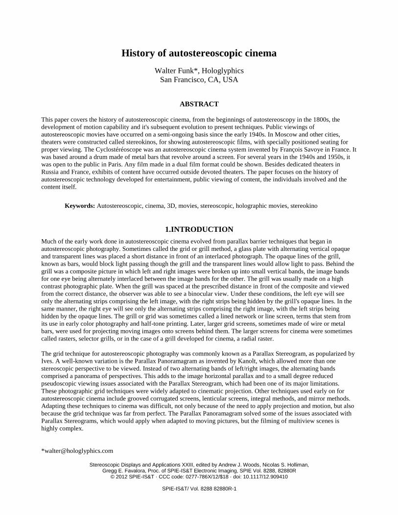
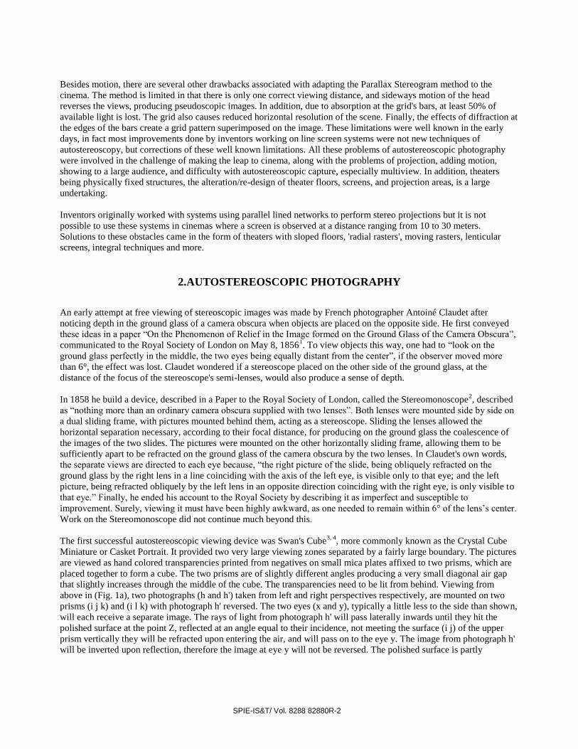
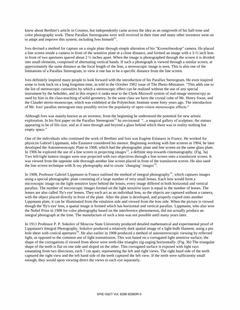
Figure 3. a ) Estanave's projection ray diagram. Left/right lantern images rear project through line screen onto translucent screen,
viewed from opposite side through another line screen. b ) Sokolov's ray diagram of grooved teeth technique.
Swiss ophthalmologist Walter Hess was the first to replace Lippmann's semi-spherical lenses, the ‘fly's eye’, with
parallel vertical semi-cylindrical lenses17, 18
. Hess first described this lenticular lens in his 1912 British Patent No.
13,034. This lenticular lens loses the vertical parallax information captured with true integral photography, but greatly
reduces manufacturing complexity of the lens array. The use of a lenticular sheet besides simplifying the integral process
also improved limitations with line screens such as the loss of light associated with an opaque grill. Many continually
improved the lenticular work of Hess, but the basic foundation for lenticular imaging he laid out is still the same today.
In 1915 Clarence W. Kanolt proposed the first method that allowed for multiple views behind the barrier screen19
.
Kanolt used various 'scanning' type cameras that moved horizontally in front of a subject, or in a horizontal arc around
them. This autostereoscopic technique is known as a Parallax Panoramagram.
Louis Lumiére in 1920 produced spatial photographs with his Photo-stéréo-synthése technique20, 21
. Multiple images of
an object at varying depths of focus divide the object into successive frontal planes called ‘slices’. The 'slices' are then
'stacked' to recreate a spatial image. This is known as 'slice stacking'. Each slice represents one frontal plane of the
subject. When re-assembled by placing 'slices' printed on transparent glass plates back in their relative position, the
spatial image is rebuilt in space.
3.AUTOSTEREOSCOPIC CINEMA: THE EARLY DAYS
David Kakabadze was a Georgian Modernist Artist, a painter, sculptor, photographer, stage designer and
cinematographer, who in 1919 traveled to Paris. Along with other young artists, he was sent with a grant from the
independent Georgian government to live and study art. Early on in Paris, he continued artistic experimentation with
Cubism, which began in Petersburg. He was inspired by the cubist task of simultaneous fixation of visible reality from
different points. Interested in film, Kakabadze became dissatisfied that movies were not perceived in three dimensions.
He wrote about dynamic images and spaces in art, which should replace static images in a static space and also of new
potentials of dynamic eurhythmics.
He began work not only on spectacles-free stereoscopic cinema but the creation of new three-dimensional moving
images in art. Nikolai Valyus in his book “Stereoscopy” described one such system where the screen was a special
corrugated metal screen with separate cut grooves, reflecting the left and right views to the proper eyes. Images would
need to be projected from the proper angle, in a manner similar to the Sokolov method. In 1922 he applied for a patent,
“Stéréo-cinématographe donnant la vision du relief naturel”22
, outlining the projection of left/right views captured on a
single film, onto a special screen. The screen was comprised of two sheets of glass or other transparent material. The
first glass sheet had a roughened surface of a specific shape and a tilt of the screen was specified. The second glass sheet
needed to be transparent. His 1923 patent “Stéréocinématographe”23
outlined a variation. Spectators could view the

SPIE-IS&T/ Vol. 8288 82880R-7
screen from the front, observing the images by reflected light, or view the screen from behind to view the images by
transmitted light. If viewing by reflected light, the screen must be perfectly smooth, such as a polished metal or an
enameled surface. For viewing by transmitted light, the screen must be made of translucent material, such as glass,
canvas or paper coated with a fatty body. In the typical case of viewing by reflected light, the images are projected onto
the screen of a grooved surface at an angle greater than ordinary stereoscopic projection, so that the line of reflection for
both views is correctly aligned with each eye separately.
He expanded on this work in a 1924 British patent24
and 1925 Swiss patent “Installation stéréocinématographique”25
where he describes a projection method with one embodiment using a two-prism arraignment through which images are
projected onto a screen. The prisms were typically placed in a cubic block, one had vertical silvered bands forming
vertical alternating bands of reflective surfaces with empty spaces in between, images that would meet the silver bands
would be reflected and the ones that fall between the silver bands would be transmitted. The transmitted and reflected
bands of light were directed towards two separate mirrors that would reflect both paths of light onto the screen at the
proper angle. When left and right are projected onto the screen at the correct separate angles, “each eye of the viewer
selects the image of its own, and gives the sensation of stereoscopic relief.” Alternating shutters in synch with the
projector were placed between the prisms and mirrors alternately blocking light or allowing it to pass. Other projection
embodiments use alternating prisms or mirrors to project both views onto the screen at the separate correct angles, and
also the use of folded systems for simultaneous projection without alternating shutters.
Figure 4. Kakabadze's spectacles-free stereoscopic cinema device. (Photograph courtesy Georgian Museum of Photography)
A prototype device (Fig. 4) has been constructed. To produce Kakabadze's spectacles-free stereoscopic cinema device, a
joint trust company was formed. Unfortunately due to insufficient funding, this work was unable to continue. Kakabadze
continued to explore the artistic use of space in his collages made of decorated metal or wood frames, featuring collage
elements such as flickering electric bulbs, lenses, mirrors, metallic parts and glass. Reflections in the mirrors added
depth to the collages and along with the flickering electric bulbs, impart a dynamic element to the composition. Spatial
work continued from 1924-1925 on biomorphic abstractions of organic curvilinear forms with colors adding a sense of
depth on a plane. His later sculptures continued to use elements such as metal, wood and lenses thus evolving the forms
from a plane into space, a logical development. In 1926 Kakabadze's sculpture work was purchased for the Société
Anonyme collection by Kathrine Drier and exhibited the same year at The Brooklyn International Exhibit. In 1950 he
proposed a method for producing 'analogue holograms' demonstrating this idea by segmenting a photograph of Stalin's
head into 19 'slices'. Kakabadze never built the device but recently artist Lunds Konsthall constructed a prototype in
collaboration with art historian Ketevan Kintsurashvili.
Beginning in the late 1920s, Professor Edmond Noaillon of Belgium published several patents
26, 27, authored articles on
autostereoscopic theatre design28
and inspired renown filmmaker/artist Jean Painlevé to seek, along with engineer André
SPIE-IS&T/ Vol. 8288 82880R-8
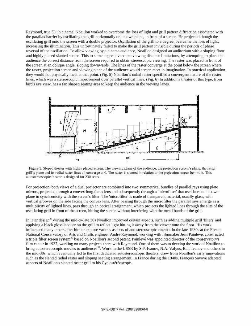
Raymond, true 3D in cinema. Noaillon worked to overcome the loss of light and grill pattern diffraction associated with
the parallax barrier by oscillating the grill horizontally on its own plane, in front of a screen. He projected though the
oscillating grill onto the screen with a double projector. Oscillation of the grill to a degree, overcame the loss of light,
increasing the illumination. This unfortunately failed to make the grill pattern invisible during the periods of phase
reversal of the oscillation. To allow viewing by a cinema audience, Noaillon designed an auditorium with a sloping floor
and highly placed slanted screen. This to some degree overcame viewing distance limitations, by attempting to place the
audience the correct distance from the screen required to obtain stereoscopic viewing. The raster was placed in front of
the screen at an oblique angle, sloping downwards. The lines of the raster converge at the point below the screen where
the raster, projection screen and viewing plane of the audience would screen meet in imagination. In practical application
they would not physically meet at that point. (Fig. 5) Noaillon’s radial raster specified a convergent nature of the raster
lines, which was a stereoscopic improvement over parallel vertical lines. (Fig. 6) In addition a theater of this type, from
bird's eye view, has a fan shaped seating area to keep the audience in the viewing lanes.
Figure 5. Sloped theater with highly placed screen. The viewing plane of the audience, the projection screen’s plane, the raster
grill’s plane and its radial raster lines all converge at 0. The raster is slanted in relation to the projection screen behind it. This
autostereoscopic theater is designed for 230 seats.
For projection, both views of a dual projector are combined into two symmetrical bundles of parallel rays using plate
mirrors, projected through a convex long focus lens and subsequently through a 'microfilter' that oscillates on its own
plane in synchronicity with the screen's filter. The 'microfilter' is made of transparent material, usually glass, with
vertical grooves on the side facing the convex lens. After passing through the microfilter the parallel rays emerge as a
multiplicity of lighted lines, pass through an optical arraignment, which projects the lighted lines through the slits of the
oscillating grill in front of the screen, hitting the screen without interfering with the metal bands of the grill.
In later design29
during the mid-to-late 30s Noaillon improved certain aspects, such as adding multiple grill 'filters' and
applying a black gloss lacquer on the grill to reflect light hitting it away from the viewer onto the floor. His work
influenced many others after him to explore various aspects of autostereoscopic cinema. In the late 1930s at the French
National Conservatory of Arts and Crafts engineer André Raymond, working with filmmaker Jean Painlevé, constructed
a triple filter screen system30
based on Noaillon's second patent. Painlevé was appointed director of the conservatory's
film center in 1937, working on many projects there with Raymond. One of them was to develop the work of Noaillon to
bring autostereoscopic movies to audiences31
. Work in the USSR by S.P. Ivanov, N.A. Valyus, B.T. Ivanov and others in
the mid-30s, which eventually led to the first dedicated autostereoscopic theaters, drew from Noaillon's early innovations
such as the slanted radial raster and sloping seating arrangement. In France during the 1940s, François Savoye adapted
aspects of Noaillon's slanted raster grill to his Cyclostéréoscope.

SPIE-IS&T/ Vol. 8288 82880R-9
Figure 6. Convergent lines of the grill pattern, known as a radial raster. These lines converge at the meeting point of the
projection screen’s plane behind the raster and viewing plane of the audience.
Herbert E. Ives was a well-respected physicist who was well known for his pioneering work in early television at Bell
Labs. He was also the son of Frederik E. Ives, inventor of the Parallax Stereogram. Herbert greatly extended the
Parallax Panoramagram work of Kanolt, adapting the technique to motion pictures. The method of a horizontally
swinging camera as with Kanolt's technique is of course not applicable to motion pictures. One of H. E. Ives' earlier
proposed solutions to this obstacle was an array of 14-15 high-speed cameras in an arc32
, with a thick plate of glass on a
rotatable axis mounted diagonally between each consecutive camera in the array. The rotating glass would be used in
synchronicity with the high-speed cameras to capture a greater number of views than the actual number of cameras.
Then an array of projectors were placed in an arc as the cameras were, and projected the images onto a translucent
screen placed closely in between two line screens. A single motion picture camera facing the screen from the other side
of the projector array captured the composite image onto film. The single film with composite image is rear projected
with a single projector onto a translucent screen with a line screen placed closely in front of it. The spectator views the
Parallax Panoramagram through the line screen. He was later awarded several patents33, 34
for improved versions of his
process, some using a lenticular screen to replace the line screen or a larger array of cameras filming at conventional
speed.
At Optical Society of America's 15th
annual Meeting at the University Of Virginia in Charlottesville on October 30,
1930, Herbert E. Ives gave a lecture on relief pictures and projection in relief. The lecture was illustrated by special
demonstrations including various stages of the Parallax Stereogram's development, the Parallax Panoramagram, and
ending with demonstrations of two new types of projected pictures with stereoscopic relief. Projected pictures shown
were small and visible only to small groups at a time.
A step away from using camera arrays was taken, first with the use of large lenses35
and later a large diameter concave
mirror36
. With the mirror, a subject was placed before a semi-transparent mirror in front of a four-foot concave mirror.
The semi-transparent mirror was at a 45° angle with its upper part leaning nearer to the concave mirror, having its
reflective side facing the mirror. The semi-transparent mirror extended the width of the concave mirror and beneath it
was a transparent screen with hundreds of small grooves acting like individual lenses. Placed closely under the
transparent screen with grooved ridges was a photographic plate. The subject's image would be reflected off the large
concave mirror, onto the reflective side of the semi-transparent mirror, casting the subject’s image through the
transparent screen and onto the photographic plate. Motion could be captured by changing plates as the subject moved.
The negative obtained would be pseudoscopic, for which a corrective process37
was developed, after which the images
were printed to lantern slides. To view the images, 32 lantern slides were mounted on a large revolving disk, four feet in
circumference, with the images projected in rapid succession onto a special viewing screen made of transparent vertical
rods ground to cylindrical shape. Projection required an extremely high degree of accuracy. As the film is passing
through the projector, it must not shift by more than one-hundredth of the width of a picture strip, or one 50,000th
of an
inch. The revolving disk provided this accuracy but limited the number of frames possible. In early 1933 Ives
demonstrated one of his large mirror designs to members of the Society of Motion Picture Engineers in New York City.
SPIE-IS&T/ Vol. 8288 82880R-10
Images could only be seen for a few seconds by a small group and the viewers were free to move around and see
changing aspects of the scene.
In the early 30s in Italy, Guido Jellinek was active in developing several techniques for autostereoscopic capture and
projection38
. One was based on what he called a honeycomb structure, which would capture multiple perspectives of
images. The honeycomb structure was a Lippmann type 'fly's eye' lens. A honeycomb optical attachment mounted on a
regular camera could capture multiple horizontal and vertical perspectives, producing a composite image. When the
composite image was projected and viewed through a similar honeycomb structure, it would be spatially reconstructed
with both horizontal and vertical parallax. He called these moving three-dimensional images a “Spacegram” or
“Spaziogramma”39
. Jellinek also worked on a process similar to Lumière's Photo-stéréo-synthése. Images were captured
on a series of planes and projected onto a special layered screen. The special screen was made from a number of parallel
screens with gradated semi-transparency, each growing successively less transparent towards the back, with the rear
screen being opaque40,41
.
Many of the theoretical aspects of autostereoscopic cinema were jointly worked out between 1931 and 1935 in Germany
by Walter Paustain and Karl Harder. This theoretical work was covered in a number of patents. Most of their patents
extended the viewing plane deeper into the audience, based on the techniques Noaillon explored with radial rasters and
sloped seating arrangements. The trick is to keep the autostereoscopic viewing area in a plane which lies parallel to the
plane of the screen, as much as is possible.
In the German patent DE 646266, 'Vorrichtung zur stereoskopischen Kinofilmprojektion'42
, Paustian and Harder worked
out an autostereoscopic theater design with a sloped seating area and a highly placed slanted screen. There were two
embodiments outlined, the first had a raster barrier in front of a projection screen, with the raster on a plane parallel to
the plane of the projection screen. In the second embodiment, the raster barrier was slanted in relation to the projection
screen, with the raster's radial lines converging at a point below the screen with the raster's plane oblique to the plane of
the screen. The patent also improved distortion caused by projection onto a highly placed slanted screen. The projection
was almost on a horizontal plane and since the screen's angle to the optical axis of the projection apparatus was slanted,
the projected image is distorted. This was balanced by a lens distortion during recording or projection. The screen could
also be viewed reflected in a mirror, allowing more flexibility in the screen's high placement. Paustian and Harder's other
patents43,44,45,46
were variations on further increasing the depth of the viewing area, using similar sloped floor and screen
autostereoscopic theater designs, with highly placed screen. They equipped the Urania Cinema in Hamburg with a raster
screen in the 1930s, showing 3D movies there in special demonstrations.
4.AUTOSTEREOSCOPIC CINEMA: THE LOST GOLDEN AGE
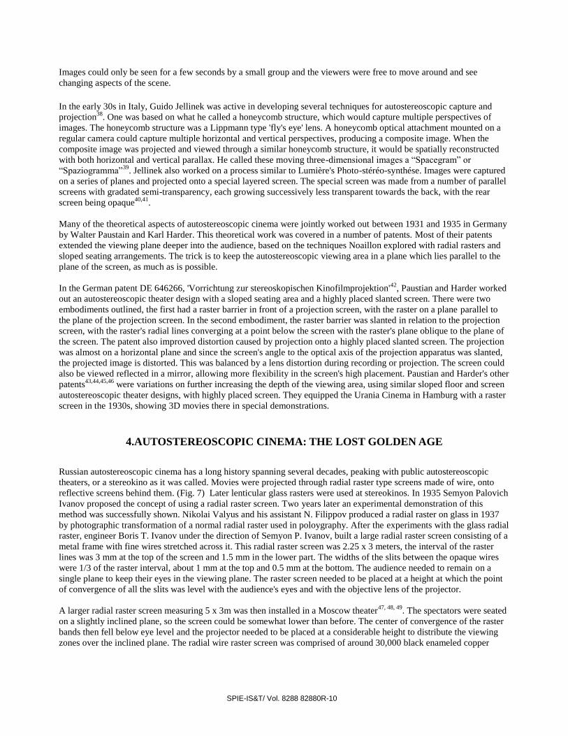
Russian autostereoscopic cinema has a long history spanning several decades, peaking with public autostereoscopic
theaters, or a stereokino as it was called. Movies were projected through radial raster type screens made of wire, onto
reflective screens behind them. (Fig. 7) Later lenticular glass rasters were used at stereokinos. In 1935 Semyon Palovich
Ivanov proposed the concept of using a radial raster screen. Two years later an experimental demonstration of this
method was successfully shown. Nikolai Valyus and his assistant N. Filippov produced a radial raster on glass in 1937
by photographic transformation of a normal radial raster used in poloygraphy. After the experiments with the glass radial
raster, engineer Boris T. Ivanov under the direction of Semyon P. Ivanov, built a large radial raster screen consisting of a
metal frame with fine wires stretched across it. This radial raster screen was 2.25 x 3 meters, the interval of the raster
lines was 3 mm at the top of the screen and 1.5 mm in the lower part. The widths of the slits between the opaque wires
were 1/3 of the raster interval, about 1 mm at the top and 0.5 mm at the bottom. The audience needed to remain on a
single plane to keep their eyes in the viewing plane. The raster screen needed to be placed at a height at which the point
of convergence of all the slits was level with the audience's eyes and with the objective lens of the projector.
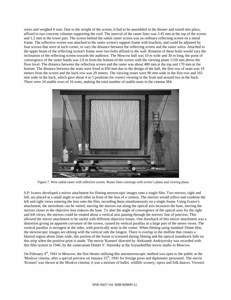
A larger radial raster screen measuring 5 x 3m was then installed in a Moscow theater47, 48, 49
. The spectators were seated
on a slightly inclined plane, so the screen could be somewhat lower than before. The center of convergence of the raster
bands then fell below eye level and the projector needed to be placed at a considerable height to distribute the viewing
zones over the inclined plane. The radial wire raster screen was comprised of around 30,000 black enameled copper
SPIE-IS&T/ Vol. 8288 82880R-11
wires and weighed 6 tons. Due to the weight of the screen, it had to be assembled in the theater and raised into place,
affixed to two concrete columns supporting the roof. The interval of the raster lines was 3.45 mm at the top of the screen
and 1.2 mm in the lower part. The screen behind the radial raster screen was an ordinary reflecting screen on a metal
frame. The reflective screen was attached to the raster screen's support frame with brackets, and could be adjusted by
four screws that were at each corner, to vary the distance between the reflecting screen and the raster wires. Attached to
the upper beam of the reflecting screen's frame were two bolts affixed to the wall. Rotation of these bolts would vary the
inclination of the reflecting screen towards the audience. The Moscow hall was 10 m wide and 30 m long, the point of
convergence of the raster bands was 2.8 m from the bottom of the screen with the viewing plane 1150 mm above the
floor level. The distance between the reflection screen and the raster was about 480 mm at the top and 170 mm at the
bottom. The distance between the seats were fixed at 850 mm due to the design of the hall, the first row of seats was 10
meters from the screen and the back row was 29 meters. The viewing zones were 80 mm wide in the first row and 165
mm wide in the back, which gave about 4 or 5 positions for correct viewing in the front and around two in the back.
There were 24 usable rows of 16 seats, making the total number of usable seats in the cinema 384.
Figure 7. Wire radial-raster with reflective screen. Raster lines converge with screen’s plane and viewing plane.
S.P. Ivanov developed a mirror attachment for filming stereoscopic images onto a single film. Two mirrors, right and
left, are placed at a small angle to each other in front of the lens of a camera. The mirrors would reflect and combine the
left and right views entering the lens onto the film, recording them simultaneously on a single frame. Using Ivanov's
attachment, the stereobase can be varied, moving the mirrors out along the optical axis increases the base, moving the
mirrors closer to the objective lens reduces the base. To alter the angle of convergence of the optical axes for the right
and left views, the mirrors could be rotated about a vertical axis passing through the mirrors' line of junction. This
allowed the mirror attachment to be useful with different objective lenses. One drawback of this mirror attachment was a
distortion giving an apparent curvature of the screen, caused by vertical parallax in a large part of the stereo views. The
vertical parallax is strongest at the sides, with practically none in the center. When filming using standard 35mm film,
the stereoscopic images are oblong with the vertical side the longest. There is overlap in the midline that creates a
blurred region about 2mm wide, this portion of the frame is screened during filming and the optical soundtrack falls on
this strip when the positive print is made. The movie 'Konsert' directed by Aleksandr Andriyevsky was recorded with
this film system in 1940, by the cameraman Dmitri V. Surensky at the Soyuzdetfilm movie studio in Moscow.
On February 4th
, 1941 in Moscow, the first theater utilizing this autostereoscopic method was open to the public at the
'Moskva' cinema, after a special preview on January 25th
, 1941 for foreign press and diplomatic personnel. The movie
'Konsert' was shown at the Moskva cinema; it was a mixture of ballet, wildlife scenery, opera and folk dances. Viewers
SPIE-IS&T/ Vol. 8288 82880R-12
did not have much freedom of head movement, but the movie was a huge success and Semyon P. Ivanov won the State
Laureate Award due to his efforts. The 'Moskva' cinema closed in July of 1941, due to the German invasion of Russia,
only a few months after opening. After the first stereokino closed, S.P. Ivanov improved the film system by allowing the
images to take up a larger area on the frame by having a smaller number of perforations, 35 mm film with a step
perforation of 19 mm. With a quarter of the perforations, the stereoscopic image can be much larger, and the picture will
be square instead of oblong. This improved film system was used in 1945, to record the films “Robinson Crusoe” and
“Machine 22-12”, at the Stereofilm studio.
After the war ended, another stereokino was opened in Moscow on February 20
th, 1947, at the site of the former
“vostokkino”. This new theater had a greatly improved raster screen, a lenticular glass sheet that had nine times the
brightness of the wire radial raster screen. Premiering there was the feature length “Robinson Crusoe” directed by
Aleksandr Andriyevsky, the first stereoscopic feature length color movie ever released. The next movie to be shown
there was “Machine 22-12”, a comedy with lots of sing-along scenes, shots of moving automobiles, landscapes and a
strange magic show scene. The new lenticular raster screen measured 3 x 3 m and was constructed by S.P. Ivanov, Boris
T. Ivanov and E.F. Savchenko. It had raster lines arranged radially in the form of two or three thousand fine conical
lenses that focused light from the projector onto the reflective screen placed behind it. Because the glass lenticular raster
allows very narrow light bands to be formed on the reflecting screen, more than two component stereo images may be
projected onto the screen without any overlap. This allows multiple views to be projected and seen by spectators, up to
10 views in the case of the glass lenticular raster. This is what is known as the 'capacity' of the screen, the wire raster
only had a capacity of 2 to 2.5, incapable of displaying more than one stereoscopic view.
In 1948 the film arrangement was modified again, this time with the intention of compatibility with standard equipment
and conventional printing processes. The soundtrack was moved from the middle to the side, causing a reduction in the
frame size and small loss in quality, a tradeoff in exchange for compatibility. In the summer of 1949, the stereokino in
Moscow had three films on the program, “Crystals”, “Land of the Sun” and “Karandash Na Ldu”. “Crystals” was the
world’s first animated stereoscopic film, featuring an explorer introducing crystals into his hiking, climbing and caving
adventures. “Land of the Sun” or “Solnechnyy Kray“ was a two-toned travelogue of the Crimea, Russia. “Karandash Na
Ldu” was a comedy short, the main character, whose name is Karandash or 'pencil', is a creation of the lead comic
Mikhail Rumyantsev. He gets involved in a hockey match after he is made substitute goal-keeper in a women's ice-
hockey team captained by his love. Besides being autostereoscopic, these movies also made use of stereophonic sound,
spatially relating to the scene's visuals.
Another film format was developed at NIKFI in 1952, comprised of two standard frames measuring 16x22mm, placed
one above the other, with the sound track on one side. This format developed by Nahum B. Berishtein and Andrew G.
Boltyanskii, improved the quality of the image and allowed the soundtrack to be printed and attached to the film by
standard means. For recording films on this new format a new stereoscopic camera was built, based on the PSK-21
camera. Since the frames were now placed one above the other, the mechanism for moving the frame was modified to
tug the film 38mm instead of the standard 19mm, and a larger shutter was added to cover both frames of the stereopair
simultaneously. The optical system was fitted with two demountable objective lenses and a reflecting prism device to
provide a horizontal base line.
The new camera was called the PSK-S stereo-camera. Changing the dimensions or position of the prisms could vary the
base line. Changing the objective lenses varied the size of the image and the width of the field of view. The camera was
supplied with a prism attachment having base lines of 38, 48, 65 and 130 mm. The interchangeable objective lenses have
focal lengths of 35, 50 and 75 mm. Each pair of objective lenses can be simultaneously adjusted for focus and stop. Both
objective lenses could also be shifted horizontally. The PSK-S stereo-camera is fitted with a stereo viewer, as proposed
by Andrew G. Boltyanskii and Nina A. Ovsyannikova. The viewer enables the whole spatial composition of the scene to
be seen and controlled as it is being filmed. The camera operator can see the position of the objects in the scene relative
to the plane of the screen it will be projected upon.
At the beginning of 1954, the new stereoscopic feature film “May Night” was showing at the Moscow Stereokino
Theater. It was director Alexander Rou's adaptation of N.V. Gogol's Ukrainian legend, filmed by cameraman Dmitri
Surensky, most of it in the nighttime under moonlight. In early 1954 the second stereokino was opened in Kiev, and
subsequently over the next few years, stereokinos opened in Leningrad and Astrakhan. Besides “May Night” other
SPIE-IS&T/ Vol. 8288 82880R-13
works have been shown at Russian stereokinos such as “Burbot” based on Anton Chekhov's 1885 treatise on fishing and
“Aleko” based on Rachmaninov's short opera of Pushkin's "Gypsies". Comedies have included “Dragotsennyy Podarok”
aka “Precious Gift”, in which a young man enters a fishing contest to impress his elderly uncle and “Kosolapyy Drug”
aka “Bandy-Legged Friend” comedy about a bear. The stereokinos with lenticular glass raster screens remained open
until the early 60s. At Expo '70 in Osaka, Japan a radial-type lenticular plate that was 3x4m was shown.
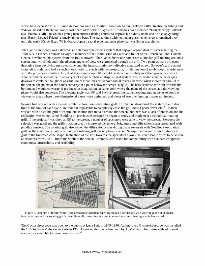
The Cyclostéréoscope was a direct-vision stereoscopic cinema system that enjoyed a good deal of success during the
1940-50s in France. François Savoye, a member of the Commission of Color and Relief of the French National Cinema
Center, developed this system from the 1930s onward. The Cyclostéréoscope comprises a circular grill rotating around a
screen onto which left and right adjacent angles of view were projected through the grill. Two pictures were projected
through a large revolving truncated cone onto the internal stationary reflective metalized screen. Savoyes's grill rotated
from left to right, and had a synchronous motor to synch with the projectors, for elimination of stroboscopic interference
with the projector’s shutters. Any dual strip stereoscopic film could be shown on slightly modified projectors, which
were behind the spectators. It was a type of a type of "barrier strip" or grid system. The truncated cone, with its apex
downward could be thought of as variation of Noaillon's or Ivanov's radial rasters, because when viewed in parallel to
the screen, the points of the bands converge at a point below the screen. (Fig. 8) The bars decrease in width towards the
bottom, and would converge, if produced in imagination, at same point where the plane of the screen and the viewing
plane would also converge. The viewing angle was 40° and Savoye prescribed zoned seating arrangements to confine
viewers to areas where three-dimensional views were optimized and views of two overlapping images minimized.
Savoye first worked with a system similar to Noaillon's oscillating grill in 1934, but abandoned the system due to dead
time at the limit of each cycle. He found it impossible to completely erase the grill during phase reversals50
. He then
worked with a flexible grill of continuous motion that moved around the screen, but there was a lack of precision and the
realization was complicated. Building on previous experience he began to study and implement a cylindrical rotating
grill. If the projector was tilted at 45° to the screen, a number of spectators were able to view the screen. Stereoscopic
selection was good and the grill's rotation greatly improved the general brightness and diffraction issues associated with
parallax barriers. The rotating grill also solved the diffraction issues during phase reversals with Noaillon's oscillating
grill, as the continuous motion of Savoye's rotating grill has no phase reversal. Savoye then moved from a cylindrical
grill to the truncated cone shape. Inclination of the grill towards the spectators allows the stereoscopic effect to be visible
at distances from 2 to 10 times the width of the screen. Attempts were made for compatibility with standard equipment,
economical affordability and scalability.
Figure 8. Diagram of theater with Cyclostéréoscope installed, showing sloped floor design, with viewing plane of audience,
internal screen and the rotating grill's raster lines all converging at a point below the screen. Seating area is fan shaped.
The Cyclostéréoscope was open to the public at Luna Park in 1945-1946. An improved Cyclostéréoscope was installed
the "Clichy Palace" theater in Paris in 1953. Home models were later sold by A. Mattley in four sizes with additional
accessories available to make home movies51
.

SPIE-IS&T/ Vol. 8288 82880R-14
French autostereoscopic camera designer, inventor and photographer extraordinaire Maurice Bonnet further developed
the theory of autostereoscopic cinema techniques. Particular focus was given to correct viewing geometry by eliminating
spatial distortions, theater design and observing the laws of binocular vision. His research, designs and devices related to
autostereoscopic cinema stemmed from his autostereoscopic photography work. He was very concerned with viewer
comfort and proper projection of spatial images. Like Kakabadze before him, in addition to developing techniques and
devices, he created autostereoscopic content. Bonnet's content was in the form of photography. Many decades of images
have been captured by his Bonnet-type camera and widely exhibited, including the World’s Fair in Montreal in 1967 and
the Osaka Expo in 1970. Inspired by the earlier work of Berthier, Kanolt, Estanave, Lippmann and others, he developed
several types of autostereoscopic cameras. He founded the Society Reliéphographie in 1936 for the designing and
creating of machines to photograph and produce relief photographs. Bonnet had several hundred patents worldwide,
many related to autostereoscopic imaging, greatly advancing the art of lenticular camera design, methods of
manufacturing lenticular lenses and printing techniques, much of which is still used in some form today.
Most of his early camera work photographed subjects in an arc, capturing the scene from multiple perspectives as with a
Parallax Panoramagram. Some moved along a track and captured subjects over a period of time, others were capable of
instantaneous capture. The cameras that moved in an arc on a track are called 'scanning-type' cameras, they usually have
a barrier-strip or lenticular screen in the back of the camera. In a one-step dedicated process, they photograph a scene,
the lenticulation is immediately put onto the film during processing. Bonnet also designed a camera that could record
both depth and/or motion. It used a scanning 'selector' mask to record a scene over a short period of time.
Maurie Bonnet was on the Comission supérieure technique du Cinéma and on March 21, 1945 at the National
Conservatory of Arts And Crafts, Bonnet presented a paper outlining the optimal conditions required for comfortable
viewing and proper spatial reconstruction of projected images52
. Three categories of theater viewing were outlined,
'Binocular' viewing of two views from a fixed position, 'Semi-Integral' having horizontal parallax and 'Integral' which
features horizontal and vertical parallax. He developed a set of separate conditions required for each of the three
categories. With the goal of producing as natural of an image as possible, these three categories of spatial representation
have an increasing order of accuracy. He emphasized the need for proper spatial representation though the filmmaker
taking into consideration the space the movie will be watched in.
Figure 9. UNIATEC Congress in Moscow 1964. S. P. Ivanov in center wearing the tie, Maurice Bonnet on the right. (Picture
courtesy Michéle Bonnet)
Bonnet analyzed the properties of reflective screens and assessed their use for projecting in relief. He outlined how to
improve the angle of reflection needed to properly reconstruct spatial images. The angle at which the viewer is looking
at the screen affects the perception of the object’s spatial construction. He isolated a fault common to all metallic screens
at the time, the projection was brighter in the axis of projection. The efficiency of the screen was lowered by
deformation of the neighboring reflective element. He proposed a solution of developing polished optical elements,
limiting deformations during machining of the die, and proposed an autostereoscopic theater based on these concepts.
In the late 1930s the French military became interested in possible applications of his work, particularly in the field of
aerial photography and cryptography. Mécanique et Optique de Précision (1950 – 1960) was the society created by
Maurice Bonnet for developing equipment and materials to make relief photos again, after his leaving the Society
SPIE-IS&T/ Vol. 8288 82880R-15
Reliéphographie. It was at Mécanique et Optique de Précision where he developed an autostereoscopic aerial filming
system for the French military. From the 1950s onward he stayed active in the Comission supérieure technique du
Cinéma, often speaking at cinema conferences on optimal autostereoscopic projection53, 54
. Bonnet traveled to the
UNIATEC Congress in Moscow in 1964 (Fig. 9) to speak on the subject of restoring the sense of space in cinema,
alongside S.P. Ivanov and other innovators. In the US, Douglas Winnek like many others involved in autostereoscopic imaging, worked with autostereoscopic X-ray
photography and also aerial photography. He was a pioneer of lenticular photography who extended the work of
Lippmann, Hess, etc. with several seminal innovations. His Trivision cameras were very successful and used to
photograph many subjects. These cameras were a scanning type, moving across the subject. It could produce an
autostereoscopic image on a single plate, using film embossed on the base side with lenticulations. The lenticulations are
placed in the camera with the lenticulations towards the lens. Winnek also developed a method of projecting images in
relief based on a lenticular screen, outlined in his 1937 patent, “Apparatus for Projecting Pictures in Relief”55
. He later
was the first to realize the benefit of angled lenticules for moiré reduction and images sharpness56
, a technique that is still
used today using flat panel display technology.
Leslie Peter Dudley as far back as 1935 successfully demonstrated autostereoscopic cinematography in Britain, by
means of the Parallax Stereogram principle. Two synchronized projectors were rear projected onto a translucent screen
through a grid, forming alternate left-eye and right-eye vertical strips. The spectators viewed the screen through a second
grid suitably positioned in front of the screen. In 1939, he was granted British Patent No. 514,624, outlining the
construction of a stereoscopic camera suitable for recording Parallax Stereogram images directly onto film with a single
camera. The image on the film itself was in the interlaced form, removing the need for the rear grid used in the previous
version, and allowing use of a single projector. This project was abandoned due to the outbreak of war. Towards the end
of the war, it became possible for Dudley to resume research on autostereoscopic film processes, based on the principle
of the Parallax Panoramagram using a lenticular process57, 58
.
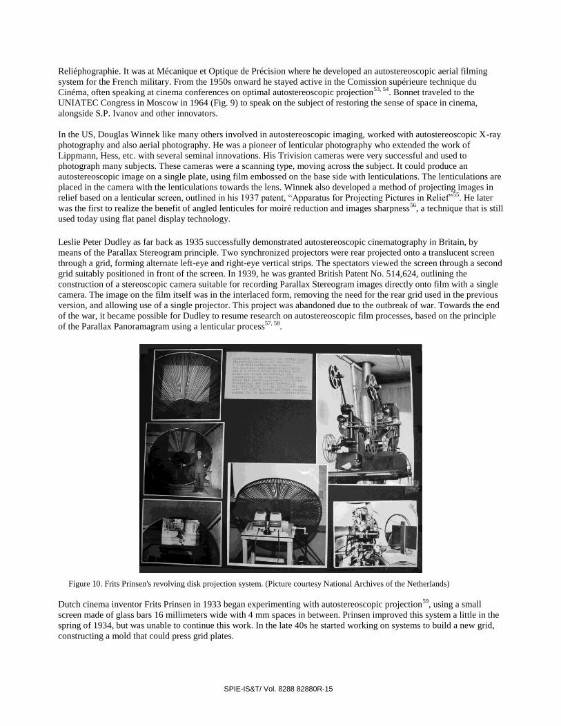
Figure 10. Frits Prinsen's revolving disk projection system. (Picture courtesy National Archives of the Netherlands)
Dutch cinema inventor Frits Prinsen in 1933 began experimenting with autostereoscopic projection
59, using a small
screen made of glass bars 16 millimeters wide with 4 mm spaces in between. Prinsen improved this system a little in the
spring of 1934, but was unable to continue this work. In the late 40s he started working on systems to build a new grid,
constructing a mold that could press grid plates.
SPIE-IS&T/ Vol. 8288 82880R-16
Prinsen started constructing another system from 1950 onwards, based on ideas he had in his mind since the early 1930s.
This system consisted of a radial raster screen in the form of a circular spinning disk. (Fig. 10) The wheel was about
three meters in diameter with alternating plastic lenses and opaque strips. A 30 x 40 cm reflective screen was behind the
raster disk and left/right views were projected though the spinning disk's raster by two side-by-side projectors onto the
reflective screen. He demonstrated this system to the press on November 24, 1950. A larger version with a radial raster
disk 3 meters in diameter with 7.38 cm wide bars was demonstrated on November 22, 1952. Then he began working on
a system that could project three separate images, Left, Right, and Middle, which he called L-M-R. In 1953 Prinsen
succeeded in projecting the three images onto a screen with a radial grid having spokes spaced 11 cm apart.
In 1955 he moved to a rotating truncated conical grid, which revolved around the screen. This design was very similar to
Savoye's Cyclostéréoscope, but later beginning in May 1958, it also used the L-M-R technique. Around this time he
increased the speed of the rotating cone first to 80 rpm and later to 102 rpm, to reduce stroboscopic interference. Frank
Weber also collaborated with Prinsen on the cone system for a couple of years. In 1965 Prinsen showed his invention to
longtime friend Walter Selle, the two would often talk about autostereoscopy. Between 1961 and 1963 he worked on a
smaller version that could be used in the home. Although many admired his work, unfortunately few saw a profitable
investment in it.
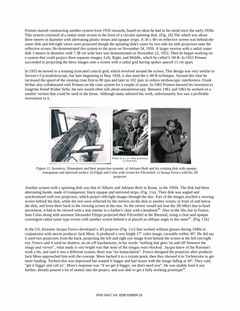
Figure 11. Inventors, filmmakers and their projection systems. a) Adriano Betti and his rotating disk with opaque,
transparent and mirrored surface. b) Filppi and Colas with screen for Filcorelief. c) Jacque Fresco with his 3D
projector.
Another system with a spinning disk was that of Alberto and Adriano Betti in Rome, in the 1950s. The disk had three
alternating bands, made of transparent, black opaque and mirrored strips. (Fig. 11a) Their disk was angled and
synchronized with two projectors, which project left/right images through the disc. Part of the images reached a viewing
screen behind the disk, while the rest were reflected by the mirrors on the disk to another screen, in front of and below
the disk, and from there back to the viewing screen in the rear. So the viewer would not lose the 3D effect due to head
movement, it had to be viewed with a seat similar to a barber's chair with a headrestt60
. Also in the 50s, but in France,
Jean Colas along with assistant Alexandre Filippi projected their Filcorelief at the Biennial, using a clear and opaque
convergent radial raster type screen with another screen behind it at placed an oblique angle to the raster61
. (Fig. 11b)
In the US, Inventor Jacque Fresco developed a 3D projector (Fig. 11c) that worked without glasses during 1940s in
conjunction with movie producer Jack Moss. It produced a very bright 17" color image, viewable within 30°. He did say
it used two projectors from the back, projecting the left and right eye image from behind the screen at the left eye/right
eye. Fresco said it used no shutters, no on-off mechanisms, in his words “nothing that goes 'on and off' between the
image and viewer”, what made it very bright was that none of the images were blocked. Jacque knew of the Russian's
work a bit, and said it was a different system, there was “no lentucilation”. Fresco designed the projector after producer
Jack Moss approached him with the concept. Moss backed it to a certain point, then they showed it to Technicolor to get
more funding. Technicolor was impressed but wanted it bigger and had issues with the image fading at 30°. They said,
"get it bigger and call us". Moss's response was "if we get it bigger, we don't need you". He was unable fund it any
further, already poured a lot of money into the project, and was able to get a fully working prototype62
.

SPIE-IS&T/ Vol. 8288 82880R-17
5.AFTER THE LOST GOLDEN AGE
Engineer Robert Collender's work in stereoscopic imagery began in 1949, most of it focused on techniques without user-
worn viewing aids, with the scene having multiple views. He continued into the millennium working on solving the
issues of autostereoscopic viewing for large audiences. He began with his Stereoptiplexer63, 64, 65, 66
, first comprising a
projection screen inside a large revolving drum with a slit, the projection screen later to be replaced with a special
brushed screen. The Stereoptiplexer would record subjects on a revolving table or scenes with lateral motion onto film.
The Stereoptiplexer was improved over many years, various forms of 3D capture and viewing were explored, including
the “outside-looking-in” and the “inside-looking-out” varieties. Both allow for unaided viewing of stereoscopic images
with freedom of viewer movement, each position providing the viewer with a separate perspective, the ability to 'look
around' images. The “inside-looking-out” variation, first successfully tested in 1960, provides a scene similar to looking
out a window, where viewers could see scenes such as landscapes and distant views. In contrast, the “outside-looking-
in” version can feature an actor or small object, the viewer can walk 360° around the subject, able to see all sides in
unaided stereo. The earliest “outside-looking-in” variation will be described.
For 3D capture of scenes, a standard 8mm camera is used, viewing the scene through a dove or pechan prism. The
subject or object to be captured is placed on a horizontal motorized turntable, with a disk below coupled to the turntable's
shaft. The lower disk has 96 holes, with a lamp above the disk and a photo-electric pickup below. Light is either blocked
by the disk or shines through one of the 96 holes, and as the subject on the turntable rotates, the azimuth is sensed by the
photo-electric pickup. When the photo-electric pickup senses 1/96th of a full rotation, it triggers the camera's shutter.
The camera's shutter is triggered 96 times per revolution of the subject, and the film is advanced an equal number of
times per rotation. The prism in front of the camera is electrically coupled to the rotating turntable, allowing the prism to
rotate in sync with the subject, so that the successive images on the film are rotated 360°/96 with respect to an adjacent
frame. This correction is necessary so that the later reconstructed 3D image is viewable as upright from any azimuth of
view.
Figure 12. Robert Collender's Stereoptiplexer, the mirror-drum version, with special brushed screen. Second image
shows mirror-drum and film path on opened Stereoptiplexer.
For reconstruction of 3D scenes, the images are viewed inside a revolving drum containing a narrow vertical aperture
through which observers could see a scanned 360° reconstruction of the filmed scene. The aperture is 1/96th of the
closure, resulting in reduction of the screen illumination by a factor of 96. To compensate for the brightness reduction,
Collender used a “Fresnel lens-cylindrical lenticule diffuser-sandwich” in place of a translucent screen, to direct all of
the light to the vertical slit. Inside the revolving drum the “Fresnel lens cylindrical lenticule diffuser-sandwich” is used
as the projection surface. Using a high-speed projector, the scenes captured with the turntable system are projected in
succession onto the projection surface inside the drum. The drum is rotated at least 16 times per second to avoid flicker,
and the screen image is always moving parallel to the slit, and a plane passing through the slit always intersects the
screen image at right angles. Just as with capture, the projector displays a frame on the projection surface 1/96th of a
rotation. Since the observer is viewing the screen image through the vertical slit, at any instant in time, one eye will see a
relatively narrow vertical section of the image, and the other eye will see another relatively narrow vertical section of the
image. The two vertical sections are spaced from each other. Because the slit is moving, at a later instant in time, the two
SPIE-IS&T/ Vol. 8288 82880R-18
eyes again see separate portions of the image. The portions of the image viewed by the left and right eye are continually
changing, and each eye never sees what the other eye is viewing at the same instant. The two dissimilar views are
stereoscopically related and fuse inside the brain into a 3D image. His later systems eliminated use of the moving drum,
involving a special brushed screen. (Fig. 12)
In the early 2000s, Collender and his son Michael worked together on another type of autostereoscopic cinema design,
for a screen and theater. This design doesn't record footage exclusively for autostereoscopic viewing, but converts
footage with significant lateral motion into autostereoscopic imagery on the fly using a curved tiled mirror screen. It
could be thought of as an optical real-time 2D to autostereoscopic conversion system that converts the content directly
with the projection and screen configuration.
Homer B. Tilton began his work on synthesized 3D electronic moving images back in the late 1940s. He began with
analog monoscopic perspective scenes that later extended to stereoscopic work, finally to enter the autostereoscopic
realm of infinite parallax. Tilton's early work displayed representations of mathematically based synthetic 3D images
from a 2D perspective on oscilloscope CRTs. Images were represented electronically in the form of dynamic signals of
varying voltages, in the same manner as XY scanning on oscilloscopes but with an added axis. Analog circuits were
developed which accepted three inputs, X, Y, and Z, which would mathematically transform three arbitrary dynamic
signals into two dynamic signals. These two signals were fed separately into the oscilloscope's X and Y inputs,
displaying an electronic perspective drawing representing the arbitrary XYZ signals in real-time.
In the 1950s Tilton extended this work to include expanded transforms of the dynamic X, Y and Z signals and developed
a separate system which displayed stereoscopic representations of three dynamic signals side by side on a single CRT,
viewed with a stereoscope-like attachment. Additional development continued in the early 60s on the monoscopic
perspective display. The analog electronic transformations grew into an extend family of modular form, developing into
a highly versatile system for displaying interactive electronic perspective drawings in real-time. By the mid-60s this was
developed into a product called the Scenoscope.
In the late 60s he came across an article by Robert Collender on the Stereoptiplexer. Homer wondered if the screen
inside the rotating drum of the Stereoptiplexer, onto which film is projected, could be replaced by a CRT. After
contacting Collender on that possibility, he received a short but positive response. This was enough for him to try to
make it happen, and he did succeed with his Parallactiscope67, 68, 69, 70, 71
.
The Parallactiscope is an autostereoscopic display using 4 main components: an electrostatically deflected CRT, a
Parallax Scanner, a Parallax Computer, and a Scanner Driver. (Fig. 13) The Parallax Scanner is an electronically
controlled direction-sensitive spatial filter placed in front of the CRT. The Parallax Scanner is constructed with two
crossed linear polarizers and a vertical sliver of half-wave retarder in the center. The crossed polarizers block the light
coming from the CRT, but with the .10 inch sliver of half-wave retarder in the center, after the light passes through the
first linear polarizer and the half-wave retarder, the light is rotated 90° and then is able to pass through the subsequent
linear polarizer. This forms a virtual slit that allows only particular light rays to pass into observer space while blocking
all others. The sliver of half-wave retarder is mounted on a high-Q pendulum connected on its other end to a small audio
loudspeaker. The speaker acts as a linear drive motor, allowing the virtual slit to scan horizontally in front of the CRT. If
the slit moves side to side fast enough, it is no longer perceived as a slit.
The Parallax Scanner slit's horizontal motion is driven by the Scanner Driver with a sinusoidal signal. A second
sinusoidal signal with the same frequency, but variable phase, feeds into the Parallax Computer. The Parallax Computer
is a special purpose analog computer, which accepts x, y, and z deflection signals and processes them to provide the
proper horizontal and vertical deflection signals for the CRT. Since the Parallax Computer receives a signal from the
Parallax Scanner, it is able to keep track of the slit's instantaneous horizontal position at all times. As the CRT screen is
viewed through the slit, each narrow vertical zone on the CRT screen is keyed to a unique horizontal viewing direction.
This configuration allows controlled parallax: the Parallax Computer processes the x, y, and z signals in relation to the
slit's instantaneous position, displaying the proper image on the CRT, which, when viewed through the Parallax Scanner,
produces autostereoscopic images. Autostereopsis is produced, along with infinite views within 90°, with no
pseudoscopic zones.

SPIE-IS&T/ Vol. 8288 82880R-19
Figure 13. Homer B. Tilton’s Parallactiscope. a) Large Parallax Scanner with one linear polarizer removed to show slit and
pendulum. b) Large screen electrostatically deflected CRT in front of Parallax Scanner. c) Parallax Computer with Scanner Driver on
top.
The 3D image displayed on the Parallactiscope represents the X, Y, and Z deflection signals fed into the Parallax
Computer. All images are directly drawn onto the display; there is no raster. The CRT must be electrostatically deflected
to obtain a sufficient redraw speed, and must have a high intensity, short persistence phosphor. High intensity is required
due to some loss of brightness with the slit; the short persistence helps avoid smearing.
A varifocal mirror display72
uses a reflective Mylar film stretched over a rigid ring, mounted in front of a loudspeaker.
The loudspeaker is driven sinusoidally at low frequencies, usually around 30hz. As the mirror vibrates the reflective
Mylar membrane’s surface flexes from concave to convex. The mirror becomes a moving surface, and due to the
concave/convex nature of the mirror’s movement, the perceived movement of the reflected images in the mirror is much
greater than the mirror’s actual physical movement. High-speed images are displayed on a CRT, consisting of ‘slices’,
which are reflected off the vibrating mirror. These slices are similar to Lumiere’s Photo-stereo-synthesis “slices”. The
‘slice stacking’ is done on the varifocal mirror by displaying on the CRT a succession of slices in synchronicity with the
sinusoidal signal driving the mirror’s loudspeaker. For example, if the mirror is driven at 30hz and ‘slices’ are displayed
on the CRT at the rate of 3000 fps, there would be 100 slices. The slices need to be displayed in the proper progression
during each cycle of the mirror’s sweep, in order to be correctly represented spatially.
In the US during the late 1960s, Video artist and technical wizard Sid Washer briefly experimented with a varifocal
mirror. He was already working with a modified TV that modulated the deflection directly, allowing XY scanning. First
working with a reticule, he projected light through the reticule, directly reflected off the mirror instead of being projected
into an intermediate screen. An amplifier drove an incandescent lamp behind the reticule, so he had in effect a voltage
controlled light source. The scan signal feeding the vibrating mirror’s loudspeaker was also modulating the light source.
Since the lamp was modulated by the same signal driving the mirror, it produced a static three-dimensional image, due to
its dynamically changing brightness. The image's shape was the typical cross pattern on a reticule, but in 3D. The mirror
was next used with the modified TV reflected off the mirror. He used a combination of both music and several sinusoidal
oscillators to modulate the XY deflection of the CRT, the mirror, the CRT beam’s brightness, and separate modulation
of RGB values. The music was usually pre-processed with tunable bandpass filters, dividing the spectrum into low, mid
and high frequency ranges. The output signals from the filters were then used as individual modulation sources. Low
frequencies could modulate the red, middle frequencies the green and high frequencies the blue, all this being
changeable with a rotary switch. He usually used two driving signals to control overall brightness. Washer was able to
display various forms of three-dimensional Lissajous figures. The signal driving the mirror was usually sinusoidal, and
needed to be mixed in with one of the signals modulating the CRT’s XY deflection beams. This was required in order to
produce stable images. This process is not an example of ‘slice stacking’, but another method of changing 2D images
along the z-axis to create a spatial image. The first mirror he worked with was 5”, before building a larger display with a
12” speaker.
Since 1974, holographic cinema research has been conducted in Russia at NIKFI, led by Professor Victor G. Komar. The
research group produced monochromatic holographic movies73
in 1976 and color holographic movies74
in 1984. The
images were recorded on film and projected onto a holographic screen capable of focusing and multiplying the image to
create multiple viewing zones. The American Academy of Motion Picture Arts and Sciences awarded NIKFI an Oscar in

SPIE-IS&T/ Vol. 8288 82880R-20
1991 for these innovations and in 2002 The Russian Academy of Cinematographic Arts awarded Professor Komar the
Nika.
The monochromatic system was demonstrated in 1976 at the UNIATEC Congress in Moscow, on a holographic screen
0.6 x 0.8 meters. The screen had four viewing zones in which a moving holographic scene was observed of a young
woman holding a bouquet of flowers, in a yellow monochromatic hue. The movie was about 47-seconds long and when
viewers moved side to side they could see the whole face behind the bouquet. Another holographic movie demonstrated
around that time featured a Byzantine scene of a woman pouring jewels into a wine glass.
To provide a wide viewing zone, large aperture lenses are used for shooting and projection. A special camera with a lens
about 200 mm in diameter records indoors scenes using pulsed laser light. 70mm film is used for recording. The film
moves at a rate of about one meter per second through the camera. In bursts of 50 nanoseconds, the pulsed laser is
reflected by the subject and passes through the lens, which focuses the image on the film plane. From interference at the
film plane by the object beam and a reference beam from the same laser, a hologram diffraction grating is formed.
The 70mm film must have a sensitivity of two to four microjoules per square centimeter, high diffraction efficiency and
a low level of noise. Extremely high-powered pulsed lasers are not necessary, as the wide aperture lens admits a high
degree of light and a reference beam also strikes the film. Even though the film is slow, it receives sufficient light for
exposures of acceptable speed. To prevent the potential harmful flickering of laser light to performers at low frequencies,
incoherent light can be used. The camera's shutter is open only for the period of the pulse, to eliminate the effect of the
incoherent light. Additionally for recording outdoor scenes with incoherent light, the researchers at NIKFI developed a
method using a scanning type camera with non-holographic film. The images from the scene could then be converted to
holographic form, as with a holographic stereogram. The researchers also looked at composite methods of coherent and
incoherent recording for special effects.
There are two methods of printing the film, a lensless and optical method. The lensless method places the exposed film
near the print film, a single reference beam of coherent light passes through the exposed film which forms a spatial
image on the print film. The optical method places a lens between the exposed film and the print film. This has the
advantage that it ensures reversal of the image and allows separate control of the intensities of the object beam and the
reference beam, for optimal choice of ratio.
There were three versions of screens for viewing holographic movies. With the first and second versions the projection
was performed immediately on a multiplying point-focusing holographic screen up to 1 x 0.8 m in size. The first version
of the holographic screen for monochromatic projection had up to five viewing zones, the second holographic screen for
colored projections had two viewing zones. With the third version, projection was made onto a mirror-film round
vacuum screen 2 m in diameter. The light beam from the projector fell onto an intermediate holographic screen. The
screen reflected 24 separate beams, which were directed and focused on 24 mirror lenses, directing and focusing the
beams onto the large mirror-film vacuum screen. Beams reflected from the screen formed 24 viewing zones.
Two different projectors were also developed. They had lenses with a focal length of 250 mm and an aperture of 200
mm. With the first projector lasers were used, the second one used a mercury-cadmium lamp. The projector with the
laser gives a larger depth and greater image sharpness, but was complex. The projector with the mercury-cadmium lamp
was simpler and cheaper, but its depth was low.
Komar and the NIKFI team were determined to opening holographic movie theaters within a few years after their initial
research. The Gorky Film Studio in Moscow began shooting the first 20-minute holographic movie in 1986 and
simultaneously the USSR government approved plans for the first holographic movie theater with 50 seats. Then with
the major restructuring of Russia's economy in the late 1980s, state financing of holographic cinema R&D was
terminated. Rolan Bykov, a very prominent filmmaker in Russia, became interested in filming the first feature
holographic movie in the late 90s. Bykov started negotiations with Komar's NIKFI laboratory and begun raising money
to build a holographic theater, but his sudden death ended the project. Kormar's plan to create a 30-minute film for an
audience of three hundred never materialized.

SPIE-IS&T/ Vol. 8288 82880R-21
In France, English sculptor Alexander worked with the laboratory of Paul Smigielski to create in 1986, an 80-second
holographic movie called "The Beauty and the Beast". It was inspired by Jean Cocteau’s 1945 “La Belle et La Bête”.
Smigielski’s laboratory was at the French-German Research Institute known as ISL. The holographic movie was
recorded on 126 mm film with a pulsed YAG laser. Each pulse was synchronized with a new frame to be exposed in the
camera. The movie was not very bright, and spectators had to look through a small aperture to watch it. It also featured a
musical suite in medieval style, written by Alexander75
.
Professor Smigielski has previously made a holographic movie “Christiane and the Holobubbles” in August 1985 at ISL.
Seen is the movie’s “star” Christiane blowing soap bubbles. It was made with a pulsed laser, recorded on 126 mm film.
The movie lasts just one minute and is viewable by only one person at a time. Made with a reel of 1000 holographic
frames, it was viewed through a small window; the film reel was arranged on a turning cylinder. After disappointment
with the limitations of the previous medium used to film "The Beauty and the Beast", Alexander worked with integral
holograms, shot by Sharon McCormack. Instead of using integral holograms in their cylindrical form, they were
unwound and spliced together in a roll. He would splice together as many as 14 in a roll. A simple mechanism rolled the
holograms from right to left through a 7" X 9" window. A lens in front of the hologram enlarged the images to
approximately 12" X 16". One such movie in 1987 was the 8-minute long “The Dream”, with original music composed
by Alexander. “The Dream” had loosely linked sequences, such a dancing couples, ballerinas, and a child playing with
cubes76
.
Claudine Eizykman and Guy Fihman created several holographic movies using a glass plate process and also 126 mm
film. These movies were done at the Laboratoire d'expérimentations dans les arts cinégraphiques and the National Centre
for Scientific Research in France. On April 22, 1982, at the "Les Immatériaux" exhibition held at Collège de France they
premiered their holographic film “Vols d'oiseaux”. This date was chosen because it was the 100th
anniversary of Jules-
Etienne Marey recording 12 frames of birds in flight with his "chronophotographic gun”. As homage to Marey, “Vols
d'oiseaux” featured animated bronze gulls in flight, using 20 images on a glass plate. In 1985 in Paris they exhibited a
second holographic movie “Un Nu”, a palindrome in French for “a nude”. A mummy unwinds its bands to reveal a nude
woman, and the viewer could push a button to play the movie backwards. The image was viewed through a small
window and due to the shortcomingsof the low power YAG laser used, didn’t have the same brightness as the "Vols
d'oiseaux”77
.
In the early 1990s, this author put together a system for creating, performing and displaying autostereoscopic animations
in synchronicity with live or recorded music. It originally started as a system to be performed on like an instrument,
allowing improvisation of autostereoscopic animations in synchronicity with music, later evolving into other forms of
artistic expression. The content, techniques and to a degree the hardware involved are loosely known as Hologlyphics.
Most early work with Hologlyphics was displayed on Homer B. Tilton's Parallactiscope, plus some additional work with
varifocal mirrors. I first developed a digitally controlled analog autostereoscopic image synthesis system based on image
generators and processors. It allowed real-time synthesis and control of spatial primitives using analog modules such as
the Helix Generator which used a sin/cosine oscillator in conjunction with a ramp generator to generate the three xyz
waveforms necessary to display a three dimensional helix. The generated images, in the form of three dynamic arbitrary
waveforms, could be subsequently transformed by image processing modules. The image processing modules would
accept three inputs and have three or more outputs, depending on function. The inputs and outputs of the synthesis and
processing modules were all patched into a digitally controlled analog switching matrix.
Tilton build the first displays for me, also helping develop analog volumetric special effect processors, such as the
Hyperbolic Paraboloid Generator with “coniod modification”. It electronically transformed the helix patterns into a
hyperbolic paraboloid, sphere or an original 'spaceform' of Tilton's called a 'conoid'. Turning its controls, a sphere
gradually transforms into a cone of two napes. When the knob is in the middle position, a 'conoid' is formed. Despite the
primitive nature of the early Hologlyphics system, it produced an amazing variety of autostereoscopic flowing imagery,
geometry and endless patterns. Even with the Helix Generator by itself in it's simplicity, sweeping the frequency
produced a enchanting recoil effect. It also allowed real-time control by a performer and interaction with sound. I
traveled with the system to many places, setting it up and showing animations. The Parallactiscope has super high
resolution monochromatic imagery, infinite parallax, producing high density spatial imagery.

SPIE-IS&T/ Vol. 8288 82880R-22
Figure 14. Hologlyphics on a Parallactiscope display. The moving images can be controlled in real-time as a performance, interact
with sound and have infinite parallax.
In the mid 90s, I worked on expanding the system for larger audiences, increased complexity of imagery and the addition
of color. Work with lasers for color addition and size increase proved to be difficult for adaptation to the Parallactiscope
design78
. “Volumetric Overscan” in 1996 was an attempt at an autostereoscopic music video, featuring animations to the
music of Fifty Foot Hose. The system's design was later updated for digital image generation and control, producing a
much greater variety of imagery, sound, and interaction79
. (Fig. 14) This included special effects made specifically for
animations or movies viewed on multiview autostereoscopic and volumetric displays. The volumetric special effects80
extended traditional special effects such as wipes, into spatial wipes movable in any direction, and included new special
effects specific to multiview autostereoscopic movies, such as “volume bending”. The Hologlyphic animations have
been shown at many events since 1994, including the San Francisco International Arts Festival, California Academy of
Sciences, the Exploratorium along with holography pioneers Lloyd Cross, Greg Cherry, and Peter Claudius, yearly
exhibits at the Maker Faire, plus many film festivals and art galleries81, 82
.
The recent introduction of commercially available autostereoscopic displays has widened the possibility of creating
moving autostereoscopic art and entertainment. The "Espace des Sciences" Rennes, France, showed an autostereoscopic
3D movie shot with 8 cameras in the summer of 2005. It was displayed on a commercially available 40-inch Alioscopy
screen. The movie was part of an exhibition about gorillas. The gorillas appeared to be right in front of the visitors, as if
the spectators were looking through a window in the animal park where the movie was shot. Video artist Arcane has
several times used multiple commercial autostereoscopic displays at live events. A Small crew shot an autostereoscopic
version of the German fairytale "Rumpelstilzchen" in Cologne during the beginning of 2008, using a camera array with 5
Point Grey cameras. The crew included director and cinematographer Nils Trümpener, Sound engineer Friedrich
Wohlfahrth, German actor/puppeteer Jürgen Wicht and Bernhard Schipper. (Fig. 15) The potential for creating content
without jumping through technical hurdles is growing and the future is wide open. The development of higher quality
displays in the future will open the door even wider, removing current viewing and resolution limitations.
6.CONCLUSION
Autostereoscopic cinema has a strong history going back to a time when cinema was in its infancy. The medium still has
many limitations, despite nearly a century of growth. Inventors and artists have continually borrowed from each other,
sometimes across great distances, to realize this vision. Earlier autostereoscopic techniques based on parallel line
networks evolved into radial rasters and dynamic parallax barriers installed in special theaters, to put real 3D on the big
screen. In addition to parallax barriers, a multitude of autostereoscopic imaging techniques has been applied to the visual
arts. A variety of content has been shown internationally, many times the creative individuals also needed to develop
their own imaging systems or work with those who have. From fringe inventors and eccentric artists, to Nobel Prize
winners, a strong foundation has been built. The methods of showing content have been a huge technical challenge and
undertaking, yet many dedicated individuals have contributed to its progress.

SPIE-IS&T/ Vol. 8288 82880R-23
Figure 15. Behind the scenes at the 5 camera shoot for "Rumpelstilzchen".
Acknowledgments
Michéle Bonnet, daughter of Maurice Bonnet, scanned many technical papers and photographs from
the Maurice Bonnet archive, on his cinema work in relief. Michel Ketelaars supplied information on
Frits Prinsen's autostereoscopic systems, from an upcoming book on Prinsen he is writing along with
Harm Pieters. Giorgi Gersamia of The Georgian Museum of Photography supplied the photograph of
David Kakabadze's spectacles-free cinema prototype. Kim Timby provided a picture of the
Cyclostéréoscope in action. Robert Collender provided materials and photographs from his archive.
REFERENCES
[1]Claudet, A., “On the Phenomenon of Relief of the Image Formed on the Ground Glass of the Camera Obscura”,
Proceedings of the Royal Society of London, Vol. 8, pp. 569-572 (1856 - 1857)
[2]Claudet, A., "On The Stereomonoscope, a new Instrument by which an apparently Single Picture produces the
Stereoscopic Illusion", Proceedings Of The Royal Society Of London, pp. 194-196 (March 10, 1858)
[3]“A New Kind of Miniature”, The Intellectual Observer: Review of Natural History, Microscopic Research and
Recreative Science, Volume IV, p 292-293 (August 1863)
[4]Swan, Henry, “Improvements in stereoscopic apparatus”, British Patent 3249 (1862)
[5]Swan, Henry, “Casket Miniatures in Relief. On Printing Coloring and Mounting The Transparencies”, The
Photographic News, p 248, London (May 25, 1866)
[6]Maxwell, James Clerk, “Note on a real-image stereoscope”, The Quarterly Journal of Pure and Applied Mathematics,
footnote p. 115 in "On the cyclide" (1868)
[7]Berthier, Auguste, "Images stéréoscopiques de grand format", Cosmos, 34 (590, 591): 205–210, 227-233 (see 229-
231), (May 16 and 23, 1896)
[8]Jacobson, John, “Pictorial Reproduction”, US Patent 624042 (1899)
[9]Jacobson, John, “Stereograph”, US Patent 624043 (1899)
[10]Ives, Frederic E., “Parallax stereogram and process of making same”, U.S. Patent 725567 (1903)
[11]Ives, Frederic E., “Process of Making Line Composite Stereoscopic Photographs”, US Patent 761679 (1904)
[12]Ives, Frederic E., "A novel stereogram", Journal of the Franklin Institute, Vol. CLIII, No1, p 51–52 (1902)
[13]Estanave, E., “Le relief stéréoscopique en projection par les réseaux lignés”, Comptes rendus des séances de
l’Académie des Sciences, vol 143, 29, p.p. 644-647 (October 1906)
[14]Timby, Kim, “Images en relief et images changeantes, La photographie à réseau ligné”, Études photographiques,
No. 9, p 124-143 (May 2001)

SPIE-IS&T/ Vol. 8288 82880R-24
[15]Lippmannn, G., "Épreuves réversibles. Photographies intégrales", Comptes Rendus de l'Académie des Sciences,
146, (9), pp:446–451 (March 2 1908)
[16]Sokolov, P. P., “Autostereoscopy and Integral Photography By Professor Lippmann’s Method”, Lyubiteley
Yestestvoznaniya, 123, pp 23-29 (1911)
[17]Hess, Walter, “Improved manufacture of stereoscopic pictures”, UK Patent 13,034 (1912)
[18]Hess, Walter, “Verfahren zur Herstellung von Stereoskopbildern“, AT65020 (1914)
[19]Kanolt, Clarence W., “Photographic Method and Aparatus”, US Patent 1260682 (1918)
[20]Lumiére, Louis, “Représentation photographique d'un solide dans l'espace. Photo-stéréo-synthése”, Comptes
Rendus de l'Académie des Sciences (Nov. 8, 1920)
[21]Reynaud, Francoise, Catherine Tambrun, and Kim Timby, [Paris in 3D: From Stereoscopy to Virtual Reality 1850-
2000], London, Booth-Clibborn Editions (2000)
[22]Kakabadze, David, “Stéréo-cinématographe donnant la vision du relief naturel”, French Patent 547978 (1922)
[23]Kakabadze, David, “Stéréocinématographe”, French Patent 563486 (1923)
[24]Kakabadze, David, “Improvements in or relating to Stereoscopic Kinematography”, British Patent 223476 (1924)
[25]Kakabadze, David, “Installation stéréocinématographique”, Swiss Patent 111576 (1925)
[26]Noaillon, E., “Procede De Projection Cinematographique Stereoscopique”, Belgian Patent 347554 (1927)
[27]Noaillon, E., “Art of Making Cinematographic Projections”, US Patent 1772782 (1928)
[28]Noaillon, E., “Construction d'une Salle Stéréoscopique”, Technique Ciné, p 1086 (December 1937)
[29]Noaillon, E., “Art Of Making Stereoscopic Projections”, US Patent 2198678 (1940)
[30]Hamery, Roxane, [Jean Painlevé le cinéma au coeur de la vie], Rennes: Presses Universitaires de Rennes (2008)
[31]Savant, Cinéaste, “Un quart d'heure avec Jean Painlevé“, Journal de Tournon et d'Annonay, No. 33, (August 13,
1939)
[32]Ives, H. E., “Motion Pictures In Relief”, Opt. Sot. Amer., 18, pp 118-122 (February, 1929)
[33]Ives, H. E., “Projection of Stereoscopic Pictures”, US Patent 1883290 (1932)
[34]Ives, H. E., “Stereoscopic Motion Picture”, US Patent 2012995 (1935)
[35]Ives, H. E., "Parallax Panoramagrams Made With A Large Diameter Lens", J. Opt. Soc. Am. 20, 332-340 (1930).
[36]Ives, H. E., "Parallax Panoramagrams Made With A Large Diameter Concave Mirror", J. Opt. Soc. Am., 20, 597-
599 (1930)
[37]Ives, H., "Making Stereoscopic Parallax Panoramagrams from Pseudoscopic Parallax Panoramagrams”, US Patent
1905716 (1933)
[38]Jellinek, Guido, [Due nuovi sistemi di cinematografia in rilievo], Milano, Libreria editrice politecnica (1932)
[39]Jellinek, Guido, “Alcune considerazioni sulla fotografia tridimensionali per proiezioni centrali”, Il Politecnico,
Issue 4 (April 1933)
[40]Jellinek, Guido, “Nuovo processo fotografico”, Il Politecnico, Issue 2 (February 1935)
[41]Jellinek, Guido, “Method of Three-Dimensional Photography and Cinematography”, British Patent 409663 (1934)
[42]Paustian, W. and Harder, Karl. M., “Vorrichtung zur stereoskopischen Kinofilmprojektion”, German Patent 646266
(1937)
[43]Paustian, W. and Harder, Karl. M., “Verfahren zur Erzielung stereoskopischer Projektion”, German Patent 626087
(1936)
[44]Paustian, W. and Harder, Karl. M., “Vorrichtung zur stereoskopischen Kinematographie”, German Patent 635146
(1936)
[45]Paustian, W. and Harder, Karl. M., “Einrichtung zur Projektion von stereoskopischen Bildern”, German Patent
686005 (1940)
[46]Paustian, W. and Harder, Karl. M., “Beweglicher Raster fuer den Projektionsschirm zur Stereoprojektion”, German
Patent 666541 (1938)
[47]Valyus, N. A., [Stereoscopy] London, Focal Press (1966)
[48]Valyus, N. A., [Rastrovye opticheskie pribory], Moskva Mashinostroenie (1966)
[49]Valyus, N. A., [Rastrovaya optika], Gostekhizdat (1949)

SPIE-IS&T/ Vol. 8288 82880R-25
[50]Savoye, F., "Cyclostéréoscope" procédé de cinéma en relief à vision collective directe sans lunettes”, Atti e
rassegna tecnica della Società degli ingegneri e degli architetti in Torino; nuova serie, No. 12 (1952)
[51]Linssen, E.F, “The cyclostereoscope”, The British Journal of Photography, Vol XCIX, No. 4827, p 575 (Novmeber
21, 1952)
[52]Bonnet, M., "Le Cinema En Relief", bulletin de la Commission Supérieure Technique, vol.1, No, 2, pp 45 - 64
(1945)
[53]Bonnet, M., “Les conditions de restitution dans le cinéma en relief", Bulletin de l'AFITEC, No. 13, pp 5 - 18 (1954)
[54]Bonnet, M., "La troisième dimension et la projection cinématographique", Revue Internationale de Filmologie, vol.
VI, No. 20-24, Presses Universitaires de France, pp 24 -28 (1955)
[55]Coffey, D. F. W., “Apparatus for Projecting Pictures in Relief”, US Patent 2100634 (1937)
[56]Winnek, D. F., “Composite Stereography”, US Patent 3409351 (1968)
[57]Dudley, Leslie, “Stereoscopic Kinematograph”, Canadian Patent 375097 (1938)
[58]Dudley, Leslie P., [Stereoptics; An Introduction], London, Macdonald (1951)
[59]Ketelaars, Michel & Pieters, Harm, Upcoming book on F. B. A Prinsen (2013)
[60]Limbacher, James L., [Four Aspects of the Film], New York: Brussel & Brussel (1969)
[61]“Une grande salle de Paris va lancer le cinéma en relief sans lunettes", Paris Match, No. 298 (May 1954)
[62]Personal communication, Jacque Fresco
[63]Collender, R. B., "Recent Developments in Stereo without Glasses", American Cinematographer, p 650, (Oct,
1965)
[64]Collender, Robert B., “Three dimensional unaided viewing method and apparatus”, US Patent 3178720 (1965)
[65]Collender, R. B., "The Stereoptiplexer", Information Display, vol. 4, no. 6, pp 27-31, (Nov/Dec, 1967)
[66]Collender, R.B., "True Stereoscopic Movie System Without Glasses", Part 1, Information Display, vol. 5, no. 4, pp
25-38 (July/Aug 1968)
[67]Tilton, H. B., "Real-Time Direct-Viewed CRT Displays Having Holographic Properties", Proceedings of the
Technical Program, Electro-Optical Systems Design Conference, pp 415-422, 18-20 (1971)
[68]Tilton, H. B., "An Autostereoscopic CRT Display", Three Dimensional Imaging. Proc. SPIE Vol. 120, p 68-72
(1977)
[69]Tilton, H., "Nineteen Inch Parallactiscope", Three Dimensional Imaging. Proc. SPIE Vol. 902, p 17-23 (1988)
[70]Tilton, H., "Everyman's real time real 3D", Three Dimensional Visualization and Display Technologies. Proc. SPIE
Vol. 1083, pp 76-82 (1989)
[71]Tilton, H. B., [The 3D Oscilloscope], Prentice Hall, Englewood Cliffs (1987)
[72]Traub, A., "Stereoscopic display using rapid varifocal mirror oscillations", Appl. Opt. 6, pp 1085-1087 (1967)
[73]Komar, Victor, “Progress on the Holographic Movie Process in the USSR”, SPIE Vol. 120, pp 127–44 (1977)
[74]Komar, Victor, “Works on the Holographic Cinematography in the USSR”, SPIE Vol. 1183, pp 170–182 (1990)
[75]Alexander, P., "Development of integral holographic motion pictures", Proc. SPIE 2333, 187 (1995)
[76]Vacca, John R., [Holograms and Holography: Design, Techniques, & Commercial Applications], Hingham, MA:
Charles River Media (2001)
[77]Prédal, René, & Eizykman, Claudine & Fihman, Guy, “Le Cinéma holographique: les expérimentations de
Claudine Eizykman et Guy Fihman”, Cinémas: revue d'études cinématographiques, vol. 1, no. 3, pp 61-76 (1991)
[78]Tilton, H. B., “True 3-D for your computer”, Computer Wrangler, Vol. 5, No. 4, Echo Press, Tuscon (1997)
[79]Funk, W., "Hologlyphics: Volumetric image synthesis performance system", Proc. SPIE, vol. 6803, Int'l Soc. for
Optical Eng., Stereoscopic Displays and Applications XIX (2008)
[80]Funk, W., “Volumetric Special Effects”, Veritas et Visus, Double Issue 25 & 26 (2008)
[81]Malshefshi, Tiffany, “Visual Sound“, The San Francisco Examiner, p 22 (Feb. 19, 2009)
[82] Van Dyke, Michelle Broder, “A Hologlyphic Story“, San Francisco Bay Guardian, Vol. 44, No. 33, p 37 (May 19-
25, 2010)