history module service - honeywell · section 5 – test/troubleshooting ... 5.3.4 smcc/detailed...
TRANSCRIPT
�
History Module Service
HM13-501


LCN Service - 2
History Module Service
HM13-501 Release 530
CE Compliant 12/02

12/02 History Module Service ii
Copyright, Notices, and Trademarks
© Copyright 1995 - 2002 by Honeywell
Revision 08 – December, 2002
While this information is presented in good faith and believed to be accurate, Honeywell disclaims the implied warranties of merchantability and fitness for a particular purpose and makes no express warranties except as may be stated in its written agreement with and for its customer.
In no event is Honeywell liable to anyone for any indirect, special or consequential damages. The information and specifications in this document are subject to change without notice.
TotalPlant and TDC 3000 are U.S. registered trademarks of Honeywell Inc.
Honeywell International Industry Solutions
16404 N. Black Canyon Highway Phoenix, AZ 85053
1-800-343-0228

12/02 History Module Service iii
About This Publication This publication provides instructions for use by the maintenance personnel to service a WREN III type History Module, a WREN III type History Module that has been upgraded with the 210 megabyte (MB), 445 megabyte (MB), 875 megabyte (MB), 1.8 gigabyte (GB) Winchester disk drive(s), or a WDA type History Module that contains either the 210 megabyte, 445 megabyte, 875 megabyte, 1.8 gigabyte (GB), dual logical 875 MB or dual logical 1.8 GB Winchester Disk drive(s). This publication will assist you in determining how to service the History Module, identifying spare parts, and disassembling and reassembling the History Module when replacing a defective part. This publication supports TotalPlant Solution (TPS) system Release 530 and earlier software releases. TPS is the evolution of TDC 3000X. This publication supports CE Compliant equipment. Any equipment designated as “CE Compliant” complies with the European Union EMC and its health and safety directives. All equipment entering the European countries after January 1, 1996 require this type of compliance, denoted by the “CE Mark.”
TECHNICAL ASSISTANCE
If you need assistance If you need technical assistance, contact your local Honeywell Service
Organization, as explained in the following paragraphs.
International customers
Outside of the United States, contact your local Honeywell Service Organization. If you are not sure of the location or telephone number, call your Honeywell representative for information.
Customers inside the United States
Within the United States, call the Technical Assistance Center (TAC) at the toll free number 1-800-822-7673.
Arizona customers Within Arizona, the local number for TAC is 602-313-5558.
Services provided Calls to TAC are answered by a dispatcher from 7:00 A.M. to 5:00 P.M., Mountain Standard Time (6:00 A.M. to 4:00 P.M. when daylight saving time is in effect). Outside of these hours, emergency calls—those which affect your ability to control or view a process—will be received by an answering service, and returned within one hour. TAC maintains its own TPS system, and frequently can duplicate equipment problems.
Time saving tip It is a good idea to make specific notes about the problem before making the call. This will help to reduce delays and expedite answers.

12/02 History Module Service iv
Standard Symbols
Scope The standard symbols used in this publication are defined as follows.
ATTENTION Notes inform the reader about information that is required, but not
immediately evident.
CAUTION Cautions tell the user that damage may occur to equipment if proper care is not exercised.
WARNING Warnings tell the reader that potential personal harm or serious economic loss may happen if instructions are not followed.
53893
OR
Ground connection to building safety ground.
53894
Ground stake for building safety ground.
53895
DANGERSHOCK HAZARD
Electrical Shock Hazard—can be lethal.
53896
DANGERHIGH VOLTAGE
Electrical Shock Hazard—can be lethal.
53897
Rotating Fan—can cause personal injury.
!
Caution—refer to the appropriate installation document.

12/02 History Module Service v
Table of Contents
SECTION 1 – INTRODUCTION........................................................................................15 1.1 Overview.....................................................................................................15 1.2 Support Services and Documents ..............................................................17
SECTION 2 – WREN TYPE HISTORY MODULE DESCRIPTION ..................................19 2.1 Overview.....................................................................................................19 2.2 Nonredundant Drive History Modules.........................................................21 2.2.1 WREN III History Module Description.........................................................21 2.2.2 210/445/875 MB and 1.8 GB History Module Description ..........................27 2.3 Redundant Drive History Modules ..............................................................33 2.3.1 Redundant Single Disk Drive Configuration ...............................................35 2.3.2 Redundant Dual Drive Configuration..........................................................38
SECTION 3 – WDA TYPE HISTORY MODULE WITH TYPE I DRIVE............................41 3.1 Overview.....................................................................................................41 3.3 Physical Configuration ................................................................................47 3.4 Circuit Board Configuration ........................................................................49 3.5 Nonredundant Drive History Module Configuration ....................................50 3.5.1 Single Disk Drive Configuration..................................................................50 3.5.2 Dual Disk Drives Configuration...................................................................52 3.6 Redundant Drives History Module Configuration........................................54 3.6.1 Single Disk Drive Configuration..................................................................55 3.6.2 Dual Disk Drives Configuration...................................................................57 3.7 Field Adjustments .......................................................................................59
SECTION 4 – WDA HISTORY MODULE WITH TYPE II DRIVE TRAY...........................61 4.1 Overview.....................................................................................................61 4.3 Physical Configuration ................................................................................67 4.4 Circuit Board Configuration ........................................................................69 4.5 Nonredundant Drive History Module Configuration ....................................70 4.5.1 Type II Disk DrivesConfiguration ................................................................70 4.6 Redundant Drives History Module Configuration........................................73 4.6.1 Type II Disk Drives Configuration ...............................................................74 4.7 Field Adjustments .......................................................................................76
SECTION 5 – TEST/TROUBLESHOOTING ....................................................................77 5.1 Overview.....................................................................................................77 5.2 Test Strategy ..............................................................................................77 5.3 Troubleshooting..........................................................................................80 5.3.1 Preliminary Checks.....................................................................................80 5.3.2 Sequential Troubleshooting........................................................................81 5.3.3 Maintenance Recommendations................................................................85 5.3.4 SMCC/Detailed Module Error Messages....................................................87 5.3.5 Real Time Journal (RTJ) Messages...........................................................93 5.3.6 Repair Strategy...........................................................................................94 5.3.7 Data Error Recovery Technics and Documentation ...................................96 5.3.8 Nonredundant Drive Data Error Recovery..................................................97 5.3.9 Redundant Drive Data Error Recovery....................................................103 5.3.10 Control Track Error Recovery for Sectors 1-31 ........................................106 5.3.11 Status Detail Display.................................................................................108 5.3.12 Volume Status Display..............................................................................110 5.3.13 Sector Initialization/Reassignment Procedure..........................................113
SECTION 6 – WREN TYPE HISTORY MODULE DISASSEMBLY ...............................117

12/02 History Module Service vi
6.1 Overview .................................................................................................. 117 6.2 Electronics Module Disassembly ............................................................. 118 6.3 Nonredundant Winchester Drive Module Disassembly............................ 119 6.3.1 Fan Assembly Removal ........................................................................... 120 6.3.2 Slide Tray Assembly Removal ................................................................. 120 6.3.3 Power Supply/Disk Drive Removal .......................................................... 121 6.4 Redundant Winchester Drive Module Disassembly................................. 122 6.4.1 Fan Assembly Removal ........................................................................... 123 6.4.2 Slide Tray Assembly Removal ................................................................. 123 6.4.3 Power Supply/Disk Drive Removal .......................................................... 124
SECTION 7 – WDA TYPE I HISTORY MODULE DISASSEMBLY ............................... 125 7.1 Overview .................................................................................................. 125 7.2 History Module Disassembly.................................................................... 126 7.2.1 General Disassembly............................................................................... 127 7.2.2 Fan Assembly Removal ........................................................................... 128 7.2.3 Power Supply Removal ............................................................................ 128 7.2.4 Circuit Board Removal ............................................................................. 129 7.2.5 Winchester Disk Assembly Removal ....................................................... 130 7.3 Winchester Drive Tray Disassembly........................................................ 131 7.3.1 Winchester Disk Drive Removal .............................................................. 134
SECTION 8 – WDA HISTORY MODULE WITH DUAL LOGICAL DRIVE TRAY DISASSEMBLY ....................................................................................... 151
8.1 Overview .................................................................................................. 151 8.2 History Module Disassembly.................................................................... 152 8.2.1 General Disassembly............................................................................... 153 8.2.2 Fan Assembly Removal ........................................................................... 154 8.2.3 Power Supply Removal ............................................................................ 154 8.2.4 Circuit Board Removal ............................................................................. 155 8.2.5 Winchester Disk Assembly Removal ....................................................... 156 8.3 Winchester Drive Tray Disassembly........................................................ 157 8.3.1 Winchester Disk Drive Removal .............................................................. 160
SECTION 9 – WREN TYPE HISTORY MODULE ASSEMBLY..................................... 161 9.1 Overview .................................................................................................. 161 9.2 Electronics Module Assembly .................................................................. 162 9.3 Winchester Drive Module Assembly ........................................................ 163 9.3.1 Fan Replacement..................................................................................... 164 9.3.2 Power Supply Replacement ..................................................................... 164 9.3.3 Disk Drive Replacement .......................................................................... 164 9.3.4 Slide Tray Assembly................................................................................. 168 9.4 Nonredundant WREN III Drive Installation............................................... 169 9.4.1 Smart Peripheral Controller (SPC) and SPC I/O Boards ......................... 169 9.4.2 Single/Dual WREN III Drive Pinning ........................................................ 170 9.4.3 Single/Dual WREN III Drive Cabling ........................................................ 172 9.5 Nonredundant 210/445/875 MB and 1.8 GB Drive Installation ................ 175 9.5.1 Smart Peripheral Controller (SPC) and SPC I/O Boards ......................... 176 9.5.2 Single/Dual 210 MB Drive Pinning ........................................................... 177 9.5.3 Single/Dual 445 MB Drive Pinning ........................................................... 182 9.5.4 Single/Dual 875 MB Drive Pinning ........................................................... 187 9.5.5 Single/Dual 1.8 GB Drive Pinning ............................................................ 193 9.5.6 Single/Dual 210/445/875 MB or 1.8 GB Drive Cabling............................. 197 9.6 Redundant WREN III Drive Installation.................................................... 202 9.6.1 Single Drive Installation............................................................................ 203 9.6.1.1 Single WREN III Drive Pinning................................................................. 203 9.6.1.2 Single WREN III Drive Cabling................................................................. 205 9.6.2 Dual Drive Installation .............................................................................. 209 9.6.2.1 Dual WREN III Drive Pinning ................................................................... 209 9.6.2.2 Dual WREN III Drive Cabling ................................................................... 211 9.6.2.2 Dual WREN III Drive Cabling, Continued................................................ 213

12/02 History Module Service vii
9.7.1 Redundant Single Drive Installation..........................................................214 9.7.1.1 Single 210 MB Drive Pinning ....................................................................214 9.7.1.2 Single 445 MB Drive Pinning ....................................................................218 9.7.1.3 Single 875 MB Drive Pinning ....................................................................221 9.7.1.4 Single 1.8 GB Drive Pinning .....................................................................227 9.7.1.5 Single 210/445/875 MB or 1.8 GB Drive Cabling .....................................230
SECTION 10 – WDA TYPE HISTORY MODULE ASSEMBLY......................................233 10.1 Overview...................................................................................................233 10.2 History Module Assembly .........................................................................235 10.2.1 General Assembly ....................................................................................235 10.2.2 Fan Assembly Replacement.....................................................................236 10.2.3 Power Supply Replacement .....................................................................236 10.2.4 Circuit Board Replacement.......................................................................237 10.2.5 Cabling Replacement ...............................................................................246 10.2.6 Winchester Disk Assembly Replacement ................................................247 10.3 Winchester Disk Assembly Reassembly..................................................248 10.4 Winchester Drive Tray Assembly .............................................................249 10.4.1 General Information..................................................................................249 10.4.2 Winchester Disk Drive Replacement........................................................251
SECTION 11 – DUAL LOGICAL WDA HISTORY MODULE ASSEMBLY....................267 11.1 Overview...................................................................................................267 11.2 History Module Assembly .........................................................................269 11.2.1 General Assembly ....................................................................................269 11.2.2 Fan Assembly Replacement.....................................................................270 11.2.3 Power Supply Replacement .....................................................................270 11.2.4 Circuit Board Replacement.......................................................................271 11.2.5 Cabling Replacement ...............................................................................280 11.2.6 Winchester Disk Assembly Replacement ................................................281 11.3 Winchester Disk Assembly Reassembly..................................................282 11.4 Winchester Drive Tray Assembly .............................................................283 11.4.1 General Information..................................................................................283 11.4.2 Winchester Disk Drive Replacement........................................................285
SECTION 12 – STARTUP ..............................................................................................287 12.1 Overview...................................................................................................287 12.2 Visual Checks...........................................................................................287 12.2.1 WREN Type History Module.....................................................................287 12.2.2 WDA Type History Module .......................................................................288 12.3 Power-on Procedure.................................................................................289 12.3.1 Component Replacement Startup ............................................................290 12.3.2 Nonredundant Drive Replacement Startup...............................................292 12.3.3 Redundant Drive Replacement Startup....................................................294 12.4 Redundant Disk Drive Data Synchronization............................................294 12.5 Winchester Disk Drive Formatting............................................................296 12.5.1 Drive Formatting Procedure .....................................................................297
SECTION 13 – SPARE PARTS ......................................................................................301 13.1 Overview...................................................................................................301 13.2 Replaceable Parts Lists............................................................................301
12/02 History Module Service viii
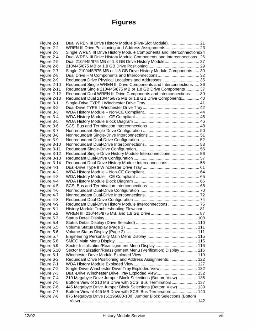
Figures
Figure 2-1 Dual WREN III Drive History Module (Five-Slot Module) ........................... 21 Figure 2-2 WREN III Drive Positioning and Address Assignments ............................. 23 Figure 2-3 Single WREN III Drive History Module Components and Interconnections24 Figure 2-4 Dual WREN III Drive History Module Components and Interconnections . 26 Figure 2-5 Dual 210/445/875 MB or 1.8 GB Drive History Module.............................. 27 Figure 2-6 210/445/875 MB or 1.8 GB Drive Positioning ............................................ 29 Figure 2-7 Single 210/445/875 MB or 1.8 GB Drive History Module Components...... 30 Figure 2-8 Dual Drive HM Components and Interconnections.................................... 32 Figure 2-9 Redundant Drive Physical Locations and Addresses ................................ 35 Figure 2-10 Redundant Single WREN III Drive Components and Interconnections ..... 36 Figure 2-11 Redundant Single 210/445/875 MB or 1.8 GB Drive Components ............ 37 Figure 2-12 Redundant Dual WREN III Drive Components and Interconnections........ 39 Figure 2-13 Redundant Dual 210/445/875 MB or 1.8 GB Drive Components............... 40 Figure 3-1 Single-Drive TYPE I Winchester Drive Tray .............................................. 41 Figure 3-2 Dual-Drive TYPE I Winchester Drive Tray................................................. 42 Figure 3-3 WDA History Module – Non-CE Compliant................................................ 44 Figure 3-4 WDA History Module – CE Compliant ....................................................... 45 Figure 3-5 WDA History Module Block Diagram ......................................................... 46 Figure 3-6 SCSI Bus and Termination Interconnections ............................................. 48 Figure 3-7 Nonredundant Single-Drive Configuration ................................................. 50 Figure 3-8 Nonredundant Single-Drive Interconnections ............................................ 51 Figure 3-9 Nonredundant Dual-Drive Configuration .................................................... 52 Figure 3-10 Nonredundant Dual-Drive Interconnections ............................................... 53 Figure 3-11 Redundant Single-Drive Configuration....................................................... 55 Figure 3-12 Redundant Single-Drive History Module Interconnections......................... 56 Figure 3-13 Redundant Dual-Drive Configuration ......................................................... 57 Figure 3-14 Redundant Dual-Drive History Module Interconnections ........................... 58 Figure 4-1 Dual-Drive Type II Winchester Drive Tray ................................................. 61 Figure 4-2 WDA History Module – Non-CE Compliant................................................ 64 Figure 4-3 WDA History Module – CE Compliant ....................................................... 65 Figure 4-4 WDA History Module Block Diagram ......................................................... 66 Figure 4-5 SCSI Bus and Termination Interconnections ............................................. 68 Figure 4-6 Nonredundant Dual-Drive Configuration .................................................... 70 Figure 4-7 Nonredundant Dual-Drive Interconnections ............................................... 72 Figure 4-8 Redundant Dual-Drive Configuration ......................................................... 74 Figure 4-9 Redundant Dual-Drive History Module Interconnections ........................... 75 Figure 5.1 History Module Troubleshooting Flowchart................................................ 81 Figure 5.2 WREN III, 210/445/875 MB, and 1.8 GB Drive .......................................... 87 Figure 5.3 Status Detail Display ................................................................................ 108 Figure 5.4 Status Detail Display (Drive Selected) ..................................................... 110 Figure 5.5 Volume Status Display (Page 1) .............................................................. 111 Figure 5.6 Volume Status Display (Page 2) .............................................................. 111 Figure 5.7 Engineering Personality Main Menu Display............................................ 115 Figure 5.8 SMCC Main Menu Display ....................................................................... 115 Figure 5.9 Sector Initialization/Reassignment Menu Display .................................... 116 Figure 5.10 Sector Initialization/Reassignment Menu (Verification) Display ............... 116 Figure 6-1 Winchester Drive Module Exploded View ................................................ 119 Figure 6-2 Redundant Drive Positioning and Address Assignments......................... 122 Figure 7-1 WDA History Module Exploded View....................................................... 127 Figure 7-2 Single-Drive Winchester Drive Tray Exploded View ................................ 132 Figure 7-3 Dual-Drive Winchester Drive Tray Exploded View................................... 132 Figure 7-4 210 Megabyte Drive Jumper Block Selections (Bottom View) ................. 136 Figure 7-5 Bottom View of 210 MB Drive with SCSI Bus Terminators...................... 137 Figure 7-6 445 Megabyte Drive Jumper Block Selections (Bottom View) ................. 139 Figure 7-7 Bottom View of 445 MB Drive with SCSI Bus Terminators...................... 140 Figure 7-8 875 Megabyte Drive (51196680-100) Jumper Block Selections (Bottom
View) ..................................................................................................... 142

12/02 History Module Service ix
Figure 7-9 875 Megabyte Drive (51196680-200) Jumper Block Selections (Bottom View)......................................................................................................145
Figure 7-10 1.8 Gigabyte Drive Jumper Block Selections (Bottom View)....................148 Figure 8-1 WDA History Module Exploded View .......................................................153 Figure 8-2 Single-Drive Winchester Drive Tray Exploded View.................................158 Figure 9-1 Winchester Drive Module Exploded View.................................................163 Figure 9-2 Assembly of Drive Shock Mount Hardware ..............................................165 Figure 9-3 Assembly of Adapter Plate to Drive..........................................................166 Figure 9-4 Mounting the 210/445/875 MB or 1.8 GB Drive........................................167 Figure 9-5 SPC Board Address Pinning for SCSI Bus Address ................................169 Figure 9-6 Single WREN III Drive Configuration and Termination (Nonredundant) ..170 Figure 9-7 Dual WREN III Drive Configuration and Termination (Nonredundant) .....171 Figure 9-8 SCSI Cable Routing for Single WREN III Drive........................................172 Figure 9-9 Single WREN III Drive SCSI Cable Installation ........................................173 Figure 9-10 SCSI Cable Routing for Dual WREN III Drives ........................................174 Figure 9-11 SPC Board Address Pinning for SCSI Bus Address ................................176 Figure 9-12 Terminated 210 MB Drive 5 Jumper Block Selections (Bottom View) ....178 Figure 9-13 Bottom View of 210 MB Drive with SCSI Bus Terminator Modules
Installed .................................................................................................179 Figure 9-14 Nonterminated 210 MB Drive 3 Jumper Block Selections (Bottom View)181 Figure 9-15 Terminated 445 MB Drive 5 Jumper Block Selections (Bottom View) ....183 Figure 9-16 Bottom View of 445 MB Drive with SCSI Bus Terminator Modules
Installed .................................................................................................184 Figure 9-17 Nonterminated 445 MB Drive 3 Jumper Block Selections (Bottom View)186 Figure 9-18 Terminated 875 MB Drive 5 (51196680-100) Jumper Block Selections ..188 Figure 9-19 Terminated 875 MB Drive 5 (51196680-200) Jumper Block Selections ..189 Figure 9-20 Nonterminated 875 MB Drive 3 (51196680-100) Jumper Block Selections191 Figure 9-21 Nonterminated 875 MB Drive 3 (51196680-200) Jumper Block Selections192 Figure 9-22 Terminated 1.8 GB Drive 5 Jumper Block Selections (Bottom View).......194 Figure 9-23 Nonterminated 1.8 GB Drive 3 Jumper Block Selections (Bottom View) .196 Figure 9-24 Single 210/445/875 MB or 1.8 GB Drive SCSI Cable Routing (Top View)198 Figure 9-25 Single 210/445/875 MB or 1.8 GB Drive SCSI Bus Cable Routing (Side
View)......................................................................................................199 Figure 9-26 Dual 210/445/875 MB or 1.8 GB Drive SCSI Cable Routing (Side View) –200 Figure 9-28 Redundant Drive Positioning and Address Assignments .........................202 Figure 9-29 Redundant Single WREN III Drive Configuration .....................................204 Figure 9-30 Redundant Single WREN III Drive SCSI Bus Cable Routing (Side View) 205 Figure 9-31 Terminator/Card Guide Assembly ............................................................206 Figure 9-32 Redundant Single WREN III Drive SCSI Bus Cable Installation (Front
View)......................................................................................................207 Figure 9-33 Redundant Single WREN III Drive SCSI Bus Cable Installation (Top
View)......................................................................................................208 Figure 9-34 Redundant Dual WREN III Drive Configuration........................................210 Figure 9-35 Redundant Dual WREN III Drive SCSI Bus Cable Routing (Side View) ..212 Figure 9-36 Redundant Dual WREN III Drive SCSI Cable Installation (Top View)......213 Figure 9-37 Redundant 210/445/875 or 1.8 GB Drive Positioning...............................214 Figure 9-38 Nonterminated 210 MB Drive 5 Jumper Block Selections (Bottom View) 216 Figure 9-39 Nonterminated 210 MB Drive 4 Jumper Block Selections (Bottom View) 217 Figure 9-40 Nonterminated 445 MB Drive 5 Jumper Block Selections (Bottom View) 219 Figure 9-41 Nonterminated 445 MB Drive 4 Jumper Block Selections (Bottom View) 220 Figure 9-42 Nonterminated 875 MB Drive 5 (51196680-100) Jumper Block Selections222 Figure 9-43 Nonterminated 875 MB Drive 4 (51196680-100) Jumper Block Selections223 Figure 9-44 Nonterminated 875 MB Drive 5 (51196680-200) Jumper Block Selections225 Figure 9-45 Nonterminated 875 MB Drive 4 (51196680-200) Jumper Block Selections226 Figure 9-46 Nonterminated 1.8 GB Drive 5 Jumper Block Selections (Bottom View) .228 Figure 9-47 Nonterminated 1.8 GB Drive 4 Jumper Block Selections (Bottom View) .229 Figure 9-48 Redundant Single 210/445/875 MB or 1.8 GB Drive SCSI Bus Cable
Routing ..................................................................................................231 Figure 9-49 Redundant Single 210/445/875 MB or 1.8 GB Drive SCSI Bus Cable
Installation (Top View)...........................................................................232 Figure 10-1 WDA History Module Exploded View .......................................................235 Figure 10-2 SCSI Bus Address Pinning on SPC Circuit Board....................................238 Figure 10-3 K2LCN Board (51401551-x00) LCN Node Address Selection .................240
12/02 History Module Service x
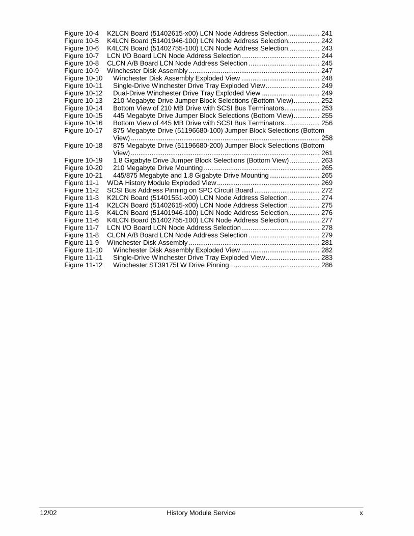
Figure 10-4 K2LCN Board (51402615-x00) LCN Node Address Selection................. 241 Figure 10-5 K4LCN Board (51401946-100) LCN Node Address Selection................. 242 Figure 10-6 K4LCN Board (51402755-100) LCN Node Address Selection................. 243 Figure 10-7 LCN I/O Board LCN Node Address Selection.......................................... 244 Figure 10-8 CLCN A/B Board LCN Node Address Selection ...................................... 245 Figure 10-9 Winchester Disk Assembly ...................................................................... 247 Figure 10-10 Winchester Disk Assembly Exploded View .......................................... 248 Figure 10-11 Single-Drive Winchester Drive Tray Exploded View............................. 249 Figure 10-12 Dual-Drive Winchester Drive Tray Exploded View ............................... 249 Figure 10-13 210 Megabyte Drive Jumper Block Selections (Bottom View).............. 252 Figure 10-14 Bottom View of 210 MB Drive with SCSI Bus Terminators................... 253 Figure 10-15 445 Megabyte Drive Jumper Block Selections (Bottom View).............. 255 Figure 10-16 Bottom View of 445 MB Drive with SCSI Bus Terminators................... 256 Figure 10-17 875 Megabyte Drive (51196680-100) Jumper Block Selections (Bottom
View) ..................................................................................................... 258 Figure 10-18 875 Megabyte Drive (51196680-200) Jumper Block Selections (Bottom
View) ..................................................................................................... 261 Figure 10-19 1.8 Gigabyte Drive Jumper Block Selections (Bottom View) ................ 263 Figure 10-20 210 Megabyte Drive Mounting .............................................................. 265 Figure 10-21 445/875 Megabyte and 1.8 Gigabyte Drive Mounting........................... 265 Figure 11-1 WDA History Module Exploded View....................................................... 269 Figure 11-2 SCSI Bus Address Pinning on SPC Circuit Board ................................... 272 Figure 11-3 K2LCN Board (51401551-x00) LCN Node Address Selection................. 274 Figure 11-4 K2LCN Board (51402615-x00) LCN Node Address Selection................. 275 Figure 11-5 K4LCN Board (51401946-100) LCN Node Address Selection................. 276 Figure 11-6 K4LCN Board (51402755-100) LCN Node Address Selection................. 277 Figure 11-7 LCN I/O Board LCN Node Address Selection.......................................... 278 Figure 11-8 CLCN A/B Board LCN Node Address Selection ...................................... 279 Figure 11-9 Winchester Disk Assembly ...................................................................... 281 Figure 11-10 Winchester Disk Assembly Exploded View .......................................... 282 Figure 11-11 Single-Drive Winchester Drive Tray Exploded View............................. 283 Figure 11-12 Winchester ST39175LW Drive Pinning ................................................ 286

12/02 History Module Service xi
Tables
Table 1-1 Winchester Disk Drive Capacities ..............................................................16 Table 5.1 History Module Reset Procedure................................................................78 Table 5.2 Troubleshooting Procedure – History Module Operates Intermittently.......79 Table 5.3 Troubleshooting Procedure – History Module Will Not Boot ......................82 Table 5.4 Troubleshooting Procedure – Kernel Circuit Board Alphanumeric Display
is -1xx ......................................................................................................83 Table 5.5 Troubleshooting Procedure – History Module Node Status Errors.............84 Table 5.6 Maintenance Recommendation Messages ................................................86 Table 5.7 WREN III, 210/445/875 MB, and 1.8 GB Drive...........................................87 Table 5.8 Drive Primary and Secondary Error Codes ................................................89 Table 5.9 Drive Sense Keys/Sense Codes.................................................................90 Table 5.10 WREN III, 210/445/875 MB, and 1.8 GB Drive Recommended
Corrective Action .....................................................................................92 Table 5.11 Real Time Journal (RTJ) Messages........................................................93 Table 5.12 History Module Error Recovery Reference Manuals ...............................97 Table 5.13 History Module Personality Loading Procedure ......................................98 Table 5.14 Data Error Recovery Procedure – Init/Reload Not Required.................101 Table 5.15 Data Error Recovery Procedure – Init/Reload Required .......................102 Table 5.16 Redundant Drive Data Error Recovery Procedure – .............................103 Table 5.17 Redundant Drive Data Error Recovery Procedure – .............................104 Table 5.18 Drive 5 or 3 Control Track Error Recovery Procedure – Redundant
Drives ....................................................................................................106 Table 5.19 Drive 4 or 2 Control Track Error Recovery Procedure – Redundant
Drives ....................................................................................................106 Table 5.20 Drive 5 or 3 Control Track Error Recovery Procedure – .......................107 Table 5.21 Accessing the Status Detail Display Procedure ....................................108 Table 5.22 Volume Status Display Access Procedure ............................................110 Table 5.23 Volume Status Display Status ...............................................................112 Table 5.24 Initialize/Reassign Sector Procedure ....................................................114 Table 7-1 210 Megabyte Drive SCSI Device Address Selection ..............................135 Table 7-2 445 Megabyte Drive SCSI Device Address Selection ..............................138 Table 7-3 875 MB Drive (51196680-100) SCSI Bus Address Selection...................141 Table 7-4 875 MB Drive (51196680-200) SCSI Bus Address Selection...................144 Table 7-5 1.8 Gigabyte Drive SCSI Device Address Selection.................................147 Table 10-1 210 Megabyte Drive SCSI Device Address Selection ...........................251 Table 10-2 445 Megabyte Drive SCSI Device Address Selection ...........................254 Table 10-3 875 MB Drive (51196680-100) SCSI Bus Address Selection ...............257 Table 10-4 875 MB Drive (51196680-200) SCSI Bus Address Selection ...............260 Table 10-5 1.8 Gigabyte Drive SCSI Device Address Selection .............................262 Table 12-1 Restarting a WREN Type History Module Procedure – Component
Replacement .........................................................................................290 Table 12-2 Restarting a WDA Type History Module Procedure – Component
Replacement .........................................................................................291 Table 12-3 Restarting a WREN Type History Module Procedure – Nonredundant
Drive Replacement................................................................................292 Table 12-4 Restarting a WDA Type History Module Procedure – Nonredundant
Drive Replacement................................................................................293 Table 12-5 Restarting a WREN Type History Module Procedure – Redundant
Drive Replacement................................................................................294 Table 12-6 Restarting a WDA Type History Module Procedure – Redundant Drive
Replacement .........................................................................................294 Table 12-7 Redundant Drives Data Synchronization Procedure .............................295 Table 12-8 HVTS SCMD Test 21 Procedure ..........................................................297 Table 12-9 SCMD Test 21 Parameters ...................................................................298 Table 13-1 WREN Type Drive History Module Parts List ........................................302 Table 13-2 WDA Type Drive History Module Parts List...........................................303

12/02 History Module Service xii
Acronyms
Bit Binary 1 or 0 Byte Eight data bits CRC Cyclic Redundancy Check ECC Error Correction Code GB Gigabyte HMI History Module Initialization HMO History Module Operating HVTS Hardware Verification Test System LCN Local Control Network LED Light Emitting Diode NCF Network Configuration File NCF Network Configuration File ORU Optimum Replaceable Unit PWB Printed Wire Board RTJ Real Time Journal SCMD Smart Controller Magnetic Disk SMCC System Maintenance Control Center TAC Technical Assistance Center WDA Winchester Disk Assembly
12/02 History Module Service xiii
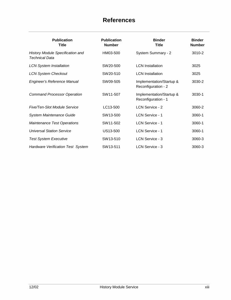
References
Publication Title
Publication Number
Binder Title
Binder Number
History Module Specification and Technical Data
HM03-500 System Summary - 2 3010-2
LCN System Installation SW20-500 LCN Installation 3025
LCN System Checkout SW20-510 LCN Installation 3025
Engineer’s Reference Manual SW09-505 Implementation/Startup & Reconfiguration - 2
3030-2
Command Processor Operation SW11-507 Implementation/Startup & Reconfiguration - 1
3030-1
Five/Ten-Slot Module Service LC13-500 LCN Service - 2 3060-2
System Maintenance Guide SW13-500 LCN Service - 1 3060-1
Maintenance Test Operations SW11-502 LCN Service - 1 3060-1
Universal Station Service US13-500 LCN Service - 1 3060-1
Test System Executive SW13-510 LCN Service - 3 3060-3
Hardware Verification Test System SW13-511 LCN Service - 3 3060-3

12/02 History Module Service xiv

12/02 History Module Service 15
Section 1 – Introduction
1.1 Overview
Section contents The topics covered in this section are:
Topic See Page 1.1 Overview 17 1.2 Support Services and Documents 19
The manual’s purpose This manual provides instructions and references for maintenance, test,
troubleshooting and repair of the TPS system WREN type or WDA type History Module (HM).
WREN type History Module description
The WREN type History Module includes an electronics module and one or two Winchester Drive Modules. The electronics module consists of a Five-Slot Module or one Local Control Network (LCN) node of a Dual Node Module (original WREN III type History Modules only). The electronics module interfaces to one or two Winchester Drive Modules and contains functional circuit boards, associated I/O circuit boards, a fan assembly, and a power supply. The Winchester Drive Module contains one or two Winchester Disk drives, a fan assembly, and a power supply.
WREN III type History Module
Software Release 520 supports only the WREN III type of History Module. The WREN I and WREN II types of History Modules are not supported by the software or this manual.
WREN III upgrade The WREN III type of History Module can be upgraded to accommodate
one or more 210 megabyte (MB), 445 megabyte (MB), 875 megabyte (MB), or 1.8 gigabyte (GB) , dual logical 875 MB or 1.8 GB drive(s) while using WREN III History Module components, such as SPC and SPC I/O circuit boards, and a SCSI bus ribbon cable.
WDA type History Module description
The WDA type History Module, which is packaged in a Five-Slot Module chassis, includes the following basic components. • Local Control Network (LCN) node electronics • Winchester disk drive controller electronics • one, two, or four 3 1/2-inch Winchester disk drives
Continued on next page

12/02 History Module Service 16
1.1 Overview, Continued
WDA History Module contents
The WDA History Module consists of:
• Functional circuit boards and associated I/O circuit boards • A Winchester Disk Assembly (WDA) that occupies two card slots and
contains one or two Winchester Drive Trays. One or two 3.5-inch Winchester disk drives are mounted on the Winchester Drive Trays.
• A fan assembly and an enhanced power supply
WDA Drive Tray One or two Winchester Drive Trays, resident in the Winchester Disk
Assembly, contain one or two 3.5-inch Winchester hard disk drives that are formatted for 256 bytes per sector. The drive has a maximum storage capacity of approximately 210 megabytes, 445 megabytes, 875 megabytes, or 1.8 gigabytes (GB) where a megabyte is a unit of 1,024,000 bytes, and a gigabyte is 1,024,000,000 bytes.
Type II WDA Drive Tray
Each drive tray holds one hard drive that looks like two hard drives when placed in the WDA HM. A drive pinned as SCSI ID 5 looks like 5/3. A drive pinned as SCSI ID 4 looks like 4/2. The drive acts as a pair of dual drives with a capacity of two 875 MB or two 1.8 GB drives and so the History Module must be configured as a Dual Drive HM.
Drive capacities Although the WREN III type drive is physically much larger in size than
the than the 210 megabyte, 445 megabyte, 875 megabyte, and 1.8 gigabyte Winchester disk drives, its formatted storage capacity in megabytes (MBs) is considerably less. The 210 megabyte, 445 megabyte, 875 megabyte, and 1.8 gigabyte Winchester disk drives are small in physical size, only 3 1/2 inches, but they have a much larger storage capacity than the WREN III drive. The drives’ formatted capacities, where a megabyte is a unit of 1,024,000 bytes, are listed in Table 1-1. Table 1-1 Winchester Disk Drive Capacities
Drive Type Capacity in Megabytes Single Drives
Formatted Dual Drives Formatted
WREN III 136.90 273.80 210 Megabyte 215.04 430.08 445 Megabyte 454.13 908.26 875 Megabyte 896.04 1792.08 1.8 Gigabyte 1882.93 3765.86
Continued on next page

12/02 History Module Service 17
1.1 Overview, Continued
Redundant drive configurations
History Modules with WREN III, 210/445/875 MB, or 1.8 GB drives can be assembled in a “redundant disk drive” configuration. The configuration allows software to “synchronize” a redundant drive with its active primary drive partner in such a way that the same data is written to both drives almost simultaneously. If one of the drives fails, its partner becomes the active drive until the failed drive is repaired or replaced. The design of the redundant disk drive History Module permits power to remain on the active drive(s) while the failed drive is being replaced.
Troubleshooting, disassembly, and assembly
The troubleshooting, disassembly, and assembly procedures presented are effective down to the replacement part level. A spare parts lists is included and is keyed to an exploded figure view that can be used for the disassembly and assembly procedures.
1.2 Support Services and Documents
Support documents Honeywell support documents are either required or will be of assistance
during checkout, startup, and operation of the system. They are referenced at the beginning of this publication.
Support services Optional Honeywell power-on support, field services, and technical
support are available during the on-site checkout of the TPS system equipment.
If you need help A Honeywell Technical Assistance Center (TAC) engineer can often help
isolate hardware failures and procedural errors. Additionally, TAC has ready access to Shipping Alerts, Product Release Notices, and problem histories that may help identify the source of a problem.

12/02 History Module Service 18
12/02 History Module Service 19
Section 2 – WREN Type History Module Description
2.1 Overview
Section contents The topics covered in this section are:
Topic See Page 2.1 Overview 21 2.2 Nonredundant Drive History Modules 23 2.2.1 WREN III History Module Description 23 2.2.2 210/445/875 MB and 1.8 GB History Module Description 29 2.3 Redundant Drive History Modules 35 2.3.1 Redundant Single Disk Drive Configuration 37 2.3.2 Redundant Dual Drive Configuration 40
Purpose of this section
This section describes the four possible configurations for the WREN type History Module (HM) hardware, including hardware servicing and replacement.
Purpose of the History Module
The WREN type History Module provides mass data storage for history files, system software, and customer files for the TPS system. The History Module is a node on the Local Control Network (LCN) with a specific address assigned. More than one History Module can reside on the network.
History Module overview
The History Module consists of a lower Five-Slot or Dual Node electronics module and one or two upper Winchester Drive Modules. The electronics module contains the electronic control functionality, while each Winchester Drive Module is capable of containing one or two Winchester disk drives.
How to use this section
Use this section to identify the type of WREN History Module you have which is based on the type of drive used in it. The types of WREN History Modules are WREN III or a WREN III History Module that has been upgraded to accommodate one or more 210 megabyte (MB), 445 megabyte, 875 megabyte, or 1.8 gigabyte (GB) drives. Then, concentrate on the sections in the manual that meet your needs, such as testing/troubleshooting, disassembly, assembly, servicing, and History Module startup.
Continued on next page

12/02 History Module Service 20
2.1 Overview, Continued
Redundant drive configuration
A History Module can have redundant disk drives. History Modules that contain WREN III, 210 MB, 445 MB, 875 MB, or 1.8 GB disk drives accommodate redundancy. Data is stored on the redundant hard-disk drives almost simultaneously. If one hard-disk drive should fail, the other drive has the identical database stored intact and can support continuous operation of the History Module until the failed drive is repaired or replaced. For more information on redundant drives, go to subsection 2.3.
Field Adjustments There are no field adjustments required for the History Module’s
electronics or Winchester disk drives.

12/02 History Module Service 21
2.2 Nonredundant Drive History Modules
2.2.1 WREN III History Module Description
Overview Figure 2-1 illustrates a WREN III History Module containing dual WREN
III Winchester disk drives. The electronics module illustrated is a standard LCN Five-Slot Module, but a Dual Node Module can also be a component of a WREN III History Module. Each of the two Winchester Drive Modules occupy the same space as a Five-Slot Module, but they contain slide-out tray assemblies on which a WREN III drive is mounted. Each Winchester Drive Module has its own drive power supply that is mounted at the left side of the tray assembly. The WREN III History Module supports both redundant and nonredundant configurations. Depending upon the configuration, the History Module consists of one or two Winchester Drive Modules. Figure 2-1 Dual WREN III Drive History Module (Five-Slot Module)
Winchester Modules
Electronics Module
1761
Continued on next page

12/02 History Module Service 22
2.2.1 WREN III History Module Description, Continued
WREN III hardware configurations
The WREN III drive is identified by the rectangular shape of the hard drive mounted on top and by the smooth sides of its chassis. As illustrated in Figure 2-1, there are no cooling holes in the sides. The Winchester Drive Module and the electronics module are always mounted one above the other as illustrated in the Figure 2-1. A single ribbon cable from the SPC I/O circuit board at the rear of the electronics module enters a slot at the rear of the lower Winchester Drive Module, routes over the slide tray assembly, and connects to the WREN III drive(s) on the tray assembly. The cable then exits the lower module and enters the upper Winchester Drive Module where it connects to the drive(s) on the tray assembly. In the “standard” nonredundant configurations, the SCSI (Small Computer Systems Interface—often nicknamed “scuzzy”) bus ribbon cable interconnects to one or two drives. The drive at the end of the SCSI bus interface cable has a bus terminator module installed on it. The SCSI bus ribbon cable is a group of transmission lines that must be terminated at each end, on the SPC I/O circuit board and at the drive end of the SCSI bus cable. The actual routing of the SCSI bus ribbon cable for a particular configuration is illustrated elsewhere in this manual. If the WREN III drives are installed in a nonredundant drive History Module, the SCSI bus terminator module is located on the last drive on the cable. When WREN III drives are installed in a redundant drive History Module, the SCSI bus termination is located at the physical end of the ribbon cable. A bus terminator card is fastened to the top of the upper Winchester Drive Module chassis. This arrangement permits a failed drive to be disconnected while power is applied without disturbing its redundant partner on the same SCSI bus.
WREN III electronics module configuration
A Smart Peripheral Controller (SPC) circuit board and its associated SPC I/O circuit board communicate with the WREN III drives. The other board types in the electronics module vary with the module type, Five-Slot Module or Dual Node Module. The functional board complement of the electronics module can also vary with different software releases. Refer to the Five/Ten-Slot Module Service or Dual Node Module Service manual for the board complement that matches your equipment. This is an LCN module using standard LCN cabling. See the Five/Ten-Slot Module Service or Dual Node Module Service manual for LCN cabling information.
Continued on next page

12/02 History Module Service 23
2.2.1 WREN III History Module Description, Continued
WREN III drive configurations
The drive mounted in the Winchester Drive Module is designated “Drive 5,” referred to as “Device 5,” and must be pinned (configured) for address 5. It is the only drive. The drive is always assigned address 5 and is mounted in a single Winchester Drive Module. Figure 2-2 illustrates the mounting position and address assignment of the drive on the tray assembly. Figure 2-2 WREN III Drive Positioning and Address Assignments
16751Single Drive History Module Dual Drive History Module
Drive 3 Address = 3
Drive 5 Address = 5
Drive 5 Address = 5
Continued on next page
12/02 History Module Service 24
2.2.1 WREN III History Module Description, Continued
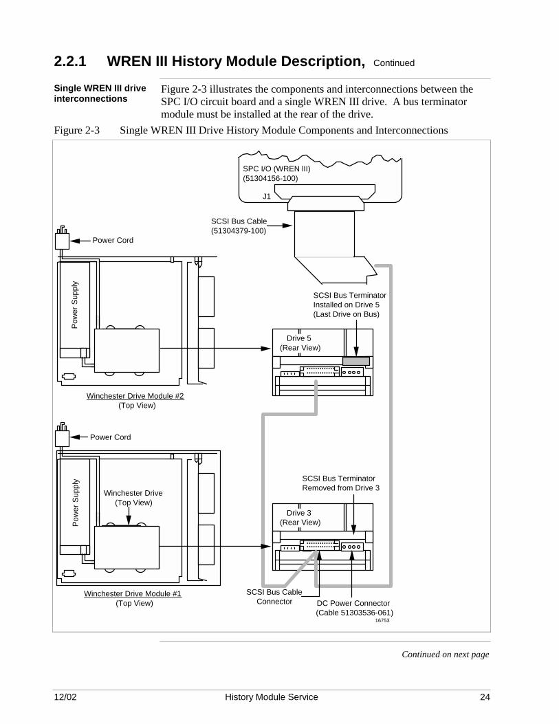
Single WREN III drive interconnections
Figure 2-3 illustrates the components and interconnections between the SPC I/O circuit board and a single WREN III drive. A bus terminator module must be installed at the rear of the drive.
Figure 2-3 Single WREN III Drive History Module Components and Interconnections
16753
SPC I/O (WREN lII) (51304156-100)
J1
Winchester Drive Module #1 (Top View)
Power Cord
SCSI Bus Cable (51304379-100)
SCSI Bus Cable Connector DC Power Connector
(Cable 51303536-061)
SCSI Bus Terminator Installed on Drive 5 (Last Drive on Bus)
Pow
er S
uppl
y
Power Cord
Drive 3 (Rear View)
..........................
Drive 5 (Rear View)
..........................
Winchester Drive Module #2 (Top View)
Winchester Drive (Top View)
SCSI Bus Terminator Removed from Drive 3
Pow
er S
uppl
y
Continued on next page

12/02 History Module Service 25
2.2.1 WREN III History Module Description, Continued
Dual WREN III drive configuration
In a WREN III History Module with dual drives, the drive mounted in the bottom Winchester Drive Module (module #1) is designated “Drive 3” and must be pinned for SCSI bus address 3. It is referred to as “Device 3.” The drive that is mounted in the top Winchester Drive Module (module #2) is designated “Drive 5” and must be pinned for SCSI bus address 5. It is referred to as “Device 5.” Figure 2-2 illustrates the drive positions and address assignments of the drives on the tray assemblies. It is a conventional practice to have Device 3 in the lower Winchester module and Device 5 in the upper Winchester module. Electrically, it is possible for their locations to be reversed. However, to avoid confusion, the standard configuration is recommended. Figure 2-4 illustrates the components and interconnections between the SPC I/O circuit board and the dual WREN III drives. A bus terminator module must be installed on the drive that is at the end of the SCSI bus ribbon cable (Drive 5, Device 5). A drive that is in the middle of the SCSI bus (Drive 3, Device 3) must not have a bus terminator module installed on it. It may appear excessive that a separate Winchester Drive Module (with power supply) is used to house each WREN III drive when a second drive can be accommodated in a single Winchester Drive Module. If data is being written to a WREN III drive at the same instant that AC power fails, there must be a way to provide power to the drive until it has had time to complete the write cycle and avoid corrupted data. The Winchester disk drive power supply is designed with sufficient “ride through power” to sustain power for a single WREN III drive, but not enough capability for two drives. For this reason, a single power supply is allocated for each WREN III drive that must record unduplicated data.
Continued on next page

12/02 History Module Service 26
2.2.1 WREN III History Module Description, Continued
Dual WREN III drive interconnections
Figure 2-4 Dual WREN III Drive History Module Components and Interconnections
16753
SPC I/O (WREN lII) (51304156-100)
J1
Winchester Drive Module #1 (Top View)
Power Cord
SCSI Bus Cable (51304379-100)
SCSI Bus Cable Connector DC Power Connector
(Cable 51303536-061)
SCSI Bus Terminator Installed on Drive 5 (Last Drive on Bus)
Pow
er S
uppl
y
Power Cord
Drive 3 (Rear View)
..........................
Drive 5 (Rear View)
..........................
Winchester Drive Module #2 (Top View)
Winchester Drive (Top View)
SCSI Bus Terminator Removed from Drive 3
Pow
er S
uppl
y

12/02 History Module Service 27
2.2.2 210/445/875 MB and 1.8 GB History Module Description
Overview Figure 2-5 illustrates a WREN type History Module that has been upgraded to accommodate dual 210 megabyte, 445 megabyte, 875 megabyte, or 1.8 gigabyte Winchester disk drives. The drive(s) in a WREN I, WREN II, or WREN III History Module can be replaced with the 210, 445, or 875 MB drive. The following replacement kits are available. • 210 MB drive replacement kit – part number 51196269-100 • 445 MB drive replacement kit – part number 51196351-100 • 875 MB drive replacement kit – part number 51196720-100 • 1.8 GB drive replacement kit – part number 51196897-100 A kit contains one drive, installation hardware, and installation instructions. The electronics module can be the standard LCN Five-Slot Module or Dual Node Module. Figure 2-5 illustrates the Five-Slot Module. Each of the two Winchester Drive Modules occupy the same space as a Five-Slot Module or Dual Node Module, but they contain a slide-out tray assembly on which a 210 MB, 445 MB, 875 MB, or 1.8 GB drive is mounted. Each Winchester Drive Module has its own power supply that is mounted at the left side of the tray assembly. Figure 2-5 Dual 210/445/875 MB or 1.8 GB Drive History Module (Five-Slot Module)
UD
LD
Continued on next page
12/02 History Module Service 28
2.2.2 210/445/875 MB and 1.8 GB History Module Description, Continued
Hardware configurations
The 210 MB, 445 MB, 875 MB, or 1.8 GB drive is easily identified by its small size, with the size of the disk only 3 1/2 inches. An adapter plate is used to adapt the drive directly to the mounting holes on the tray assembly that are normally used for the WREN III drive. No shock-mounts are used. The Winchester Drive Modules and the electronics module are always mounted one above the other as illustrated in the Figure 2-5. A single SCSI bus ribbon cable from the SPC I/O circuit board in the I/O cage at the rear of the electronics module enters a slot at the rear of the lower Winchester Drive Module, routes over the slide tray assembly, and connects to the drive(s) on the tray assembly. The cable then exits the module and enters the upper Winchester Drive Module where it connects to the drive(s) on the tray assembly. In the standard nonredundant configurations, the SCSI (Small Computer Systems Interface—often nicknamed “scuzzy”) bus cable interconnects to one or two drives. The end drive on the interface has termination resistor modules installed on it. The SCSI bus ribbon cable is a group of transmission lines that must be terminated at each end, on the SPC I/O circuit board, and at the drive end of the SCSI bus cable. The actual routing of the SCSI bus ribbon cable is illustrated elsewhere in this manual. If the drives are installed in a nonredundant History Module, three SCSI bus termination resistor modules are located on the last drive on the cable. When drives are installed in a redundant History Module, a bus terminator card provides the termination at the physical end of the SCSI bus ribbon cable, separate from the last drive on the bus. The bus terminator card is fastened to the top of the upper Winchester Drive Module chassis. This arrangement permits a failed drive to be disconnected while power is applied and not disturb its redundant partner on the same SCSI bus.
Continued on next page

12/02 History Module Service 29
2.2.2 210/445/875 MB and 1.8 GB History Module Description, Continued
Electronics module configuration
The functional board complement of the electronics module varies for different software releases. See the Five/Ten-Slot Module Service or Dual Node Module Service manual for the board complement that matches your original hardware. The Smart Peripheral Controller (SPC) circuit board and its associated SPC I/O circuit board are used to communicate with the drives. For other current board types, refer to the Five/Ten-Slot Module Service or Dual Node Module Service manual. This is an LCN module using standard LCN cabling. See the Five/Ten-Slot Module Service or Dual Node Module Service manual for LCN cabling information.
Drive configurations The drive mounted in the Winchester Drive Module is designated “Drive
5,” referred to as as “Device 5,” and must be pinned (configured) for address 5. When you have a single drive History Module, this is the only drive. The drive is always assigned address 5 and is mounted in a single Winchester Drive Module. Figure 2-6 illustrates the drive position and address assignment of the drive on the tray assembly. Figure 2-6 210/445/875 MB or 1.8 GB Drive Positioning and Address Assignments
16751Single Drive History Module Dual Drive History Module
Drive 3 Address = 3
Drive 5 Address = 5
Drive 5 Address = 5
Continued on next page

12/02 History Module Service 30
2.2.2 210/445/875 MB and 1.8 GB History Module Description, Continued
Single drive configuration
Figure 2-7 illustrates the components and interconnections between the SPC I/O circuit board and a single drive. Three SCSI bus termination resistor modules must be installed on the bottom of the 210 MB or 445 MB drive.
Figure 2-7 Single 210/445/875 MB or 1.8 GB Drive History Module Components and Interconnections
+ +
5-Slot Module (HM)
Rear View
WDC(51400668)
+ +
Fan
SPC (51401052-100)
LCN (51400667-100)HMPU (51400978-100) 1
2
5
Power Supply
SPC I/O (51304156-100)
J1
LCN A
LCN I/O (51107403-100)
J1J2
LCN B
51190728-10551190728-105
Drive Power Supply
Power Cord
Winchester Drive Chassis (Top View)
DC Power Cable (51303536-061)
12345SPC I/O
LCN I/O
Front View (Front Panel Omitted)
SCSI Bus Ribbon Cable (51304191-100)
Drive 5 (Rear View)................................ ................
Fan Assembly
5-Slot Module (HM)
Fan Assembly Cable (51303549-100)
Red Line
Note: Depending upon the manufacturing date of the History Module, an EMPU, HMPU, or HPK2 could be installed in slot 1. If an HPK2 is installed in slot 1, the SPC and SPC I/O circuit boards must be installed in slot 4 because no more than than two empty slots can exist between circuit boards. 16780
Continued on next page

12/02 History Module Service 31
2.2.2 210/445/875 MB and 1.8 GB History Module Description, Continued
Dual drive configuration
In a History Module with dual drives, the drive mounted in the front position in the bottom Winchester Drive Module (module #1) is designated “Drive 3” and must be pinned for SCSI bus address 3. It is referred to as “Device 3.” The drive that is mounted in the top Winchester module (module #2) is designated “Drive 5,” pinned for address 5, and referred to as “Device 5.” Figure 2-8 illustrates the positions and addresses of the drives on the tray assemblies. Figure 2-8 illustrates the components and interconnections between the SPC I/O circuit board and the dual drives. Three SCSI bus termination resistor modules must be installed on the bottom of the drive that is at the end of the SCSI bus ribbon cable (Device 5). The drive that is located in the middle of the SCSI bus (Device 3) must have no SCSI bus termination resistor modules installed on it. It may appear excessive that a separate Winchester Drive Module (with power supply) is used to house each drive when a second drive can be accommodated in a single Winchester Drive Module. If data is being written to a drive at the same instant that AC power fails, there must be a way to provide power to the drive until it has had time to complete the write cycle and avoid corrupted data. The Winchester Disk Drive power supply is designed with sufficient “ride through power” to sustain power for a single drive, but not enough capability for two drives. For this reason, a single power supply is allocated for each drive that must record unduplicated data.
Continued on next page

12/02 History Module Service 32
2.2.2 210/445/875 MB and 1.8 GB History Module Description, Continued
Dual drive interconnections
Figure 2-8 Dual Drive HM Components and Interconnections
+ +
5-Slot Module (HM)
Rear View
WDC(51400668)
+ +
Fan
SPC (51401052-100)
LCN (51400667-100)HMPU (51400978-100) 1
2
5
Power Supply
SPC I/O (51304156-100)
J1
LCN A
LCN I/O (51107403-100)
J1J2
LCN B
51190728-10551190728-105
Drive Power Supply
Power Cord
Lower Winchester Drive Chassis (Top View) DC Power Cable (51303536-061)
12345SPC I/O
LCN I/O
Front View (Front Panel Omitted)
SCSI Bus Ribbon Cable (51304192-100)
Drive 3 (Rear View)
Fan Assembly
Fan Assembly Cable (51303549-100)
5-Slot Module (HM)
Drive Power SupplyPower Cord
Upper Winchester Drive Chassis (Top View) DC Power Cable (51303536-061)
Drive 5 (Rear View)
Fan Assembly
Fan Assembly Cable (51303549-100)
••••••••••••••••••••••••••••••••••••••••••••••••••••••••
••••••••••••••••••••••••••••••••••••••••••••••••••••••••
Red Line
Note: Depending upon the manufacturing date of the History Module, an EMPU, HMPU, or HPK2 could be installed in slot 1. If an HPK2 is installed in slot 1, the SPC and SPC I/O circuit boards must be installed in slot 4 because no more than two empty slots can exist between circuit boards. 12864

12/02 History Module Service 33
2.3 Redundant Drive History Modules
Overview History Modules are capable of redundant disk drive configurations. The
additional redundant Winchester disk drive(s) is located in a second Winchester Drive Module that is stacked above the primary Winchester Drive Module and is physically similar to the WREN III, 210 MB, 445 MB, 875 MB, or 1.8 GB Dual Drive configuration that is illustrated in Figures 2-1 and 2-5.
What is redundancy? The term “redundancy” is used to describe redundant WREN III, 210 MB,
445 MB, 875 MB, or 1.8 GB drives, not redundant electronics modules, which is the case with other LCN modules. Although hard drives are quite reliable, the catastrophic nature by which data is lost during a failure indicates a possible need for data to be backed-up during normal operation.
Redundancy drive synchronization
In a redundant configuration, software does a successful write to one WREN III, 210 MB, 445 MB, 875 MB. or 1.8 GB drive, then does an identical write to its redundant partner to provide two drives with identical databases. The process is called “data synchronization.” If a hard drive “crash” occurs, software ignores the failed drive and continues to operate with its good partner. The redundant hardware is designed so that a maintenance technician can remove the failed drive without disturbing or removing power from its good partner. After the drive has been replaced, the technician performs a “synchronization” task that copies the data to the new drive and restores redundant operation.
Drive maintenancewith redundancy
Redundancy is designed into the hardware so that a service technician can remove the Winchester Drive Tray that contains the failed drive without disturbing or removing power from its “good” partner mounted on another tray. After the defective drive has been repaired or replaced, the tray is reinstalled, and the technician performs a “data synchronization” procedure that copies the data stored on the “good” (backup) drive to the repaired or replaced drive. Redundancy operation is then restored. To recover from an unrecoverable data error on a drive, bad sectors can be initialized or assigned to the Defect Data List while system operation continues using the “good” drive.
Continued on next page
12/02 History Module Service 34
2.3 Redundant Drive History Modules, Continued
Redundant physical configurations
The Winchester Drive Modules and the electronics modules are always mounted one above the other, as illustrated in Figures 2-1 and 2-5. A single SCSI bus ribbon cable from the SPC I/O card in the card cage at the rear of the electronics module enters a slot at the rear of the lower Winchester Drive Module, routes over the slide-out tray assembly, and connects to the drive(s) on the tray assembly. The cable then exits the module and enters the upper Winchester Drive Module where it connects to the drive(s) on its tray assembly. In redundant configurations, this SCSI (Small Computer Systems Interface—often nicknamed “scuzzy”) bus cable interconnects up to four drives in a continuous string before ending at a bus terminator card in the upper Winchester Drive Module. The SCSI bus ribbon cable is a group of transmission lines and must be terminated at each end. The bus is terminated on the SPC I/O circuit board and also at the drive end of the SCSI bus cable. The actual routing of the SCSI bus cable is illustrated elsewhere in this manual. Since a SCSI bus terminator card is located at the physical end of the SCSI bus ribbon cable where it is fastened to the top of the upper Winchester Drive Module (module #2), there are no bus terminators installed on the drives. This arrangement permits a failed drive to be removed and replaced without disturbing power to its redundant partner on the same SCSI bus.
Redundant electronics module configuration
A Smart Peripheral Controller (SPC) circuit board and its associated SPC I/O card are used to communicate with the drives. The other board types in the electronics module can vary with the type of LCN module, Five-Slot Module or Dual Node Module, and can be a function of the software release. For board configuration information, refer to the Five/Ten-Slot Module Service or Dual Node Module Service manual. This is an LCN module using standard LCN cabling. See the Five/Ten-Slot Module Service or Dual Node Module Service manual for LCN cabling information.
ATTENTION ATTENTION—History Modules with redundant disk drive configurations do not include redundant electronics modules. History Modules are not available with redundant electronics.

12/02 History Module Service 35
2.3.1 Redundant Single Disk Drive Configuration
Overview A History Module with redundant single drives is physically similar to a
History Module with nonredundant dual drives as illustrated in Figures 2-1 and 2-5. The only physical difference is the presence of a bus terminator card that is mounted underneath the top surface of the upper Winchester Drive Module (module #2).
Drive pinning The drive mounted in the top Winchester Drive Module (module #2) is
designated “Drive 5” and must be pinned for address 5. It is referred to as “Device 5.” Its redundant partner that is mounted in the bottom Winchester Drive Module (module #1) is designated “Drive 4” and must be pinned for address 4. It is referred to as “Device 4.” Figure 2-9 illustrates the positions and address assignments of the drives on the tray assemblies, while Figures 2-10 and 2-11 illustrate the components and interconnections of a History Module with a redundant single drives. Figure 2-9 Redundant Drive Physical Locations and Addresses
Redundant Single Drives Redundant Dual Drives
Drive 5 Address = 5
Drive 4 Address = 4
Drive 3 Address = 3
Drive 4 Address = 4
Drive 2 Address = 2
Drive 5 Address = 5
16754
Continued on next page

12/02 History Module Service 36
2.3.1 Redundant Single Drive Configuration, Continued
Redundant single WREN III drive interconnections
Figure 2-10 Redundant Single WREN III Drive Components and Interconnections
16755
SPC I/O (WREN lII) (51304156-100)
J1
Power Cord
SCSI Bus Cable (51304193-100)
SCSI Bus Cable Connector DC Power Connector
(Cable 51303536-061)
Pow
er S
uppl
y
Power Cord
Drive 4 (Rear View)
..........................
Drive 5 (Rear View)
..........................
Winchester Drive (Top View)
SCSI Bus Terminators Removed from Both Drives
Winchester Drive Module #1 (Top View)
Winchester Drive Module #2 (Top View)
SCSI Bus Terminator Assembly (51195178-100), Located in Drive Module #2, and Connected at End of Bus
Pow
er S
uppl
y

12/02 History Module Service 37
2.3.1 Redundant Single Drive Configuration, Continued
Redundant single drive interconnections
Figure 2-11 Redundant Single 210/445/875 MB or 1.8 GB Drive Components and Interconnections
+ +
5-Slot Module (HM)
Rear View
WDC(51400668)
+ +
Fan
SPC (51401052-100)
LCN (51400667-100)HMPU (51400978-100) 1
2
5
Power Supply
SPC I/O (51304156-100)
J1
LCN A
LCN I/O (51107403-100)
J1J2
LCN B
51190728-10551190728-105
Drive Power Supply
Power Cord
Lower Winchester Drive Chassis (Top View) DC Power Cable (51303536-061)
12345SPC I/O
LCN I/O
Front View (Front Panel Omitted)
SCSI Bus Ribbon Cable (51304193-100)
Drive 4 (Rear View)
Fan Assembly
Fan Assembly Cable (51303549-100)
5-Slot Module (HM)
Drive Power SupplyPower Cord
Upper Winchester Drive Chassis (Top View) DC Power Cable (51303536-061)
Drive 5 (Rear View)
Fan Assembly
Fan Assembly Cable (51303549-100)
••••••••••••••••••••••••••••••••••••••••••••••••••••••••
••••••••••••••••••••••••••••••••••••••••••••••••••••••••Terminator Board (51195180-100)
Red Line
Note: Depending upon the manufacturing date of the History Module, an EMPU, HMPU, or HPK2 could be installed in slot 1. If an HPK2 is installed in slot 1, the SPC and SPC I/O circuit boards must be installed in slot 4 because no more than than two empty slots can exist between circuit boards. 11853

12/02 History Module Service 38
2.3.2 Redundant Dual Drive Configuration
Overview A History Module with redundant dual drives is physically similar to a
History Module with a redundant single drive that is discussed in subsection 2.3.1, but each of the Winchester Drive Module has two WREN III, 210 MB, 445 MB, 875 MB, or 1.8 GB drives mounted on its slide-out tray assembly as illustrated in Figure 2-9.
Drive pinning The top Winchester Drive Module (module #2) contains Drive 5 (Device
5), pinned for address 5, and Drive 3 (Device 3), pinned for address 3. The bottom Winchester Drive Module (module #1) contains Drive 4 (Device 4), pinned for address 4, and Drive 2 (Device 2), pinned for address 2. Figure 2-9 illustrates the positions and address assignments of the drives on the tray assemblies, while Figures 2-12 and 2-13 illustrates the components and interconnections of the drives. In subsections 2.2.1 and 2.2.2, it is stated that only one drive should be mounted in a Winchester Drive Module. The redundant dual drive configuration seems to contradict that statement. In a redundant dual drive configuration, there is a remote possibility that data being written to a drive might be corrupted by a power failure, but it would occur in only one drive, and not in the redundant partner also. When power eventually returns, the software will sense the error while synchronizing the redundant data files and will overwrite the corrupted data.
Continued on next page

12/02 History Module Service 39
2.3.2 Redundant Dual Drive Configuration, Continued
Redundant dual WREN III drive interconnections
Figure 2-12 Redundant Dual WREN III Drive Components and Interconnections
16756
SPC I/O (WREN lII) (51304156-100)
J1
Winchester Drive Module #1 (Top View)
Power Cord
SCSI Bus Cable (51304194-100)
SCSI Bus Cable Connector DC Power Connector
(Cable 51303536-061)
SCSI Bus Terminator Assembly (51195178-100) Installed at End of Bus in Drive Module #2
Pow
er S
uppl
y
Power Cord
Drive 4 (Rear View)
..........................
Drive 2 (Rear View)
..........................
Drive 5 (Rear View)
..........................
Drive 3 (Rear View)
..........................
Winchester Drive Module #2 (Top View)
Winchester Drive (Top View)
Note: SCSI Bus Terminators must be removed from all drives.
Pow
er S
uppl
y

12/02 History Module Service 40
2.3.2 Redundant Dual Drive Configuration, Continued
Redundant dual 210/445/875 MB or | 1.8 GB drive interconnections
Figure 2-13 Redundant Dual 210/445/875 MB or 1.8 GB Drive Components and Interconnections
+ +
5-Slot Module (HM)
Rear View
WDC(51400668)
+ +
Fan
SPC (51401052-100)
LCN (51400667-100)HMPU (51400978-100) 1
2
5
Power Supply
SPC I/O (51304156-100)
J1
LCN A
LCN I/O (51107403-100)J1
J2LCN B
51190728-10551190728-105
Drive Power Supply
Power Cord
Lower Winchester Drive Chassis (Top View) DC Power Cable (51303536-061)
12345SPC I/O
LCN I/O
Front View (Front Panel Omitted)
SCSI Bus Ribbon Cable (51304194-100)
Drive 4 (Rear View)
Fan Assembly
Fan Assembly Cable (51303549-100)
5-Slot Module (HM)
Drive Power SupplyPower Cord
Upper Winchester Drive Chassis (Top View) DC Power Cable (51303536-061)
Drive 5 (Rear View)
Fan Assembly
Fan Assembly Cable (51303549-100)
Drive 2 (Rear View)
Drive 3 (Rear View)
••••••••••••••••••••••••••••••••••••••••••••••••••••••••
••••••••••••••••••••••••••••••••••••••••••••••••••••••••
••••••••••••••••••••••••••••••••••••••••••••••••••••••••
••••••••••••••••••••••••••••••••••••••••••••••••••••••••
Terminator Board (51195178-100)
Red Line
Note: Depending upon the manufacturing date of the History Module, an EMPU, HMPU, or HPK2 could be installed in slot 1. If an HPK2 is installed in slot 1, the SPC and SPC I/O circuit boards must be installedslot 4 because no more than than two empty slots can exist between circuit boards.
11859

12/02 History Module Service 41
Section 3 – WDA Type History Module with Type I Drive
3.1 Overview
Section contents The topics covered in this section are:
Topic See Page 3.1 Overview 43 3.2 Description 45 3.3 Physical Configuration 49 3.4 Circuit Board Configuration 51 3.5 Nonredundant Drive History Module Configuration 52 3.5.1 Single Disk Drive Configuration 52 3.5.2 Dual Disk Drives Configuration 54 3.6 Redundant Drives History Module Configuration 56 3.6.1 Single Disk Drive Configuration 57 3.6.2 Dual Disk Drives Configuration 59 3.7 Field Adjustments 61
Purpose of the section
This section describes the four possible configurations for the WDA Type I History Module hardware, including hardware servicing and replacement. TYPE II drive trays are described in Section 4 4.
Purpose of the WDA type History Module
The WDA type History Module (HM) provides mass data storage for history files, system software, and customer files for the TPS system. The WDA History Module is a node on the Local Control Network (LCN) with a specific address assigned. More than one WDA History Module can reside on the network. Figure 3-1 Single-Drive TYPE I Winchester Drive Tray
6769
1
5
47
8 6
3
Continued on next page

12/02 History Module Service 42
3.1 Overview, Continued
WDA type History Module overview
The WDA History Module consists of the electronics necessary to interface to the LCN, and the electronics necessary to control one, two, or four 3.5-inch Winchester hard disk drives. The WDA History Module is packaged in a Five-Slot Module chassis.
How to use this section
Use this section to identify the History Module parts and understand the operation of the WDA History Module. Then, concentrate on the sections in the manual that meet your needs, such as testing/troubleshooting, disassembly, assembly, servicing, and History Module startup.
Redundant drive configuration
The physical configuration of the WDA History Module can contain nonredundant or redundant drives. When configured for redundant drives, data is written to the redundant drives almost simultaneously. If one of the drives should fail, the redundant partner has the full database intact and can continue to provide normal operation capability until the failed drive is repaired or replaced. For more information on redundant drives, go to subsection 3.6. Figure 3-2 Dual-Drive TYPE I Winchester Drive Tray
6768
1
2
3
47
8 6
Field Adjustments There are no field adjustments required for the WDA History Module’s
electronics or Winchester disk drives.

12/02 History Module Service 43
3.2 Description
CE Compliance The design of the Five-Slot Module chassis and the I/O circuit boards that
install in the rear card cage has changed for CE Compliance. Pertinent information can be found in the Five/Ten-Slot Service manual. Functionally, the non-CE Compliant and CE Compliant WDA History Modules are the same. However, the I/O circuit boards that install in the rear card cages are not interchangeable because of their physical characteristics.
Overview Figures 3-3 and 3-4 illustrate the front and rear views of the non-CE
Compliant and CE Compliant WDA History Modules that can be configured for one, two, or four Winchester disk drives. The non-CE Compliant module illustrated is the enhanced LCN Five-Slot Module. Besides circuit boards that control the interface to the Local Control Network (K2LCN or K4LCN) and the drives (SPC), the module also contains two slide-out trays on which the Winchester disk drives are mounted. The trays are installed in a Winchester Disk Assembly (WDA) that occupies circuit board slots 4 and 5 in the module. Only the right-hand tray is present for a nonredundant drive configuration. Both trays are present for a redundant drive configuration. The modules have an enhanced power supply, located at the bottom of the module, that provides power for the circuit boards, the drive(s), and the fan assembly. A fan assembly is located at the right-hand side of the module and provides cooling for the circuit boards, power supply, and the drive(s).
Continued on next page

12/02 History Module Service 44
3.2 Description, Continued
Non-CE Compliant WDA History Module
Figure 3-3 WDA History Module – Non-CE Compliant
FRONT VIEW
REAR VIEW
ON
Fan Assembly
Power Supply
Ribbon Cable
WDI I/O
SPCII I/OLCN I/O
OFFON
OFF
Right-Hand TrayTray Power Switch
Left-Hand Tray
21
3
4
5
SPCK2LCN-2
Reset ButtonNode Power Switch
21
345
6765
Continued on next page

12/02 History Module Service 45
3.2 Description, Continued
Non-CE Compliant WDA History Module
Figure 3-4 WDA History Module – CE Compliant
FRONT VIEW
REAR VIEW
ON
Fan Assembly
Power Supply
Ribbon Cable
WDI
SPC2 CLCN A/B
OFFON
OFF
Right-Hand TrayTray Power Switch
Left-Hand Tray
21
3
4
5
SPCK2LCN/K4LCN
Reset ButtonNode Power Switch
21
345
16758
Continued on next page

12/02 History Module Service 46
3.2 Description, Continued
WDA History Module block diagram
Figure 3-5 is a block diagram of the WDA History Module illustrating the path between the LCN and the Winchester disk drives. A functional description of the enhanced Five-Slot Module chassis that provides the electronics for the WDA History Module hardware can be found in the Five/Ten-Slot Module Service manual. Figure 3-5 WDA History Module Block Diagram
M O D U L E
B U S +5 V
+12 V +24 V HM Fan
Power Supply
K2LCN
SPC
LCN I/OLCN A CoaxLCN B Coax
SPCII I/O
Drive 4*
Drive 2*
Left Tray
Drive 5
Drive 3*
Right Tray
WDI
WDI I/O
Ribbon Cables
* Optional Disk Drives 9457
SCSI
Bus

12/02 History Module Service 47
3.3 Physical Configuration
Winchester disk drives
The Winchester hard disk drives (one, two, or four can be present) are mounted on two Winchester Drive Trays, resident in the Winchester Disk Assembly that occupies the upper two circuit board slots (slots 4 and 5) of the module as illustrated in Figures 3-2 and 3-3.
SCSI bus interconnections
Dual Small Computer Systems Interface, (SCSI) bus ribbon cables connect the Smart Peripheral Controller I/O (SPCII/SPC2) circuit board, located at the rear of the Smart Peripheral Controller (SPC) circuit board (slot 2), to the Winchester Drive Interface I/O (WDI I/O/WDI) circuit board, located at the rear of the Winchester Disk Assembly (slot 5). The Winchester Drive Interface (WDI) circuit board, located in the Winchester Disk Assembly (WDA), extends the SCSI bus through two printed flex-circuits to the Winchester disk drive(s) mounted on the Winchester Drive Tray(s) as illustrated in Figure 3-5. The bus “splits” on the WDI I/O circuit board, providing the bus interface to each Winchester Drive Tray. The Smart Peripheral Controller (SPC) circuit board interconnects by the SCSI bus ribbon cable and printed flex-circuit with one or two drives on each tray present. The SCSI bus is terminated by termination modules installed on the last (end) drive.
SCSI bus termination When a tray has one Winchester disk drive mounted on it, the drive is
mounted in the front position and must have three bus termination modules installed on the drive if it is a 210 megabyte or 445 megabyte drive. The 875 megabyte and 1.8 gigabyte drives do not have bus termination modules. Instead, internal bus terminators are enabled electronically on the drive by jumper block selection. If a second Winchester disk drive is present on the tray, the second drive is mounted in the rear position on the tray without SCSI bus termination modules installed on it as illustrated in Figure 3-5. The WDI circuit board, resident in the Winchester Disk Assembly, has two sets of SCSI bus resistor terminators, one set for each tray. The set of terminators is activated when power is removed from the individual Winchester Drive Tray by a power switch at the front of the tray. This arrangement allows a failed drive on a tray to be removed and replaced without disturbing its redundant partner that is mounted on another tray, interfacing the same SCSI bus.
Continued on next page

12/02 History Module Service 48
3.3 Physical Configuration, Continued
SCSI bus The SCSI bus ribbon cables and printed flex-circuits are a group of
transmission lines and must be resistor terminated at each end of the SCSI bus. The SPC circuit board contains no bus terminators since it is central to the bus. Figure 3-6 illustrates the routing of the SCSI bus when both Winchester Drive Trays are present and both trays contain dual drives. Figure 3-6 SCSI Bus and Termination Interconnections
Winchester Drive Interface (WDI) Board
WDI I/O Board
Backplane Connector
SPCII I/O Board
Special Peripheral Controller (SPC) Board
Backplane Connector
Slot 2 (Front)
Slot 2 (Rear)
Slot 5 (Rear)
SCSI Bus Ribbon Cable
Winchester Disk Assembly
Drive 2
Rear Disk Drive
Drive 4Front Disk
Drive
Bus Terminators
SCSI Bus Printed Flex-Circuit
Left-Hand Winchester Drive Tray
9466
A redundant dual-drive configuration is shown. If a tray has a single drive mounted on it, the drive will always occupy the front position and will either have SCSI bus termination modules installed on it or have internal bus terminators enabled.
Note:
Drive 3
Rear Disk Drive
Drive 5Front Disk
Drive
Bus Terminators
SCSI Bus Printed Flex-Circuit
Right-Hand Winchester Drive Tray
Slot 5 (Front)
12/02 History Module Service 49
3.4 Circuit Board Configuration
SPC circuit board The Smart Peripheral Controller (SPC) circuit board provides
communication with, and control of, the Winchester disk drives and the SPC I/O circuit board.
WDI and WDI I/O circuit boards
The SPC I/O circuit board and the Winchester Drive Interface (WDI) circuit board in the Winchester Disk Assembly with its associated WDI I/O circuit board provide the SCSI bus interface between the SPC circuit board and the Winchester disk drives. SCSI bus terminators are activated when a Winchester Drive Tray is not present in the WDA or has power removed from it by its power switch. Any Winchester Drive Tray that does not have power applied to it must be removed from the WDA.
K2LCN or K4LCN and LCN I/O circuit boards
The K2LCN or K4LCN circuit board and its associated LCN I/O (CLCN A/B) circuit board provide the electronic link between the Local Control Network (LCN) and the SPC circuit board. The K2LCN and K4LCN circuit board contain the node processor and supporting memory.
Circuit board configuration information
For K2LCN, K4LCN, and LCN I/O (CLCN A/B) circuit board configuration information, refer to the Five/Ten-Slot Module Service manual as well as subsection 8.2.4 in this manual. Configuration of the SPC circuit board is also covered in subsection 8.2.4.

12/02 History Module Service 50
3.5 Nonredundant Drive History Module Configurations
Overview The History Module can be configured for either nonredundant or
redundant drive operation. When configured nonredundant, the Winchester Disk Assembly (WDA) will contain a single Winchester Drive Tray, located at the right-hand side of the assembly. One (single) or two (dual) drives will be mounted on the tray.
3.5.1 Single Disk Drive Configuration
Overview In a nonredundant single-drive WDA History Module, a single drive is
pinned (configured) and labeled as device 5 (SCSI bus address 5), while mounted in the front position of the right-hand Winchester Drive Tray as illustrated in Figure 3-7. Pinning of the drive is shown in Figure 9-6 in subsection 9.4.2. Figure 3-7 Nonredundant Single-Drive Configuration
Nonredundant Dual Drives
Driv
e 5
SCSI Bus Termination Modules
Drive 5
12819
SCSI bus termination modules
Three SCSI bus termination modules must be installed on the bottom of 210 megabyte and 445 megabyte drives as illustrated in Figure 3-6. Internal bus terminators must be enabled on the 875 megabyte and 1.8 gigabyte drives by pinning (configuration). The terminators installed on Drive 5 terminate the SCSI bus on the right-hand tray. The other end of the SCSI bus is terminated by resistors on the WDI circuit board, which are activated when the left-hand Winchester Drive Tray is not present. See subsection 9.4.2 for detailed installation information.
Continued on next page

12/02 History Module Service 51
3.5.1 Single Disk Drive Configuration, Continued
SPC to drive tray interconnections
Figure 3-8 illustrates the components and interconnections between the SPC circuit board and the right-hand (primary) Winchester Drive Tray. The left-hand Winchester Drive Tray is not present. Figure 3-8 Nonredundant Single-Drive Interconnections
Winchester Drive Interface (WDI) Board
WDI I/O Board
Backplane Connector
SPCII I/O Board
Special Peripheral Controller (SPC) Board
Backplane Connector
Slot 2 (Front)
Slot 2 (Rear)
Slot 5 (Rear)
SCSI Bus Ribbon Cable
Winchester Disk Assembly
Left-Hand Tray Not Present
9466.1
Drive 5Front Disk
Drive
Bus Terminators (Primary)
SCSI Bus Printed Flex-Circuit
Right-Hand Winchester Drive Tray
Bus Terminators (Secondary)
Slot 5 (Front)
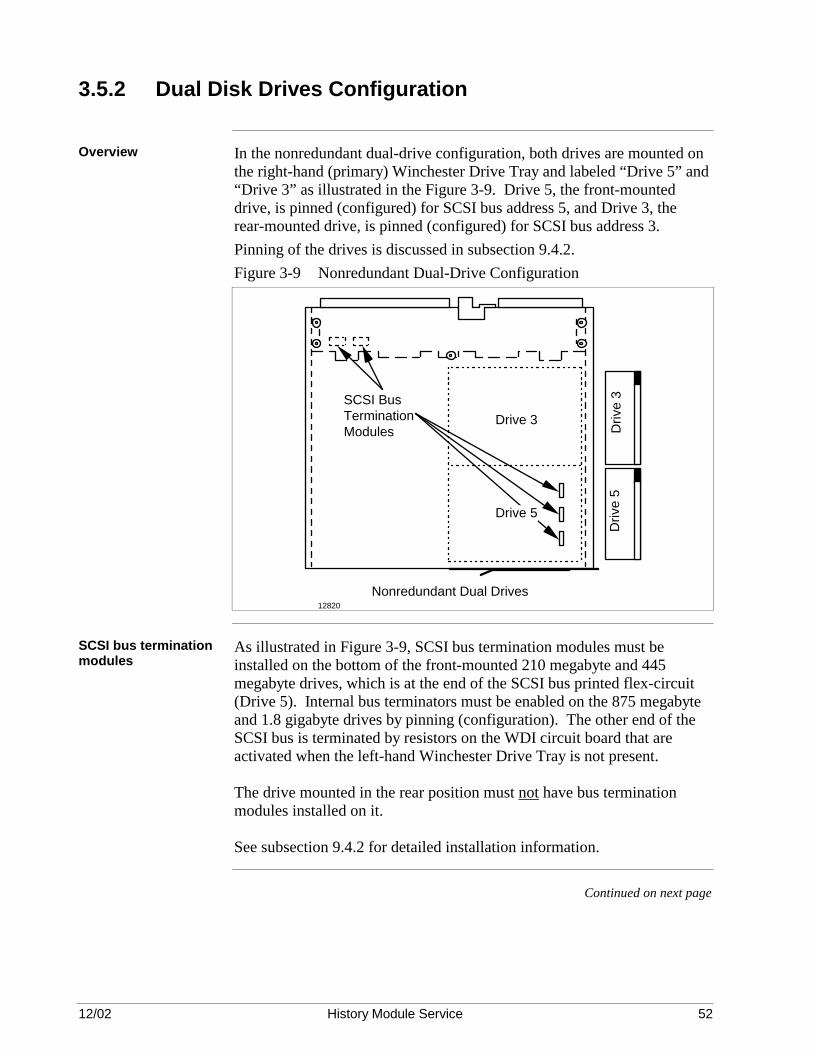
12/02 History Module Service 52
3.5.2 Dual Disk Drives Configuration
Overview In the nonredundant dual-drive configuration, both drives are mounted on
the right-hand (primary) Winchester Drive Tray and labeled “Drive 5” and “Drive 3” as illustrated in the Figure 3-9. Drive 5, the front-mounted drive, is pinned (configured) for SCSI bus address 5, and Drive 3, the rear-mounted drive, is pinned (configured) for SCSI bus address 3. Pinning of the drives is discussed in subsection 9.4.2. Figure 3-9 Nonredundant Dual-Drive Configuration
Drive 3
Nonredundant Dual Drives
Driv
e 5
SCSI Bus Termination Modules D
rive
3
Drive 5
12820
SCSI bus termination modules
As illustrated in Figure 3-9, SCSI bus termination modules must be installed on the bottom of the front-mounted 210 megabyte and 445 megabyte drives, which is at the end of the SCSI bus printed flex-circuit (Drive 5). Internal bus terminators must be enabled on the 875 megabyte and 1.8 gigabyte drives by pinning (configuration). The other end of the SCSI bus is terminated by resistors on the WDI circuit board that are activated when the left-hand Winchester Drive Tray is not present. The drive mounted in the rear position must not have bus termination modules installed on it. See subsection 9.4.2 for detailed installation information.
Continued on next page

12/02 History Module Service 53
3.5.2 Dual Disk Drives Configuration, Continued
SPC to drive tray interconnections
Figure 3-10 illustrates the components and interconnections between the SPC circuit board and the right-hand (primary) Winchester Drive Tray. The left-hand Winchester Drive Tray is not present. Figure 3-10 Nonredundant Dual-Drive Interconnections
Winchester Drive Interface (WDI) Board
WDI I/O Board
Backplane Connector
SPCII I/O Board
Special Peripheral Controller (SPC) Board
Backplane Connector
Slot 2 (Front)
Slot 2 (Rear)
Slot 5 (Rear)
SCSI Bus Ribbon Cable
Winchester Disk Assembly9466.2
Drive 3
Rear Disk Drive
Left-Hand Tray Not Present
Bus Terminators (Secondary)
Drive 5Front Disk
Drive
Bus Terminators (Primary)
SCSI Bus Printed Flex-Circuit
Right-Hand Winchester Drive Tray
Bus Terminators (Secondary)
Slot 5 (Front)

12/02 History Module Service 54
3.6 Redundant Drives History Module Configurations
Overview The History Module is capable of supporting redundant Winchester Disk
drives that are configured as backups for single or dual drives. The additional redundant Winchester Disk drive(s) is mounted on the left-hand (secondary) Winchester Drive Tray that is installed in the Winchester Disk Assembly.
What is redundancy? The term “redundancy” is used to describe redundant Winchester Disk
drives, not redundant History Modules which is how some LCN nodes can be configured. Although hard drives are quite reliable, the catastrophic nature in which data is lost during a failure encourages the need for data to be backed-up during normal operation.
Redundancy drive synchronization
In a redundant configuration, if software does a successful write to one drive, then it will do an identical write to its redundant partner. Therefore, identical data is maintained on two drives in the system. This process is called “data synchronization.” If a drive fails, software ignores the failed drive and continues to operate with the “good” redundant partner. If the failure occurs during a data operation on the primary drive, the operation is completed using the redundant secondary drive. The System Real Time Journal receives an entry identifying the specific sector and volume/file name affected.
Drive maintenancewith redundancy
Redundancy is designed into the hardware so that a service technician can remove the Winchester Drive Tray that contains the failed drive without disturbing or removing power from its “good” partner mounted on another tray. After the defective drive has been repaired or replaced, the tray is reinstalled, and the technician performs a “data synchronization” procedure that copies the data stored on the “good” (backup) drive to the repaired or replaced drive. Redundancy operation is then restored. To recover from an unrecoverable data error on a drive, bad sectors can be initialized or assigned to the Bad Sector List while system operation continues using the “good” drive.
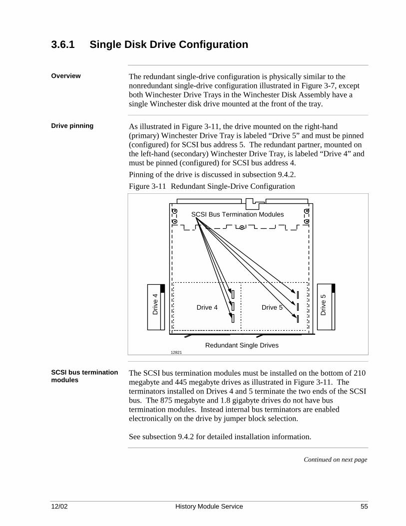
12/02 History Module Service 55
3.6.1 Single Disk Drive Configuration
Overview The redundant single-drive configuration is physically similar to the
nonredundant single-drive configuration illustrated in Figure 3-7, except both Winchester Drive Trays in the Winchester Disk Assembly have a single Winchester disk drive mounted at the front of the tray.
Drive pinning As illustrated in Figure 3-11, the drive mounted on the right-hand
(primary) Winchester Drive Tray is labeled “Drive 5” and must be pinned (configured) for SCSI bus address 5. The redundant partner, mounted on the left-hand (secondary) Winchester Drive Tray, is labeled “Drive 4” and must be pinned (configured) for SCSI bus address 4. Pinning of the drive is discussed in subsection 9.4.2. Figure 3-11 Redundant Single-Drive Configuration
Redundant Single Drives
Drive 5Drive 4
Driv
e 5
Driv
e 4
SCSI Bus Termination Modules
12821
SCSI bus termination modules
The SCSI bus termination modules must be installed on the bottom of 210 megabyte and 445 megabyte drives as illustrated in Figure 3-11. The terminators installed on Drives 4 and 5 terminate the two ends of the SCSI bus. The 875 megabyte and 1.8 gigabyte drives do not have bus termination modules. Instead internal bus terminators are enabled electronically on the drive by jumper block selection. See subsection 9.4.2 for detailed installation information.
Continued on next page

12/02 History Module Service 56
3.6.1 Single Drive Configuration, Continued
SPC to drive tray interconnections
Figure 3-12 illustrates the components and interconnections between the SPC circuit board and both Winchester Drive Trays. Figure 3-12 Redundant Single-Drive History Module Interconnections
Winchester Drive Interface (WDI) Board
WDI I/O Board
Backplane Connector
SPCII I/O Board
Special Peripheral Controller (SPC) Board
Backplane Connector
Slot 2 (Front)
Slot 2 (Rear)
Slot 5 (Rear)
SCSI Bus Ribbon Cable
Winchester Disk Assembly
Drive 4Front Disk
Drive
Bus Terminators (Primary)
SCSI Bus Printed Flex-Circuit
Left-Hand Winchester Drive Tray
9466.3
Drive 5Front Disk
Drive
Bus Terminators (Primary)
SCSI Bus Printed Flex-Circuit
Right-Hand Winchester Drive Tray
Slot 5 (Front)

12/02 History Module Service 57
3.6.2 Dual Disk Drives Configuration
Overview The redundant dual-drive configuration is physically similar to the nonredundant dual-drive configuration illustrated in Figure 3-9, except both Winchester Drive Trays in the Winchester Disk Assembly have dual Type I drives or single Type II drives mounted on the tray.
Mounting and pinning the drives
The drive mounted at the front on the right-hand (primary) Winchester Drive Tray is labeled “Drive 5” in Figure 3-13 and must be pinned (configured) for SCSI bus address 5. The redundant partner, mounted at the front on the left-hand (secondary) Winchester Drive Tray, is labeled “Drive 4” and must be pinned (configured) for SCSI bus address 4. The drive mounted at the rear on the right-hand (primary) Winchester Drive Tray is labeled “Drive 3” in Figure 3-13 and must be pinned (configured) for SCSI bus address 3. The redundant partner, mounted at the rear on the left-hand (secondary) Winchester Drive Tray, is labeled “Drive 2” and must be pinned for SCSI bus address 2. Pinning of the drives is discussed in subsection 11.4.2. Figure 3-13 Redundant Dual-Drive Configuration
Redundant Dual Drives
Drive 3
Drive 4
Driv
e 2
Driv
e 4
SCSI Bus Termination Modules
Drive 2
Drive 5
Driv
e 3
Driv
e 5
12822
SCSI bus termination modules
The SCSI bus termination modules must be installed on the bottom of front 210 megabyte and 445 megabyte drives. The rear drives must not have bus termination modules installed on them. The terminators installed on Drives 4 and 5 terminate the two ends of the SCSI bus. The 875 megabyte and 1.8 gigabyte drives do not have bus termination modules. Instead internal bus terminators are enabled electronically on the drive by jumper block selection. See subsection 11.4.2 for detailed installation information.
Continued on next page

12/02 History Module Service 58
3.6.2 Dual Disk Drives Configuration, Continued
SPC to drive tray interconnections
Figure 3-14 illustrates the components and interconnections between the SPC circuit board and the drives. Figure 3-14 Redundant Dual-Drive History Module Interconnections
Winchester Drive Interface (WDI) Board
WDI I/O Board
Backplane Connector
SPCII I/O Board
Special Peripheral Controller (SPC) Board
Backplane Connector
Slot 2 (Front)
Slot 2 (Rear)
Slot 5 (Rear)
SCSI Bus Ribbon Cable
Winchester Disk Assembly
Drive 2
Rear Disk Drive
Drive 4Front Disk
Drive
Bus Terminators (Primary)
SCSI Bus Printed Flex-Circuit
Left-Hand Winchester Drive Tray
9466.4
Drive 3
Rear Disk Drive
Drive 5Front Disk
Drive
Bus Terminators (Primary)
SCSI Bus Printed Flex-Circuit
Right-Hand Winchester Drive Tray
Slot 5 (Front)

12/02 History Module Service 59
3.7 Field Adjustments
Field Adjustments There are no field adjustments required for the WDA History Module’s
electronics or Winchester disk drives.

12/02 History Module Service 60

12/02 History Module Service 61
Section 4 – WDA History Module With Type II Drive Tray
4.1 Overview
Section contents The topics covered in this section are:
Topic See Page 4.1 Overview 63 4.3 Physical Configuration 69 4.4 Circuit Board Configuration 71 4.5 Nonredundant Drive History Module Configuration 72 4.5.1 Type II Disk DrivesConfiguration 72 4.6 Redundant Drives History Module Configuration 75 4.6.1 Type II Disk Drives Configuration 76 4.7 Field Adjustments 78
Purpose of the section
This section describes the two possible configurations for the WDA type History Module with Type II Drive Tray(s) hardware, including hardware servicing and replacement.
Purpose of the WDA type History Module
The WDA type History Module (HM) provides mass data storage for history files, system software, and customer files for the TPS system. The WDA History Module is a node on the Local Control Network (LCN) with a specific address assigned. More than one WDA History Module can reside on the network. Figure 4-1 Dual-Drive Type II Winchester Drive Tray
6768
1
2
3
47
8 6
Continued on next page

12/02 History Module Service 62
4.1 Overview, Continued
WDA type History Module overview
The WDA History Module consists of the electronics necessary to interface to the LCN, and the electronics necessary to control one or two, 3.5-inch Winchester hard disk drives. The WDA History Module is packaged in a Five-Slot Module chassis.
How to use this section
Use this section to identify the History Module parts and understand the operation of the WDA History Module. Then, concentrate on the sections in the manual that meet your needs, such as testing/troubleshooting, disassembly, assembly, servicing, and History Module startup.
Redundant drive configuration
WDA History Modules can be configured as non-redundant or redundant. When configured for redundant drives, data is written to the redundant drives almost simultaneously. If one of the drives should fail, the redundant partner has the full database intact and can continue to provide normal operation capability until the failed drive is repaired or replaced. For more information on redundant drives, go to subsection 4.6.
Field Adjustments There are no field adjustments required for the WDA History Module’s
electronics or Winchester disk drives.

12/02 History Module Service 63
4.2 Description
CE Compliance The design of the Five-Slot Module chassis and the I/O circuit boards that
install in the rear card cage has changed for CE Compliance. Pertinent information can be found in the Five/Ten-Slot Service manual. Functionally, the non-CE Compliant and CE Compliant WDA History Modules are the same. However, the I/O circuit boards that install in the rear card cages are not interchangeable because of their physical characteristics.
Overview Figures 4-2 and 4-3 illustrate the front and rear views of the non-CE
Compliant and CE Compliant WDA History Modules that can be configured for one oer two Winchester disk drives. The non-CE Compliant module illustrated is the enhanced LCN Five-Slot Module. Besides circuit boards that control the interface to the Local Control Network (K2LCN or K4LCN) and the drives (SPC), the module also contains two slide-out trays on which the Winchester disk drives are mounted. The trays are installed in a Winchester Disk Assembly (WDA) that occupies circuit board slots 4 and 5 in the module. Only the right-hand tray is present for a nonredundant drive configuration. Both trays are present for a redundant drive configuration. The modules have an enhanced power supply, located at the bottom of the module, that provides power for the circuit boards, the drive(s), and the fan assembly. A fan assembly is located at the right-hand side of the module and provides cooling for the circuit boards, power supply, and the drive(s).
Continued on next page

12/02 History Module Service 64
4.2 Description, Continued
Non-CE Compliant WDA History Module
Figure 4-2 WDA History Module – Non-CE Compliant
FRONT VIEW
REAR VIEW
ON
Fan Assembly
Power Supply
Ribbon Cable
WDI I/O
SPCII I/OLCN I/O
OFFON
OFF
Right-Hand TrayTray Power Switch
Left-Hand Tray
21
3
4
5
SPCK2LCN-2
Reset ButtonNode Power Switch
21
345
6765
Continued on next page

12/02 History Module Service 65
4.2 Description, Continued
Non-CE Compliant WDA History Module
Figure 4-3 WDA History Module – CE Compliant
FRONT VIEW
REAR VIEW
ON
Fan Assembly
Power Supply
Ribbon Cable
WDI
SPC2 CLCN A/B
OFFON
OFF
Right-Hand Tray
Tray Power Switch
Left-Hand Tray
21
3
4
5
SPCK2LCN/K4LCN
Reset ButtonNode Power Switch
21
345
16758
Continued on next page

12/02 History Module Service 66
4.2 Description, Continued
WDA History Module block diagram
Figure 4-4 is a block diagram of the WDA History Module illustrating the path between the LCN and the Winchester disk drives. A functional description of the enhanced Five-Slot Module chassis that provides the electronics for the WDA History Module hardware can be found in the Five/Ten-Slot Module Service manual. Figure 4-4 WDA History Module Block Diagram

12/02 History Module Service 67
4.3 Physical Configuration
Winchester disk drives
A Winchester hard disk drive is mounted on each Winchester Drive Tray, resident in the Winchester Disk Assembly that occupies the upper two circuit board slots (slots 4 and 5) of the module as illustrated in Figures 4-2 and 4-3.
SCSI bus interconnections
Dual Small Computer Systems Interface, (SCSI) bus ribbon cables connect the Smart Peripheral Controller I/O (SPCII/SPC2) circuit board, located at the rear of the Smart Peripheral Controller (SPC) circuit board (slot 2), to the Winchester Drive Interface I/O (WDI I/O/WDI) circuit board, located at the rear of the Winchester Disk Assembly (slot 5). The Winchester Disk Interface (WDI) circuit board, located in the Winchester Disk Assembly (WDA), extends the SCSI bus to the Winchester disk drive(s) mounted on the Winchester Drive Tray(s) as illustrated in Figure 4-4. The Smart Peripheral Controller (SPC) circuit board interconnects by the SCSI bus ribbon cable to one drive on each tray present. The SCSI bus is terminated by a termination module installed on the end of the ribbon cable.
SCSI bus termination The SCSI cable (for each tray) is terminated by a terminator mounted on
the end of the SCSI cable that connects to the disk drive. The WDI circuit board, resident in the Winchester Disk Assembly, has two sets of SCSI bus resistor terminators, one set for each end of the bus. The set of terminators is activated when power is removed from the individual Winchester Drive Tray by a power switch at the front of the tray. This arrangement allows a failed drive on a tray to be removed and replaced without disturbing its redundant partner that is mounted on another tray, interfacing the same SCSI bus.
Continued on next page

12/02 History Module Service 68
4.3 Physical Configuration, Continued
SCSI bus The SCSI bus ribbon cables form a group of transmission lines and must
be resistor terminated at each end of the SCSI bus. The SPC circuit board contains no bus terminators since it is central to the bus. Figure 4-5 illustrates the routing of the SCSI bus when both Winchester Drive Trays are present. Figure 4-5 SCSI Bus and Termination Interconnections

12/02 History Module Service 69
4.4 Circuit Board Configuration
SPC circuit board The Smart Peripheral Controller (SPC) circuit board provides
communication with, and control of, the Winchester disk drives and the SPC I/O circuit board.
WDI and WDI I/O circuit boards
The SPC I/O circuit board and the Winchester Drive Interface (WDI) circuit board in the Winchester Disk Assembly with its associated WDI I/O circuit board provide the SCSI bus interface between the SPC circuit board and the Winchester disk drives. SCSI bus terminators are activated when a Winchester Drive Tray is not present in the WDA or has power removed from it by its power switch. Any Winchester Drive Tray that does not have power applied to it must be removed from the WDA.
K2LCN or K4LCN and LCN I/O circuit boards
The K2LCN or K4LCN circuit board and its associated LCN I/O (CLCN A/B) circuit board provide the electronic link between the Local Control Network (LCN) and the SPC circuit board. The K2LCN and K4LCN circuit board contain the node processor and supporting memory.
Circuit board configuration information
For K2LCN, K4LCN, and LCN I/O (CLCN A/B) circuit board configuration information, refer to the Five/Ten-Slot Module Service manual as well as subsection 11.2.4 in this manual. Configuration of the SPC circuit board is also covered in subsection 11.2.4.

12/02 History Module Service 70
4.5 Nonredundant Drive History Module Configurations
Overview The History Module can be configured for either nonredundant or
redundant drive operation. When configured nonredundant, the Winchester Disk Assembly (WDA) will contain a single Winchester Drive Tray, located on the assembly. One (single) drive will be mounted on the tray.
4.5.1 Type II Disk DrivesConfiguration
Overview The Type II disk drive configuration to appears as two drives to system
software even though there is only one physical drive on the tray (i.e. addresses 5 and 3 or 4 and 2). In the nonredundant Type II drive configuration, the drive is mounted on the right-hand (primary) Winchester Drive Tray and labeled “Drive 5” as illustrated in the Figure 4-6. Drive 5, is pinned (configured) for SCSI bus address 5. Pinning of the drives is discussed in subsection 11.4.2. Figure 4-6 Nonredundant Dual-Drive Configuration
12820
Continued on next page
12/02 History Module Service 71
4.5.1 Type II Disk Drives Configuration, Continued
SCSI bus termination modules
The SCSI cable (for each tray) is terminated by a terminator mounted on the end of the SCSI cable. See subsection 11.4.2 for detailed installation information.
Continued on next page

12/02 History Module Service 72
4.5.1 Type II Disk Drives Configuration, Continued
SPC to drive tray interconnections
Figure 4-7 illustrates the components and interconnections between the SPC circuit board and the right-hand (primary) Winchester Drive Tray. The left-hand Winchester Drive Tray is not present. Figure 4-7 Nonredundant Dual-Drive Interconnections

12/02 History Module Service 73
4.6 Redundant Drives History Module Configurations
Overview The History Module is capable of supporting a redundant Winchester Disk
drive that is configured as a backup. The additional redundant Winchester Disk drive is mounted on the left-hand (secondary) Winchester Drive Tray that is installed in the Winchester Disk Assembly.
What is redundancy? The term “redundancy” is used to describe a redundant Winchester Disk
drive, not redundant History Modules. Although hard drives are quite reliable, the catastrophic nature in which data is lost during a failure encourages the need for disk redundancy.
Redundancy drive synchronization
In a redundant configuration, if software does a successful write to one drive, then it will do an identical write to its redundant partner. Therefore, identical data is maintained on two drives in the system. This process is called “data synchronization.” If a drive fails, software ignores the failed drive and continues to operate with the “good” redundant partner. If the failure occurs during a data operation on the primary drive, the operation is completed using the redundant secondary drive. The System Real Time Journal receives an entry identifying the specific sector and volume/file name affected.
Drive maintenancewith redundancy
Redundancy is designed into the hardware so that a service technician can remove the Winchester Drive Tray that contains the failed drive without disturbing or removing power from its “good” partner mounted on another tray. After the defective drive has been repaired or replaced, the tray is reinstalled, and the technician performs a “data synchronization” procedure that copies the data stored on the “good” (backup) drive to the repaired or replaced drive. Redundancy operation is then restored. With the introduction of this drive, bad sector re-assignment will be automatic and will be reported to system software.

12/02 History Module Service 74
4.6.1 Type II Disk Drives Configuration
Overview
Mounting and pinning the drives
The drive mounted on the right-hand (primary) Winchester Drive Tray is labeled “Drive 5” in Figure 4-11 and must be pinned (configured) for SCSI bus address 5. The redundant partner, mounted at the front on the left-hand (secondary) Winchester Drive Tray, is labeled “Drive 4” and must be pinned (configured) for SCSI bus address 4. The drive in Figure 4-8 labeled "Drive 3" is actually the second half of drive 5. The redundant partner, labeled “Drive 2”is actually the second half of Drive 4. Pinning of the drives is discussed in subsection 11.4.2. Figure 4-8 Redundant Dual-Drive Configuration
12822
SCSI bus termination modules
The SCSI cable (for each tray) is terminated by a terminator mounted on the end of the SCSI cable. See subsection 11.4.2 for detailed installation information.
Continued on next page
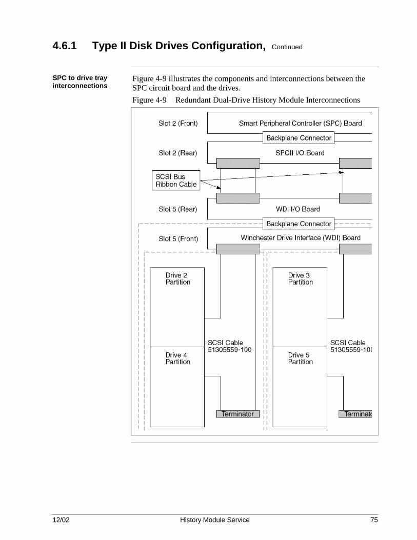
12/02 History Module Service 75
4.6.1 Type II Disk Drives Configuration, Continued
SPC to drive tray interconnections
Figure 4-9 illustrates the components and interconnections between the SPC circuit board and the drives. Figure 4-9 Redundant Dual-Drive History Module Interconnections

12/02 History Module Service 76
4.7 Field Adjustments
Field Adjustments There are no field adjustments required for the WDA History Module’s
electronics or Winchester disk drives.

12/02 History Module Service 77
Section 5 – Test/Troubleshooting 5.1 Overview
Section contents The topics covered in this section are:
Topic See Page
5.1 Overview 79 5.2 Test Strategy 79 5.3 Troubleshooting 82 5.3.1 Preliminary Checks 82 5.3.2 Sequential Troubleshooting 83 5.3.3 Maintenance Recommendations 87 5.3.4 SMCC/Detailed Module Error Messages 89 5.3.5 Real Time Journal (RTJ) Messages 95 5.3.6 Repair Strategy 96 5.3.7 Data Error Recovery Technics and Documentation 98 5.3.8 Nonredundant Drive Data Error Recovery 99 5.3.9 Redundant Drive Data Error Recovery 105 5.3.10 Control Track Error Recovery for Sectors 1-31 108 5.3.11 Status Detail Display 110 5.3.12 Volume Status Display 112 5.3.13 Sector Initialization/Reassignment Procedure 115
Purpose This section analyzes the hardware failure indicators and the software
status displays that are displayed on the Universal Station when a failure occurs. Troubleshooting tactics are presented in response to each failure indicator and status display.
5.2 Test Strategy
CAUTION CAUTION—Read all of the following five considerations before proceeding with the troubleshooting and repair of the History Module.
Consideration 1 DO NOT USE A DISK DRIVE FROM ANOTHER HISTORY
MODULE AS A REPLACEMENT for a drive in a redundant History Module unless you format the replacement drive using the off-line Hardware Verification Test System (HVTS). When a drive contains an existing file system and is used as a replacement, it can corrupt the file system in the redundant History Module in which it is installed. Replacement drives received from the factory will not cause this problem because they are formatted before shipment.
Continued on next page

12/02 History Module Service 78
5.2 Test Strategy, Continued
Consideration 2 DO NOT INITIALIZE A REDUNDANT HISTORY MODULE unless
power is applied to all drives. If power is removed from a redundant drive and the History Module is initialized with a reduced number of volumes available, the existing file system can be corrupted when power is applied to the drive after initialization.
Consideration 3 DO NOT REMOVE POWER FROM THE HISTORY MODULE OR THE DISK DRIVES before you do a node shutdown from the Universal Station. DO THE PRELIMINARY CHECKS in the next subsection before you remove power. When power is removed, you may lose important fault and error information pertinent to the problem.
Consideration 4 DO NOT PRESS THE RESET SWITCH ON THE HISTORY MODULE POWER SUPPLY WHEN A HISTORY MODULE PERSONALITY IS ACTIVE. If a write to a drive is in process, the reset will prevent software from finishing the write and leave corrupted data on the drive. The proper reset procedure is in Table 5.1. Table 5.1 History Module Reset Procedure
Step Action 1 Do a node shutdown from the Universal Station. 2 Remove power from the module with the power supply power switch. 3 Wait 30 seconds, and then reapply power to the History Module. 4 Press the reset button once to abort the normal autoboot, which is
needed only during a History Module initialization procedure.
Consideration 5 When reformatting an 875 megabyte drive (51196680-200) or 1.8 gigabyte
drive (51196895-100), you must use a 11.5 or later release of HVTS.
CAUTION CAUTION—OBSERVE ELECTROSTATIC DISCHARGE (ESD) PROCEDURES. All assemblies used in the History Module contain electrostatically sensitive devices. Use a personnel grounding strap and grounded work surface. Store and transport parts in electrostatically safe containers.
Use a strategy Consider a strategy before attempting the repair of the History Module. How is it used in your system? Is it a system, local, or area History Module? If the data in your system History Module is not used or updated often, you can autoboot it with little impact on the process. The loss of a local History Module containing schematics for the process can be more severe. However, some installations might consider the loss of system data, even for a brief time, critical to the plant’s operation.
Continued on next page

12/02 History Module Service 79
5.2 Test Strategy, Continued
Are there redundant drives?
Does your History Module have redundant drives which allow uninterrupted operation while you service or replace a drive?
Are fast-load cartridges available?
Are fast-load cartridges available to reload critical modules if the History Module is disabled. Refer to the Engineer’s Reference Manual.
Do you have backup copies of the data?
Hopefully, you have made backup copies of your data which must be used if a drive has “crashed” and destroyed data. Also, you must have previously used a special procedure that was discussed in the Engineer’s Reference Manual to backup and restore Continuous History data. If Continuous History Data was saved without using this procedure, the data cannot be properly copied to a replacement drive.
Review the SMCC messages and the RTJ
Review SMCC Maintenance Recommendation messages and the Real Time Journal (RTJ) for clues to the failure. You may need to refer to the Maintenance Test Operations manual, the System Maintenance Guide, and the Hardware Verification Test System (HVTS) manual for reference.
Are there transient or intermittent problems?
The problem can be a transient or intermittent problem. An autoboot can bring the History Module back on-line, or it can delay the recurrence of the problem to a more favorable time. However, remember the autoboot can also destroy some status indicators originally set as a result of a fault. Table 4-2 lists some possible intermittent problems and their correction.
Table 5.2 Troubleshooting Procedure – History Module Operates IntermittentlyIndication Possible Cause Solution
The History Module reports an error, but the reload of the personality software or an autoboot temporarily solves the problem. The problem returns in a day or so.
Open or loose cable. Check out the cable connections on all of the boards and the drives. Inspect the cables for damage. Remove the cables and inspect them for nicks and cuts caused by pinching. Repair or replace damaged cable.
Intermittent board failure. Remove and reseat all the circuit boards. Replace the circuit boards one at a time. If the problem is not corrected after you replace a circuit board, reinstall the original circuit board.
Damaged backpanel or damaged wiring.
Replace the History Module chassis.
Do a “test run” Finally, do a “test run” through the troubleshooting procedures that follow.
You can more accurately estimate how long it will take to correct a problem.
Continued on next page

12/02 History Module Service 80
5.2 Test Strategy, Continued
TAC is available The Honeywell Technical Assistance Center (TAC) engineers can often
help isolate hardware failures and procedural errors. Additionally, they have ready access to Shipping Alerts, Product Release Notices, and problem histories that can help identify the source of a problem. You may wish to call TAC to confirm a diagnosis you have made. You should always call TAC if these troubleshooting procedures cause you to reach a “dead end” or an illogical end result.
5.3 Troubleshooting
Overview The troubleshooting subsection provides an orderly method of diagnosing a problem. Preliminary checks are suggested, followed by sequential troubleshooting procedures. Repair methods are suggested.
5.3.1 Preliminary Checks
Overview Before becoming deeply involved in a problem, perform some preliminary checks. Most of the checks in the steps that follow can be made by observation without removing power from the History Module. Unless an indicator observed in these steps clearly points to a repairable problem, for example, a red LED on the fan assembly, power supply, or a circuit board, leave power applied and go to subsection 5.3.2 where the status errors on displays are interpreted.
Remove the front panel
Remove the front panel of the History Module.
Check the power supply indicators
Check the green LED on the power supply. If it is not lit, place the AC power switch in the OFF position and then back to the ON position. If the green indicator does not illuminate, either the power supply is defective, power is not being provided to it, or there is a output power overload.
Check the fan assembly indicator
If the red LED indicator on the fan assembly is illuminated, the fan assembly is defective. It indicates a lack of air flow.
Check the circuit board indicators
All the green or yellow indicators on the circuit boards must be lit. No red indicators should be lit. The Alphanumeric display on the EMPU/HMPU/HPK2/K2LCN/K4LCN circuit board must illustrate the correct LCN node address. If the status of the indicators is incorrect, go to Table 5.3.

12/02 History Module Service 81
5.3.2 Sequential Troubleshooting
Overview Use the troubleshooting procedure in Figure 5.1 to help isolate a failure. This flowchart assumes the History Module was in an operational state before the error in the flowchart occurred. Attempting an autoboot or loading the node will destroy some status information. The flowchart then refers you to troubleshooting tables and other subsections in this section of the manual.
Figure 5.1 History Module Troubleshooting Flowchart
16761
Start Select SYSTEM STATUS. Check the HISTORY MODULE status.
Is the HM SYSTEM STATUS
OK?
End
Is NODE STATUS
OFF?
Power is off or this node is not connected to the LCN. Correct the problem.
Y
N
N
Y
HM software is performing an interim operation. Wait 1 minute or less and look for a state change.
Is NODE STATUS LOAD, TEST, or
READY?
Has NODE STATUS
changed?
N
Y Check the status of each HM node.
Is NODE STATUS
OK?
Y
N
Y
N
Y
NIs
NODE STATUS FAIL OR
ISOLATED?
If an autoboot was started, it may take up to 15 minutes to complete. Otherwise, the program has "hung." Check the Alphanumeric Display at the front of the K2LCN/K4LCN board. Go to Table 4-4 if it doesn't indicate the proper LCN node number. If it does, reload the HM personality and continue.
The node has failed or become isolated on the LCN. Go to Table 4-3.
Y
NIs
NODE STATUS SEVERE OR WARNING?
An abnormal or critical condition exists. Go to Table 4-5.
NODE STATUS is PWR_ON or
QUALIF?
The History Module software personality is suspect. Go to Table 4-5.
Make sure printer is on. Print out any error message found that follows.
(Once for each HM)
Continued on next page
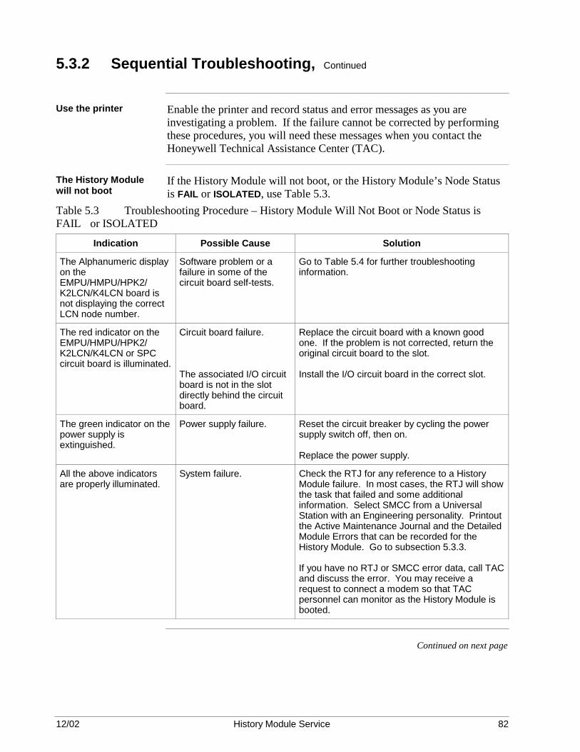
12/02 History Module Service 82
5.3.2 Sequential Troubleshooting, Continued
Use the printer Enable the printer and record status and error messages as you are
investigating a problem. If the failure cannot be corrected by performing these procedures, you will need these messages when you contact the Honeywell Technical Assistance Center (TAC).
The History Module will not boot
If the History Module will not boot, or the History Module’s Node Status is FAIL or ISOLATED, use Table 5.3.
Table 5.3 Troubleshooting Procedure – History Module Will Not Boot or Node Status is FAIL or ISOLATED
Indication Possible Cause Solution
The Alphanumeric display on the EMPU/HMPU/HPK2/ K2LCN/K4LCN board is not displaying the correct LCN node number.
Software problem or a failure in some of the circuit board self-tests.
Go to Table 5.4 for further troubleshooting information.
The red indicator on the EMPU/HMPU/HPK2/ K2LCN/K4LCN or SPC circuit board is illuminated.
Circuit board failure. The associated I/O circuit board is not in the slot directly behind the circuit board.
Replace the circuit board with a known good one. If the problem is not corrected, return the original circuit board to the slot. Install the I/O circuit board in the correct slot.
The green indicator on the power supply is extinguished.
Power supply failure. Reset the circuit breaker by cycling the power supply switch off, then on. Replace the power supply.
All the above indicators are properly illuminated.
System failure. Check the RTJ for any reference to a History Module failure. In most cases, the RTJ will show the task that failed and some additional information. Select SMCC from a Universal Station with an Engineering personality. Printout the Active Maintenance Journal and the Detailed Module Errors that can be recorded for the History Module. Go to subsection 5.3.3. If you have no RTJ or SMCC error data, call TAC and discuss the error. You may receive a request to connect a modem so that TAC personnel can monitor as the History Module is booted.
Continued on next page

12/02 History Module Service 83
5.3.2 Sequential Troubleshooting, Continued
Alphanumeric display is -1xx
If the Alphanumeric display on the EMPU/HMPU/HPK2/K2LCN/K4LCN circuit board shows -1xx, use Table 5.4 to identify the problem.
Table 5.4 Troubleshooting Procedure – Kernel Circuit Board Alphanumeric Display is -1xx
Indication Possible Cause Solution
-190 Power to a Winchester Drive Tray is removed or the power cable to a drive is disconnected.
Be sure all the cables are firmly in place and power is applied to the Winchester Drive Tray(s). Check the SMCC and RTJ journals.
The volume configuration on the system NCF has been altered without the user also initializing the History Module.
Be sure to initialize the History Module after the volume configuration on the system NCF is altered. This is an error in procedure. It is not an equipment failure.
-176 &HMO may not have been copied to the local volume (!9NP).
Review Task 16 in the System Startup Guide. This is an error in procedure. It is not an equipment failure.
A drive is suspect. Call TAC and discuss the problem.
-177 -183 -193 -178 -184 -194 -179 -185 -195 -189
The History Module personality software is corrupted.
Autoboot the History Module. Go to Table 5.3 if the autoboot is not successful. Call TAC if error -189 is repeated.
-188 ($BOOT.MS) -18A (a QLT file) -18C (a personality file) -18E (an OFT file) -18F (bad checksum in any file)
The file is missing, cannot be read, or the copy on the drive is damaged.
Check the contents of the History Module local volume. If the file is missing, damaged, or cannot be read, review Task 16 in System Startup Guide. This is an error in procedure. It is not an equipment failure. Autoboot the History Module. Go to Table 5.3 if not successful. Call TAC if error -18F is repeated.
-1XX (any other number) Circuit board failure. Refer to the Five/Ten-Slot Module Service manual, Appendix A for assistance. Follow the suggestions.
Continued on next page

12/02 History Module Service 84
5.3.2 Sequential Troubleshooting, Continued
History Module Node Status error
If the History Module Node Status has an error displayed, use Table 5.5.
Table 5.5 Troubleshooting Procedure – History Module Node Status Errors
Indication Possible Cause Solution
FAIL or ISOLATED Go to Table 5.3.
WARNING
An abnormal condition exists.
Select the HM STATUS DETAIL target to obtain additional information.
SEVERE
A critical abnormal condition exists.
Select the HM STATUS DETAIL target to obtain additional information.
PWR_ON or QUALIF Note: Each of these states should always be temporary. Do this task only if the state is permanent.
Software corruption.
Autoboot the History Module with the History Module Initialization personality. If the problem is not corrected, transfer a fresh copy of the &HMO and &LDR volumes from removable media to the History Module: CP $Fn>&HMO>*.* PN:nn>!9np>= -D CP $Fn>&LDR>*.*.PN:nn>!9np>= -D then autoboot again. If the above procedure is not successful, go to Table 5.3. Call TAC if the same error is displayed.
12/02 History Module Service 85
5.3.3 Maintenance Recommendations
Overview Maintenance recommendation messages can be found in either the Real
Time Journal (RTJ) or the Active Maintenance Journal. To read the Active Maintenance Journal, select the SMCC/MAINTENANCE target from the Engineering Main Menu. Then select the ACTIVE MAINT JOURNAL target.
Detailed Error Module messages
Some errors will also cause a Detailed Error Module message (also under SMCC) to be generated. Detailed Error Module messages for Winchester disk drives are explained in subsection 5.3.4. If available, use the Detailed Error Module message to confirm other error reports.
Status and Object Detail displays
Check the node's Status Detail display and the Object Detail (Volume Status) displays for error messages and additional status information. Refer to subsections 5.3.11 and 5.3.12. These two types of displays can provide the best detailed information available to assist in an accurate diagnosis.
Check the maintenance messages
If you still have not found your error, compare the RTJ message with the samples in subsection 5.3.5. Also, if you have not already done so, use the printer to make copies of all maintenance messages and System Status Error messages. Then compare them with the types of messages shown in subsections 5.3.3 through 5.3.4, and 5.3.11.
Maintenance message abbreviations
Abbreviations used in these maintenance recommendation messages are:
• np = Node pair • n = Disk drive device number • xxxx = Sector number • mmmm = Volume name
Continued on next page

12/02 History Module Service 86
5.3.3 Maintenance Recommendations, Continued
Maintenance recommendation message examples
Some examples of maintenance recommendation messages can be found in Table 5.6.
Table 5.6 Maintenance Recommendation Messages
Interpretation Action
Message: RUN HVTS FAILED SPC CTLR HM NON RECOV CTLR ERROR
There has been a failure in the SPC controller. The object state is set to FAIL (History Module Node Status).
See Table 5.2.
Message: INVESTIGATE DEGRADED WINCH DISC DRIVE n HM DISK ERROR SECTOR xxxx
There has been a data error either reading or writing drive n. You have lost some of your data.
Check for a Detailed Module Error message. See subsection 5.3.4. Check the Node Status and Status Detail. See subsection 5.3.11. You may be able to reassign the bad sector. Replace the drive if time is valuable and you have a spare. Then plan to reformat this drive and use it for a spare. Go to subsection 5.3.6 and use the information you have learned here. Note: If you have redundant drives, this report is also generated when an error occurs in the synchronization. On-line data is being copied to the off-line drive. DRIVE n in the message signifies which of the redundant drives is faulty. See the special disassembly/assembly procedures for redundant drives. Also, a Status Detail message will be generated giving the volume name, file name, sector address, and error type.
Message: HM np WENT OFLN; NO FUNCTIONS LOST; LOST 1 CTL TRACK Note: The above message is a system status change event, not a maintenance recommendation, as were all the others. At the same time, the following message appears as a maintenance recommendation: RUN HVTS BAD SECTOR WINCH DISC DRIVE n HM DISK ERROR SECTOR xxxx or HM DISK SET OFF LINE (if both control tracks lost)
There has been a Control Track error. Since each drive has two Control Tracks for redundancy, the second Control Track should have kept your data intact and you should still be operational on the second track. You should be able to go back on-line. If both Control Tracks are lost, the drive will be placed off-line and must be replaced. You cannot go back on-line. Neither track has a fixed location on the disk and can possibly be repaired by reassignment or initialization. Use the recovery procedure in either subsection 5.3.8 or 5.3.9.
This is a serious error, but you are probably still operational unless both control tracks were lost. Plan to replace or reformat the disk as soon as your maintenance schedule allows. Check for a Detailed Module Error message in subsection 5.3.4. Check the Node Status and Status Detail in subsection 5.3.11. Go to subsection 5.2.6 and use the information gained here and from the available status indicators.
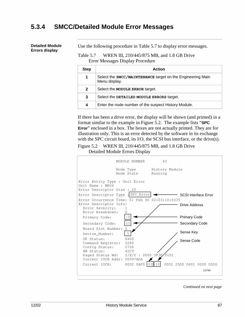
12/02 History Module Service 87
5.3.4 SMCC/Detailed Module Error Messages
Detailed Module Errors display
Use the following procedure in Table 5.7 to display error messages.
Table 5.7 WREN III, 210/445/875 MB, and 1.8 GB Drive Error Messages Display Procedure
Step Action
1 Select the SMCC/MAINTENANCE target on the Engineering Main Menu display.
2 Select the MODULE ERROR target.
3 Select the DETAILED MODULE ERRORS target.
4 Enter the node number of the suspect History Module.
If there has been a drive error, the display will be shown (and printed) in a format similar to the example in Figure 5.2. The example lists “SPC Error” enclosed in a box. The boxes are not actually printed. They are for illustration only. This is an error detected by the software in its exchange with the SPC circuit board, its I/O, the SCSI bus interface, or the drive(s).Figure 5.2 WREN III, 210/445/875 MB, and 1.8 GB Drive Detailed Module Errors Display
MODULE NUMBER 43
Node Type History Module Node State Running
Error Entity Type : Unit ErrorUnit Name : WR04Error Descriptor Size : 20
Error Descriptor Type : SPC Error
Error Occurrence Time: 01 Feb 90 02:03:10:0335Error Descriptor Info: Error Severity: 1 Error Breakdown: 0
Primary Code: -5
Secondary Code: 11
Board Slot Number: 5
Device_Number: 5
OP Status: 8400 Command Register: 0280 Config Status: 0706 HW Status: 42C9 Paged Status Wd: 2/X/Y : 0000 3F3F 0101 Current IOCB Addr: 00097ADA
Current IOCB: 8002 0AF0 03 10 0002 25D0 0601 0000 0000
Sense Key
Sense Code
Primary CodeSecondary Code
Drive Address
SCSI Interface Error
11744
Continued on next page
12/02 History Module Service 88
5.3.4 SMCC/Detailed Module Error Messages, Continued
Identifying the failed drive
The address of the device (drive) is listed in the example Figure 5.2 as “Device_Number 5” or SCSI bus address 5. If there is more than one drive in your system, this is where you can identify the physical drive in which the error occurred.
Determining the cause of the drive failure
To determine the cause of the error, locate the remaining four numbers enclosed in boxes in Figure 5.2. They are labeled Primary Code, Secondary Code, Sense Key, and Sense Code.
Continued on next page

12/02 History Module Service 89
5.3.4 SMCC/Detailed Module Error Messages, Continued
Primary and Secondary Error Codes
Use the Primary and Secondary Error Codes listed in Table 5.8 to find the source of the reported error within the History Module. Note that there are very few errors which can be attributed to the drive itself. If a “software error” or “controller error” is indicated, look for corrupted software or a failed SPC or SPC I/O circuit board. Table 5.8 Drive Primary and Secondary Error Codes
Primary Code Secondary Code Error Source
0 n/a Software error
1 n/a Software error
2 n/a Software error
-1 n/a Software error
-2 n/a Software error
-3 n/a Software error
-4 n/a Controller error
-5 0 Controller error
-5 1 Controller error
-5 2 Controller error
-5 3 Controller error
-5 4 Controller error
-5 5 Software error
-5 6 Software error
-5 7 Software error
-5 8 Controller error
-5 9 Controller error
-5 10 Controller error
-5 11 Disk drive error with status
-5 12 Disk drive/interface error
-6 n/a Not used
-7 n/a Disk drive failure/removal
Continued on next page

12/02 History Module Service 90
5.3.4 SMCC/Detailed Module Error Messages, Continued
Primary and Secondary Error Codes, continued
Table 5.8 Drive Primary and Secondary Error Codes, Continued
Primary Code Secondary Code Error Source
-8 n/a Not used
-9 n/a Not used
-10 n/a Not used
-11 n/a Not used
Sense Key and Sense Code
Use the drive Sense Key/Sense Codes listed in Table 5.9 to find the cause of the problem. Table 5.9 Drive Sense Keys/Sense Codes
Step Action Result
00 No Error 00 No sense data
01 Recovered Error
17 Recovered read data error
01 Recovered Error
18 Recovered read data error
02 Not Ready 04 Drive not ready
03 Media Error 10 Data CRC or ECC error
03 Media Error 11 Unrecovered read error
03 Media Error 12 No address mark in ID
03 Media Error 14 No record found
03 Media Error 15 Seek positioning error
03 Media Error 19 Defect List error
03 Media Error 1C Primary Defect List not found
03 Media Error 31 Medium format corrupted
03 Media Error 32 No defect spare available
04 Hardware Error 01 No index signal
04 Hardware Error 02 No seek complete
Continued on next page

12/02 History Module Service 91
5.3.4 SMCC/Detailed Module Error Messages, Continued
Sense Key and Sense Codes, continued
Table 5.9 Drive Sense Keys/Sense Codes, Continued
Step Action Result
04 Hardware Error 03 Write failure
04 Hardware Error 08 Logical unit failure
04 Hardware Error 09 Track following error
04 Hardware Error 40 RAM failure
04 Hardware Error 41 Data path failure
04 Hardware Error 42 Diagnostic failure
04 Hardware Error 44 Internal controller error
04 Hardware Error 47 SCSI bus interface parity error
05 Illegal Request 20 Invalid command
05 Illegal Request 21 Illegal logical block address
05 Illegal Request 22 Illegal function for device
05 Illegal Request 24 Illegal field in CDB
05 Illegal Request 25 Invalid logical unit number
05 Illegal Request 26 Invalid field in parameter List
06 Unit Attention 29 Power/bus device reset
06 Unit Attention 2A Mode select parameter change
0B Aborted Command
43 Message reject error
0B Aborted Command
45 Select/reselect failed
0B Aborted Command
48 Initiator detected error
0B Aborted Command
49 Inappropriate/illegal message
Continued on next page

12/02 History Module Service 92
5.3.4 SMCC/Detailed Module Error Messages, Continued
Recommended corrective action
After determining the error source using Table 5.9, use Table 5.10 for the recommended corrective action based on the Sense Key Code. Then go to subsection 5.3.6 to determine what to do next. Table 5.10 WREN III, 210/445/875 MB, and 1.8 GB Drive Recommended Corrective Action
Sense Key Recommended Corrective Action
00 No Error No action – Information only
01 Recovered Error
No action – Recovered from error
02 Not Ready Test and/or replace the drive.
03 Media Error Test the drive and reassign the failed media sectors.
04 Hardware Error Replace the drive.
05 Illegal Request No action – Software error
06 Unit Attention Replace the drive. Test the History Module.
0B Aborted Command
No action—Software error
Analyzing the failure in Figure 5.2
Analyzing Figure 5.2, drive 5 has failed with a Primary Code of -5 and a Secondary Code of 11. Table 5.8 indicates a “Disk drive error with status” failure. Furthermore, you find the Sense Key is 03 and the Sense Code is 10. Table 5.9 identifies the failure as a “Data CRC or ECC error.” Sense Key 03 in Table 5.10 recommends that you “Test the drive and reassign the failed media sectors.” If you proceed to subsection 5.3.6, you are directed to run a test that identifies bad sectors and reassigns them to the Bad Sector List as it reformats the drive. The details of the test are given in subsection 9.5.1.

12/02 History Module Service 93
5.3.5 Real Time Journal (RTJ) Messages
RTJ messages Table 5.11 is a list of some Real Time Journal (RTJ) messages from the
History Module that do not necessarily indicate a failed drive. The interpretation of each message and possible error symptoms are listed in the table. Troubleshooting responses are suggested.
Table 5.11 Real Time Journal (RTJ) Messages
Interpretation Symptom Action
Message: HM11 T$BG_EXEC 000B305C 000EF3E4 000EF59A 502 46 0 0
The 502 46 message indicates a double bit error in memory during a scrub routine.
None Check for a defective K2LCN or K4LCN circuit board.
Message: K$MMIK_CP, E$L_EVNT_MGT exception type 03,06 Driver Name WDS CMDREG PRIM 5
The system detected a physical error in the data transferred from/to the SPC circuit board or the drive.
The History Module can crash or some nodes can lockup on data access from the History Module.
Replace the SPC circuit board.
Message: $$FM_NET_TSK exception type 03,06 Detector Code = 57 or 70
The drive is unreadable. The drive’s present Paged Status Word is bad.
The History Module crashed on the load of INIT. The SPC Self-Test indicator is illuminated.
Check for power to the drives. Replace the SPC circuit board. Go to subsection 5.3.7 and run SCMD under HVTS for each drive.
Message: J$INPR Int1 = 3090, Int2 = YY
An inconsistent message header received from Node YY (Int2).
None None

12/02 History Module Service 94
5.3.6 Repair Strategy
CAUTION CAUTION—When reformatting an 875 megabyte drive (51196680-200) or 1.8 gigabyte drive (51196895-100), you must use a 11.5 or later release of HVTS.
Help from TAC If you have reached this point without finding an Alphanumeric display or
a maintenance recommendation that will help you, call TAC for assistance. Not only can TAC engineers help isolate hardware failures, they can often determine if a procedural error has been committed. In addition, they have ready access to Shipping Alerts, Product Release Notices, and problem histories that can help identify the source of a problem.
After determining the problem
Now that you feel you have identified the area in the History Module that has failed, decide from the information in this subsection and the appropriate area in subsection 5.3.7 what your repair/replace strategy will be. Consider the following: • If necessary, use Section 5 or 6 to disassemble the History Module. Be
sure you pay special attention to some of the shut-down and power-off sequences required for the equipment.
• If necessary, use Section 7 or 8 to reassemble the components of the History Module. Pay particular attention to proper jumper block pinning and termination of the drive, and the connection of any cables you may have removed.
• Section 9 contains formatting details for the Winchester disk drive. • After a drive has been formatted, it is electrically operational.
However, it must still be initialized and the files that were previously on the drive must be restored before it can be placed in service.
• Use Section 10 to determine the replacement parts you need, if any.
Repair or replace? The best maintenance strategy will depend on the nature of the failure, the
drive(s) in use, and the criticality of the lost functionality. If the drive has a redundant partner, operation can continue with the backup drive and the faulty drive can be replaced or repaired without disrupting the process or losing any data. If the drive does not have a redundant partner and the error is confined to a single file or volume that is noncritical to the process, it may be possible to continue operation without the lost function and perform the maintenance at a more convenient time. A nonrecoverable data error does not necessarily require placing the drive off-line if redundant; or the entire History Module off-line if nonredundant.
Continued on next page

12/02 History Module Service 95
5.3.6 Repair Strategy, Continued
Nonredundant drive failure
If the drive is nonredundant and the lost functionality is critical to the process, the best solution may be to replace the drive and attempt to repair the failed unit at a more favorable time. If replacement is necessary and you have a spare drive from the factory for replacement, it will already be formatted. However, you must initialize it and reload it from backup media.
Sector initialization or reassignment procedure
If you know the volume/file name and bad sector number, you can use the sector initialization/reassignment feature under the System Maintenance Control Center (SMCC) function. See subsection 5.3.7. This feature allows you to “repair” the drive without a lengthy HVTS procedure. In addition, the faulty drive can be repaired while the History Module remains on-line. This is not available with Type II Drives.
No information from a bad sector or a faulty nonredundant drive
For a nonredundant drive, try an autoboot. If you are not successful, load the History Module Initialization (HMI) personality and save as much data as possible. Then, try running HVTS. If you cannot run HVTS, the drive is probably beyond repair and must be replaced. If you can load and run HVTS, you may be able to repair media defects on the disk by detecting bad sectors and adding them to the Bad Sector List. If recovery time is critical, you can simply replace the drive, then initialize and reload the History Module.
No information from a bad sector or a faulty redundant drive
For redundant drives, the normal procedure is to replace the defective drive while leaving the History Module on-line, running with the redundant drive. If it is presently possible to place the History Module off-line, you can attempt to repair the defective drive using HVTS.
Bad sector information reported on a nonredundant drive
For a nonredundant drive, the faulty sector can be initialized or reassigned using the SMCC function under the HMI personality. See subsection 5.3.8. Then, the bad file is reloaded if required. However, in certain situations the entire disk will require initialization and reloading. If this is anticipated, save as much data as possible prior to attempting the disk repair. This is not available with Type II Drives.
Bad sector information reported on a redundant drive
For a redundant drive, the faulty sector can be initialized or reassigned using the SMCC function without placing the History Module off-line. The drive is placed off-line for repair through the SMCC function and then brought back on-line using the SYNCH command. See subsection 5.3.9. After the repair, use the SYNCH utility to data synchronize the drive. This is not available with Type II Drives.

12/02 History Module Service 96
5.3.7 Data Error Recovery Technics and Documentation
Overview The two subsections that follow provide recommended procedures for
handling unrecoverable data errors on drives. The term “unrecoverable data error” means that the History Module disk handler software has encountered an error while attempting to read a sector, has retried reading the sector several times without success, and has displayed an error message while modifying the status of the History Module, drive, or volume, as appropriate. These errors can be caused by media defects or by electrical transients. Errors caused by transients can sometimes be corrected by rewriting the sector. Errors due to media defects require that the sector or sectors that are affected must no longer be used by the software.
Error handling technics
The History Module error handling technics available are as follows:
• An unreadable data sector on a nonredundant drive may not necessarily cause the failure of the entire History Module, providing the History Module with a level of fault tolerance. If an unrecoverable data error is encountered in a specific file, the volume containing the file has its status set to DEGRADED. See subsection 5.3.8. If the error affects the whole volume, for example, a directory error, the volume has its status set to CORRUPTED. If the volume with the error is critical, the function associated with that volume is stopped, but operation of other functions can continue.
• On-line sector initialization/reassignment is available for redundant drives through an SMCC function. This permits the repair of a drive with media defects without physically disconnecting the drive or running HVTS. The sector initialization/reassignment function is covered in subsection 5.3.9.
• In situations where a nonrecoverable data error occurs and the History Module software can identify the bad sector number, the software generates a journal message and a Status Detail display message containing this information. This information is required in the SMCC sector initialization/reassignment function.
• It is possible to boot load from the redundant drive when an error is encountered on the initial disk accessed.
• The Status Detail and Object Detail displays provide status information on drives, History Module functions, and drive volumes as an important aid to troubleshooting drive problems. These displays are discussed in subsections 5.3.11 and 5.3.12, respectively.
Continued on next page
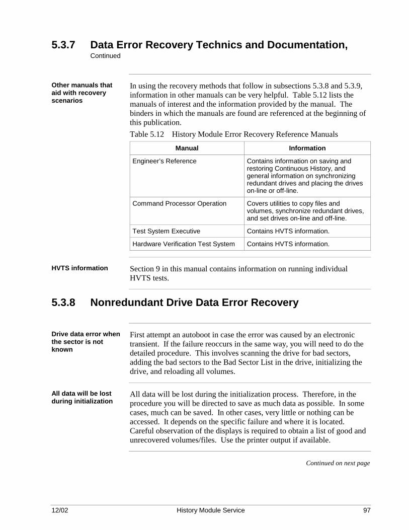
12/02 History Module Service 97
5.3.7 Data Error Recovery Technics and Documentation, Continued
Other manuals that aid with recovery scenarios
In using the recovery methods that follow in subsections 5.3.8 and 5.3.9, information in other manuals can be very helpful. Table 5.12 lists the manuals of interest and the information provided by the manual. The binders in which the manuals are found are referenced at the beginning of this publication. Table 5.12 History Module Error Recovery Reference Manuals
Manual Information
Engineer’s Reference Contains information on saving and restoring Continuous History, and general information on synchronizing redundant drives and placing the drives on-line or off-line.
Command Processor Operation Covers utilities to copy files and volumes, synchronize redundant drives, and set drives on-line and off-line.
Test System Executive Contains HVTS information.
Hardware Verification Test System Contains HVTS information.
HVTS information Section 9 in this manual contains information on running individual
HVTS tests.
5.3.8 Nonredundant Drive Data Error Recovery
Drive data error when the sector is not known
First attempt an autoboot in case the error was caused by an electronic transient. If the failure reoccurs in the same way, you will need to do the detailed procedure. This involves scanning the drive for bad sectors, adding the bad sectors to the Bad Sector List in the drive, initializing the drive, and reloading all volumes.
All data will be lost during initialization
All data will be lost during the initialization process. Therefore, in the procedure you will be directed to save as much data as possible. In some cases, much can be saved. In other cases, very little or nothing can be accessed. It depends on the specific failure and where it is located. Careful observation of the displays is required to obtain a list of good and unrecovered volumes/files. Use the printer output if available.
Continued on next page

12/02 History Module Service 98
5.3.8 Nonredundant Drive Data Error Recovery, Continued
Loading the personality software
Use the procedure in Table 5.13 to load the personality. If the HMI personality software is available on the History Module, you can do a personality change directly, by selecting the LOAD/DUMP target on the History Module Status display. If this is the case, skip Step 1 (it is not necessary to shut down the node to do a personality change). Table 5.13 History Module Personality Loading Procedure
Step Action
1 Perform a node shutdown of the History Module. See the text above.
2 Load the HMI personality into the History Module.
3 Attempt to save as much data as possible using the BACKUP function. Keep detailed records of which volumes/files were recovered and which must be reloaded from an alternate known good source.
4 Attempt to save Continuous History files. Keep detailed records of which volumes/files were recovered and which were lost.
5 Load HVTS and run the SCMD test using Subtest 19. This test can be configured to do a complete surface “Read Check” and automatically add any bad sectors it encounters to the existing defect list (Bad Sector List). A short period (approximately 10 minutes) of running Subtest 14 will certify the read/write capability of the drive. Additional tests should be run if there is any doubt concerning the drive’s functionality.
An alternate method of drive recovery would be to completely reformat the drive using Subtest 21 of the SCMD test under HVTS. This test must be configured to add bad sectors (HVTS refers to these as defective blocks) to the existing defect list (Bad Sector List). Never run this test configured to clear the Bad Sector List.
This HVTS testing could reveal that the drive is defective and must be replaced.
6 Load the HMI personality and perform a drive initialization.
7 Restore to the History Module, the data saved in Steps 3 and 4.
8 Load additional volumes/files from alternate sources noted in Step 3. History data that could not be saved as noted in Step 4 remains lost.
9 Load the HMO personality by performing a History Module autoboot.
10 Enable the saving of Continuous History data and any other normal functions required to restore complete system operation.
Continued on next page

12/02 History Module Service 99
5.3.8 Nonredundant Drive Data Error Recovery, Continued
ATTENTION ATTENTION—In some cases, it may be desirable to quickly replace the drive to save the time needed for the HVTS tests. HVTS testing will take approximately 1 hour if no additional problems are discovered. Replacement drives come preformatted and require only a History Module initialization and data restore operation. The removed drive can be tested/reclaimed using HVTS at a more convenient time, or on alternate equipment.
Drive data error when the sector is known
The circumstances will dictate the urgency in restoring the complete functionality of the History Module. The best maintenance strategy to use will depend on the nature of the failure and the criticality of the lost functionality. The alternatives that are available, listed in probable order of increasing time to perform, are as follows: 1. Continue running with reduced functionality and repair the drive when
more convenient. This may not be practical if the functionality that was lost due to the error is critical to the process.
2. Attempt a quick fix by using the SMCC Sector Initialization/Reassignment function. Refer to subsection 5.3.13. There are two variations that can occur.
The nature of the error is such that initialization and total reload of the drive is not required. After using the SMCC Sector Initialization/Reassignment function, reload the bad file from backup and resume operation.
The nature of the error is such that the drive must be initialized and reloaded. Save as much data as possible, use the SMCC Initialize/Reassign Sector function, initialize the drive, reload the entire drive, and resume operation.
3. Remove and replace the drive, initialize the new drive, and restore all data.
4. Use HVTS off-line and attempt to recover the drive. 5. If a quick fix procedure is to be used, you must determine whether or
not drive initialization and full reload will be required. The drive must be initialized and fully reloaded if one of the following situations is true.
The status of the affected volume is CORRUPTED on the Volume Status display. Refer to subsection 5.3.12.
The bad file is in one of the following volumes: Maintenance System software Journals Continuous History data (except CM files, assuming backup copy) Checkpoint files
Continued on next page
12/02 History Module Service 100
5.3.8 Nonredundant Drive Data Error Recovery, Continued
Two quick fix procedures
Two quick fix procedures are available. They are described below. If one of the above situations is true, you must use the procedure that incorporates initialization and reload of the disk. If the status of the affected volume is DEGRADED on the Volume Status display and the file is not in one of the volumes indicated above, you can use the procedure that does not incorporate initialization and reloading the drive.
Continued on next page

12/02 History Module Service 101
5.3.8 Nonredundant Drive Data Error Recovery, Continued
Quick fix procedure when drive initialization and reload are not required
When drive initialization and reloading are not required, use the procedure in Table 5.14. If the HMI personality software is available in the History Module, you can do a personality change directly using the LOAD/DUMP target on the History Module Status display. If this is the case, skip Step 1. It is not necessary to shut down the node to do a personality change. Table 5.14 Data Error Recovery Procedure – Init/Reload Not Required
Step Action
1 Perform a node shutdown of the History Module. See above text.
2 Load the History Module Initialization (HMI) personality software.
3 Initialize the bad sector using the SMCC function. This writes zeros into the bad sector.
4 Using utility commands, reload the known bad file from a known good source. This could be from a previously saved copy or some original source of the file. If the file in error was a checkpoint file, a complete set of files from a previous “good” checkpoint must be reloaded. Checkpoint files must be in synchronization with each other.
5 Using utility commands, verify that the file in question can be read successfully by copying it from the HM to some scratch media. If this is successful, the quick repair is complete. Continue with Step 9.
6 If steps 4-5 were not successful, a bad spot exists on the drive media. Use the SMCC feature to reassign the known bad sector to the Bad Sector List. Each drive has many spare sectors. Reassigning a bad sector to the Bad Sector List uses one of the available spare sectors. The sectors added to the Bad Sector List will be lost forever.
7 Using utility commands, reload the known bad file from a known good source again. This should repair the degraded file.
8 Using utility commands, verify that the file in question can now be read successfully.
9 Load the History Module Operating (HMO) personality software by performing a History Module autoboot.
10 Initiate the collection of history data, if needed.
11 Restart the function that was aborted when the History Module failure was detected.
ATTENTION ATTENTION—If you use the Sector Reassignment function, be aware that it does have one undesirable feature. Some of the sectors that contain the original file will be lost from the Sector Allocation tables. These lost sectors cannot be reclaimed until an initialization of the complete drive is accomplished. This will necessitate a complete save, initialization, and reload operation. Fortunately, it can be scheduled as a planned activity.

12/02 History Module Service 102
5.3.8 Nonredundant Drive Data Error Recovery, Continued
Quick fix procedure when drive initialization and reload are required
Use the procedure in Table 5.15 when drive initialization and reload are required. If the HMI personality software is available in the History Module, you can do a personality change directly using the LOAD/DUMP target on the History Module Status display. If this is the case, skip Step 1. It is not necessary to shut down the node to do a personality change. Table 5.15 Data Error Recovery Procedure – Init/Reload Required
Step Action
1 Perform a node shutdown of the History Module. See the above text.
2 Load the History Module Initialization (HMI) personality software.
3 Attempt to save as much History Module data as possible using the BACKUP function. Keep detailed records of which volumes/files were recovered and which must be reloaded from an alternate known good source.
4 Attempt to save Continuous History files. Keep detailed records of which volumes/files were recovered and which were lost.
5 Reassign the bad sector using the SMCC function.
Initialization of the sector can be attempted in place of reassignment of the sector. However, a marginal sector can initialize properly and then become as a problem later. The recovery process for active file problems requires too much time to implement at this point.
6 Initialize the drive.
7 Restore the data saved in Steps 3 and 4 to the History Module.
Procedures for restoring Continuous History data are provided in the Customer Release Guide.
8 Load additional volumes/files from alternate sources, noted in Step 3. History Module data that was not saved, noted in Step 4, remains lost.
9 Load the HMO personality by performing a History Module autoboot.
10 Enable the saving of Continuous History Data and any other normal functions required to restore complete system operation.
ATTENTION ATTENTION—If you use the Sector Reassignment function, be aware that it does have one undesirable feature. Some of the sectors that stored the original file will be lost from the Sector Allocation tables. These lost sectors cannot be reclaimed until an initialization of the complete drive is accomplished. This will necessitate a complete save, initialization, and reload operation. Fortunately, it can be scheduled as a planned activity.

12/02 History Module Service 103
5.3.9 Redundant Drive Data Error Recovery
Redundant drive data error recovery when the sector is not known
This failure could be a drive’s electronic failure or it could be a sector-related problem where the software is unable to identify the sector address. In either case, an exact diagnosis is not possible without shutting down the History Module and running the HVTS off-line tests. One attempt to “synch” the drive should be made in case the error was transient in nature. If this is successful, the problem is resolved. If not, HVTS is required or the drive must be replaced. The drive can be replaced while the History Module continues full operation using the redundant (backup) drive. Replacing the defective drive while its redundant partner is in full operation is accomplished using the procedure in Table 5.16. Use extreme care to prevent the accidental shutdown of the working drive(s). Table 5.16 Redundant Drive Data Error Recovery Procedure – Sector Not Known
Step Action
1 Use utility command OFF to set the suspected drive off-line.
2 If the History Module has redundant dual drives (4 drives), use the utility command OFF to set all volumes on both Disk drives in the same Winchester Drive Tray off-line.
3 Remove power from the tray that contains the defective drive.
4 Replace the defective drive using the procedures provided in this manual, Sections 4 and 5. Pay particular attention to the drive’s jumper block selections and whether termination modules should be installed (front drive only).
5 Reapply power to the tray containing the replaced drive.
6 Use the utility command SYNCH to data synchronize the drive(s) that is presently in the off-line state. One SYNCH command will data synchronize both redundant drives, if present.
Continued on next page

12/02 History Module Service 104
5.3.9 Redundant Drive Data Error Recovery, Continued
Reclaiming a defective redundant drive with off-line HVTS
It is possible that a defective redundant drive containing a media defect can be reclaimed by running the off-line HVTS using Subtest 19 in the SCMD test. This test can be configured to do a complete surface “READ CHECK” and automatically add any bad sectors (called “defective blocks” by HVTS) that the test encounters to the existing Bad Sector List (called “Defect Data List” by HVTS). A short period of running Subtest 14 will certify the read/write capability of the drive. A “sync” operation is required to place the drive on-line once the node autoboots with the History Module Operating (HMO) personality software. The History Module must be taken off-line to run the HVTS procedure. This can be done at a convenient time, or the drive can be removed and placed in a less critical History Module to perform the HVTS recovery attempt.
Alternate method of drive recovery An alternate method of drive recovery would be to completely reformat the drive using Subtest 21 of the SCMD test under HVTS. This test must be configured to add bad sectors to the existing Bad Sector List. drive data error recovery when the sector is known
During the following procedure, the History Module remains fully operational, running with the redundant (backup) drive. Data errors are most frequently caused by a defective spot on the drive media. However, an electrical transient can give the very same symptom. This procedure recommends first attempting an initialization of the suspect sector (writing zeros) and reloading the affected data through a “SYNCH” operation. If this does not correct the problem, perform the Sector Reassignment function using the procedure in Table 5.17.
Table 5.17 Redundant Drive Data Error Recovery Procedure – Sector Known
Step Action
1 Initialize the bad sector (write zeros) using the SMCC Sector Initialization/Reassignment function covered in subsection 5.3.13. If an error occurs, use the Sector Reassignment option of the SMCC Sector Initialization/Reassignment function.
2 Use the utility command SYNCH to synchronize the data on the problem drive with the working redundant partner.
Continued on next page

12/02 History Module Service 105
5.3.9 Redundant Drive Data Error Recovery, Continued
Synchronization operation
A “SYNCH” operation copies the data resident on the working (primary) drive to the drive that is being synchronized. Only the necessary volumes and files are copied. The final result provides a functional on-line redundant drive with identical data as the primary drive. System demands on the History Module will affect the total time for synchronization. The “SYNCH” operation can take up to 45 minutes. Any system activity which alters the contents of the working drive during the “SYNCH” operation will also be passed on to the drive being synchronized. The successful conclusion of the synchronization operation places the synchronized drive on-line with its working redundant partner.
If the sector problem returns
If the problem with the sector in question returns, it must be assumed that there is a bad spot on the disk surface which must be avoided. Repeat the procedure described, but instead of initializing the sector in Step 1, reassign the sector to the Bad Sector List using the SMCC Sector Initialization/Reassignment function. With the Type II drives the sectors are re-assigned automatically.

12/02 History Module Service 106
5.3.10 Control Track Error Recovery for Sectors 1-31
Overview The following procedures address Control Track recovery for sectors
1 through 31 on the History Module. Both redundant and nonredundant drives are covered in the procedures.
Redundant drive 5 or 3 has a Control Track error
Use the recovery procedure in Table 5.18 for an error condition in sectors 1 through 31 of the Control Track on drive 5 or 3.
Table 5.18 Drive 5 or 3 Control Track Error Recovery Procedure – Redundant Drives
Step Action
1 For a Control Track error on drive 5 or 3, place its redundant partner, drive 4 or 2, respectively, OFFLINE by using the appropriate Universal Station display.
2 Initialize or reassign the sector containing the error.
3 If sectors 1 through 7 on the drive have been initialized or reassigned, rewrite the Boot record on the drive.
4 Autoboot the History Module twice by cycling power to the History Module. Wait for an OK status between the first and second autoboot.
5 Synchronize drive 4 or 2 with drive 5 or 3, respectively.
Redundant drive 4 or 2 has a Control Track error
Use the recovery procedure in Table 5.19 for an error condition in sectors 1 through 31 of the Control Track on drive 4 or 2.
Table 5.19 Drive 4 or 2 Control Track Error Recovery Procedure – Redundant Drives
Step Action
1 For a Control Track error on drive 4 or 2, place the drive OFFLINE by using the appropriate Universal Station display.
2 Initialize or reassign the sector containing the error.
3 Synchronize drive 4 or 2 with drive 5 or 3, respectively.
Continued on next page

12/02 History Module Service 107
5.3.10 Control Track Error Recovery for Sectors 1-31, Continued
Nonredundant drive 5 or 3 has a Control Track error
Use the recovery procedure in Table 5.20 for an error condition in sectors 1 through 31 of the Control Track on drive 5 or 3.
Table 5.20 Drive 5 or 3 Control Track Error Recovery Procedure – Nonredundant Drives
Step Action
1 Load the HMI personality into the History Module.
2 Initialize or reassign the sector containing the error.
3 If sectors 1 through 7 of drive 5 have been initialized or reassigned, rewrite the Boot record on the drive.
4 Autoboot the History Module twice by cycling power to the History Module. Wait for an OK status between the first and second autoboot.

12/02 History Module Service 108
5.3.11 Status Detail Display
Accessing the Status Detail display
The Status Detail display for a History Module shows the status for each drive and each function, such as Continuous History, History Journals, and other displays. It also contains a target that provides access to the drive’s Volume Status display (Object Detail display). See Figure 5.3. Figure 5.3 Status Detail Display
7877
Status Detail display access procedure
Use the procedure in Table 5.21 to access the Status Detail Display.
Table 5.21 Accessing the Status Detail Display Procedure
Step Action
1 Choose the System Status display on the console with the SYSTEM STATUS key.
2 Select the HISTORY MODULES target on the System Status display. This produces the History Modules display.
3 Select the desired History Module on the History Modules display.
4 Select the STATUS DETAIL target. This provides the Status Detail display for the selected History Module as shown in Figure 5.3.
Continued on next page

12/02 History Module Service 109
5.3.11 Status Detail Display, Continued
Status Detail display status
For any status indication other than “OK,” one of the following error messages will be displayed.
SYNCHRONIZE SOURCE ERROR - SECTOR xxxxxxx SYNCHRONIZE DESTIN ERR. - SECTOR xxxxxxx NON RECOV ERR, 1 CTL TRK - SECTOR xxxxxxx NON RECOV VVID ERROR - SECTOR xxxxxxx - volm>filename.ex NON RECOV VVAT ERROR - SECTOR xxxxxxx - volm>filename.ex NON RECOV FAB ERROR - SECTOR xxxxxxx - volm>filename.ex NON RECOV SAT ERROR - SECTOR xxxxxxx - volm>filename.ex NON RECOV PDB ERROR - SECTOR xxxxxxx - volm>filename.ex RECOV DISK DATA ERROR - SECTOR xxxxxxx - volm>filename.ex NON RECOV DATA ERROR - SECTOR xxxxxxx - volm>filename.ex ERROR WITH BOTH CTL TRKS - SECTOR xxxxxxx NON RECOV DEVICE ERROR - SECTOR xxxxxxx - volm>filename.ex DISK CONTROLLER ERROR
Refer to the Messages Directory manual for assistance in interpreting the message.
Continued on next page

12/02 History Module Service 110
5.3.12 Volume Status Display
Volume Status display The Volume Status display is a two-page Object Detail display that shows
the status of all the volumes of each drive in the History Module. This information is important when troubleshooting and repairing drive problems.
Volume Status display access procedure
Use the procedure in Table 5.22 to access the Volume Status displays.
Table 5.22 Volume Status Display Access Procedure
Step Action
1 Choose any NOTIFICATION line on the Status Detail display, as illustrated in Figure 5.4, and the VIEW OBJECT DETAIL target will appear at the bottom of the screen.
2 Select the VIEW OBJECT DETAIL target. The Volume Status display will appear as shown in Figures 5.5 and 5.6. This is a two-page display that presents the status of each of the four possible drives and the status of the volumes stored on each drive.
Figure 5.4 Status Detail Display (Drive Selected)
7878
Continued on next page

12/02 History Module Service 111
5.3.12 Volume Status Display, Continued
Volume Status display illustrations
The Volume Status displays are illustrated in Figures 5.5 and 5.6.
Figure 5.5 Volume Status Display (Page 1)
7879
Figure 5.6 Volume Status Display (Page 2)
7880
Continued on next page

12/02 History Module Service 112
5.3.12 Volume Status Display, Continued
Volume Status display status
The status on the Volume Status display that is of interest to the troubleshooting process are listed in Table 5.23. Table 5.23 Volume Status Display Status
Status Explanation
OK The normal error free status.
DEGRADED An error in a file, but other files in the volume are accessible.
CORRUPTED The entire volume is inaccessible. Possibly an error in the directory.
SYN_IP Synchronization is in process, synchronizing a drive with its redundant partner so that both have identical data.
NOT INITIALIZED The volume has been created but has not been synchronized. It has been placed off-line. Performing a synchronization will place the volume on-line. This state will be seen on drives 04 and 03 after the HMI personality has been run.
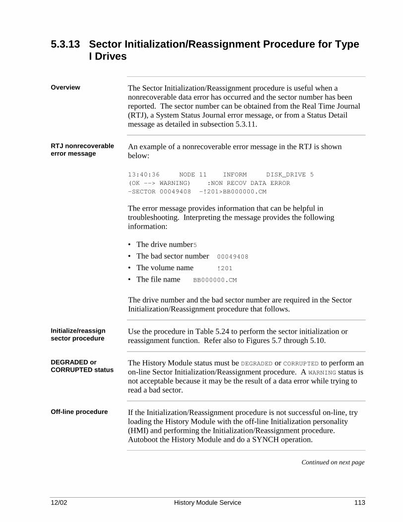
12/02 History Module Service 113
5.3.13 Sector Initialization/Reassignment Procedure for Type I Drives
Overview The Sector Initialization/Reassignment procedure is useful when a
nonrecoverable data error has occurred and the sector number has been reported. The sector number can be obtained from the Real Time Journal (RTJ), a System Status Journal error message, or from a Status Detail message as detailed in subsection 5.3.11.
RTJ nonrecoverable error message
An example of a nonrecoverable error message in the RTJ is shown below: 13:40:36 NODE 11 INFORM DISK_DRIVE 5 (OK --> WARNING) :NON RECOV DATA ERROR -SECTOR 00049408 -!201>BB000000.CM The error message provides information that can be helpful in troubleshooting. Interpreting the message provides the following information: • The drive number 5 • The bad sector number 00049408 • The volume name !201 • The file name BB000000.CM The drive number and the bad sector number are required in the Sector Initialization/Reassignment procedure that follows.
Initialize/reassign sector procedure
Use the procedure in Table 5.24 to perform the sector initialization or reassignment function. Refer also to Figures 5.7 through 5.10.
DEGRADED or CORRUPTED status
The History Module status must be DEGRADED or CORRUPTED to perform an on-line Sector Initialization/Reassignment procedure. A WARNING status is not acceptable because it may be the result of a data error while trying to read a bad sector.
Off-line procedure If the Initialization/Reassignment procedure is not successful on-line, try
loading the History Module with the off-line Initialization personality (HMI) and performing the Initialization/Reassignment procedure. Autoboot the History Module and do a SYNCH operation.
Continued on next page
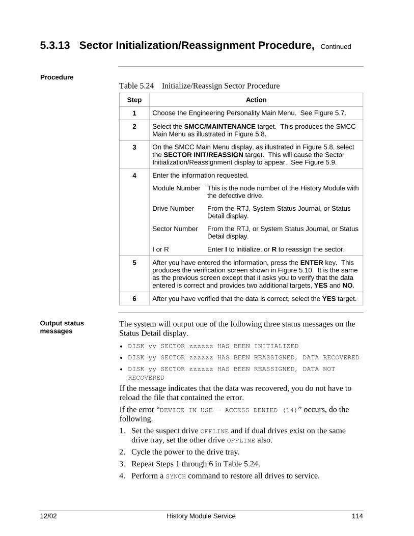
12/02 History Module Service 114
5.3.13 Sector Initialization/Reassignment Procedure, Continued
Procedure
Table 5.24 Initialize/Reassign Sector Procedure
Step Action
1 Choose the Engineering Personality Main Menu. See Figure 5.7.
2 Select the SMCC/MAINTENANCE target. This produces the SMCC Main Menu as illustrated in Figure 5.8.
3 On the SMCC Main Menu display, as illustrated in Figure 5.8, select the SECTOR INIT/REASSIGN target. This will cause the Sector Initialization/Reassignment display to appear. See Figure 5.9.
4 Enter the information requested.
Module Number This is the node number of the History Module with the defective drive.
Drive Number From the RTJ, System Status Journal, or Status Detail display.
Sector Number From the RTJ, or System Status Journal, or Status Detail display.
I or R Enter I to initialize, or R to reassign the sector.
5 After you have entered the information, press the ENTER key. This produces the verification screen shown in Figure 5.10. It is the same as the previous screen except that it asks you to verify that the data entered is correct and provides two additional targets, YES and NO.
6 After you have verified that the data is correct, select the YES target.
Output status messages
The system will output one of the following three status messages on the Status Detail display. • DISK yy SECTOR zzzzzz HAS BEEN INITIALIZED
• DISK yy SECTOR zzzzzz HAS BEEN REASSIGNED, DATA RECOVERED
• DISK yy SECTOR zzzzzz HAS BEEN REASSIGNED, DATA NOT RECOVERED
If the message indicates that the data was recovered, you do not have to reload the file that contained the error. If the error “DEVICE IN USE – ACCESS DENIED (14)” occurs, do the following. 1. Set the suspect drive OFFLINE and if dual drives exist on the same
drive tray, set the other drive OFFLINE also. 2. Cycle the power to the drive tray. 3. Repeat Steps 1 through 6 in Table 5.24. 4. Perform a SYNCH command to restore all drives to service.

12/02 History Module Service 115
5.3.13 Sector Initialization/Reassignment Procedure, Continued
Engineering Personality Main Menu display
The Engineering Personality Main Menu display is illustrated in Figure 5.7.
Figure 5.7 Engineering Personality Main Menu Display
ENGINEERING PERSONALITY MAIN MENU
27 Jul 91 06:28:06 2
COMMAND PROCESSOR
SUPPORT UTILITIES
SYSTEM MENU SYSTEM STATUS CONSOLE STATUS
SMCC/ MAINTENANCE R400 (C) Honeywell Inc., 1984
Support Functions and Utility Functions
UNIT NAMES
AREA NAMES
CONSOLE NAMES
LCN NODES
SYSTEM WIDE VALUES
VOLUME CONFIGURATION
HIWAY GATEWAY
LOGIC BLOCKS
APPLICATION MODULE
COMPUTING MODULENETWORK INTERFACE
BUILDER COMMANDS
PICTURE EDITOR
FREE FORMAT LOGS
BUTTON CONFIGURATION
HM HISTORY GROUPS
DOCUMENTATION TOOL
AREA DATA BASE
MODULE
6134
SMCC Main Menu display
The SMCC Main Menu display is illustrated in Figure 5.8.
Figure 5.8 SMCC Main Menu Display
For Information On Funtions And Options Displayed On this Menu, Position The Cursor On the Desired Target And Press HELP.
SMCC MAIN MENU
14 Jul 91 12:55:29
MODULE MEMORY
SYSTEM MAINT JOURNAL
REV/CONFIG STATUS
HIWAY BOX MEMORY
ACTIVE MAINT JOURNAL
PROBE FAILED MODULE
MODULE ERROR
MAIN MENUSECTOR INIT./REASSIGN
6135
Continued on next page

12/02 History Module Service 116
5.3.13 Sector Initialization/Reassignment Procedure, Continued
Sector Initialization/ Reassignment Menu display
The Sector Initialization/Reassignment Menu display is illustrated in Figure 5.9.
Figure 5.9 Sector Initialization/Reassignment Menu Display
For Information On Functions And Options Displayed On This Menu, Position The Cursor On The Desired Target And Press HELP.
Enter PARAMETERS - ENTER Module Number : ENTER Drive Number : ENTER Sector Number : ENTER Sector Initialize/Sector Reassign : (I or R)
23 Jul 91 21:15:47 1
SECTOR INITIALIZATION/REASSIGNMENT
WARNING - Use of Function Will Permanently Reassign Sector on the Requested HM. This Should Only Be Used After receipt of a System Message Requesting Action Be Taken Against a Specific HM Drive.
(1 To 96) (0 To 7) (1 To 99999999)
6138
Sector Initialization/ Reassignment Menu (Verification)
The Sector Initialization/Reassignment Menu (Verification) display is illustrated in Figure 5.10.
Figure 5.10 Sector Initialization/Reassignment Menu (Verification) Display
For Information On Functions And Options Displayed On This Menu, Position The Cursor On The Desired Target And Press HELP.
Enter PARAMETERS - ENTER Module Number : ENTER Drive Number : ENTER Sector Number : ENTER Sector Initialize/Sector Reassign : (I or R)
23 Jul 91 21:15:47 1
SECTOR INITIALIZATION/REASSIGNMENT
WARNING - Use of Function Will Permanently Reassign Sector on the Requested HM. This Should Only Be Used After receipt of a System Message Requesting Action Be Taken Against a Specific HM Drive.
(1 To 96) (0 To 7) (1 To 99999999)
43 5 99999999
I
YES NOVERIFY THAT THE DATA ENTERED IS CORRECT?
6139

12/02 History Module Service 117
Section 6 – WREN Type History Module Disassembly
6.1 Overview
Section contents The topics covered in this section are:
Topic See Page 6.1 Overview 119 6.2 Electronics Module Disassembly 120 6.3 Nonredundant Winchester Drive Module Disassembly 121 6.3.1 Fan Assembly Removal 122 6.3.2 Slide Tray Assembly Removal 122 6.3.3 Power Supply/Disk Drive Removal 123 6.4 Redundant Winchester Drive Module Disassembly 124 6.4.1 Fan Assembly Removal 125 6.4.2 Slide Tray Assembly Removal 125 6.4.3 Power Supply/Disk Drive Removal 126
CAUTION CAUTION—Risk of electric shock
Purpose This section describes disassembly of the major components of the History Module, including removal of the electronics boards, Winchester disk drive(s), power supply, fan assembly, and disconnection of the module cabling.
WARNING WARNING—Do not attempt any disassembly or repair the History Module without first conducting orderly testing and troubleshooting procedures. Return to Section 4 if you do not have a clear understanding of which part in the History Module has failed. YOU MUST OBTAIN OPERATOR PERMISSION BEFORE PLACING THE HISTORY MODULE OFF-LINE FOR TESTING.
Before disassembly Disassemble the major components of the History Module only to the extent necessary to repair or replace a defective part. For a nonredundant drive system, always use the Universal Station to select the failed node from the History Module Status display and perform a SHUTDOWN command. For a redundant drive system, place the drive(s) off-line in the Winchester Drive Module to be repaired. Allow at least a 30-second drive spin-down time before attempting to remove a Winchester Drive tray. If a drive is jarred while its disks are spinning, there is “head crash” potential.
Continued on next page

12/02 History Module Service 118
6.1 Overview, Continued
Before proceeding Before proceeding:
IF the failure is in… SHUT DOWN, then go to …
The electronics module with a failure of the fan assembly, the power supply, or on a circuit board.
Subsection 6.2
A Winchester Drive Module with a failure of the fan assembly, the power supply, or in one of the drives (WREN III, 210 MB, 445 MB, 875 MB, or 1.8 GB). The drive is not configured as a redundant disk drive.
Subsection 6.3
IF the failure is in… DO NOT SHUT DOWN,
but go to …
A Winchester Drive Module that is part of a redundant drive History Module. The failure is in the fan assembly, the power supply, or a disk drive in one of the modules.
Subsection 6.4
Now go to the appropriate subsection for disassembly instructions.
6.2 Electronics Module Disassembly
Overview Refer to the Five/Ten-Slot Module Service or Dual Node Service manual
for the applicable disassembly procedure. To protect equipment from voltage transients and ensure reliable operation, always remove power from the History Module before removing or replacing circuit boards, or any other component in the electronics module.
CAUTION CAUTION—Many of the assemblies used in this module are likely to contain electrostatically sensitive devices. Use a personnel grounding strap and grounded work surfaces/equipment. Store and transport parts only on electrostatically safe containers.

12/02 History Module Service 119
6.3 Nonredundant Winchester Drive Module Disassembly
Overview Use these instructions in this subsection to remove the fan assembly and
the slide tray assembly in the Winchester Drive Module(s) that is a component of a nonredundant drive History Module. The slide tray assembly contains a drive power supply assembly and disk drive(s), and can be disassembled. Go to the specific instructions in subsection 6.4 if you are disassembling a Winchester Drive Module for a redundant drive History Module.
Component references
Disassemble the module only to the extent necessary to repair or replace a defective part. The item numbers referenced in this section are keyed to ballooned numbers in Figure 6-1. The item numbers are also referenced in Section 7, WREN Type History Module Assembly, and Section 10, Spare Parts. Figure 6-1 Winchester Drive Module Exploded View
51
6
4
3
2
8
7
6347
Preliminary disassembly
Remove the front cover by turning the two quarter-turn fasteners and freeing the cover tabs from the chassis slots. Place the power switch on the power supply (4) in the OFF position and note that the indicator on the power supply extinguishes.

12/02 History Module Service 120
6.3.1 Fan Assembly Removal
Procedure Remove the fan assembly (3) by turning the two fasteners and sliding the
assembly out of the chassis. The individual fans are not a replaceable item, so the complete assembly must be replaced at the Optimum Replaceable Unit (ORU) level.
6.3.2 Slide Tray Assembly Removal
No shipping locks The WREN III, 210 MB, 445 MB, 875 MB, and 1.8 GB drives have no
shipping locks. They automatically lock when power is removed and unlock when power is applied to the drive.
Disassembly procedure
Referencing Figure 6-1, use the following procedure to disassemble the slide tray assembly. 1. Release the cable clamp(s) that holds the SCSI bus ribbon cable to the
inside surface of the module chassis or the tray assembly. 2. Disconnect the AC power cord (2) from the power supply and the fan
assembly cable (3) from its mating connector in front of the power supply on the slide tray assembly. Loosen the bale-headed fasteners on the tray assembly and pull the tray assembly out of the module chassis about 7.5 centimeters (3 inches). Use extreme care not to damage ribbon cables on a sharp edge of the tray assembly or the module chassis.
Remove the connectors from the disk drive (5) on the tray assembly. Note the dress of the ribbon cable(s) and the position of the ribbon cable connectors where they enter the drive. In particular, note the orientation of the stripe on the ribbon cable(s).
The single SCSI bus ribbon cable for the WREN III, 210 MB, 445 MB, 875 MB, or 1.8 GB drive routes over the tray assembly between the drive and the fan assembly. The cable for WREN III drives is slipped under the edge of the drive(s), or clamped to the tray assembly for 210 MB, 445 MB, 875 MB, or 1.8 GB drive to prevent it from interfering with the rotating fan blades.
3. Once all the ribbon cables have been disconnected, you can fully remove the tray assembly from the module chassis and place it on a work surface for further disassembly.

12/02 History Module Service 121
6.3.3 Power Supply/Disk Drive Removal
Disassembly procedure
Referencing Figure 6-1, use the following procedures to disassemble the power supply and/or disk drives. 1. If replacing the power supply assembly (4), tag and remove the wires
connected to the power supply’s terminal board (6). Detach the power supply from the tray assembly by removing four screws, lock washers, and flat washers from beneath the tray assembly.
2. If replacing a disk drive (5), pay particular attention to the position of the jumpers and the presence or absence of a bus terminator module (WREN III) or bus termination resistor modules (210 MB or 445 MB) on the drive. These subjects are covered in detail in Section 7.
3. Disconnect the drive’s power cable. Detach the drive by removing four screws, lock washers, and flat washers from beneath the tray assembly.

12/02 History Module Service 122
6.4 Redundant Winchester Drive Module Disassembly
Overview If you are considering disassembling a Winchester Drive Module
containing redundant drives, you probably were informed by a History Module Status display that a DISKPROB exists because of either a power supply failure or a disk drive failure.
Fan failure If the fan assembly has failed, the red Fan Alarm LED is illuminated.
Check drive status Be sure you request status through the Command Processor to verify the
address of the disk that is OFFLINE, and that its redundant partner is still OK.
General Refer to Figure 6-2 to find the physical location of the OFFLINE drive, then
disassemble that Winchester Drive Module and remove its slide tray assembly using the procedures that follow. The item numbers referred to in this section are keyed to ballooned numbers in Figure 6-1. The item numbers are also used in Section 9, WREN Type History Module Assembly, and Section 12, Spare Parts. Figure 6-2 Redundant Drive Positioning and Address Assignments
16776Redundant Single Drives Redundant Dual Drives
Drive 5 Address = 5
Drive 4 Address = 4
Drive 3 Address = 3
Drive 4 Address = 4
Drive 2 Address = 2
Drive 2 Address = 5
Preliminary disassembly
Remove the front cover by turning the two quarter-turn fasteners and freeing the cover tabs from the chassis slots.
CAUTION CAUTION—DO NOT REMOVE POWER UNTIL INSTRUCTED IN THE STEPS THAT FOLLOW.
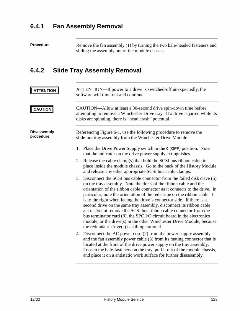
12/02 History Module Service 123
6.4.1 Fan Assembly Removal
Procedure Remove the fan assembly (1) by turning the two bale-headed fasteners and
sliding the assembly out of the module chassis.
6.4.2 Slide Tray Assembly Removal
ATTENTION ATTENTION—If power to a drive is switched-off unexpectedly, the software will time-out and continue.
CAUTION CAUTION—Allow at least a 30-second drive spin-down time before attempting to remove a Winchester Drive tray. If a drive is jarred while its disks are spinning, there is “head crash” potential.
Disassembly procedure
Referencing Figure 6-1, use the following procedure to remove the slide-out tray assembly from the Winchester Drive Module. 1. Place the Drive Power Supply switch in the 0 (OFF) position. Note
that the indicator on the drive power supply extinguishes. 2. Release the cable clamp(s) that hold the SCSI bus ribbon cable in
place inside the module chassis. Go to the back of the History Module and release any other appropriate SCSI bus cable clamps.
3. Disconnect the SCSI bus cable connector from the failed disk drive (5) on the tray assembly. Note the dress of the ribbon cable and the orientation of the ribbon cable connector as it connects to the drive. In particular, note the orientation of the red stripe on the ribbon cable. It is to the right when facing the drive’s connector side. If there is a second drive on the same tray assembly, disconnect its ribbon cable also. Do not remove the SCSI bus ribbon cable connector from the bus terminator card (8), the SPC I/O circuit board in the electronics module, or the drive(s) in the other Winchester Drive Module, because the redundant drive(s) is still operational.
4. Disconnect the AC power cord (2) from the power supply assembly and the fan assembly power cable (3) from its mating connector that is located at the front of the drive power supply on the tray assembly. Loosen the bale-fasteners on the tray, pull it out of the module chassis, and place it on a antistatic work surface for further disassembly.
12/02 History Module Service 124
6.4.3 Power Supply/Disk Drive Removal
Removal procedure Referencing Figure 6-1, use the following procedure to disassemble the
power supply and/or disk drive(s). 1. If replacing the power supply assembly (4), tag and remove the wires
connected to the power supply’s terminal board (6). Detach the power supply from the tray assembly by removing four screws, lock washers, and flat washers from beneath the tray assembly.
2. If replacing a disk drive (5), pay particular attention to the position of the jumpers and the presence or absence of a bus terminator module (WREN III) or termination resistor modules (210 MB or 455 MB) on the drive. These subjects are fully covered in Section 7.
3. Disconnect the drive’s power cable. Detach the drive by removing four screws, lock washers, and flat washers from beneath the tray assembly.

12/02 History Module Service 125
Section 7 – WDA Type I History Module Disassembly
7.1 Overview
Section contents The topics covered in this section are:
Topic See Page 7.1 Overview 127 7.2 History Module Disassembly 128 7.2.1 General Disassembly 129 7.2.2 Fan Assembly Removal 130 7.2.3 Power Supply Removal 130 7.2.4 Circuit Board Removal 131 7.2.5 Winchester Disk Assembly Removal 132 7.3 Winchester Drive Tray Disassembly 133 7.3.1 Winchester Disk Drive Removal 136
CAUTION CAUTION—Risk of electric shock
Purpose This section describes disassembly of the major components of the History
Module, including removal of the electronics boards, Winchester Disk Assembly, Winchester disk drive(s), power supply, fan assembly, and disconnection of the module cabling.
CAUTION CAUTION—Do not attempt any disassembly or repair the History Module without first conducting orderly testing and troubleshooting procedures. Return to Section 4 if you do not have a clear understanding of which part in the History Module has failed. YOU MUST OBTAIN OPERATOR PERMISSION BEFORE PLACING THE HISTORY MODULE OFF-LINE FOR TESTING.
Before disassembly Disassemble the major components of the History Module only to the
extent necessary to repair or replace a defective part. For a nonredundant drive system, always use the Universal Station to select the failed node from the History Module Status display and perform a SHUTDOWN command. For a redundant drive system, place the drive(s) off-line on the Winchester Drive Tray to be removed.
Continued on next page

12/02 History Module Service 126
7.1 Overview, Continued
Before proceeding Before proceeding:
IF the failure is in… SHUT DOWN, then go to …
The electronics and auxiliary components with a failure in the fan assembly, the power supply, or in a circuit board.
Subsection 7.2
The Winchester Disk Assembly with a failure of a drive, and the History Module is not configured for redundancy because only the right-hand Winchester Drive Tray exists.
Subsection 7.3
IF the failure is in… DO NOT SHUT DOWN,
but go to …
The Winchester Disk Assembly with a failure of a drive, and the History Module is configured for redundancy because both Winchester Drive Trays have one or two drives.
Subsection 7.3
Now go to the appropriate subsection for disassembly instructions.
7.2 History Module Disassembly
Overview Refer to the Five/Ten-Slot Module Service manual for any additional
disassembly procedure assistance. To protect the equipment from voltage transients and ensure reliable operation, always place the power supply ON/OFF switch in the OFF position before removing or replacing the circuit boards, power supply, fan assembly, cables, or the Winchester Disk Assembly. One or both Winchester Drive Trays can be removed while power is applied to the History Module because each has a power ON/OFF switch. Always follow proper ESD (Electrostatic Discharge) procedures when handling circuit boards or other electronic components.

12/02 History Module Service 127
7.2.1 General Disassembly
CAUTION CAUTION—Allow at least a 30-second drive spin-down time before attempting to remove a Winchester Drive tray. If a drive is jarred while its disks are spinning, there is “head crash” potential.
Preliminary Disassemble the module only to the extent necessary to repair or replace a
defective assembly or part. The item numbers referenced in this section are keyed to ballooned numbers in Figure 7-1. These item numbers are also used in Section 8, WDA Type History Module Assembly and Section 10, Spare Parts. Figure 3-1 is another view of the History Module assembly. Remove the front panel (1) by turning the two quarter-turn fasteners at the right side of the panel and swinging the panel outward until free from the chassis slots. Place the power switch on the power supply (2) in the OFF position and verify that all indicators on the power supply are extinguished.
Figure 7-1 WDA History Module Exploded View
6761
1
23
10
7
5
6
49
8
12
11
CAUTION CAUTION—Many of the assemblies used in this module are likely to contain electrostatically sensitive devices. Use a personnel grounding strap and grounded work surfaces/equipment. Store and transport parts only on electrostatically safe containers.

12/02 History Module Service 128
7.2.2 Fan Assembly Removal
Removal procedure Remove the fan assembly (3) by turning the two fasteners and sliding the
assembly out of the chassis. The individual fans are not a replaceable item, so the complete assembly must be replaced at the Optimum Replaceable Unit (ORU) level.
7.2.3 Power Supply Removal
Removal procedure Release the power supply (2) by simultaneously pulling outward on the
extractor levers located on each side of the assembly. Slide the power supply out of the History Module chassis after it has been released from its backpanel connectors. The circuit board in the power supply is not a replaceable item, so the complete assembly must be replaced if the board has failed.

12/02 History Module Service 129
7.2.4 Circuit Board Removal
Cable removal Disconnect those cables necessary for the removal of the associated circuit
board assembly. Three I/O circuit board assemblies have cables connected to them, the SPCII I/O (SPC2), WDI I/O (WDI), and LCN I/O (CLCN A/B).
SCSI bus ribbon cables
The SPCII I/O (SPC2) circuit board (8) and the WDI I/O (WDI) circuit board (9), located in slots 2 and 5, respectively, at the rear of the History Module chassis, are interconnected by two SCSI bus ribbon cables (10). The friction-fit connections are released by pulling outward on the individual connectors. Do not pull on the ribbon cable itself.
LCN coax cables The Local Control Network (LCN) trunk cables, A and B, connect to the
LCN I/O (CLCN A/B) circuit board (7) in slot 1 at the rear of the History Module chassis by coaxial T-connectors. Do not disconnect the cables from the T-connectors. Disconnect only the T-connectors from the board connectors. Removal of an LCN trunk cable connector from its T-connector interrupts the continuity of the network. Note where cables A and B connect. They are color-coded yellow (A) and green (B). Do not cross the cable connections.
K2LCN or K4LCN and SPC circuit boards
The K2LCN (11) or K4LCN (11) and SPC (12) circuit boards are removed by simultaneously pulling outward on the board extractors located on each side of the board and sliding the board out of the History Module chassis.
I/O circuit boards The I/O circuit boards, LCN I/O [CLCN A/B] (7) and SPCII I/O [SPC2]
(8), and the WDI I/O [WDI] (9), are located at the rear of the History Module chassis in the module’s I/O card cage. They are assigned to slots 1, 2, and 5, respectively. The circuit boards are removed by simultaneously pulling outward on the board extractors located on each side of the board and sliding the board out of the I/O card cage.

12/02 History Module Service 130
7.2.5 Winchester Disk Assembly Removal
Description The Winchester Disk Assembly (4) is composed of a chassis and two
Winchester Drive Trays, right-hand and optional left-hand, that reside in the chassis. The trays are interchangeable assemblies, but must be properly configured for their application in the History Module. Each tray is held in place by an extractor lever and by the friction of the tray’s mating connectors. The trays are removed from the assembly by pulling outward on their extractor lever and sliding the tray out of the chassis.
WDA removal The Winchester Disk Assembly is removed from the History Module
chassis by first removing two fasteners that are located towards the front of each side of the chassis. The Winchester Disk Assembly connectors mate with backpanel connectors in the slot 5 position, but are guided into position by the guide rails normally used for a circuit board in the slot 4 position. The friction of the backpanel connectors tends to hold the assembly in place. Assembly removal is initiated by first removing the fan assembly to gain access to the right side fastener. Both assembly fasteners are then removed, and the assembly is then pulled forward by grasping the metal partition dividing the tray compartments and sliding the assembly out of the History Module chassis along slot 4’s guide rails.
WDI circuit board replacement
Besides the Winchester Drive Trays, the Winchester Disk Assembly also contains the Winchester Drive Interface (WDI ) circuit board which is held in place by five Phillips-head screws, located at the corners and the forward center of the board, and available through access holes at the top of the assembly chassis. There is a spacer used with each fastener. The spacers are very important when mounting the circuit board, because without the spacers the circuit board will not mate properly with its backpanel connectors. Since it is very difficult to install the WDI circuit board using spacers, it is recommended that the circuit board not be replaced in the field. Instead, the Winchester Disk Assembly should be replaced if it is suspected that the circuit board has failed. The WDI circuit board cannot be ordered as a spare part.

12/02 History Module Service 131
7.3 Winchester Drive Tray Disassembly
Overview These instructions cover the disassembly of the right-hand or left-hand
Winchester Drive Tray and the removal of the Winchester disk drive(s) mounted on the tray. In a nonredundant History Module configuration, the left-hand Winchester Drive Tray will not be present. A Winchester Drive Tray can contain one (single drive) or two (dual) drives.
General You are probably removing a Winchester Drive Tray and replacing a drive
because you were informed by the History Module Status display that a DISKPROB exists. If you have redundant drives, be sure you request status from the Command Processor to verify the address of the failed drive, which is OFFLINE, and that its redundant partner is operational. Be sure both drives of a dual redundant configuration are OFFLINE.
Continued on next page

12/02 History Module Service 132
7.3 Winchester Drive Tray Disassembly, Continued
Before beginning disassembly
Before beginning disassembly, consider whether or not the History Module has redundant drives. If the module does not contain redundant drives, power can be removed from the drive(s) mounted on the right-hand Winchester Drive Tray, at the power supply or the tray by placing their respective power ON/OFF switch in the OFF position. Should the History Module contain redundant drives, then remove power only at the Winchester Drive Tray that contains the defective drive. Disassemble the Winchester Drive Tray only to the extent necessary to replace a defective part. The item numbers used in this subsection are keyed to ballooned numbers in Figures 7-2 and 7-3. Figure 7-2 Single-Drive Winchester Drive Tray Exploded View
6769
1
5
47
8 6
3
Figure 7-3 Dual-Drive Winchester Drive Tray Exploded View
6768
1
2
3
47
8 6
Continued on next page

12/02 History Module Service 133
7.3 Winchester Drive Tray Disassembly, Continued
CAUTION CAUTION—The drive(s) mounted on the tray is an electrostatically sensitive device. Use a grounding strap and grounded work surfaces/equipment. Store and transport parts only in electrostatically safe containers.
Winchester Drive Tray description
The Winchester Drive Tray contains the following components: • One or two Winchester disk drives (1 and 2). A single-drive tray
contains one drive, and a dual-drive tray contains two drives. • A printed flex-circuit (3) that interconnects the drive(s) with the tray
connector (4) that interfaces to the WDI circuit board in the Winchester Disk Assembly. The printed flex-circuit provides the SCSI bus interface to the drive(s).
• A connector hold-back bracket (5) prevents damage to the printed flex-
circuit when only the front drive is mounted on the tray. The bracket is installed to rigidly hold the unused connector in place. It is held in place by two phillips-head screws using holes intended for mounting the rear drive. The connector attaches to the bracket with two screws.
• A power ON/OFF switch (6) to control power from the power supply to
the drive(s) and SCSI bus terminators on the WDI circuit board in the Winchester Disk Assembly. When power is removed from the tray, SCSI bus terminators are activated on the WDI circuit board in anticipation of the loss of the bus terminators installed on a Winchester disk drive on the tray that is about to be removed. The terminators are installed on the drive that is mounted at the front of the tray.
• A tray power connector (7) that interfaces to the WDI circuit board in
the Winchester Disk Assembly and provides +5 Vdc, +12 Vdc, and ground return to the drive(s) from the power supply.
• An extractor lever (8) used to lock the tray in place in the Winchester
Disk Assembly and assist in extracting the tray when it is in place. A single-drive configuration has a single drive (1) mounted at the front of the tray, while the dual-drive configuration has drives mounted at both the front and the rear of the tray.
CAUTION CAUTION—When power is removed from a Winchester Drive Tray, the tray must be removed from the Winchester Disk Assembly as soon as possible because the SCSI bus terminators on the WDI circuit board in the Winchester Disk Assembly are electronically activated, which places them in parallel with the bus terminators installed on the drive. Intermittent errors could occur.

12/02 History Module Service 134
7.3.1 Winchester Disk Drive Removal
General When replacing a Winchester disk drive, it is important that you duplicate all jumper block pinning on the drive. Of particular interest is the SCSI bus address (device) and terminator pinning. The replacement drive must be pinned identically. If a 210 MB or 445 MB drive is being replaced, notice whether or not SCSI bus termination modules are installed on the bottom of the drive. A 210 MB or 445 MB drive mounted at the front of the tray must have three bus termination modules installed. A 210 MB or 445 MB drive mounted at the rear of the tray must not have termination modules installed. The drive has a self-locking protective mechanism that is activated when power is removed from the drive. However, the drive must be handled with great care.
CAUTION CAUTION—Do not attempt to remove a drive’s mating connectors until the screws attaching the drive to the Winchester Drive Tray have been removed. To avoid excessive stress and possible damage to the SCSI printed flex-circuit, keep the tray and the drive together as an assembly until the drive’s mating connectors are removed.
Drive removal Gently place the tray in an inverted position prior to removal of the drive.
Loosen and remove the three Phillips-head screws on the bottom portion of the tray that attach the drive to the tray. Holding the drive in place on the tray, place the tray in an upright position. The power and SCSI printed flex-circuit connectors are friction-mated with their respective connectors on the drive. Separate the drive’s SCSI connector from its mating printed flex-circuit SCSI connector by gently prying them apart using a small screwdriver or similar tool. The drive must be moved away from the printed flex-circuit SCSI connector to prevent damage to the printed flex-circuit. Do not attempt to move the printed flex-circuit SCSI connector away from the drive’s connector. Separate the power connector from its mating drive power connector. Do not pull on the power cable itself, but on the connector only. You can now remove the drive from the tray. If two drives are being replaced, follow the same procedure for removal of the second drive.
Continued on next page

12/02 History Module Service 135
7.3.1 Winchester Disk Drive Removal, Continued
210 megabyte drive jumper blocks
Figure 7-4 is an illustration of the 210 megabyte Winchester hard-disk drive, showing the locations of the various jumper blocks. All of the jumper blocks should be checked for proper positioning of the jumpers, based upon the drive’s mounting location on a tray. The Options and Parity/Remote Start jumper blocks have fixed jumper positions for all drive mounting positions. Three of the jumper blocks must be altered, if necessary, to accommodate the mounting location of the drive on either a right-hand or left-hand tray, front or rear position. These are the Active/Passive Termination, Terminator Power, and SCSI Drive Address jumper blocks. Table 7-1 and Figure 7-4 illustrate the proper positioning of the jumpers on each jumper block for the drive’s mounting position. Table 7-1 210 Megabyte Drive SCSI Device Address Selection
Device Tray Location
SCSI Device Address Jumper Position
Left-Hand Rear 2 3 to 4
Right-Hand Rear 3 3 to 4, and 5 to 6
Left-Hand Front 4 1 to 2
Right-Hand Front 5 * 1 to 2 and 5 to 6
* Replacement drives are shipped from the factory pinned for a SCSI device address of 5.
Continued on next page

12/02 History Module Service 136
7.3.1 Winchester Disk Drive Removal, Continued
210 megabyte drive jumper block locations
The locations of the jumper blocks on the drive are illustrated in Figure 7-4. Only the Active/Passive Termination, Terminator Power, and SCSI Drive Address jumper blocks should be altered. SCSI drive addresses of 2, 3, 4, and 5 are the only valid addresses.
Figure 7-4 210 Megabyte Drive Jumper Block Selections (Bottom View)
5 3 1 6 4 2
6763
Terminating Resistor Modules
(Pin 1)
Parity/Remote Start Jumper Block
PWB
3 1 4 2
Options Jumper Block (None Selected for Drives 2-5)
PWB
Active/Passive Termination Jumper Block
PWB
Ground Signal
Terminator Power Jumper Block
PWB3 1 4 2
SCSI Drive Address Jumper Block PWB
Ground Signal
2 4 6 1 3 5
I/O Connector
9 7 10 8
5 3 6 4
1 2
13 11 14 12
Pin 1
DC Power Connector (Drives 2-5)
PWB
+ 5 Vdc + 5 Volts Return + 12 Volts Return + 12 Vdc
1 2 3 4
Drives 2-5
See Table
Drives 4 and 5
3 1 4 2
Drives 2 and 3
Drives 4 and 5
5 3 1 6 4 2
Drives 2 and 3
(No Jumpers)
Continued on next page

12/02 History Module Service 137
7.3.1 Winchester Disk Drive Removal, Continued
210 megabyte drive SCSI bus termination resistor modules
Three SCSI bus termination modules must be installed at the bottom of any Winchester disk drive that is mounted at the front position of the Winchester Drive Tray. A drive mounted at the rear position on a tray never has termination resistor modules installed. The location and orientation of the modules is illustrated in Figure 7-5. Be sure that the module orientation is correct. The dot on the module that identifies pin 1 and/or the part number must be visible. A square pad on the drive’s printed circuit board locates pin 1. It is possible to reverse the orientation of the modules. The modules provide end termination for the SCSI bus when the Winchester Drive Tray is present. With the tray removed, resistor terminators on the Winchester Drive Interface (WDI) circuit board in the Winchester Dive Assembly provide the bus termination. Figure 7-5 Bottom View of 210 MB Drive with SCSI Bus Terminators
6762
Pin 1 Dot or Part Number on Top Side
Square Pad on PWB Indicates Pin 1
Continued on next page

12/02 History Module Service 138
7.3.1 Winchester Disk Drive Removal, Continued
445 megabyte drive jumper blocks
Figure 7-6 is an illustration of the 445 megabyte Winchester hard-disk drive, showing the locations of the various jumper blocks. All of the jumper blocks should be checked for proper positioning of the jumpers, based upon the drive’s mounting location on a tray. The Options jumper block is not used for all drive mounting positions. There should be no jumpers installed on the jumper block. Two jumper blocks must be altered, if necessary, to accommodate the mounting location of the drive on either a right-hand or left-hand tray, front or rear position. These are the Active/Passive Termination and SCSI Drive Address jumper blocks. Table 7-2 and Figure 7-6 illustrate the proper positioning of the jumpers on each jumper block for the drive’s mounting position. Table 7-2 445 Megabyte Drive SCSI Device Address Selection
Device Tray Location
SCSI Device Address Jumper Position
Left-Hand Rear 2 2
Right-Hand Rear 3 1 and 2
Left-Hand Front 4 3
Right-Hand Front 5 * 1 and 3
* Replacement drives are shipped from the factory pinned for a SCSI device address of 5.
Continued on next page

12/02 History Module Service 139
7.3.1 Winchester Disk Drive Removal, Continued
445 megabyte drive jumper block locations
The locations of the jumper blocks on the drive are illustrated in Figure 7-6. Only the Active/Passive Termination and SCSI Drive Address jumper blocks should be altered. SCSI drive addresses of 2, 3, 4, and 5 are the only valid addresses.
Figure 7-6 445 Megabyte Drive Jumper Block Selections (Bottom View)
Options Jumper Block (Not Used – No Jumpers)
1 2 3 4 5 6
Active/Passive Termination Jumper Block
(Drives 4 and 5)
1 2 3 4 5 6 7 8
SCSI Drive Address Jumper Block (See Table)
3 2 1
DC Power Connector
+ + + +
5 Vdc 5 Volts Return 12 Volts Return 12 Vdc
1 2 3 4
PWB
PWB
PWB
PWB
Drive Bottom
Drive Bottom
SCSI BusTermination Resistor Modules
(Pin 1)
Active/Passive Termination Jumper Block
(Drives 2 and 3)
1 2 3 4 5 6 7 8
PWB
J1
J1
I/O Connector (J1)
12824
Continued on next page

12/02 History Module Service 140
7.3.1 Winchester Disk Drive Removal, Continued
445 megabyte drive SCSI bus termination resistor modules
Three SCSI bus termination modules must be installed at the bottom of any Winchester disk drive that is mounted at the front position of the Winchester Drive Tray. A drive mounted at the rear position on a tray never has termination resistor modules installed. The location and orientation of the modules is shown in Figure 7-7. Be sure that the module orientation is correct. The dot on the module that identifies pin 1 and/or the part number must be visible. It is possible to reverse the orientation of the modules. The modules provide end termination for the SCSI bus when the Winchester Drive Tray is present. With the tray removed, resistor terminators on the Winchester Drive Interface (WDI) circuit board in the Winchester Dive Assembly provide the bus termination. Figure 7-7 Bottom View of 445 MB Drive with SCSI Bus Terminators
12492
Pin 1 Dot or Part Number on
Top
Continued on next page

12/02 History Module Service 141
7.3.1 Winchester Disk Drive Removal, Continued
ATTENTION ATTENTION—Your History Module will contain one of two types of 875 megabyte drives. They are easily identified by their appearance and the Honeywell part number (51196680-100 or 51196680-200) on the drive. Be sure that you use the pinning procedure that matches the drive.
875 MB drive jumper blocks (51196680-100)
Figure 7-8 is an illustration of the 875 megabyte Winchester drive, 51196680-100, showing the locations of the three jumper blocks. The jumper blocks should be checked for proper positioning of the jumpers, based upon the drive’s mounting location on a tray. The SCSI Address/Remote (J6) jumper block is not used in any drive mounting positions. There should be no jumpers installed on the jumper block. Two jumper blocks must be altered, if necessary, to accommodate the mounting location of the drive on either a right-hand or left-hand tray, front or rear position. These are the Option Select (J2) and SCSI Address (J5) jumper blocks. Table 7-3 and Figure 7-8 illustrate the proper positioning of the jumpers on each jumper block for the drive’s mounting position. Table 7-3 875 MB Drive (51196680-100) SCSI Bus Address Selection
Device Tray Location
SCSI Device Address Jumper Position
Left-Hand Rear 2 2
Right-Hand Rear 3 1 and 2
Left-Hand Front 4 3
Right-Hand Front 5 * 1 and 3
* Replacement drives are shipped from the factory pinned for a SCSI device address of 5.
Continued on next page

12/02 History Module Service 142
7.3.1 Winchester Disk Drive Removal, Continued
875 megabyte drive jumper block locations (51196680-100)
The locations of the jumper blocks on the 875 megabyte drive (51196680-100) are illustrated in Figure 7-8. Only the Options Select (J2) and SCSI Address (J5) jumper blocks should be altered. SCSI drive addresses of 2, 3, 4, and 5 are the only valid addresses.
Figure 7-8 875 Megabyte Drive (51196680-100) Jumper Block Selections (Bottom View)
16762
SCSI Address/Remote Jumper Block (Not Used – No Jumpers)
1 2 3 4 5 6
Option Select Jumper Block (Drives 4 and 5)
1 2 3 4 5 6 7 8
SCSI Drive Address Jumper Block
(See Address Selection Table)
3 2 1
DC Power Connector
+ + + +
5 Vdc 5 Volts Return 12 Volts Return 12 Vdc
1 2 3 4
PWB
PWB
PWB
PWB
Drive Bottom
Drive Bottom
Option Select Jumper Block (Drives 2 and 3)
1 2 3 4 5 6 7 8
PWB
J1
J1
I/O Connector (J1)
J6
J5
J2
J2
Continued on next page
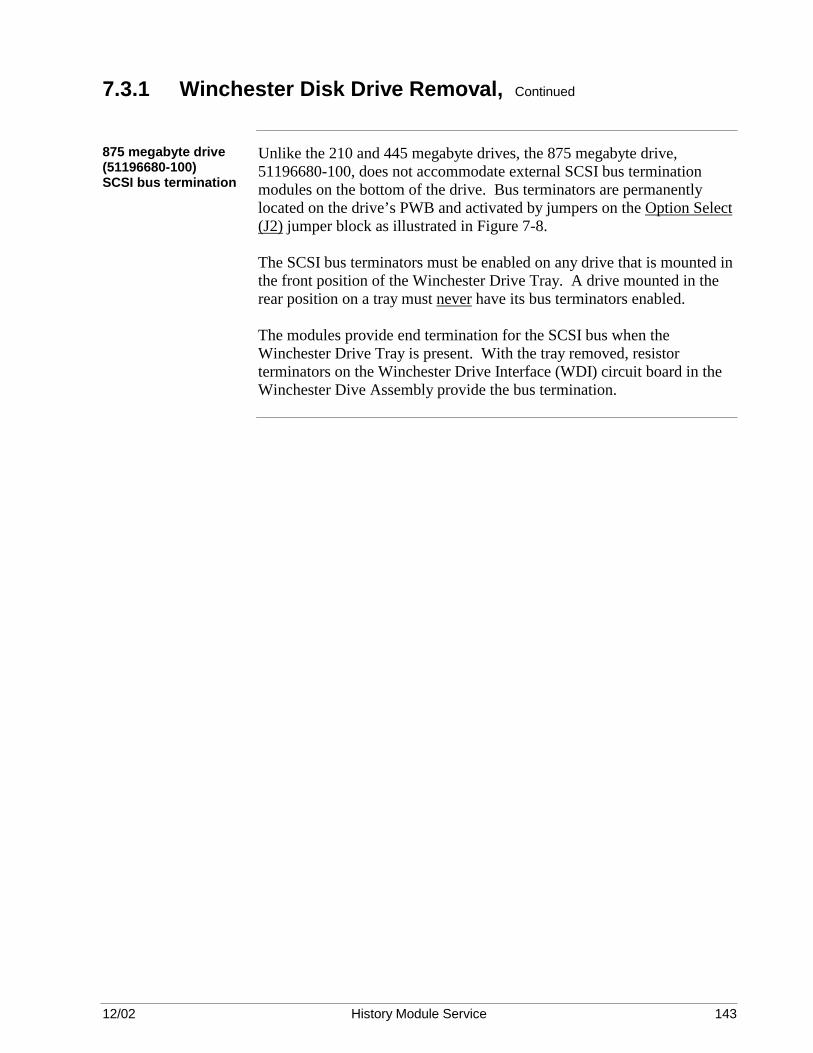
12/02 History Module Service 143
7.3.1 Winchester Disk Drive Removal, Continued
875 megabyte drive (51196680-100) SCSI bus termination
Unlike the 210 and 445 megabyte drives, the 875 megabyte drive, 51196680-100, does not accommodate external SCSI bus termination modules on the bottom of the drive. Bus terminators are permanently located on the drive’s PWB and activated by jumpers on the Option Select (J2) jumper block as illustrated in Figure 7-8. The SCSI bus terminators must be enabled on any drive that is mounted in the front position of the Winchester Drive Tray. A drive mounted in the rear position on a tray must never have its bus terminators enabled. The modules provide end termination for the SCSI bus when the Winchester Drive Tray is present. With the tray removed, resistor terminators on the Winchester Drive Interface (WDI) circuit board in the Winchester Dive Assembly provide the bus termination.

12/02 History Module Service 144
7.3.1 Winchester Disk Drive Removal, Continued
875 MB drive (51196680-200) jumper blocks
Figure 7-9 is an illustration of the 875 megabyte Winchester drive, 51196680-200, showing the locations of the two jumper blocks. The jumper blocks should be checked for proper positioning of the jumpers, based upon the drive’s mounting location on a tray. The two jumper blocks must be altered, if necessary, to accommodate the mounting location of the drive on either a right-hand or left-hand tray, front or rear position. These are the Option (J2) and SCSI Bus Address (J6) jumper blocks. Table 7-4 and Figure 7-9 illustrate the proper positioning of the jumpers on each jumper block for the drive’s mounting position. Table 7-4 875 MB Drive (51196680-200) SCSI Bus Address Selection
Drive Tray Location SCSI Bus Address Jumper Position
Left-Hand Rear 2 A1
Right-Hand Rear 3 A0 and A1
Left-Hand Front 4 A2
Right-Hand Front 5 * A0 and A2
* Replacement drives are shipped from the factory pinned for a SCSI device address of 5.
Continued on next page

12/02 History Module Service 145
7.3.1 Winchester Disk Drive Removal, Continued
875 megabyte drive (51196680-200) jumper block locations
The locations of the jumper blocks on the drive are illustrated in Figure 7-9. The Options (J2) and SCSI Address (J5) jumper blocks should be altered if necessary. SCSI drive addresses of 2, 3, 4, and 5 are the only valid addresses.
Figure 7-9 875 Megabyte Drive (51196680-200) Jumper Block Selections (Bottom View)
Drive A2 A1 A0
2
3
4
5
SCSI BusTerminationResistor Modules
(Pin 1)
SCSI Bus Address Jumper Block(See Address Selection Table)
DriveBottom
J6
PWB
DC PowerConnector
1 2 3 4
PWB
I/O Connector(J1)
+ 5 Vdc+ 5 Volts Return+12 Volts Return+12 Vdc
PWB
TE DS ME WP PD SS TP TP
J2
Option Jumper Block(Drives 2 and 3)
PWB
TE DS ME WP PD SS TP TP
J2
Option Jumper Block(Drives 4 and 5)
16725-B
Address Selection Table
A2A1A0
Continued on next page
12/02 History Module Service 146
7.3.1 Winchester Disk Drive Removal, Continued
875 megabyte drive (51196680-200) SCSI bus termination
Unlike the 210 and 445 megabyte drives, the 875 megabyte drive, 51196680-200, does not accommodate external SCSI bus termination modules on the bottom of the drive. Bus terminators are permanently located on the drive’s PWB and activated by jumpers on the Option (J2) jumper block as illustrated in Figure 7-9. The SCSI bus terminators must be enabled on any drive that is mounted in the front position of the Winchester Drive Tray. A drive mounted in the rear position on a tray must never have its bus terminators enabled. The modules provide end termination for the SCSI bus when the Winchester Drive Tray is present. With the tray removed, resistor terminators on the Winchester Drive Interface (WDI) circuit board in the Winchester Dive Assembly provide the bus termination.
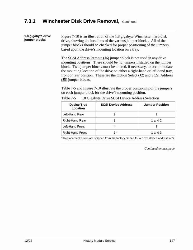
12/02 History Module Service 147
7.3.1 Winchester Disk Drive Removal, Continued
1.8 gigabyte drive jumper blocks
Figure 7-10 is an illustration of the 1.8 gigabyte Winchester hard-disk drive, showing the locations of the various jumper blocks. All of the jumper blocks should be checked for proper positioning of the jumpers, based upon the drive’s mounting location on a tray. The SCSI Address/Remote (J6) jumper block is not used in any drive mounting positions. There should be no jumpers installed on the jumper block. Two jumper blocks must be altered, if necessary, to accommodate the mounting location of the drive on either a right-hand or left-hand tray, front or rear position. These are the Option Select (J2) and SCSI Address (J5) jumper blocks. Table 7-5 and Figure 7-10 illustrate the proper positioning of the jumpers on each jumper block for the drive’s mounting position. Table 7-5 1.8 Gigabyte Drive SCSI Device Address Selection
Device Tray Location
SCSI Device Address Jumper Position
Left-Hand Rear 2 2
Right-Hand Rear 3 1 and 2
Left-Hand Front 4 3
Right-Hand Front 5 * 1 and 3
* Replacement drives are shipped from the factory pinned for a SCSI device address of 5.
Continued on next page

12/02 History Module Service 148
7.3.1 Winchester Disk Drive Removal, Continued
1.8 gigabyte drive jumper block locations
The locations of the jumper blocks on the drive are illustrated in Figure 7-10. Only the Options Select (J2) and SCSI Address (J6) jumper blocks should be altered. SCSI drive addresses of 2, 3, 4, and 5 are the only valid addresses.
Figure 7-10 1.8 Gigabyte Drive Jumper Block Selections (Bottom View)
Drive A2 A1 A0
2
3
4
5
SCSI BusTerminationResistor Modules
(Pin 1)
SCSI Bus Address Jumper Block(See Address Selection Table)
DriveBottom
J6
PWB
A2 A1 A0
DC PowerConnector
1 2 3 4
PWB
I/O Connector(J1)
+ 5 Vdc+ 5 Volts Return+12 Volts Return+12 Vdc
PWB
TE DS ME WP PD SS TP TP
J2
Option Jumper Block(Drives 2 and 3)
PWBTE DS ME WP PD SS TP TP
J2
Option Jumper Block(Drives 4 and 5)
16725-A
Address Selection Table
Continued on next page

12/02 History Module Service 149
7.3.1 Winchester Disk Drive Removal, Continued
1.8 gigabyte drive SCSI bus termination
Unlike the 210 megabyte and 445 megabyte drives, the 1.8 gigabyte drive does not accommodate external SCSI bus termination modules on the bottom of the drive. Bus terminators are permanently located on the drive’s PWB and activated by jumpers on the Option Select (J2) jumper block as illustrated in Figure 7-10. The SCSI bus terminators must be enabled on any drive that is mounted in the front position of the Winchester Drive Tray. A drive mounted in the rear position on a tray must never have its bus terminators enabled. The modules provide end termination for the SCSI bus when the Winchester Drive Tray is present. With the tray removed, resistor terminators on the Winchester Drive Interface (WDI) circuit board in the Winchester Dive Assembly provide the bus termination.

12/02 History Module Service 150

12/02 History Module Service 151
Section 8 – WDA History Module with Dual Logical Drive Tray Disassembly
8.1 Overview
Section contents The topics covered in this section are:
Topic See Page 8.1 Overview 153 8.2 History Module Disassembly 154 8.2.1 General Disassembly 155 8.2.2 Fan Assembly Removal 156 8.2.3 Power Supply Removal 156 8.2.4 Circuit Board Removal 157 8.2.5 Winchester Disk Assembly Removal 158 8.3 Winchester Drive Tray Disassembly 159 8.3.1 Winchester Disk Drive Removal 162
CAUTION CAUTION—Risk of electric shock
Purpose This section describes disassembly of the major components of the History
Module, including removal of the electronics boards, Winchester Disk Assembly, Winchester disk drive(s), power supply, fan assembly, and disconnection of the module cabling.
CAUTION CAUTION—Do not attempt any disassembly or repair the History Module without first conducting orderly testing and troubleshooting procedures. Return to Section 4 if you do not have a clear understanding of which part in the History Module has failed. YOU MUST OBTAIN OPERATOR PERMISSION BEFORE PLACING THE HISTORY MODULE OFF-LINE FOR TESTING.
Before disassembly Disassemble the major components of the History Module only to the
extent necessary to repair or replace a defective part. For a nonredundant drive system, always use the Universal Station to select the failed node from the History Module Status display and perform a SHUTDOWN command. For a redundant drive system, place the drive(s) off-line on the Winchester Drive Tray to be removed.
Continued on next page

12/02 History Module Service 152
8.1 Overview, Continued
Before proceeding Before proceeding:
IF the failure is in… SHUT DOWN, then go to …
The electronics and auxiliary components with a failure in the fan assembly, the power supply, or in a circuit board.
Subsection 8.2
The Winchester Disk Assembly with a failure of a drive, and the History Module is not configured for redundancy because only the right-hand Winchester Drive Tray exists.
Subsection 8.3
IF the failure is in…
DO NOT SHUT DOWN, but go to …
The Winchester Disk Assembly with a failure of a drive, and the History Module is configured for redundancy because both Winchester Drive Trays have one or two drives.
Subsection 8.3
Now go to the appropriate subsection for disassembly instructions.
8.2 History Module Disassembly
Overview Refer to the Five/Ten-Slot Module Service manual for any additional
disassembly procedure assistance. To protect the equipment from voltage transients and ensure reliable operation, always place the power supply ON/OFF switch in the OFF position before removing or replacing the circuit boards, power supply, fan assembly, cables, or the Winchester Disk Assembly. One or both Winchester Drive Trays can be removed while power is applied to the History Module because each has a power ON/OFF switch. Always follow proper ESD (Electrostatic Discharge) procedures when handling circuit boards or other electronic components.

12/02 History Module Service 153
8.2.1 General Disassembly
CAUTION CAUTION—Allow at least a 30-second drive spin-down time before attempting to remove a Winchester Drive tray. If a drive is jarred while its disks are spinning, there is “head crash” potential.
Preliminary Disassemble the module only to the extent necessary to repair or replace a
defective assembly or part. The item numbers referenced in this section are keyed to ballooned numbers in Figure 8-1. These item numbers are also used in Section 10, WDA Type History Module Assembly and Section 12, Spare Parts. Figure 3-1 is another view of the History Module assembly. Remove the front panel (1) by turning the two quarter-turn fasteners at the right side of the panel and swinging the panel outward until free from the chassis slots. Place the power switch on the power supply (2) in the OFF position and verify that all indicators on the power supply are extinguished.
Figure 8-1 WDA History Module Exploded View
6761
1
23
10
7
5
6
49
8
12
11
CAUTION CAUTION—Many of the assemblies used in this module are likely to contain electrostatically sensitive devices. Use a personnel grounding strap and grounded work surfaces/equipment. Store and transport parts only on electrostatically safe containers.

12/02 History Module Service 154
8.2.2 Fan Assembly Removal
Removal procedure Remove the fan assembly (3) by turning the two fasteners and sliding the
assembly out of the chassis. The individual fans are not a replaceable item, so the complete assembly must be replaced at the Optimum Replaceable Unit (ORU) level.
8.2.3 Power Supply Removal
Removal procedure Release the power supply (2) by simultaneously pulling outward on the
extractor levers located on each side of the assembly. Slide the power supply out of the History Module chassis after it has been released from its backpanel connectors. The circuit board in the power supply is not a replaceable item, so the complete assembly must be replaced if the board has failed.

12/02 History Module Service 155
8.2.4 Circuit Board Removal
Cable removal Disconnect those cables necessary for the removal of the associated circuit
board assembly. Three I/O circuit board assemblies have cables connected to them, the SPCII I/O (SPC2), WDI I/O (WDI), and LCN I/O (CLCN A/B).
SCSI bus ribbon cables
The SPCII I/O (SPC2) circuit board (8) and the WDI I/O (WDI) circuit board (9), located in slots 2 and 5, respectively, at the rear of the History Module chassis, are interconnected by two SCSI bus ribbon cables (10). The friction-fit connections are released by pulling outward on the individual connectors. Do not pull on the ribbon cable itself.
LCN coax cables The Local Control Network (LCN) trunk cables, A and B, connect to the
LCN I/O (CLCN A/B) circuit board (7) in slot 1 at the rear of the History Module chassis by coaxial T-connectors. Do not disconnect the cables from the T-connectors. Disconnect only the T-connectors from the board connectors. Removal of an LCN trunk cable connector from its T-connector interrupts the continuity of the network. Note where cables A and B connect. They are color-coded yellow (A) and green (B). Do not cross the cable connections.
K2LCN or K4LCN and SPC circuit boards
The K2LCN (11) or K4LCN (11) and SPC (12) circuit boards are removed by simultaneously pulling outward on the board extractors located on each side of the board and sliding the board out of the History Module chassis.
I/O circuit boards The I/O circuit boards, LCN I/O [CLCN A/B] (7) and SPCII I/O [SPC2]
(8), and the WDI I/O [WDI] (9), are located at the rear of the History Module chassis in the module’s I/O card cage. They are assigned to slots 1, 2, and 5, respectively. The circuit boards are removed by simultaneously pulling outward on the board extractors located on each side of the board and sliding the board out of the I/O card cage.

12/02 History Module Service 156
8.2.5 Winchester Disk Assembly Removal
Description The Winchester Disk Assembly (4) is composed of a chassis and two
Winchester Drive Trays, right-hand and optional left-hand, that reside in the chassis. The trays are interchangeable assemblies, but must be properly configured for their application in the History Module. Each tray is held in place by an extractor lever and by the friction of the tray’s mating connectors. The trays are removed from the assembly by pulling outward on their extractor lever and sliding the tray out of the chassis.
WDA removal The Winchester Disk Assembly is removed from the History Module
chassis by first removing two fasteners that are located towards the front of each side of the chassis. The Winchester Disk Assembly connectors mate with backpanel connectors in the slot 5 position, but are guided into position by the guide rails normally used for a circuit board in the slot 4 position. The friction of the backpanel connectors tends to hold the assembly in place. Assembly removal is initiated by first removing the fan assembly to gain access to the right side fastener. Both assembly fasteners are then removed, and the assembly is then pulled forward by grasping the metal partition dividing the tray compartments and sliding the assembly out of the History Module chassis along slot 4’s guide rails.
WDI circuit board replacement
Besides the Winchester Drive Trays, the Winchester Disk Assembly also contains the Winchester Drive Interface (WDI ) circuit board which is held in place by five Phillips-head screws, located at the corners and the forward center of the board, and available through access holes at the top of the assembly chassis. There is a spacer used with each fastener. The spacers are very important when mounting the circuit board, because without the spacers the circuit board will not mate properly with its backpanel connectors. Since it is very difficult to install the WDI circuit board using spacers, it is recommended that the circuit board not be replaced in the field. Instead, the Winchester Disk Assembly should be replaced if it is suspected that the circuit board has failed. The WDI circuit board cannot be ordered as a spare part.

12/02 History Module Service 157
8.3 Winchester Drive Tray Disassembly
Overview These instructions cover the disassembly of the right-hand or left-hand
Winchester Drive Tray and the removal of the Winchester disk drive(s) mounted on the tray. In a nonredundant History Module configuration, the left-hand Winchester Drive Tray will not be present. A Winchester Drive Tray can contain one (single drive) or two (dual) drives.
General You are probably removing a Winchester Drive Tray and replacing a drive
because you were informed by the History Module Status display that a DISKPROB exists. If you have redundant drives, be sure you request status from the Command Processor to verify the address of the failed drive, which is OFFLINE, and that its redundant partner is operational. Be sure both drives of a dual redundant configuration are OFFLINE.
Continued on next page

12/02 History Module Service 158
8.3 Winchester Drive Tray Disassembly, Continued
Before beginning disassembly
Before beginning disassembly, consider whether or not the History Module has redundant drives. If the module does not contain redundant drives, power can be removed from the drive(s) mounted on the right-hand Winchester Drive Tray, at the power supply or the tray by placing their respective power ON/OFF switch in the OFF position. Should the History Module contain redundant drives, then remove power only at the Winchester Drive Tray that contains the defective drive. Disassemble the Winchester Drive Tray only to the extent necessary to replace a defective part. The item numbers used in this subsection are keyed to ballooned numbers in Figures 8-2 and 8-3. Figure 8-2 Single-Drive Winchester Drive Tray Exploded View
Continued on next page

12/02 History Module Service 159
8.3 Winchester Drive Tray Disassembly, Continued
CAUTION CAUTION—The drive(s) mounted on the tray is an electrostatically sensitive device. Use a grounding strap and grounded work surfaces/equipment. Store and transport parts only in electrostatically safe containers.
Winchester Drive Tray description
The Winchester Drive Tray contains the following components: • One Winchester ST39175LW disk drive. • A ribbon cab le (3) that interconnects the drive(1) with the tray
connector (4) that interfaces to the WDI circuit board in the Winchester Disk Assembly. The ribbon cable provides the SCSI bus interface to the drive(s).
• A power ON/OFF switch (6) to control power from the power supply to
the drive(s) and SCSI bus terminators on the WDI circuit board in the Winchester Disk Assembly. When power is removed from the tray, SCSI bus terminators are activated on the WDI circuit board in anticipation of the loss of the bus terminators installed on a Winchester disk drive on the tray that is about to be removed. The terminators are installed on the drive that is mounted at the front of the tray.
• A tray power connector (7) that interfaces to the WDI circuit board in
the Winchester Disk Assembly and provides +5 Vdc, +12 Vdc, and ground return to the drive(s) from the power supply.
• An extractor lever (8) used to lock the tray in place in the Winchester
Disk Assembly and assist in extracting the tray when it is in place.
Termination The SCSI cable is terminated by a termination model attached to the drive end of the SCSI interface cable.
CAUTION CAUTION—When power is removed from a Winchester Drive Tray, the tray must be removed from the Winchester Disk Assembly as soon as possible because the SCSI bus terminators on the WDI circuit board in the Winchester Disk Assembly are electronically activated, which places them in parallel with the bus terminators installed on the drive. Intermittent errors could occur.

12/02 History Module Service 160
8.3.1 Winchester Disk Drive Removal
General When replacing a Winchester disk drive, it is important that you duplicate
all jumper block pinning on the drive. Of particular interest is the SCSI bus address (device) and terminator pinning. The replacement drive must be pinned identically. The drive has a self-locking protective mechanism that is activated when power is removed from the drive. However, the drive must be handled with great care.
Drive removal Gently place the tray in an inverted position prior to removal of the drive.
Loosen and remove the three Phillips-head screws on the bottom portion of the tray that attach the drive to the tray. Holding the drive in place on the tray, place the tray in an upright position. The power and SCSI printed flex-circuit connectors are friction-mated with their respective connectors on the drive. Separate the drive’s SCSI connector from ribbon cable SCSI connector by gently prying them apart using a small screwdriver or similar tool. The drive must be moved away from the printed flex-circuit SCSI connector to prevent damage to the printed flex-circuit. Do not attempt to move the printed flex-circuit SCSI connector away from the drive’s connector. Separate the power connector from its mating drive power connector. Do not pull on the power cable itself, but on the connector only. You can now remove the drive from the tray.

12/02 History Module Service 161
Section 9 – WREN Type History Module Assembly
9.1 Overview
Section contents The topics covered in this section are:
Topic See Page 9.1 Overview 163 9.2 Electronics Module Assembly 164 9.3 Winchester Drive Module Assembly 165 9.3.1 Fan Replacement 166 9.3.2 Power Supply Replacement 166 9.3.3 Disk Drive Replacement 166 9.3.4 Slide Tray Assembly 170 9.4 Nonredundant WREN III Drive Installation 171 9.4.1 Smart Peripheral Controller (SPC) and SPC I/O Boards 171 9.4.2 Single/Dual WREN III Drive Pinning 172 9.4.3 Single/Dual WREN III Drive Cabling 174 9.5 Nonredundant 210/445/875 MB and 1.8 GB Drive Installation 177 9.5.1 Smart Peripheral Controller (SPC) and SPC I/O Boards 178 9.5.2 Single/Dual 210 MB Drive Pinning 179 9.5.3 Single/Dual 445 MB Drive Pinning 184 9.5.4 Single/Dual 875 MB Drive Pinning 189 9.5.5 Single/Dual 1.8 GB Drive Pinning 195 9.5.6 Single/Dual 210/445/875 MB or 1.8 GB Drive Cabling 199 9.6 Redundant WREN III Drive Installation 204 9.6.1 Single Drive Installation 205 9.6.1.1 Single WREN III Drive Pinning 205 9.6.1.2 Single WREN III Drive Cabling 207 9.6.2 Dual Drive Installation 211 9.6.2.1 Dual WREN III Drive Pinning 211 9.6.2.2 Dual WREN III Drive Cabling 213 9.7 Redundant 210/445/875 MB or 1.8 GB Drive Installation 215 9.7.1 Redundant Single Drive Installation 215 9.7.1.1 Single 210 MB Drive Pinning 215 9.7.1.2 Single 445 MB Drive Pinning 219 9.7.1.3 Single 875 MB Drive Pinning 222 9.7.1.4 Single 1.8 GB Drive Pinning 228 9.7.1.5 Single 210/445/875 MB or 1.8 GB Drive Cabling 231 9.7.2 Redundant Dual Drive Installation 234 9.7.2.1 Dual 210 MB Drive Pinning 234 9.7.2.2 Dual 445 MB Drive Pinning 238 9.7.2.3 Dual 875 MB Drive Pinning 242 9.7.2.4 Dual 1.8 GB Drive Pinning 249 9.7.2.5 Dual 210/445/875 MB or 1.8 GB Drive Cabling 253
Purpose This section describes the assembly of the History Module with major
components that includes the circuit boards, Winchester disk drive(s), power supply, fan assembly, and the module cabling.

12/02 History Module Service 162
9.2 Electronics Module Assembly
Reference Assembly of the electronics module is described in the Five/Ten-Slot
Module Service or the Dual Node Service manual.
CAUTION CAUTION—Always follow proper ESD (Electrostatic Discharge) procedures when handling circuit boards and other electronic components.
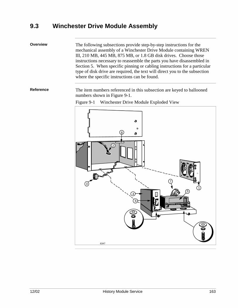
12/02 History Module Service 163
9.3 Winchester Drive Module Assembly
Overview The following subsections provide step-by-step instructions for the
mechanical assembly of a Winchester Drive Module containing WREN III, 210 MB, 445 MB, 875 MB, or 1.8 GB disk drives. Choose those instructions necessary to reassemble the parts you have disassembled in Section 5. When specific pinning or cabling instructions for a particular type of disk drive are required, the text will direct you to the subsection where the specific instructions can be found.
Reference The item numbers referenced in this subsection are keyed to ballooned
numbers shown in Figure 9-1. Figure 9-1 Winchester Drive Module Exploded View
51
6
4
3
2
8
7
6347

12/02 History Module Service 164
9.3.1 Fan Replacement
Procedure Slide the fan assembly (1) into the chassis, being careful that the connector at the rear of the unit mates correctly, and secure the assembly with the two bale-headed fasteners.
9.3.2 Power Supply Replacement
Procedure Use the following procedure to install the drive power supply on the tray
assembly. 1. Attach the power supply (4) to the tray assembly with four M4 x 12
mm screws, four M4 lock washers, and four M4 wide washers as shown in the inset illustration in Figure 9-1.
2. Install the wires previously removed from the power supply’s terminal block (6) in subsection 5.3. Reconnect the AC power cord (2).
9.3.3 Disk Drive Replacement
Drive pinning and bus termination
Prepare the disk drive for installation by pinning, and if necessary, installing a data bus terminator resistor module (WREN III drive) or termination resistor modules (210 MB or 445 MB drives) on the replacement drive as required. For assistance, refer to the subsection that has installation instructions for the particular type of drive. • See subsection 9.3 for nonredundant WREN III drive information
(pinning information is in subsection 9.3.2). • See subsection 9.4 for nonredundant 210 MB, 445 MB, 875 MB, or 1.8
GB drive information (pinning information is in subsection 9.4.2 or 9.4.3).
• See subsection 9.5 for redundant WREN III drive information
(redundant single drive pinning information is in subsection 9.5.1, redundant dual drive pinning information is in subsection 9.5.2).
• See subsection 9.6 for redundant 210 MB, 445 MB, 875 MB, or 1.8 GB
disk drive information (redundant single drive information is in subsection 9.6.1, redundant dual drive information is in subsection 9.6.2).
Continued on next page

12/02 History Module Service 165
9.3.3 Disk Drive Replacement, Continued
WREN III drive mounting
The WREN III drive requires rubber shock-mounts. If they appear nonresilient or cracked, replacement shock-mounts (Honeywell part number 51108679-100) are recommended. Use either new mounts or salvage the mounts from the failed drive. Attach them to the slide-out tray assembly as illustrated in Figure 9-2. Orient the drive as illustrated in Figure 9-1 and secure it with four #6-32 x 1 1/4 inch panhead screws, four #6 split lock washers, and four M3.5 wide washers as illustrated in Figure 9-2. Connect the dc power cable to the disk drive. Figure 9-2 Assembly of Drive Shock Mount Hardware
51108679-300 Snub Collar
51108679-200 Snub Washer
3.5 x 10 (2)
51108679-100 Shock Mount
51108679-200
3.5 w/Flat
3.5 Hex (2)3.5 w/Flat
#6 Split Lock
6-32 x 1.25 2090
Continued on next page

12/02 History Module Service 166
9.3.3 Disk Drive Replacement, Continued
210/445/875 MB and 1.8 GB Drive mounting
The 210 MB, 445 MB, 875 MB, and 1.8 GB drive requires an adapter plate to mount the drive on the tray assembly. The drive is orientated with its connectors to the right side of the tray assembly. No shock-mounts are required. Figure 9-3 illustrates the attachment of the adapter plate to the drive. Three 6 - 32 1/4-inch screws are used to attach the plate. Figure 9-4 illustrates the mounting of the drive adapter plate on the tray assembly. Four M3.5 x 10 mm screws and four flat washers are used in the process. Figure 9-3 Assembly of Adapter Plate to Drive
Rear Side of Drive(Connector Side)
Adapter Plate
6 - 32 1/4 Inch Screws 11838
Continued on next page

12/02 History Module Service 167
9.3.3 Disk Drive Replacement, Continued
Drive mounting
Figure 9-4 Mounting the 210/445/875 MB or 1.8 GB Drive on the Tray Assembly
3.5 x 10 mm Machine Screw (51108385-410)
1. Set the tray assembly on its side with the drive power supply at the bottom. 2. Mount the drive adapter plate using the screws and washers provided. Ensure that no washers fall into the power supply by covering it with a protective material.
Drive Adapter Plate (51196226-100)
Notes:
Tray Assembly
3.5 mm Flat Washer
(51108390-004)
Self-Locking PEM Nut on Plate
Original Shock Mount Hole in Assembly
11839

12/02 History Module Service 168
9.3.4 Slide Tray Assembly
Procedure Use the following procedure to reassemble the slide-out tray assembly.
1. Insert the slide tray assembly into the chassis until about 15
centimeters (6 inches) of the tray assembly protruding. Reconnect and dress the ribbon cable(s) as they were originally installed and secure them in place with the cable clamp(s) on the slide tray assembly and/or the inside surface of the module chassis. Be sure the ribbon cable is secured properly and will not interfere with the fan assembly’s operation. Section 7 details the proper cable dress for the appropriate drive configuration.
2. Carefully slide the tray assembly into the module, using special care not to pinch the ribbon cable(s) or bind a ribbon cable between the slide tray assembly and the back surface of the module. Secure the tray assembly in position by locking the two quarter-turn fasteners at the front of the tray assembly.
Secure the ribbon cable with the cable clamp(s) exterior to the module chassis. If you have released the ribbon cable from the clamp at the top of the I/O card cage, dress the cable and secure it with the cable clamp(s).
3. Reconnect the power supply’s ac power cord (2) to the power supply assembly. Connect the fan assembly’s power cable to its mating connector that is located on the tray assembly at the front of the power supply.
4. Insert the front cover’s tabs into the slots in the chassis and secure the front cover with the two quarter-turn fasteners.
You can now refer to the History Module startup instructions in Section 9. If you have replaced a redundant drive, be sure to synchronize the drives as instructed in subsection 9.4.

12/02 History Module Service 169
9.4 Nonredundant WREN III Drive Installation
Overview Use the supplementary information provided in this subsection when
installing a nonredundant WREN III drive and associated components.
9.4.1 Smart Peripheral Controller (SPC) and SPC I/O Boards
SPC Pinning Check the pinning jumpers in location TS1 on the Smart Peripheral
Controller circuit board (51401052-100) and verify they are positioned as illustrated in Figure 9-5. The revision pinning in TS2 is factory set and must not be altered in the field. Figure 9-5 SPC Board Address Pinning for SCSI Bus Address
TS2TS1
Board Revision Socket DO NOT CHANGE
Program TS1 as follows: PINS DESCRIPTION 9-8 Always Shorted 10-7 Always Shorted 11-6 Always Shorted 12-5 Always Shorted 13-4 Short = WREN III (History Module)* 14-3 Open** 15-2 Open** 16-1 Open** * = Setting for this application ** = SCSI Address 7 for this application
SPC51401052-100
ADDR REV
910111213141516
87654321
3814
No SPC I/O pinning required
The SPC Input/Output (SPC I/O) circuit board (51304156-100) that interfaces WREN III drives has no pinning requirements.

12/02 History Module Service 170
9.4.2 Single/Dual WREN III Drive Pinning
Overview Refer to Figures 9-6 and 9-7 to determine pinning for the nonredundant
WREN III drive(s).
Single drive pinning In a nonredundant single drive configuration, a single WREN III drive is
mounted in one Winchester Drive Module. As illustrated in Figure 9-6, the single drive is designated “Drive 5” and has a SCSI bus address of 5. Address 5 is selected on the drive by placing Drive Select Plugs in the “2” and “0” positions. In binary arithmetic, 22 + 20 = 4 + 1 = 5 decimal. Be sure that a terminator resistor module is installed on the drive. Jumpers must also be installed in the locations marked P (Parity Checking) and TP (Termination Power).
Figure 9-6 Single WREN III Drive Configuration and Termination (Nonredundant)
16763
Drive 5 Rear View Single Drive (Nonredundant)
2,1,0 = Octal address on SCSI Bus P = Parity Checking TP = Termination Power
Set Jumpers as Shown for Correct System Address
Address 5
Drive Select Jumpers
Terminator
2 1 0 P TP
Continued on next page

12/02 History Module Service 171
9.4.2 Single/Dual WREN III Drive Pinning, Continued
Dual WREN III drive pinning
In a nonredundant dual drive configuration, the two WREN III drives are housed in separate Winchester Drive Modules. As illustrated in Figure 9-7, Drive 5 is mounted in the upper module (module #2) and has a SCSI bus address of 5. Address 5 is selected by placing Drive Select Plugs in the “2” and “0” positions. In binary arithmetic, 22 + 20 = 4 + 1 = 5 decimal. Be sure that a terminator resistor module is installed on the drive. The second drive, Drive 3, is mounted in the lower module (module #1) and has a SCSI bus address of 3. Address 3 is selected by placing Drive Select Plugs in the “1” and “0” positions. In binary arithmetic, 21 + 20 = 2 + 1 = 3 decimal. Be sure that the terminator resistor module is removed from the drive. In the dual drive configuration, the SCSI bus cable from the SPC I/O card connects first to Drive 3 and then to Drive 5. For this reason, no terminator resistor module should be installed on Drive 3. The termination must be located at the end of the SCSI bus cable on Drive 5. Each drive must also have a jumper in the locations marked P (Parity Checking) and TP (Termination Power).
Figure 9-7 Dual WREN III Drive Configuration and Termination (Nonredundant)
16764
Rear View Dual Drive 5 (Nonredundant)Drive ADrive 5
Address 5 2 1 0 P TP
Remove Terminator from Drive 3
Address 3 2 1 0 P TP
Rear View Dual Drive 3 (Nonredundant)
Drive ADrive 3
2,1,0 = Octal Address on SCSI Bus P = Parity Checking TP = Termination Power
Set Jumpers as Shown for Correct System Address
Drive Select Jumpers
Keep Terminator in Drive 5

12/02 History Module Service 172
9.4.3 Single/Dual WREN III Drive Cabling
Overview The single SCSI bus ribbon cable from the SPC I/O circuit board in the I/O card cage on the electronics module passes through a slotted hole in the back of the Winchester Drive Module above the electronics module and routes over the slide tray assembly to the drive. If it is a single drive History Module, the cable ends at the drive. If it is a dual drive History Module, the cable exits the lower Winchester Drive Module (module #1) and then enters the upper Winchester Drive Module (module #2) where it connects to the drive in the module. The SCSI bus cable always connects to a WREN III drive with the red stripe at the right side of the drive as you face the connectors on the drive.
Avoid the fan blades Use special care to prevent the ribbon cables from interfering with the
rotating fan blades in the fan assembly. The cable can be placed under the WREN III drive to avoid the fan blades. Note that the cable is folded under the drive so it can make a 90° turn up to the drive connector.
Single drive cabling Figures 9-8 (side view) and 9-9 (top and front view) show the cable
routing for a single WREN III drive. The drive must have a terminator resistor module installed on it to terminate the end of the SCSI bus cable. Figure 9-8 SCSI Cable Routing for Single WREN III Drive
16765
Slide Tray Assembly
Winchester Drive Module
WREN III Drive 5 SCSI Bus
Ribbon Cable
Electronics Module
SIDE VIEW
SPC I/O Connector
Terminator Resistor Module
Continued on next page

12/02 History Module Service 173
9.4.3 Single/Dual WREN III Drive Cabling, Continued
Single WREN III drive SCSI cable installation
Figure 9-9 Single WREN III Drive SCSI Cable Installation
Red Line
Winchester Drive 5
Top View of Chassis
Locate Approximately as Shown
Red Line
Electronics Module (Shown for Reference)
I/O Card Cage
Continued on next page

12/02 History Module Service 174
9.4.3 Single/Dual WREN III Drive Cabling, Continued
Dual drive cabling Figure 9-10 illustrates a side view of the cable routing for dual WREN III
drives. Note the cabling is similar to single drive cabling, but the cable continues on to the upper Winchester Drive Module (module #2) that contains the second WREN III drive. The cable is folded and routed under the drives in the same manner that is illustrated in Figure 9-9. Note the upper module contains Drive 5, while the lower module contains Drive 3. The drive in the upper module must have a terminator resistor module installed on it to terminate one end of the SCSI bus cable.
Figure 9-10 SCSI Cable Routing for Dual WREN III Drives
16767
Slide Tray Assembly
Slide Tray Assembly
Winchester Drive Module #2
Winchester Drive Module #1
Electronics Module
WREN III Drive 5
WREN III Drive 5
SIDE VIEW
SCSI Bus Ribbon Cable
SPC I/O Connector
Terminator Resistor Module

12/02 History Module Service 175
9.5 Nonredundant 210/445/875 MB and 1.8 GB Drive Installation
Overview Use the supplementary information in this section when installing either
the 210 megabyte, 445 megabyte, 875 megabyte, or 1.8 gigabyte drive and associated components. With the exception of drive pinning instructions, the installation of either type of drive is identical.

12/02 History Module Service 176
9.5.1 Smart Peripheral Controller (SPC) and SPC I/O Boards
SPC pinning Check the pinning jumpers at location TS1 on the Smart Peripheral
Controller circuit board (51401052-100) and verify they are positioned as illustrated in Figure 9-11. The revision pinning at TS2 is factory set and must not be altered in the field.
SPC firmware revision Inspect the Smart Peripheral Controller circuit board and verify that it has
the proper firmware revision. It must be revision “G,” or a later revision. The two firmware EPROMs are located approximately at coordinates 18F and 18G as illustrated in Figure 9-11. If replacement of the firmware is required, note the orientation and location of the EPROMs 0928-101 and 0928-102 before removal. Be sure to wear an ESD wriststrap that is properly grounded. Remove the EPROMs and replace them with the proper revision. Change the firmware revision at the front of the circuit board.
No SPC I/O pinning required
The SPC Input/Output (SPC I/O) circuit board (51304156-100) that interfaces the 210 MB, 445 MB, 875 MB, or 1.8 GB drive has no pinning requirements. Figure 9-11 SPC Board Address Pinning for SCSI Bus Address
TS2TS1
Board Revision Socket DO NOT CHANGE
Program TS1 as follows: PINS DESCRIPTION 9-8 Always Shorted 10-7 Always Shorted 11-6 Always Shorted 12-5 Always Shorted 13-4 Short = WREN III (History Module)* 14-3 Open** 15-2 Open** 16-1 Open** * = Setting for this application ** = SCSI Address 7 for this application
SPC51401052-100
ADDR REV
910111213141516
87654321
12544

12/02 History Module Service 177
9.5.2 Single/Dual 210 MB Drive Pinning
Overview Use Figures 9-12 and 9-14 to determine the pinning for the nonredundant
210 MB drive(s).
Single drive pinning In a nonredundant single drive configuration, a single 210 MB drive is
mounted in the front position on the tray assembly in one Winchester Drive Module. Figure 9-12 illustrates the location and configuration of the jumper blocks on the 210 MB drive. The drive must be configured for a SCSI bus address of 5. Also, note the location of the jumpers on the Active/Passive Termination, Terminator Power, and Parity/Remote Start jumper blocks. The SCSI Drive Address jumper block must have jumpers between pins 1 and 2, and pins 5 and 6 for correct addressing. The Active/Passive Termination jumper block must have jumpers between pins 2 and 4, and pins 5 and 6 because SCSI bus termination resistor modules must be installed on the Winchester disk drive. The Terminator Power jumper block must have jumper between pins 1 and 2 because SCSI bus termination resistor modules must be installed on the Winchester disk drive. The Parity/Remote Start jumper block must have a jumper between pins 1 and 2 to enable data parity checking. Terminator resistor modules must be installed on the drive as illustrated in Figure 9-13.
Continued on next page

12/02 History Module Service 178
9.5.2 Single/Dual 210 MB Drive Pinning, Continued
Terminated 210 MB Drive 5 jumper block selections
Figure 9-12 Terminated 210 MB Drive 5 Jumper Block Selections (Bottom View)
5 3 1 6 4 2
Termination Resistor Modules
(Pin 1)
Parity/Remote Start Jumper Block
PWB
3 1 4 2
Options Jumper Block (None Selected for Drives 2-5)
PWB
Active/Passive Termination Jumper Block
PWB
Ground Signal
Terminator Power Jumper Block
PWB3 1 4 2
SCSI Drive Address Jumper Block PWB
Ground Signal
2 4 6 1 3 5
I/O Connector
9 7 10 8
5 3 6 4
1 2
13 11 14 12
Pin 1
DC Power ConnectorPWB
+ 5 Vdc + 5 Volts Return + 12 Volts Return + 12 Vdc
1 2 3 4
Drive 5
Drive 5
Drive 5
Drive 5
51196220-100
11837
Continued on next page

12/02 History Module Service 179
9.5.2 Single/Dual 210 MB Drive Pinning, Continued
210 MB drive terminator modules
Figure 9-13 Bottom View of 210 MB Drive with SCSI Bus Terminator Modules Installed
6762
Pin 1 Dot or Part Number on Top Side
Square Pad on PWB Indicates Pin 1
Continued on next page

12/02 History Module Service 180
9.5.2 Single/Dual 210 MB Drive Pinning, Continued
Dual drive pinning In a dual drive configuration, two 210 MB drives can be housed in
separate Winchester Drive Modules or the same module. Drive 5 is mounted in the front position on the tray assembly in the upper module (module #2), or the only module, and has a SCSI bus address of 5. Figure 9-12 illustrates the location and configuration of the jumper blocks on Drive 5. Use the single drive pinning instructions to properly configure the drive. Termination resistor modules must be installed on Drive 5 as illustrated in Figure 9-13. The second drive, Drive 3, is mounted in the front position on the tray assembly in the lower module (module #1), if there are two modules, or the rear position, if there is a single module, and has a SCSI bus address of 3. Also, note the location of the jumpers on the Active/Passive Termination jumper block. Figure 9-14 illustrates the location and configuration of the jumper blocks on Drive 3. The SCSI Drive Address jumper block must have jumpers between pins 3 and 4, and pins 5 and 6 for correct addressing. The Active/Passive Termination jumper block must have no jumpers because no SCSI bus termination resistor modules should be installed on the drive. The Terminator Power jumper block must have a jumper between pins 2 and 4 because no SCSI bus termination resistor modules should be installed on the Winchester disk drive. The Parity/Remote Start jumper block must have a jumper between pins 1 and 2 to enable data parity checking. Be sure that the terminator resistor modules are removed from Drive 3. In the nonredundant dual drive configuration, the SCSI bus cable from the SPC I/O circuit board connects first to Drive 3 and then to Drive 5. For this reason, no termination resistor modules should be installed on Drive 3. They must be at the end of the SCSI bus cable on Drive 5.
Continued on next page

12/02 History Module Service 181
9.5.2 Single/Dual 210 MB Drive Pinning, Continued
Nonterminated 210 MB Drive 3 jumper block selections
Figure 9-14 Nonterminated 210 MB Drive 3 Jumper Block Selections (Bottom View)
2 4 6 1 3 5
No Termination Resistor Modules
Parity/Remote Start Jumper Block
PWB
3 1 4 2
Options Jumper Block (None Selected for Drives 2-5)
PWB
Active/Passive Termination Jumper Block
PWB
Ground Signal
Terminator Power Jumper Block
PWB
SCSI Drive Address Jumper Block PWB
Ground Signal
I/O Connector
9 7 10 8
5 3 6 4
1 2
13 11 14 12
Pin 1
DC Power ConnectorPWB
+ 5 Vdc + 5 Volts Return + 12 Volts Return + 12 Vdc
1 2 3 4
Drive 3
3 1 4 2
Drive 3
5 3 1 6 4 2
Drive 3
(No Jumpers)
Drive 3
51196220-100
11843

12/02 History Module Service 182
9.5.3 Single/Dual 445 MB Drive Pinning
Overview Use Figures 9-15 and 9-17 to determine the pinning for the nonredundant
445 MB drive(s).
Single drive pinning In a nonredundant single drive configuration, a single 445 MB drive is
mounted in the front position on the tray assembly in one Winchester Drive Module. Figure 9-15 illustrates the location and configuration of the jumper blocks on the 445 MB drive. The drive must be configured for a SCSI bus address of 5. Also, note the location of the jumpers on the Active/Passive Termination jumper block. The SCSI Drive Address jumper block must have jumpers in positions 1 and 3 for correct addressing. The Active/Passive Termination jumper block must have a jumper in position 5 to enable data parity checking, and a jumper between positions 7 and 8 because SCSI bus termination resistor modules must be installed on the drive. The Options jumper block should have no jumpers installed on it. Terminator resistor modules must be installed on the drive as illustrated in Figure 9-16.
Continued on next page

12/02 History Module Service 183
9.5.3 Single/Dual 445 MB Drive Pinning, Continued
Terminated 445 MB Drive 5 jumper block selections
Figure 9-15 Terminated 445 MB Drive 5 Jumper Block Selections (Bottom View)
Options Jumper Block (Not Used – No Jumpers)
1 2 3 4 5 6
Active/Passive Termination Jumper Block
1 2 3 4 5 6 7 8
SCSI Drive Address Jumper Block
3 2 1
DC Power Connector
+ + + +
5 Vdc 5 Volts Return 12 Volts Return 12 Vdc
1 2 3 4
PWB
PWB
PWB
PWB
Drive Bottom
Drive Bottom
SCSI BusTermination Resistor Modules
(Pin 1)
12507-A
Continued on next page

12/02 History Module Service 184
9.5.3 Single/Dual 445 MB Drive Pinning, Continued
445 MB drive with terminator modules
Figure 9-16 Bottom View of 445 MB Drive with SCSI Bus Terminator Modules Installed
12492
Pin 1 Dot or Part Number on
Top
Continued on next page

12/02 History Module Service 185
9.5.3 Single/Dual 445 MB Drive Pinning, Continued
Dual drive pinning In a dual drive configuration, two 445 MB drives can be housed in
separate Winchester Drive Modules or the same module. Drive 5 is mounted in the front position on the tray assembly in the upper module (module #2), or the only module, and has a SCSI bus address of 5. Figure 9-15 illustrates the location and configuration of the jumper blocks on Drive 5. Use the single drive pinning instructions to properly configure the drive. Termination resistor modules must be installed on Drive 5 as illustrated in Figure 9-16. The second drive, Drive 3, is mounted in the front position on the tray assembly in the lower module (module #1), if there are two modules, or the rear position, if there is a single module, and has a SCSI bus address of 3. Also, note the location of the jumpers on the Active/Passive Termination jumper block. Figure 9-17 illustrates the location and configuration of the jumper blocks on Drive 3. The SCSI Drive Address jumper block must have jumpers installed in positions 1 and 2 for correct addressing. The Active/Passive Termination jumper block must have a jumper installed in position 5 to enable data parity checking. No SCSI bus termination resistor modules should be installed on the drive. The Options jumper block should have no jumpers installed on it. Be sure that the terminator resistor modules are removed from Drive 3. In the nonredundant dual drive configuration, the SCSI bus cable from the SPC I/O circuit board connects first to Drive 3 and then to Drive 5. For this reason, no termination resistor modules should be installed on Drive 3. They must be at the end of the SCSI bus cable on Drive 5.
Continued on next page

12/02 History Module Service 186
9.5.3 Single/Dual 445 MB Drive Pinning, Continued
Nonterminated 445 MB Drive 3 jumper block selections
Figure 9-17 Nonterminated 445 MB Drive 3 Jumper Block Selections (Bottom View)
Options Jumper Block (Not Used – No Jumpers)
1 2 3 4 5 6
Active/Passive Termination Jumper Block
1 2 3 4 5 6 7 8
SCSI Drive Address Jumper Block
3 2 1
DC Power Connector
+ + + +
5 Vdc 5 Volts Return 12 Volts Return 12 Vdc
1 2 3 4
PWB
PWB
PWB
PWB
Drive Bottom
Drive Bottom
12503-A
No SCSI BusTermination Resistor Modules

12/02 History Module Service 187
9.5.4 Single/Dual 875 MB Drive Pinning
Overview Use Figures 9-18 through 9-21 to determine the pinning for the
nonredundant 875 MB drive(s).
ATTENTION ATTENTION—Your History Module will contain one of two types of 875 megabyte drives. They are easily identified by their appearance and the Honeywell part number (51196680-100 or 51196680-200) on the drive. Be sure that you use the pinning procedure that matches the drive.
Single drive In a nonredundant single drive configuration, a single 875 MB drive is
mounted in the front position on the tray assembly in one Winchester Drive Module.
875 MB Drive 5 (51196680-100)
Figure 9-18 illustrates the location and configuration of the jumper blocks on the 875 MB drive, 51196680-100. The drive must be configured for a SCSI bus address of 5 on the SCSI Address (J5) jumper block. Also, note the location of the jumper(s) on the Option Select (J2) jumper block. The SCSI Address (J5) jumper block must have jumpers in positions 1 and 3 for correct addressing. The Option Select (J2) jumper block must have a jumper in position 5 to enable data parity checking, a jumper in position 1 to enable the SCSI bus terminators on the drive, and a jumper between positions 7 and 8 to enable power from the SCSI bus for the bus terminators. The SCSI Address/Remote (J6) jumper block must have no jumpers installed on it.
Continued on next page

12/02 History Module Service 188
9.5.4 Single/Dual 875 MB Drive Pinning, Continued
Terminated 875 MB Drive 5 jumper block selections (51196680-100)
Figure 9-18 Terminated 875 MB Drive 5 (51196680-100) Jumper Block Selections (Bottom View)
Option Select Jumper BlockPWB
SCSI Address/Remote Jumper Block (Not Used – No Jumpers)
1 2 3 4 5 6Drive
Bottom
J6
J2
DC Power Connector
+ + + +
5 Vdc 5 Volts Return 12 Volts Return 12 Vdc
1 2 3 4
PWB
PWB
SCSI Drive Address Jumper Block
PWB
Drive Bottom3 2 1
J1
54020
J5J1
87654321
Continued on next page
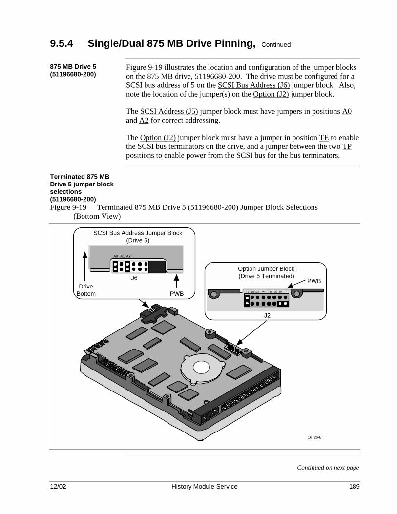
12/02 History Module Service 189
9.5.4 Single/Dual 875 MB Drive Pinning, Continued
875 MB Drive 5 (51196680-200)
Figure 9-19 illustrates the location and configuration of the jumper blocks on the 875 MB drive, 51196680-200. The drive must be configured for a SCSI bus address of 5 on the SCSI Bus Address (J6) jumper block. Also, note the location of the jumper(s) on the Option (J2) jumper block.
The SCSI Address (J5) jumper block must have jumpers in positions A0 and A2 for correct addressing.
The Option (J2) jumper block must have a jumper in position TE to enable the SCSI bus terminators on the drive, and a jumper between the two TP positions to enable power from the SCSI bus for the bus terminators.
Terminated 875 MB Drive 5 jumper block selections (51196680-200)
Figure 9-19 Terminated 875 MB Drive 5 (51196680-200) Jumper Block Selections (Bottom View)
SCSI BusTerminationResistor Modules
(Pin 1)
16726-B
PWBTE DS ME WP PD SS TP TP
J2
Option Jumper Block(Drive 5 Terminated)
SCSI Bus Address Jumper Block(Drive 5)
DriveBottom
J6
PWB
A2A1A0
Continued on next page

12/02 History Module Service 190
9.5.4 Single/Dual 875 MB Drive Pinning, Continued
Dual drives In a dual drive configuration, two 875 MB drives can be housed in
separate Winchester Drive Modules or the same module. The first drive, Drive 5 is mounted in the front position on the tray assembly in the upper module (module #2), or the only module, and has a SCSI bus address of 5. Figure 9-18 or 9-19 illustrates the location and configuration of the jumper blocks on Drive 5. Use the single drive pinning instructions to properly configure the drive. The second drive, Drive 3, is mounted in the front position on the tray assembly in the lower module (module #1), if there are two modules, or the rear position, if there is a single module, and has a SCSI bus address of 3.
875 MB Drive 3 (51196680-100)
Figure 9-20 illustrates the location and configuration of the jumper blocks on Drive 3, 51196680-100. The drive must be configured for a SCSI bus address of 3 on the SCSI Address (J5) jumper block. Also, note the location of the jumper(s) on the Option Select (J2) jumper block. The SCSI Address (J5) jumper block must have jumpers installed in positions 1 and 2 for correct addressing. The Option Select (J2) jumper block must have a jumper installed in position 5 to enable data parity checking. The SCSI Address/Remote (J6) jumper block must have no jumpers installed on it. In the nonredundant dual drive configuration, the SCSI bus cable from the SPC I/O circuit board connects first to Drive 3 and then to Drive 5. For this reason, the SCSI bus terminators on Drive 3 must not be enabled. Only the SCSI bus terminators on Drive 5 must be enabled.
Continued on next page

12/02 History Module Service 191
9.5.4 Single/Dual 875 MB Drive Pinning, Continued
Nonterminated 875 MB Drive 3 jumper block selections (51196680-100)
Figure 9-20 Nonterminated 875 MB Drive 3 (51196680-100) Jumper Block Selections (Bottom View)
Option Select Jumper BlockPWB
SCSI Address/Remote Jumper Block (Not Used – No Jumpers)
1 2 3 4 5 6Drive
Bottom
J6
J2
DC Power Connector
+ + + +
5 Vdc 5 Volts Return 12 Volts Return 12 Vdc
1 2 3 4
PWB
PWB
SCSI Drive Address Jumper Block
PWB
Drive Bottom3 2 1
J1
54027
J5J1
87654321
875 MB Drive 3 (51196680-200)
Figure 9-21 illustrates the location and configuration of the jumper blocks on Drive 3, 51196680-200. The drive must be configured for a SCSI bus address of 3 on the SCSI Bus Address (J6) jumper block. Also, note the absence of the jumpers on the Option (J2) jumper block. The SCSI Address (J5) jumper block must have jumpers installed in positions A0 and A1 for correct addressing. The Option Select (J2) jumper block must have no jumpers installed on it. In the nonredundant dual drive configuration, the SCSI bus cable from the SPC I/O circuit board connects first to Drive 3 and then to Drive 5. For this reason, the SCSI bus terminators on Drive 3 must not be enabled. Only the SCSI bus terminators on Drive 5 must be enabled.

12/02 History Module Service 192
9.5.4 Single/Dual 875 MB Drive Pinning, Continued
Nonterminated 875 MB Drive 3 jumper block selections (51196680-200)
Figure 9-21 Nonterminated 875 MB Drive 3 (51196680-200) Jumper Block Selections (Bottom View)
SCSI BusTerminationResistor Modules
(Pin 1)
16730-B
SCSI Bus Address Jumper Block(Drive 3)
DriveBottom
J6
PWB
PWB
TE DS ME WP PD SS TP TP
J2
Option Jumper Block(Drive 3 Nonterminated)
A2A1A0

12/02 History Module Service 193
9.5.5 Single/Dual 1.8 GB Drive Pinning
Overview Use Figures 9-22 and 9-23 to determine the pinning for the nonredundant
1.8 GB drive(s).
Single drive pinning In a nonredundant single drive configuration, a single 1.8 GB drive is
mounted in the front position on the tray assembly in one Winchester Drive Module. Figure 9-22 illustrates the location and configuration of the jumper blocks on the 1.8 GB drive. The drive must be configured for a SCSI bus address of 5 on the SCSI Bus Address (J6) jumper block. Also, note the location of the jumpers on the Option (J2) jumper block. The SCSI Address (J6) jumper block must have jumpers in positions A0 and A2 for correct addressing. The Option Select (J2) jumper block must have a jumper in position TE to enable the SCSI bus terminators on the drive, and a jumper between the two TP positions to enable power from the SCSI bus for the bus terminators.
Continued on next page

12/02 History Module Service 194
9.5.5 Single/Dual 1.8 GB Drive Pinning, Continued
Terminated 1.8 GB Drive 5 jumper block selections
Figure 9-22 Terminated 1.8 GB Drive 5 Jumper Block Selections (Bottom View)
SCSI BusTerminationResistor Modules
(Pin 1)
16726-B
PWBTE DS ME WP PD SS TP TP
J2
Option Jumper Block(Drive 5 Terminated)
SCSI Bus Address Jumper Block(Drive 5)
DriveBottom
J6
PWB
A2A1A0
Continued on next page

12/02 History Module Service 195
9.5.5 Single/Dual 1.8 GB Drive Pinning, Continued
Dual drive pinning In a dual drive configuration, two 1.8 GB drives can be housed in separate
Winchester Drive Modules or the same module. Drive 5 is mounted in the front position on the tray assembly in the upper module (module #2), or the only module, and has a SCSI bus address of 5. Figure 9-23 illustrates the location and configuration of the jumper blocks on Drive 5. Use the single drive pinning instructions to properly configure the drive. The second drive, Drive 3, is mounted in the front position on the tray assembly in the lower module (module #1), if there are two modules, or the rear position, if there is a single module, and has a SCSI bus address of 3. Also, note the location of the jumpers on the Option Select (J2) jumper block. Figure 9-23 illustrates the location and configuration of the jumper blocks on Drive 3. The SCSI Address (J6) jumper block must have jumpers installed in positions 1 and 2 for correct addressing. The Option Select (J2) jumper block must have no jumpers installed on it. In the nonredundant dual drive configuration, the SCSI bus cable from the SPC I/O circuit board connects first to Drive 3 and then to Drive 5. For this reason, the SCSI bus terminators on Drive 3 must not be enabled. Only the SCSI bus terminators on Drive 5 must be enabled.
Continued on next page

12/02 History Module Service 196
9.5.5 Single/Dual 1.8 GB Drive Pinning, Continued
Nonterminated 1.8 GB Drive 3 jumper block selections
Figure 9-23 Nonterminated 1.8 GB Drive 3 Jumper Block Selections (Bottom View)
SCSI BusTerminationResistor Modules
(Pin 1)
16730-B
SCSI Bus Address Jumper Block(Drive 3)
DriveBottom
J6
PWB
PWB
TE DS ME WP PD SS TP TP
J2
Option Jumper Block(Drive 3 Nonterminated)
A2A1A0

12/02 History Module Service 197
9.5.6 Single/Dual 210/445/875 MB or 1.8 GB Drive Cabling
Overview The single SCSI bus ribbon cable from the SPC I/O circuit board in the
card cage at the rear of the electronics module, passes through a slotted hole in the back of the Winchester Drive Module, above the electronics module and routes over the slide tray assembly to the drive. If it is a single drive History Module, the cable ends at the drive. If it is a dual drive History Module, the cable exits the lower Winchester Drive Module (module #1), then enters the upper Winchester Drive Module (module #2) and connects to the drive in the upper module.
Ribbon cable red stripe positioning
The SCSI bus ribbon cable must always connect to a 210 MB, 445 MB, 875 MB, or 1.8 GB drive with the red stripe at the right side of the drive as you face the connectors on the drive.
Avoid the fan blades Use special care to prevent the ribbon cables from interfering with the
rotating fan blades in the fan assembly. The cable must be held in place by cable clamps on the tray assembly to avoid the fan blades. Note that the cable is folded so it can make a 90° turn up to the drive connector.
Single drive cabling Refer to Figures 9-24 (top view) and 9-25 (side view), which illustrate the
cable routing for a single drive configuration. A 210 MB or 445 MB drive must have terminator resistor modules installed on it to terminate the end of the SCSI bus cable. An 875 MB or 1.8 GB drive must have its internal SCSI bus terminators enabled.
Continued on next page
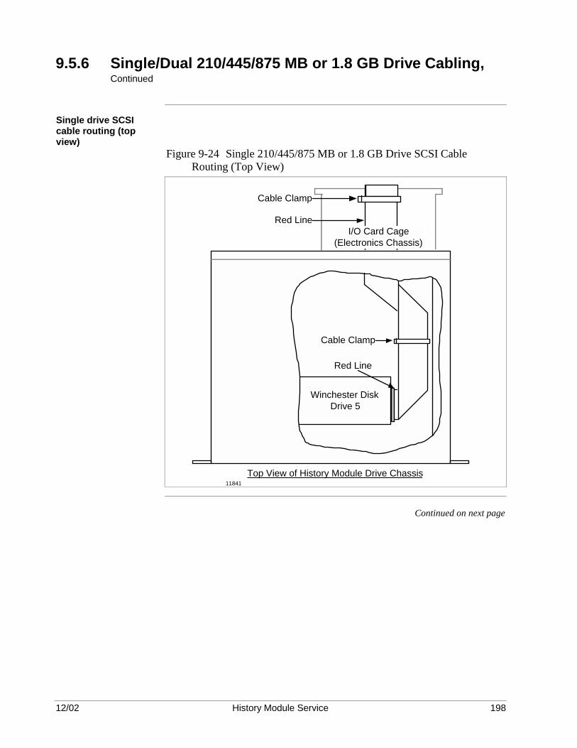
12/02 History Module Service 198
9.5.6 Single/Dual 210/445/875 MB or 1.8 GB Drive Cabling, Continued
Single drive SCSI cable routing (top view)
Figure 9-24 Single 210/445/875 MB or 1.8 GB Drive SCSI Cable Routing (Top View)
Red Line
Winchester Disk Drive 5
Top View of History Module Drive Chassis
Cable Clamp
I/O Card Cage (Electronics Chassis)
Cable Clamp
Red Line
11841
Continued on next page

12/02 History Module Service 199
9.5.6 Single/Dual 210/445/875 MB or 1.8 GB Drive Cabling, Continued
Single drive cable routing (side view)
Figure 9-25 Single 210/445/875 MB or 1.8 GB Drive SCSI Bus Cable Routing (Side View)
16768
Slide Tray Assembly
Winchester Drive Module
Drive 5SCSI Bus
Ribbon Cable
Electronics Module
SIDE VIEW
SPC I/O Connector
Continued on next page

12/02 History Module Service 200
9.5.6 Single/Dual 210/445/875 MB or 1.8 GB Drive Cabling, Continued
Dual drive cabling Figure 9-26 illustrates a side view of the SCSI bus cable routing for a nonredundant dual drive configuration. Note the cabling is similar to single drive cabling, but the cable continues on to the upper Winchester Drive Module (module #2) that contains the second drive. The cable is folded and clamped beside the drives on the tray assemblies in the same manner as illustrated in Figure 9-24. The upper Winchester Drive Module contains Drive 5, while the lower Winchester Drive Module contains Drive 3. The drive in the upper module has termination resistor modules installed on it to terminate the drive end of the SCSI bus cable.
Dual Winchester Drive Modules
Figure 9-26 Dual 210/445/875 MB or 1.8 GB Drive SCSI Cable Routing (Side View) – Dual Modules
16769
Slide Tray Assembly
Slide Tray Assembly
Winchester Drive Module #2
Winchester Drive Module #1
Electronics Module
Drive 5
Drive 3
SIDE VIEW
SCSI Bus Ribbon Cable
SPC I/O Connector
Continued on next page
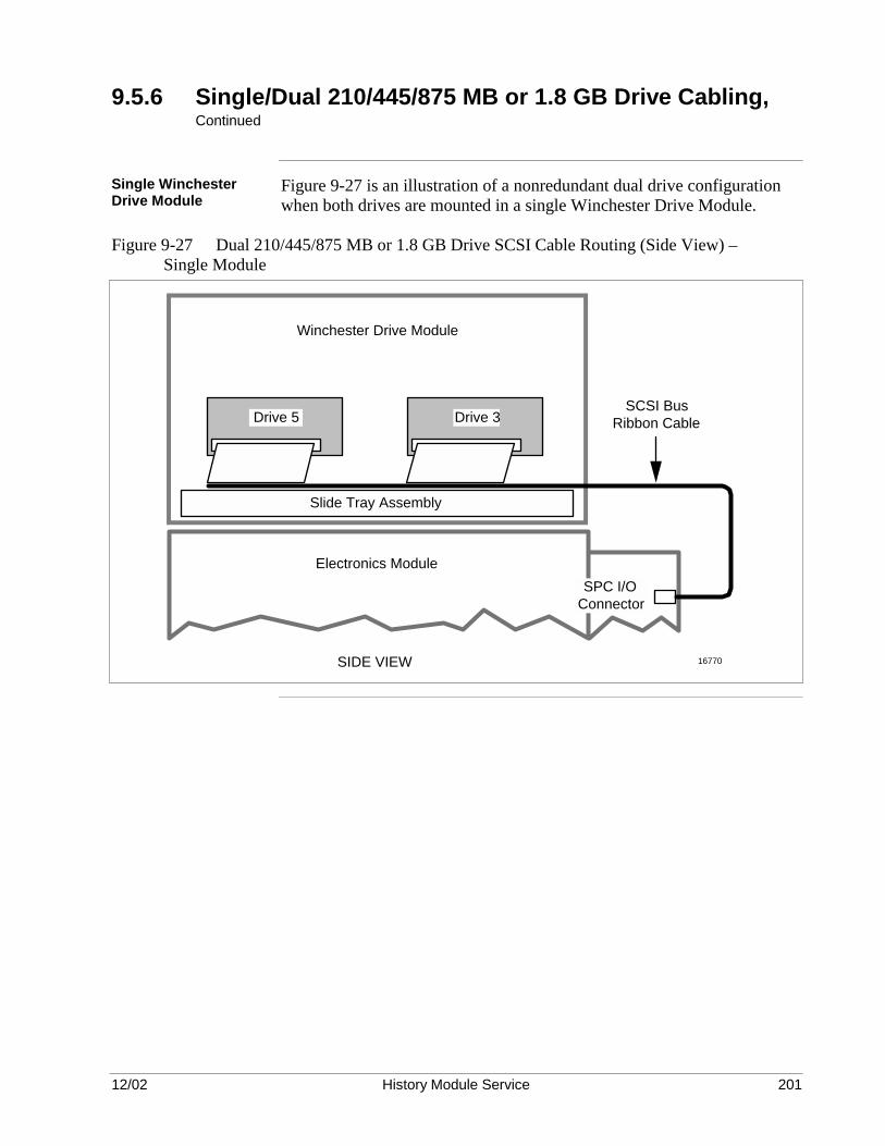
12/02 History Module Service 201
9.5.6 Single/Dual 210/445/875 MB or 1.8 GB Drive Cabling, Continued
Single Winchester Drive Module
Figure 9-27 is an illustration of a nonredundant dual drive configuration when both drives are mounted in a single Winchester Drive Module.
Figure 9-27 Dual 210/445/875 MB or 1.8 GB Drive SCSI Cable Routing (Side View) – Single Module
16770
Slide Tray Assembly
Winchester Drive Module
Drive 5SCSI Bus
Ribbon Cable
Electronics Module
SIDE VIEW
SPC I/O Connector
Drive 3

12/02 History Module Service 202
9.6 Redundant WREN III Drive Installation
Overview Use the supplemental information in this subsection when installing
WREN III drives and associated components in History Modules configured for redundant drives. The History Module contains redundant single or dual pairs of WREN III drives. The drives and associated components are configured by software to accept identical write data. If one of the drives fails, its unimpaired partner can assume operational responsibility until the failed drive can be repaired or replaced.
Drive configurations The redundant drive configurations that are illustrated in Figure 9-28 have
a few physical characteristics that are different from the “conventional” nonredundant configurations. The differences are presented in the following subsections. Figure 9-28 Redundant Drive Positioning and Address Assignments
16776Redundant Single Drives Redundant Dual Drives
Drive 5 Address = 5
Drive 4 Address = 4
Drive 3 Address = 3
Drive 4 Address = 4
Drive 2 Address = 2
Drive 2 Address = 5

12/02 History Module Service 203
9.6.1 Single Drive Installation
Overview The redundant single drive configuration is very similar to the dual drive
configuration. The differences are in address pinning, SCSI bus termination, and cabling.
9.6.1.1 Single WREN III Drive Pinning
Single drive pinning In the redundant single drive configuration, each drive is housed in a
separate Winchester Drive Module. The terminator resistor module must be removed from both drives. As illustrated in Figures 9-29 and 9-30, Drive 5 is mounted in the front position on the tray assembly in the upper module (module #2) and has a SCSI bus address of 5. Address 5 is selected by placing Drive Select Plugs in the “2” and “0” positions. In binary arithmetic, 22 + 20 = 4 + 1 = 5 decimal. Drive 4 is mounted in the front position on the tray assembly in the lower module (module #1) and has a SCSI bus address of 4. Address 4 is selected by placing a Drive Select Plug in the “2” position. In binary arithmetic, 22 = 4 decimal. Be sure that the terminator resistor module is removed from both drives. Bus termination is provided at the end of the SCSI bus cable by a bus terminator card for redundant single drives.
Continued on next page

12/02 History Module Service 204
9.6.1.1 Single WREN III Drive Pinning, Continued
Redundant single WREN III drive configuration
Figure 9-29 Redundant Single WREN III Drive Configuration
16771
Rear View Single Drive (Redundant Configuration Is Two Physical Drives)
Remove Terminators from both Drives
Drive ADrive 4
2 1 0 P TP Address 4
Drive ADrive 5
2 1 0 P TP Address 5
Set Jumpers as Shown for Correct System Address

12/02 History Module Service 205
9.6.1.2 Single WREN III Drive Cabling
Redundant single drive SCSI bus cable routing
Figure 9-30 illustrates a side view of the cable routing for a redundant single WREN III drive configuration. The single SCSI bus ribbon cable from the SPC I/O circuit board in the I/O cage in the rear of the electronics module passes through a slotted hole in the back of the lower Winchester Drive Module and routes over the slide tray assembly to Drive 4. The cable then exits the lower Winchester Drive Module and enters the upper module where it connects to Drive 5. It then connects to a bus terminator card mounted at the top of the upper Winchester Drive Module chassis.
Figure 9-30 Redundant Single WREN III Drive SCSI Bus Cable Routing (Side View)
16772
Slide Tray Assembly
Slide Tray Assembly
Winchester Drive Module #2
Winchester Drive Module #1
WREN III Drive 5
WREN III Drive 4
Bus Terminator Assembly
SCSI Bus Ribbon Cable
Electronics Module
SIDE VIEW
SPC I/O Connector
Continued on next page

12/02 History Module Service 206
9.6.1.2 Single WREN III Drive Cabling, Continued
Terminator/Card Guide assembly
The bus terminator card is illustrated in Figure 9-31.
Figure 9-31 Terminator/Card Guide Assembly
51195180 Card Guide
ASSY NO. 51195178 - 100 REV
C1 C2
RN2 1RN3 1 RN1 1
J1
49 50
1 2
Chassis
SCSI Terminator Board
Card Guides
A!
!!
+
2103
Ribbon cable red stripe positioning
Front and top views of the modules are illustrated in Figures 9-32 and 9-33, respectively. The SCSI bus cable always connects to a WREN III drive with the red stripe on the right side of the drive as you face the connectors on the drive.
Avoid the fan blades Use special care to prevent the ribbon cables from interfering with the
rotating fan blades in the fan assembly. The cables can be dressed under the WREN III drives to avoid the fan blades. Note that the cable is folded under the drive so it can make a 90° turn up to the drive connector as illustrated in Figure 9-33.
Continued on next page

12/02 History Module Service 207
9.6.1.2 Single WREN III Drive Cabling, Continued
Redundant WREN III drive cable installation (front view)
Figure 9-32 Redundant Single WREN III Drive SCSI Bus Cable Installation (Front View)
51195178 Bus Terminator
Electronics Module (Shown for Reference)
51195180 Card Guide
Locate Approximately as Shown
Red Line
Front View (Front Cover and Slide Assembly Omitted for Clarity)
Red Stripe
2101
Continued on next page

12/02 History Module Service 208
9.6.1.2 Single WREN III Drive Cabling, Continued
Redundant WREN III drive cable installation (top view)
Figure 9-33 Redundant Single WREN III Drive SCSI Bus Cable Installation (Top View)
16773
Red Stripe
Locate Approximately as Shown
I/O Card Cage
Red Stripe
Winchester Drive 5
Top View 51195180 Card Guide
51195178 Bus Terminator
12/02 History Module Service 209
9.6.2 Dual Drive Installation
Overview The redundant dual drive configuration consists of pairs of WREN III
drives mounted on separate slide-out tray assemblies in separate Winchester Drive Modules. They are configured so that one tray assembly, which might contain a failed drive, can be removed while the system continues to function with the redundant pair of drives on the other tray assembly.
9.6.2.1 Dual WREN III Drive Pinning
Dual drive pinning Be sure that the terminator resistor module is removed from all drives.
As illustrated in Figures 9-34 and 9-35, Drive 5 is mounted at the front position in the upper module (module #2) and has a SCSI bus address of 5. Address 5 is selected by placing Drive Select Plugs in the “2” and “0” positions. In binary arithmetic, 22 + 20 = 4 + 1 = 5 decimal. Drive 5’s redundant partner, Drive 4, is mounted at the front position in the lower module (module #1) and has a SCSI bus address of 4. Address 4 is selected by placing a Drive Select Plug in the “2” position. In binary arithmetic, 22 = 4 decimal. In a similar manner, Drive 3 is mounted at the rear position in the upper module and has a SCSI bus address of 3. Address 3 is selected by placing Drive Select Plugs in the “1” and “0” positions. In binary arithmetic, 21 + 20 = 2 + 1 = 3 decimal. Drive 3’s redundant partner, Drive 2, is mounted at the rear position in the lower module and has a SCSI address of 2. Address 2 is selected by placing a Drive Select Plug in the “1” position. In binary arithmetic, 21 = 2 decimal. SCSI bus termination is provided at the drive end of the cable by a bus terminator card for the redundant dual WREN III drives.
Continued on next page

12/02 History Module Service 210
9.6.2.1 Dual WREN III Drive Pinning, Continued
Redundant dual WREN III drive configuration
Figure 9-34 Redundant Dual WREN III Drive Configuration
Remove Terminators from All 4 Drives
Drive ADrive 4
2 1 0 P TP Address 4
Drive ADrive 5
2 1 0 P TP Address 5
Drive ADrive 3
2 1 0 P TP Address 3
Drive ADrive 2
2 1 0 P TP Address 2
Set Jumpers as Shown for Correct System Addresses
Rear View Dual Drives (Redundant Configuration Is Four Physical Drives)
16774

12/02 History Module Service 211
9.6.2.2 Dual WREN III Drive Cabling
Dual drive cabling Figure 9-35 illustrates a side view of the cable routing for redundant dual
WREN III drives. The single SCSI bus ribbon cable from the SPC I/O circuit card in the I/O card cage at the rear of the electronics module passes through a slotted hole in the back of the lower Winchester Drive Module and routes over the slide-out tray assembly to Drive 4, then back to Drive 2. The cable exits the lower Winchester Drive Module and enters the upper Winchester Drive Module where it connects to Drive 5, then to Drive 3. Finally, it connects to a bus terminator card that is mounted at the top of the upper Winchester Drive Module chassis. The bus terminator card is illustrated in Figure 9-31.
Ribbon cable red stripe positioning
A top view of the Winchester Drive Modules is illustrated in Figure 9-36. The SCSI bus ribbon cable always connects to a WREN III drive with the red stripe on the right side of the drive as you face the connectors on the drive.
Avoid the fan blades Use special care to prevent the ribbon cable from interfering with the
rotating fan blades in the fan assembly. The cable can be dressed under the WREN III drives to avoid the fan blades. As illustrated in Figure 9-36, the cable is also folded under the drive so it can make a 90° turn up to the drive connector.
Continued on next page

12/02 History Module Service 212
9.6.2.2 Dual WREN III Drive Cabling, Continued
Redundant dual WREN III drive SCSI bus cable routing
Figure 9-35 Redundant Dual WREN III Drive SCSI Bus Cable Routing (Side View)
16775
Winchester Drive Module #2
Winchester Drive Module #1
WREN III Drive 5
WREN III Drive 4
Bus Terminator Assembly
WREN III Drive 3
WREN III Drive 2
SCSI Bus Ribbon Cable
Electronics Module
SIDE VIEW
SPC I/O Connector
Slide Tray Assembly
Slide Tray Assembly
Continued on next page

12/02 History Module Service 213
9.6.2.2 Dual WREN III Drive Cabling, Continued
Redundant dual WREN III drive SCSI bus cable installation
Figure 9-36 Redundant Dual WREN III Drive SCSI Cable Installation (Top View)
16759
Winchester Drive 5 or 4
Red Stripe
51195180 Card Guide
51195178 Bus Terminator
Top View
I/O Card Cage
Red Stripe
Locate Approximately as Shown
Winchester Drive 3 or 2
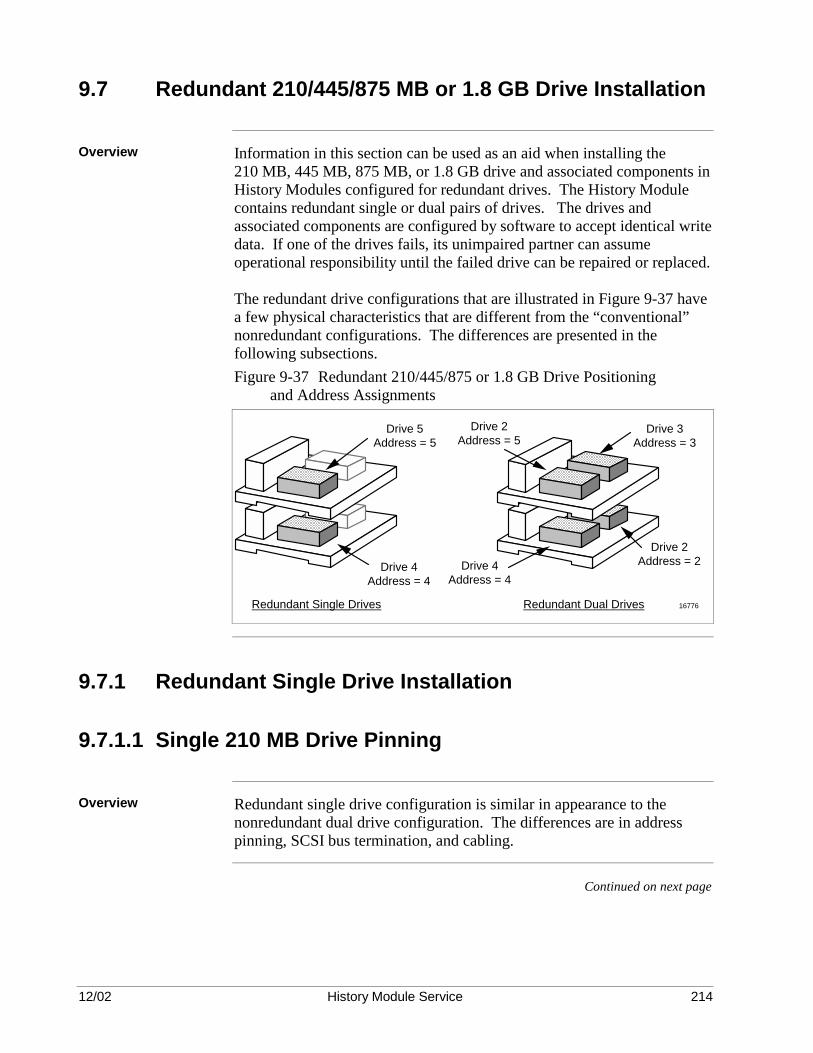
12/02 History Module Service 214
9.7 Redundant 210/445/875 MB or 1.8 GB Drive Installation
Overview Information in this section can be used as an aid when installing the
210 MB, 445 MB, 875 MB, or 1.8 GB drive and associated components in History Modules configured for redundant drives. The History Module contains redundant single or dual pairs of drives. The drives and associated components are configured by software to accept identical write data. If one of the drives fails, its unimpaired partner can assume operational responsibility until the failed drive can be repaired or replaced. The redundant drive configurations that are illustrated in Figure 9-37 have a few physical characteristics that are different from the “conventional” nonredundant configurations. The differences are presented in the following subsections. Figure 9-37 Redundant 210/445/875 or 1.8 GB Drive Positioning and Address Assignments
16776Redundant Single Drives Redundant Dual Drives
Drive 5 Address = 5
Drive 4 Address = 4
Drive 3 Address = 3
Drive 4 Address = 4
Drive 2 Address = 2
Drive 2 Address = 5
9.7.1 Redundant Single Drive Installation
9.7.1.1 Single 210 MB Drive Pinning
Overview Redundant single drive configuration is similar in appearance to the
nonredundant dual drive configuration. The differences are in address pinning, SCSI bus termination, and cabling.
Continued on next page
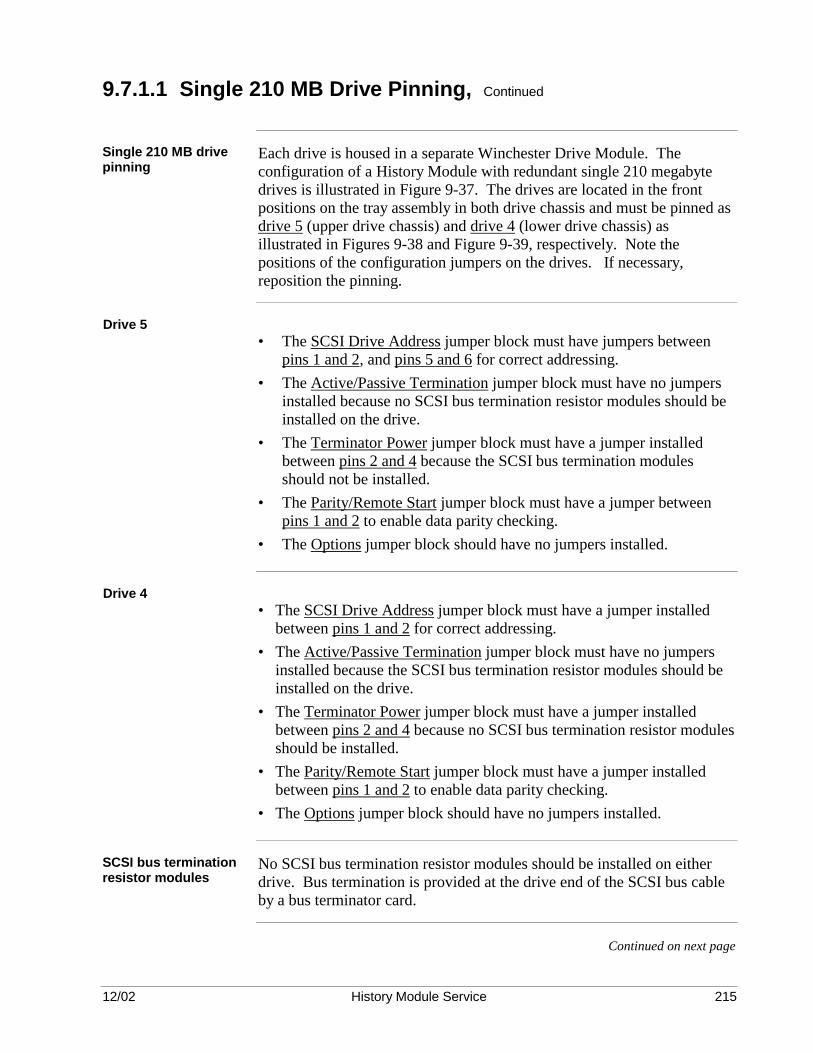
12/02 History Module Service 215
9.7.1.1 Single 210 MB Drive Pinning, Continued
Single 210 MB drive pinning
Each drive is housed in a separate Winchester Drive Module. The configuration of a History Module with redundant single 210 megabyte drives is illustrated in Figure 9-37. The drives are located in the front positions on the tray assembly in both drive chassis and must be pinned as drive 5 (upper drive chassis) and drive 4 (lower drive chassis) as illustrated in Figures 9-38 and Figure 9-39, respectively. Note the positions of the configuration jumpers on the drives. If necessary, reposition the pinning.
Drive 5
• The SCSI Drive Address jumper block must have jumpers between pins 1 and 2, and pins 5 and 6 for correct addressing.
• The Active/Passive Termination jumper block must have no jumpers installed because no SCSI bus termination resistor modules should be installed on the drive.
• The Terminator Power jumper block must have a jumper installed between pins 2 and 4 because the SCSI bus termination modules should not be installed.
• The Parity/Remote Start jumper block must have a jumper between pins 1 and 2 to enable data parity checking.
• The Options jumper block should have no jumpers installed.
Drive 4
• The SCSI Drive Address jumper block must have a jumper installed between pins 1 and 2 for correct addressing.
• The Active/Passive Termination jumper block must have no jumpers installed because the SCSI bus termination resistor modules should be installed on the drive.
• The Terminator Power jumper block must have a jumper installed between pins 2 and 4 because no SCSI bus termination resistor modules should be installed.
• The Parity/Remote Start jumper block must have a jumper installed between pins 1 and 2 to enable data parity checking.
• The Options jumper block should have no jumpers installed.
SCSI bus termination resistor modules
No SCSI bus termination resistor modules should be installed on either drive. Bus termination is provided at the drive end of the SCSI bus cable by a bus terminator card.
Continued on next page

12/02 History Module Service 216
9.7.1.1 Single 210 MB Drive Pinning, Continued
Nonterminated 210 MB Drive 5 jumper block selections
Figure 9-38 Nonterminated 210 MB Drive 5 Jumper Block Selections (Bottom View)
5 3 1 6 4 2
No Termination Resistor Modules
Parity/Remote Start Jumper Block
PWB
3 1 4 2
Options Jumper Block (None Selected for Drives 2-5)
PWB
Active/Passive Termination Jumper Block
PWB
Ground Signal
Terminator Power Jumper Block
PWB3 1 4 2
SCSI Drive Address Jumper Block PWB
Ground Signal
2 4 6 1 3 5
I/O Connector
9 7 10 8
5 3 6 4
1 2
13 11 14 12
Pin 1
DC Power Connector
PWB
+ 5 Vdc + 5 Volts Return + 12 Volts Return + 12 Vdc
1 2 3 4
Drive 5
Drive 5
Drive 5
Drive 5
(No jumpers)
51196220-100
11848
Continued on next page

12/02 History Module Service 217
9.7.1.1 Single 210 MB Drive Pinning, Continued
Nonterminated 210 MB Drive 4 jumper block selections
Figure 9-39 Nonterminated 210 MB Drive 4 Jumper Block Selections (Bottom View)
5 3 1 6 4 2
No Termination Resistor Modules
Parity/Remote Start Jumper Block
PWB
3 1 4 2
Options Jumper Block (None Selected for Drives 2-5)
PWB
Active/Passive Termination Jumper Block
PWB
Ground Signal
Terminator Power Jumper Block
PWB3 1 4 2
SCSI Drive Address Jumper Block PWB
Ground Signal
2 4 6 1 3 5
I/O Connector
9 7 10 8
5 3 6 4
1 2
13 11 14 12
Pin 1
DC Power Connector
PWB
+ 5 Vdc + 5 Volts Return + 12 Volts Return + 12 Vdc
1 2 3 4
Drive 4
Drive 4
Drive 4
Drive 4
(No jumpers)
51196220-100
11849
Continued on next page

12/02 History Module Service 218
9.7.1.2 Single 445 MB Drive Pinning
Overview Redundant single drive configuration is similar in appearance to the
nonredundant dual drive configuration. The differences are in address pinning, SCSI bus termination, and cabling.
Single 445 MB drive pinning
Each drive is housed in a separate Winchester Drive Module. The configuration of a History Module with redundant single 445 megabyte drives is illustrated in Figure 9-37. The drives are located in the front positions on the tray assembly in both drive chassis and must be pinned as drive 5 (upper drive chassis) and drive 4 (lower drive chassis) as illustrated in Figures 9-40 and Figure 9-41, respectively. Note the positions of the configuration jumpers on the drives. If necessary, reposition the pinning.
Drive 5
• The SCSI Drive Address jumper block must have jumpers installed in positions 1 and 3 for correct addressing.
• The Active/Passive Termination jumper block must have a jumper installed in position 5 to enable data parity checking. No SCSI bus termination resistor modules should be installed on the drive.
• The Options jumper block should have no jumpers installed on it.
Drive 4
• The SCSI Drive Address jumper block must have a jumper installed in position 3 for correct addressing.
• The Active/Passive Termination jumper block must have a jumper installed in position 5 to enable data parity checking. No SCSI bus termination resistor modules should be installed on the drive.
• The Options jumper block should have no jumpers installed on it.
SCSI bus termination resistor modules
No SCSI bus termination resistor modules should be installed on either drive. Bus termination is provided at the drive end of the SCSI bus cable by a bus terminator card.
Continued on next page

12/02 History Module Service 219
9.7.1.2 Single 445 MB Drive Pinning, Continued
Nonterminated 445 MB Drive 5 jumper block selections
Figure 9-40 Nonterminated 445 MB Drive 5 Jumper Block Selections (Bottom View)
Options Jumper Block (Not Used – No Jumpers)
1 2 3 4 5 6
Active/Passive Termination Jumper Block
1 2 3 4 5 6 7 8
SCSI Drive Address Jumper Block
3 2 1
DC Power Connector
+ + + +
5 Vdc 5 Volts Return 12 Volts Return 12 Vdc
1 2 3 4
PWB
PWB
PWB
PWB
Drive Bottom
Drive Bottom
12506-A
No SCSI BusTermination Resistor Modules
Continued on next page

12/02 History Module Service 220
9.7.1.2 Single 445 MB Drive Pinning, Continued
Nonterminated 445 MB Drive 4 jumper block selections
Figure 9-41 Nonterminated 445 MB Drive 4 Jumper Block Selections (Bottom View)
Options Jumper Block (Not Used – No Jumpers)
1 2 3 4 5 6
Active/Passive Termination Jumper Block
1 2 3 4 5 6 7 8
SCSI Drive Address Jumper Block
3 2 1
DC Power Connector
+ + + +
5 Vdc 5 Volts Return 12 Volts Return 12 Vdc
1 2 3 4
PWB
PWB
PWB
PWB
Drive Bottom
Drive Bottom
12504
No SCSI BusTermination Resistor Modules

12/02 History Module Service 221
9.7.1.3 Single 875 MB Drive Pinning
Overview Redundant single drive configuration is similar in appearance to the nonredundant dual drive configuration. The differences are in address pinning, SCSI bus termination, and cabling.
ATTENTION ATTENTION—Your History Module will contain one of two types of 875 megabyte drives. They are easily identified by their appearance and the Honeywell part number (51196680-100 or 51196680-200) on the drive. Be sure that you use the pinning procedure that matches the drive.
Single 875 MB drive configuration jumpers
Each drive is housed in a separate Winchester Drive Module. The configuration of a History Module with redundant single 875 megabyte drives is illustrated in Figure 9-37. The drives are located in the front positions on the tray assembly in both drive chassis and must be pinned as drive 5 (upper drive chassis) and drive 4 (lower drive chassis) as illustrated in Figures 9-42 through 9-45, respectively. Note the positions of the configuration jumpers on the drives. If necessary, reposition the jumpers.
875 MB Drive 5 (51196680-100)
• The SCSI Address (J5) jumper block must have jumpers installed in positions 1 and 3 for correct addressing.
• The Option Select (J2) jumper block must have a jumper installed in position 5 to enable data parity checking. The internal SCSI bus terminators on the drive must not be enabled.
• The SCSI Address/Remote (J6) jumper block must not have any jumpers installed on it.
875 MB Drive 4 (51196680-100)
• The SCSI Address (J5) jumper block must have a jumper installed in position 3 for correct addressing.
• The Option Select (J2) jumper block must have a jumper installed in position 5 to enable data parity checking. The internal SCSI bus terminators on the drive must not be enabled.
• The SCSI Address/Remote (J6) jumper block must not have any jumpers installed on it.
SCSI bus termination The internal SCSI bus terminators on either drive must not be enabled.
Bus termination is provided at the drive end of the SCSI bus cable by a bus terminator card.
Continued on next page
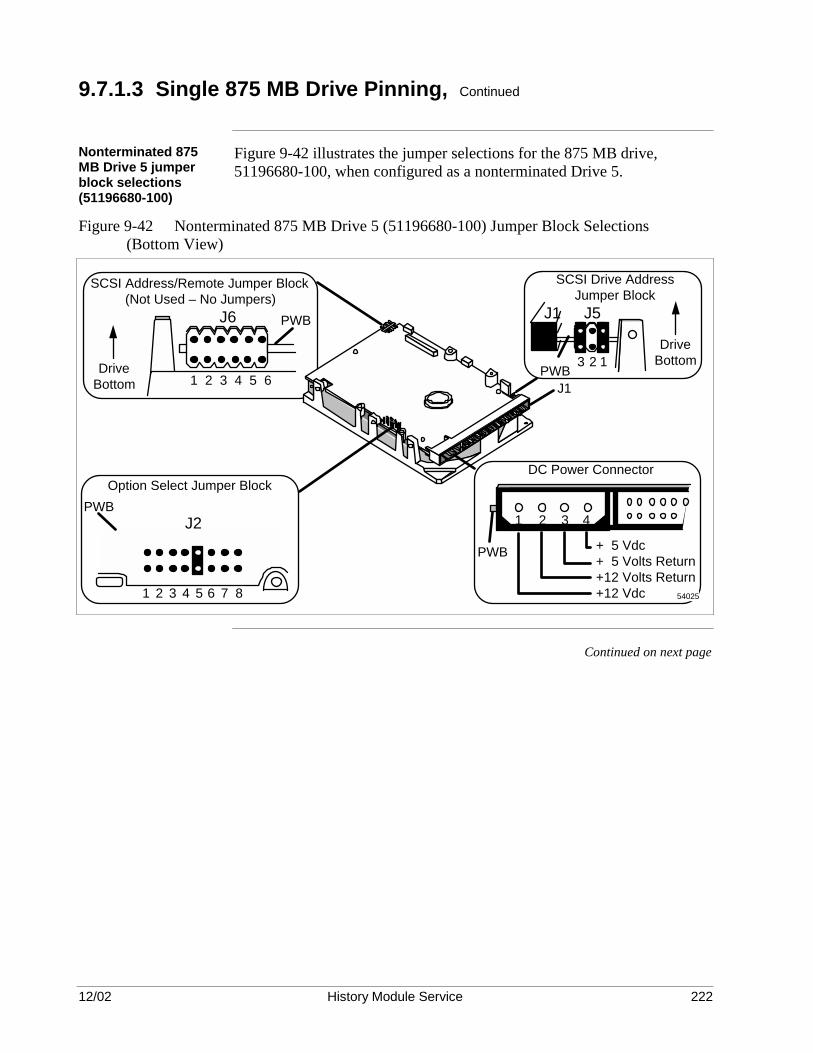
12/02 History Module Service 222
9.7.1.3 Single 875 MB Drive Pinning, Continued
Nonterminated 875 MB Drive 5 jumper block selections (51196680-100)
Figure 9-42 illustrates the jumper selections for the 875 MB drive, 51196680-100, when configured as a nonterminated Drive 5.
Figure 9-42 Nonterminated 875 MB Drive 5 (51196680-100) Jumper Block Selections (Bottom View)
Option Select Jumper BlockPWB
SCSI Address/Remote Jumper Block (Not Used – No Jumpers)
1 2 3 4 5 6Drive
Bottom
J6
J2
DC Power Connector
+ + + +
5 Vdc 5 Volts Return 12 Volts Return 12 Vdc
1 2 3 4
PWB
PWB
SCSI Drive Address Jumper Block
PWB
Drive Bottom3 2 1
J1
54025
J5J1
87654321
Continued on next page

12/02 History Module Service 223
9.7.1.3 Single 875 MB Drive Installation, Continued
Nonterminated 875 MB Drive 4 jumper block selections (51196680-100)
Figure 9-43 illustrates the jumper selections for the 875 MB drive, 51196680-100, when configured as a nonterminated Drive 4.
Figure 9-43 Nonterminated 875 MB Drive 4 (51196680-100) Jumper Block Selections (Bottom View)
Option Select Jumper BlockPWB
SCSI Address/Remote Jumper Block (Not Used – No Jumpers)
1 2 3 4 5 6Drive
Bottom
J6
J2
DC Power Connector
+ + + +
5 Vdc 5 Volts Return 12 Volts Return 12 Vdc
1 2 3 4
PWB
PWB
SCSI Drive Address Jumper Block
PWB
Drive Bottom3 2 1
J1
54026
J5J1
87654321
Continued on next page
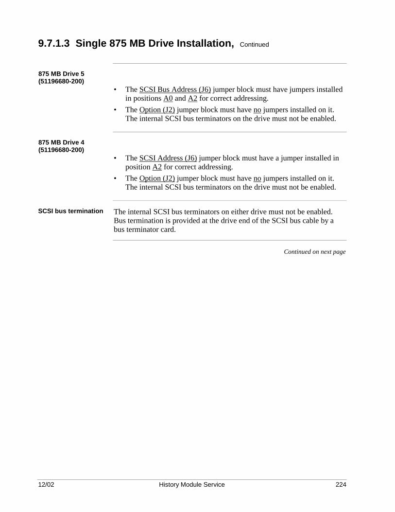
12/02 History Module Service 224
9.7.1.3 Single 875 MB Drive Installation, Continued
875 MB Drive 5 (51196680-200)
• The SCSI Bus Address (J6) jumper block must have jumpers installed in positions A0 and A2 for correct addressing.
• The Option (J2) jumper block must have no jumpers installed on it. The internal SCSI bus terminators on the drive must not be enabled.
875 MB Drive 4 (51196680-200)
• The SCSI Address (J6) jumper block must have a jumper installed in position A2 for correct addressing.
• The Option (J2) jumper block must have no jumpers installed on it. The internal SCSI bus terminators on the drive must not be enabled.
SCSI bus termination The internal SCSI bus terminators on either drive must not be enabled.
Bus termination is provided at the drive end of the SCSI bus cable by a bus terminator card.
Continued on next page

12/02 History Module Service 225
9.7.1.3 Single 875 MB Drive Pinning, Continued
Nonterminated 875 MB Drive 5 jumper block selections (51196680-200)
Figure 9-44 illustrates the jumper selections for the 875 MB drive, 51196680-200, when configured as a nonterminated Drive 5.
Figure 9-44 Nonterminated 875 MB Drive 5 (51196680-200) Jumper Block Selections (Bottom View)
SCSI BusTerminationResistor Modules
(Pin 1)
16727-B
SCSI Bus Address Jumper Block(Drive 5)
DriveBottom
J6PWB
TE DS ME WP PD SS TP TPPWB
J2
Option Jumper Block(Drive 5 Nonterminated)
A2A1A0
Continued on next page

12/02 History Module Service 226
9.7.1.3 Single 875 MB Drive Installation, Continued
Nonterminated 875 MB Drive 4 jumper block selections (51196680-200)
Figure 9-45 illustrates the jumper selections for the 875 MB drive, 51196680-200, when configured as a nonterminated Drive 4.
Figure 9-45 Nonterminated 875 MB Drive 4 (51196680-200) Jumper Block Selections (Bottom View)
SCSI BusTerminationResistor Modules
(Pin 1)
16729-B
SCSI Bus Address Jumper Block(Drive 4)
DriveBottom
J6
PWB
PWB
TE DS ME WP PD SS TP TP
J2
Option Jumper Block(Drive 4 Nonterminated)
A2A1A0

12/02 History Module Service 227
9.7.1.4 Single 1.8 GB Drive Pinning
Overview Redundant single drive configuration is similar in appearance to the
nonredundant dual drive configuration. The differences are in address pinning, SCSI bus termination, and cabling.
Single 1.8 GB drive pinning
Each drive is housed in a separate Winchester Drive Module. The configuration of a History Module with redundant single 1.8 gigabyte drives is illustrated in Figure 9-31. The drives are located in the front positions on the tray assembly in both drive chassis and must be pinned as drive 5 (upper drive chassis) and drive 4 (lower drive chassis) as illustrated in Figures 9-46 and Figure 9-47, respectively. Note the positions of the configuration jumpers on the drives. If necessary, reposition the jumpers.
Drive 5
• The SCSI Address (J6) jumper block must have jumpers installed in positions A0 and A2 for correct addressing.
• The Option Select (J2) jumper block must not have any jumpers installed on it.
Drive 4
• The SCSI Address (J6) jumper block must have a jumper installed in position A2 for correct addressing.
• The Option Select (J2) jumper block must not have any jumpers installed on it.
SCSI bus termination The internal SCSI bus terminators on either drive must not be enabled.
Bus termination is provided at the drive end of the SCSI bus cable by a bus terminator card.
Continued on next page

12/02 History Module Service 228
9.7.1.4 Single 1.8 GB Drive Pinning, Continued
Nonterminated 1.8 GB Drive 5 jumper block selections
Figure 9-46 Nonterminated 1.8 GB Drive 5 Jumper Block Selections (Bottom View)
SCSI BusTerminationResistor Modules
(Pin 1)
16727-B
SCSI Bus Address Jumper Block(Drive 5)
DriveBottom
J6PWB
TE DS ME WP PD SS TP TPPWB
J2
Option Jumper Block(Drive 5 Nonterminated)
A2A1A0
Continued on next page
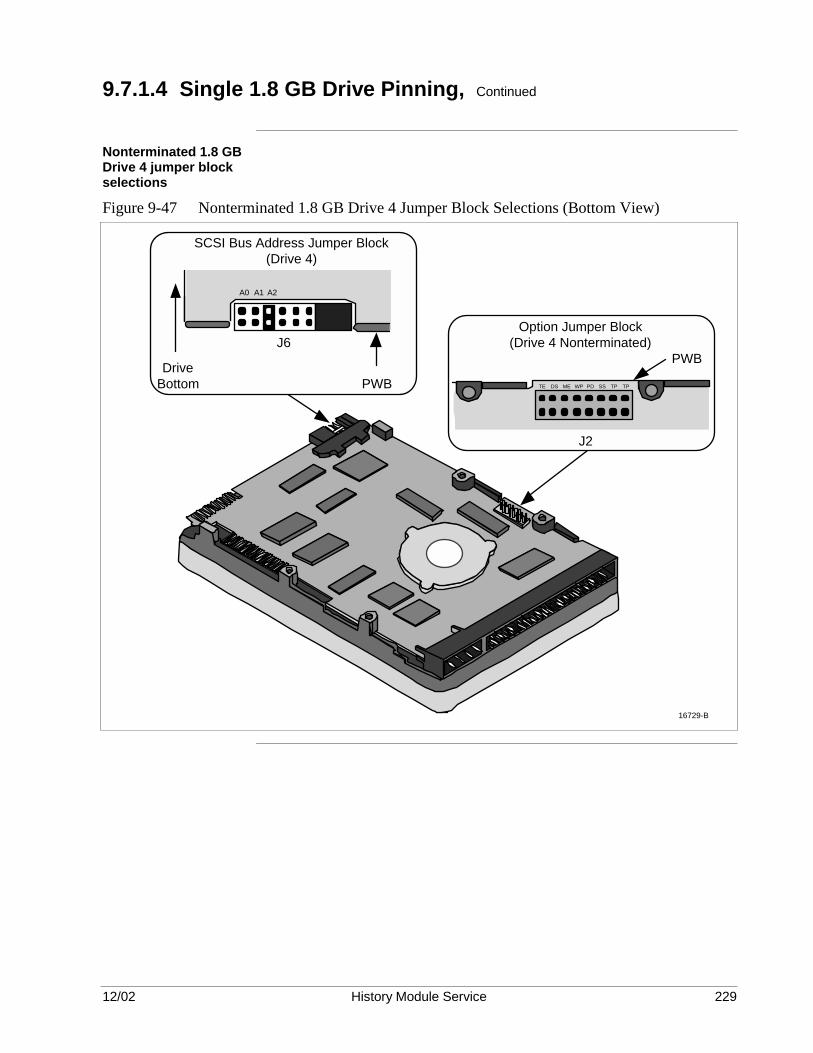
12/02 History Module Service 229
9.7.1.4 Single 1.8 GB Drive Pinning, Continued
Nonterminated 1.8 GB Drive 4 jumper block selections
Figure 9-47 Nonterminated 1.8 GB Drive 4 Jumper Block Selections (Bottom View)
SCSI BusTerminationResistor Modules
(Pin 1)
16729-B
SCSI Bus Address Jumper Block(Drive 4)
DriveBottom
J6
PWB
PWB
TE DS ME WP PD SS TP TP
J2
Option Jumper Block(Drive 4 Nonterminated)
A2A1A0

12/02 History Module Service 230
9.7.1.5 Single 210/445/875 MB or 1.8 GB Drive Cabling
Single drive cabling Figure 9-48 illustrates a side view of the cable routing for a redundant
single 210 MB, 445 MB, 875 MB, or 1.8 GB drive configuration. The single SCSI bus ribbon cable from the SPC I/O circuit board, that is located in the card cage at the rear of the electronics module, passes through a slotted hole in the back of the lower Winchester Drive Module and routes over the slide-out tray assembly to Drive 4. The cable then exits the lower Winchester Drive Module and enters the upper Winchester Drive Module where it connects to Drive 5. It then connects to a bus terminator resistor card mounted at the top of the upper Winchester Drive Module chassis. The bus terminator resistor card is illustrated in Figure 9-31.
Ribbon cable red stripe positioning
A top view of the modules is illustrated in Figure 9-49. The SCSI bus ribbon cable always connects to a drive with the red stripe on the right side of the drive as you face the connectors on the drive.
Avoid the fan blades Use special care to prevent the ribbon cables from interfering with the
rotating fan blades in the fan assembly. The cables must be held in place on the tray assemblies by cable clamps to avoid the fan blades. The cable is folded so it can make a 90° turn up to the drive connector as illustrated in Figure 9-49.
Continued on next page

12/02 History Module Service 231
9.7.1.5 Single 210/445/875 MB or 1.8 GB Drive Cabling, Continued
Redundant single drive SCSI bus cable routing
Figure 9-48 Redundant Single 210/445/875 MB or 1.8 GB Drive SCSI Bus Cable Routing (Side View)
16777
Slide Tray Assembly
Slide Tray Assembly
Winchester Drive Module #2
Winchester Drive Module #1
Electronics Module
Drive 5
SIDE VIEW
SCSI Bus Ribbon Cable
SPC I/O Connector
Drive 4
Continued on next page

12/02 History Module Service 232
9.7.1.4 Single 210/445/875 MB or 1.8 GB Drive Cabling, Continued
Redundant single drive SCSI bus cable installation
Figure 9-49 Redundant Single 210/445/875 MB or 1.8 GB Drive SCSI Bus Cable Installation (Top View)
Top View of Lower Drive Chassis
Red Line
Cable Clamps
I/O Card Cage (Electronic Chassis)
Top View of Upper Drive Chassis
Red Line
Cable Clamps
Bus Terminator
Winchester Disk Drive 5
Winchester Disk Drive 4
Cable ClampRed Line
11851
12/02 History Module Service 233
Section 10 – WDA Type History Module Assembly
10.1 Overview
Section contents The topics covered in this section are:
Topic See Page 10.1 Overview 257 10.2 History Module Assembly 259 10.2.1 General Assembly 259 10.2.2 Fan Assembly Replacement 260 10.2.3 Power Supply Replacement 260 10.2.4 Circuit Board Replacement 261 10.2.5 Cabling Replacement 270 10.2.6 Winchester Disk Assembly Replacement 271 10.3 Winchester Disk Assembly Reassembly 272 10.4 Winchester Drive Tray Assembly 273 10.4.1 General Information 273 10.4.2 Winchester Disk Drive Replacement 275
Purpose This section describes the assembly of the WDA History Module with
major components that includes the circuit boards, Winchester Disk Assembly, Winchester disk drive(s), power supply, fan assembly, and the module cabling.
Reference Refer to the Five/Ten-Slot Module Service manual for assembly
procedures where applicable. In particular, the installation of the K2LCN or K4LCN circuit board and its associated I/O circuit board, the LCN I/O (CLCN A/B), is detailed in the Five/Ten-Slot Module Service manual. All the other circuit boards used in the WDA History Module, other than the Smart Peripheral Controller (SPC) circuit board, are unique to the WDA History Module.
Continued on next page

12/02 History Module Service 234
10.1 Overview, Continued
History Module description
The Winchester Disk Assembly that occupies the upper two card slot locations in the module chassis can contain two Winchester Drive Trays. The trays are physically and electrically identical except for the number of drives the tray contains. Depending on the History Module configuration, one or two Winchester disk drives are mounted on the tray. See Section 2 for a description of the allowable drive configurations. A nonredundant History Module will have single or dual drives mounted on the right-hand tray. The left-hand tray will be absent. A redundant History Module will have single or dual drives mounted on both the right-hand and left-hand trays. The number of drives and their orientation must be the same on each tray. A tray can be installed in the Winchester Disk Assembly while power is applied to the History Module (the power supply’s ON/OFF switch is in the ON position). However, the tray’s ON/OFF switch must be in the OFF position when installing the tray.
CAUTION CAUTION—Always follow proper ESD (Electrostatic Discharge) procedures when handling circuit boards and other electronic components.

12/02 History Module Service 235
10.2 History Module Assembly
10.2.1 General Assembly
Purpose This subsection contains instructions for the assembly of the WDA History Module. Use those subsections necessary to reassemble the module with parts you removed by following instructions in Section 4. When specific configuration or cabling instructions for a given part or assembly are required, notes or special instructions in the text will assist you, or reference you, to the subsection where those instructions can be found. The item numbers used in this section are keyed to ballooned numbers in Figure 10-1. These item numbers are also used in Section 6, WDA Type History Module Disassembly. Figures 3-1 and 3-2 is other views of a typical History Module assembly. The CE Compliant version is slightly different in appearance.
Figure 10-1 WDA History Module Exploded View
6761
1
23
10
7
5
6
49
8
12
11
CAUTION CAUTION—When assembling the History Module, power must be removed from the module, either by disconnecting the module’s power cord or by placing the power supply’s ON/OFF switch in the OFF position, whichever is applicable.
The exception is the installation of a Winchester Drive Tray. The tray can be installed while power is applied to the module, but the tray’s ON/OFF switch must be in the OFF position when installing the tray. However, the tray’s ON/OFF switch must be placed in the ON position immediately after installing the tray.

12/02 History Module Service 236
10.2.2 Fan Assembly Replacement
Assembly procedure Slide the fan assembly (3) into the chassis, being careful that the connector
at the rear of the assembly mates properly. Secure the fan assembly with the two fasteners.
10.2.3 Power Supply Replacement
Assembly procedure Be sure the power supply’s ON/OFF switch is in the OFF position. Slide
the power supply (2) into the module until it begins to mate with its backpanel connectors. Then press on the extractor levers located on each side of the assembly until the power supply is fully mated with the backpanel connectors.

12/02 History Module Service 237
10.2.4 Circuit Board Replacement
CAUTION CAUTION—All circuit boards used in the History Module contain electrostatically sensitive devices. Use a personnel grounding strap and grounded work surfaces/equipment. Store and transport the parts only in electrostatically safe containers.
Correct circuit board pinning
When replacing an SPC circuit board that was removed from the History Module, be sure the address pinning (TS1) on the replacement board matches the removed board. Do not attempt to duplicate the revision pinning (TS2).
Smart Peripheral Controller (SPC) circuit board
Verify the selection of the pinning jumpers on the TS1 module on the Smart Peripheral Controller (SPC) circuit board (13) as illustrated in Figure 10-2. The revision pinning on the TS2 module has been determined in the factory and must not be changed in the field. Inspect the Smart Peripheral Controller circuit board for the proper firmware revision. It must be revision “G,” or a later revision. The two firmware EPROMs are located approximately at coordinates 18F and 18G as illustrated in Figure 10-2. If replacement is required, note the orientation and location of the EPROMs 0928-101 and 0928-102 before removal. Be sure to wear an ESD wriststrap that is properly grounded. Remove the EPROMs and replace them. Change the firmware revision on the circuit board. Slide the SPC circuit board (13), as illustrated in Figure 10-1, into slot 3 of the module chassis until it is fully mated with the backpanel connectors.
Continued on next page

12/02 History Module Service 238
10.2.4 Circuit Board Replacement, Continued
SPC circuit board SCSI bus address pinning
Figure 10-2 SCSI Bus Address Pinning on SPC Circuit Board
TS2
TS1
Board Revision Socket DO NOT CHANGE
Configure TS1 as follows: PINS DESCRIPTION 9-8 Always Shorted 10-7 Always Shorted 11-6 Always Shorted 12-5 Always Shorted 13-4 Short = WREN III or WDA History Module * 14-3 Open ** 15-2 Open ** 16-1 Open ** * = Setting for this application ** = SCSI Address 7 for this application
SPCASSY No.51401052-100
ADDR REV
910111213141516
87654321
0928
-101
REV
. G09
28-1
02R
EV. G
0928
-102
0928
-101
12554
SPC II (SPC2) I/O circuit board
The SPC II (SPC2) I/O circuit board (8) is associated with the SPC circuit board and is installed in slot 2 of the rear card cage as illustrated in Figure 10-1. Slide the SPCII I/O circuit board into the slot until fully mated with the backpanel connectors. There are no pinning requirements on the board.
Continued on next page

12/02 History Module Service 239
10.2.4 Circuit Board Replacement, Continued
LCN address configuration
The LCN node address can be selected on either the K2LCN (K4LCN) circuit board or the LCN I/O (CLCN A/B) board. Configuring the LCN node address on the K2LCN (K4LCN) circuit board is preferred for consistency, but selecting the address on either circuit board is acceptable. However, all the jumpers on the circuit board that is not being used for address selection must be removed, or if the board uses configuration switches as a substitute for the jumpers, the switches must be placed in their zero (0) position.
K2LCN circuit board LCN node address selection
The early production and current production K2LCN circuit boards (11), as illustrated in Figures 10-3 and 10-4, have an LCN node address pinning module at coordinate 9C and 7A, respectively. Pin the K2LCN board for the appropriate LCN node address. All jumpers on the LCN I/O circuit board must be removed if the LCN address is selected on the K2LCN circuit board. If a CLCN A/B is present, its configuration switches must be in their zero (0) position. The early production and current production K4LCN circuit boards (11), as illustrated in Figures 10-5 and 10-6, have an LCN node address pinning module, TS2, at locations 21E and 7A, respectively. Pin the K4LCN board for the appropriate LCN node address. All jumpers on the LCN I/O circuit board must be removed if the LCN address is selected on the K4LCN circuit board. If a CLCN A/B board is present, its configuration switches must be in their zero (0) position. As illustrated in Figure 10-1, slide the K2LCN or K4LCN circuit board (11) into slot 1 until it is fully mated with the backpanel connectors after selecting the appropriate LCN node address.
Continued on next page

12/02 History Module Service 240
10.2.4 Circuit Board Replacement, Continued
K2LCN (51401551-x00) LCN address selection
Figure 10-3 illustrates LCN node address selection on the K2LCN board, assembly 51401551-x00. The pinning block, TS2, is located at coordinate 9C on the board. The absence of a jumper is a binary “1.” Parity must be an odd number.
Figure 10-3 K2LCN Board (51401551-x00) LCN Node Address Selection
9D
9F
9H
9C
TS2
Jumper Removed = "1"
P
64
32
16
8
4
2
1
Binary Weight Parity
9467
65
43
21
0NOTE: This text is not on the board.
K2LCN
Continued on next page

12/02 History Module Service 241
10.2.4 Circuit Board Replacement, Continued
K2LCN (51402615-x00) LCN address selection
Figure 10-4 illustrates LCN node address selection on the K2LCN board, assembly 51402615-x00. The pinning block, TS1, is located at coordinate 7A on the board. The absence of a jumper is a binary “1.” Parity must be an odd number.
Figure 10-4 K2LCN Board (51402615-x00) LCN Node Address Selection
4C
8H3H
7A
TS1
Jumper Removed = "1" The overall number of jumpers removed, including the parity jumper, must be an odd number. This example indicates node address 03.
7739
NOTE: This text is not on the board.
K2LCN
P
64
32
16
8
4
2
1
Binary Weight Parity
65
43
21
0
Continued on next page
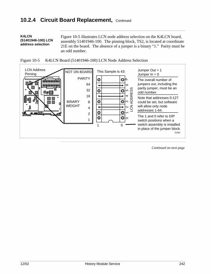
12/02 History Module Service 242
10.2.4 Circuit Board Replacement, Continued
K4LCN (51401946-100) LCN address selection
Figure 10-5 illustrates LCN node address selection on the K4LCN board, assembly 51401946-100. The pinning block, TS2, is located at coordinate 21E on the board. The absence of a jumper is a binary “1.” Parity must be an odd number.
Figure 10-5 K4LCN Board (51401946-100) LCN Node Address Selection
LCN Address Pinning
Jumper Out = 1 Jumper In = 0
NOT ON BOARD
PARITY 64
32
16
8 4
2
11 0
01
23
45
6P
LCN
AD
DR
ESS
The overall number of jumpers out, including the parity jumper, must be an odd number.
BINARY WEIGHT
The 1 and 0 refer to DIP switch positions when a switch assembly is installed in place of the jumper block.
Note that addresses 0-127 could be set, but software will allow only node addresses 1-64.
This Sample is 43:
51081
Continued on next page

12/02 History Module Service 243
10.2.4 Circuit Board Replacement, Continued
K4LCN (51402755-100) LCN address selection
Figure 10-6 illustrates LCN node address selection on the K4LCN board, assembly 51402755-100. The pinning block, TS1, is located at coordinate 7A on the board. The absence of a jumper is a binary “1.” Parity must be an odd number.
Figure 10-6 K4LCN Board (51402755-100) LCN Node Address Selection
4C
8H3H
7A
TS1
Jumper Removed = "1" The overall number of jumpers removed, including the parity jumper, must be an odd number. This example indicates node address 03.
773
NOTE: This text is not on the board.
K2LCN
P
64
32
16
8
4
2
1
Binary Weight Parity
65
43
21
0
Continued on next page

12/02 History Module Service 244
10.2.4 Circuit Board Replacement, Continued
LCN I/O board LCN node address selection
The LCN I/O and CLCN A/B circuit boards (7) are associated with the K2LCN and K4LCN circuit boards and are installed in slot 1 of the rear card cage as illustrated in Figure 10-1. The LCN I/O circuit board must be revision T or higher and must be configured for the appropriate LCN node address as illustrated in Figure 8-7. All jumpers on the K2LCN or K4LCN circuit board must be removed if the LCN address is selected on the LCN I/O circuit board. Slide the board into the slot until it is fully mated with the backpanel connectors after configuring the board for the appropriate LCN node address.
Figure 10-7 LCN I/O Board LCN Node Address Selection
Jumper Removed = "1" Overall number of jumpers omitted, including the parity jumper, must be an odd number. This example indicates node address 03.
The software will allow only node addresses 1-64 at this time.NOTE:
0
1
2
3
4
5
6
P
1
2
4
8
16
32
64
Binary Weight Parity
LCN
AD
DR
ESS
51107403-100
LCN I/O BOARD FROM REAR SLOT 2
2923
Continued on next page
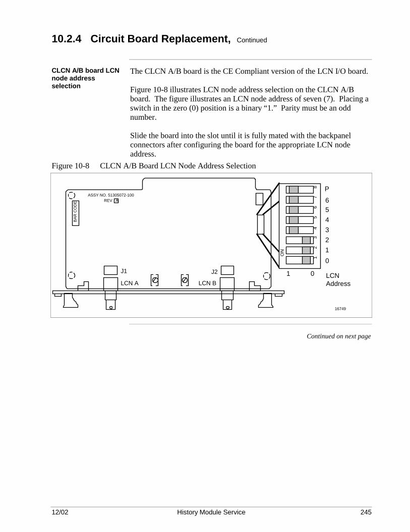
12/02 History Module Service 245
10.2.4 Circuit Board Replacement, Continued
CLCN A/B board LCN node address selection
The CLCN A/B board is the CE Compliant version of the LCN I/O board. Figure 10-8 illustrates LCN node address selection on the CLCN A/B board. The figure illustrates an LCN node address of seven (7). Placing a switch in the zero (0) position is a binary “1.” Parity must be an odd number. Slide the board into the slot until it is fully mated with the backpanel connectors after configuring the board for the appropriate LCN node address.
Figure 10-8 CLCN A/B Board LCN Node Address Selection
BAR
CO
DE
ASSY NO. 51305072-100 REV A
LCN A
J1
LCN B
J2 1 0
0123456P
LCN Address
ON
12
34
56
78
16749
Continued on next page

12/02 History Module Service 246
10.2.4 Circuit Board Replacement, Continued
WDI I/O circuit board The WDI I/O circuit board (9) is associated with the Winchester Drive
Interface (WDI) circuit board located in the Winchester Disk Assembly (4) and is installed in slot 5 of the rear card cage as illustrated in Figure 10-1. There are no pinning requirements on the circuit board. Slide the board into the slot until it is fully mated with the backpanel connectors.
10.2.5 Cabling Replacement
Overview The History Module requires the connection of two external cable sets to
service its two interfaces. The interfaces are described below.
Winchester drive interface
An interface between the SPCII (SPC2) I/O circuit board (8), located in slot 2 of the History Module’s rear card cage, and the WDI I/O circuit board (9), located in slot 5 of the rear card cage, is provided by two 50-pin ribbon cables (10). The interface is the SCSI bus interface between the SPC circuit board (12) and any Winchester disk drives mounted on the Winchester Drive Trays (5 and 6) in the Winchester Disk Assembly. The sets of ribbon cable connectors are keyed and friction-mate with connectors on the SPCII (SPC2) I/O and WDI I/O circuit boards as illustrated in Figure 10-1. Do not grasp the ribbon cable when making the connection. Grasp only the ribbon cable connectors.
Local Control Network interface
Two coaxial trunk cables, A and B, provide the interface to the Local Control Network (LCN). The trunk cables are color coded, with cable A coded yellow, and cable B coded green. The connections to the LCN (CLCN A/B) I/O circuit board (7), located in slot 1 of the module’s rear card cage, are made with tee connectors. Connect the LCN trunk cables, noting the identification labels and color codes on the cables. Match the cables to the proper connector on the LCN I/O circuit board. Do not cross-connect the cable connections.

12/02 History Module Service 247
10.2.6 Winchester Disk Assembly Replacement
WDA replacement As illustrated in Figure 10-1, the Winchester Disk Assembly (4) occupies
slots 4 and 5 in the History Module chassis. Figure 10-9 is an illustration of the assembly. The Winchester Disk Assembly connectors mate with the backpanel connectors in the slot 5 position, but is guided into position by the circuit board guide rails for the slot 4 position. Grasping the metal partition dividing the tray compartments, with the tray(s) disengaged or removed, is a convenient way of inserting the assembly into its backpanel connectors. The friction of the backpanel connectors tends to hold the assembly in place. However, two fasteners, located toward the front of each side of the assembly, secure it in place. The fan assembly must be removed to have access for the right-hand side fastener. Figure 10-9 Winchester Disk Assembly
6770

12/02 History Module Service 248
10.3 Winchester Disk Assembly Reassembly
Description As illustrated in the exploded view of the Winchester Disk Assembly, Figure 10-10, the assembly is composed of a chassis (1), a Winchester Drive Interface (WDI) circuit board (2), and one or two Winchester Drive Trays, right-hand (3) and left-hand (4), that reside in the chassis. The trays are physically interchangeable assemblies, but must be properly configured for their application in the History Module. Refer to subsection 10.4. Figure 10-10 Winchester Disk Assembly Exploded View
WDI Circuit Board
6771
1
2
3
4
Tray removal and replacement
Each tray (3 or 4) is held in place by an extractor lever and by the friction of the tray’s mating connectors. The tray is removed from the assembly by pulling outward on the tray’s extractor lever and sliding the tray out of the chassis.
WDI circuit board The Winchester Drive Interface (WDI ) circuit board (2) is installed with five phillips-head screws at the corners and forward center of the board that are accessible through holes at the top of the assembly chassis. A 1.27-mm (.050-inch) spacer (washer) must be used between the circuit board and the metal chassis at each screw location. It is very important that the spacers are used in mounting the board, because without the spacers the board will not properly mate with the backpanel connectors. Since it is very difficult to install the WDI circuit board using spacers, it is recommended that the circuit board not be replaced in the field. Instead, the Winchester Disk Assembly should be replaced if it is suspected that the circuit board has failed.
Tray installation A Winchester Drive Tray (3 or 4) is installed in the assembly by gently sliding it into its compartment until it begins to mate with the WDI board. Then firmly apply pressure to the front of the tray until the extractor lever assumes a relaxed position that is parallel to the tray’s front panel.

12/02 History Module Service 249
10.4 Winchester Drive Tray Assembly
10.4.1 General Information
Introduction The item numbers identified in parentheses ( ) in this subsection are
represented by the ballooned numbers in Figures 10-11 and 10-12, which are exploded views of the Winchester Drive Tray. Figure 10-11 Single-Drive Winchester Drive Tray Exploded View
6769
1
5
47
8 6
3
Figure 10-12 Dual-Drive Winchester Drive Tray Exploded View
6768
1
2
3
47
8 6
Continued on next page
12/02 History Module Service 250
10.4.1 General Information, Continued
Description A Winchester Drive Tray consists of the following components: • One or two Winchester disk drives (1 or 2). A single-drive tray
contains one drive and a dual-drive tray contains two drives. • A printed flex-circuit (3) interconnects the drive(s) with the tray
connector (4) that interfaces to the WDI circuit board in the Winchester Disk Assembly. The printed flex-circuit provides the SCSI bus interface to the drive(s).
• A connector hold-back bracket (5) that prevents damage to the printed flex-circuit when only the front drive is mounted on the tray. The connector hold-back bracket is installed to rigidly hold the unused connector in place. It is held in place by two Phillips-head screws using holes intended for mounting the rear drive. The connector attaches to the bracket with two screws.
• A power ON/OFF switch (6) to control power from the power supply to
the drive(s) and SCSI bus terminators on the WDI circuit board in the Winchester Disk Assembly. When power is removed from the tray, SCSI bus terminators are activated on the WDI circuit board in anticipation of the loss of the bus terminators installed on a Winchester disk drive in the tray that is about to be removed. Terminators are installed on the drive that is mounted at the front of tray.
• A tray power connector (7) that interfaces to the WDI circuit board in
the Winchester Disk Assembly and provides +5 Vdc, +12 Vdc, and ground return to the drive(s) from the power supply.
• An extractor lever (8) used to both lock the tray in place in the
Winchester Disk Assembly and assist in extracting the tray when it is in place.
Disk drive SCSI bus termination
When a Winchester Drive Tray has a single drive, the drive is mounted at the front of the tray. If the drive is a 210 megabyte or 445 megabyte drive, three SCSI bus termination modules must be installed on the drive. If the drive is a 875 megabyte or 1.8 gigabyte drive, the internal SCSI bus terminators on the drive must be enabled by jumper block pinning. A tray containing dual drives has drives mounted at both the front and rear of the tray. Only the front drive must terminate the SCSI bus. Refer to subsection 10.4.2 for the pinning and termination information for an individual drive.
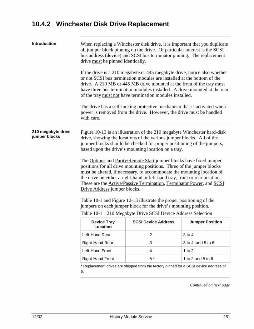
12/02 History Module Service 251
10.4.2 Winchester Disk Drive Replacement
Introduction When replacing a Winchester disk drive, it is important that you duplicate
all jumper block pinning on the drive. Of particular interest is the SCSI bus address (device) and SCSI bus terminator pinning. The replacement drive must be pinned identically. If the drive is a 210 megabyte or 445 megabyte drive, notice also whether or not SCSI bus termination modules are installed at the bottom of the drive. A 210 MB or 445 MB drive mounted at the front of the tray must have three bus termination modules installed. A drive mounted at the rear of the tray must not have termination modules installed. The drive has a self-locking protective mechanism that is activated when power is removed from the drive. However, the drive must be handled with care.
210 megabyte drive jumper blocks
Figure 10-13 is an illustration of the 210 megabyte Winchester hard-disk drive, showing the locations of the various jumper blocks. All of the jumper blocks should be checked for proper positioning of the jumpers, based upon the drive’s mounting location on a tray. The Options and Parity/Remote Start jumper blocks have fixed jumper positions for all drive mounting positions. Three of the jumper blocks must be altered, if necessary, to accommodate the mounting location of the drive on either a right-hand or left-hand tray, front or rear position. These are the Active/Passive Termination, Terminator Power, and SCSI Drive Address jumper blocks. Table 10-1 and Figure 10-13 illustrate the proper positioning of the jumpers on each jumper block for the drive’s mounting position. Table 10-1 210 Megabyte Drive SCSI Device Address Selection
Device Tray Location
SCSI Device Address Jumper Position
Left-Hand Rear 2 3 to 4
Right-Hand Rear 3 3 to 4, and 5 to 6
Left-Hand Front 4 1 to 2
Right-Hand Front 5 * 1 to 2 and 5 to 6
* Replacement drives are shipped from the factory pinned for a SCSI device address of 5.
Continued on next page

12/02 History Module Service 252
10.4.2 Winchester Disk Drive Replacement, Continued
210 megabyte drive jumper block locations
The locations of the jumper blocks on the drive are illustrated in Figure 10-13. Only the Active/Passive Termination, Terminator Power, and SCSI Drive Address jumper blocks should be altered. SCSI drive addresses of 2, 3, 4, and 5 are the only valid addresses.
Figure 10-13 210 Megabyte Drive Jumper Block Selections (Bottom View)
5 3 1 6 4 2
6763
Terminating Resistor Modules
(Pin 1)
Parity/Remote Start Jumper Block
PWB
3 1 4 2
Options Jumper Block (None Selected for Drives 2-5)
PWB
Active/Passive Termination Jumper Block
PWB
Ground Signal
Terminator Power Jumper Block
PWB3 1 4 2
SCSI Drive Address Jumper Block PWB
Ground Signal
2 4 6 1 3 5
I/O Connector
9 7 10 8
5 3 6 4
1 2
13 11 14 12
Pin 1
DC Power Connector (Drives 2-5)
PWB
+ 5 Vdc + 5 Volts Return + 12 Volts Return + 12 Vdc
1 2 3 4
Drives 2-5
See Table
Drives 4 and 5
3 1 4 2
Drives 2 and 3
Drives 4 and 5
5 3 1 6 4 2
Drives 2 and 3
(No Jumpers)
Continued on next page

12/02 History Module Service 253
10.4.2 Winchester Disk Drive Replacement, Continued
210 megabyte drive SCSI bus termination resistor modules
Three resistor SCSI bus termination modules must be installed at the bottom of any Winchester disk drive that is mounted at the front position of the Winchester Drive Tray. A drive mounted at the rear position on a tray never has termination modules installed. The location and orientation of the termination modules is illustrated in Figure 10-14. Be sure that the module orientation is correct. The dot on the module that identifies pin 1 and/or the part number must be visible. It is possible to reverse the orientation of the modules. The modules provide end termination for the SCSI bus when the Winchester Drive Tray is present. With the tray removed, resistor terminators on the Winchester Drive Interface (WDI) circuit board in the Winchester Drive Assembly provide the bus termination. Figure 10-14 Bottom View of 210 MB Drive with SCSI Bus Terminators
6762
Pin 1 Dot
Square Pad on PWB Indicates Pin 1
Continued on next page

12/02 History Module Service 254
10.4.2 Winchester Disk Drive Replacement, Continued
445 megabyte drive jumper blocks
Figure 10-15 is an illustration of the 445 megabyte Winchester hard-disk drive, showing the locations of the various jumper blocks. All of the jumper blocks should be checked for proper positioning of the jumpers, based upon the drive’s mounting location on a tray. The Options jumper block is not used for all drive mounting positions. There should be no jumpers installed on the jumper block. Two jumper blocks must be altered, if necessary, to accommodate the mounting location of the drive on either a right-hand or left-hand tray, front or rear position. These are the Active/Passive Termination and SCSI Drive Address jumper blocks. Table 10-2 and Figure 10-15 illustrate the proper positioning of the jumpers on each jumper block for the drive’s mounting position. Table 10-2 445 Megabyte Drive SCSI Device Address Selection
Device Tray Location
SCSI Device Address Jumper Position
Left-Hand Rear 2 2
Right-Hand Rear 3 1 and 2
Left-Hand Front 4 3
Right-Hand Front 5 * 1 and 3
* Replacement drives are shipped from the factory pinned for a SCSI device address of 5.
Continued on next page

12/02 History Module Service 255
10.4.2 Winchester Disk Drive Replacement, Continued
445 megabyte drive jumper block locations
The locations of the jumper blocks on the drive are illustrated in Figure 8-15. Only the Active/Passive Termination and SCSI Drive Address jumper blocks should be altered. SCSI drive addresses of 2, 3, 4, and 5 are the only valid addresses.
Figure 10-15 445 Megabyte Drive Jumper Block Selections (Bottom View)
Options Jumper Block (Not Used – No Jumpers)
1 2 3 4 5 6
Active/Passive Termination Jumper Block
(Drives 4 and 5)
1 2 3 4 5 6 7 8
SCSI Drive Address Jumper Block (See Table)
3 2 1
DC Power Connector
+ + + +
5 Vdc 5 Volts Return 12 Volts Return 12 Vdc
1 2 3 4
PWB
PWB
PWB
PWB
Drive Bottom
Drive Bottom
SCSI BusTermination Resistor Modules
(Pin 1)
Active/Passive Termination Jumper Block
(Drives 2 and 3)
1 2 3 4 5 6 7 8
PWB
J1
J1
I/O Connector (J1)
12824
Continued on next page

12/02 History Module Service 256
10.4.2 Winchester Disk Drive Replacement, Continued
445 megabyte drive SCSI bus termination resistor modules
Three SCSI bus termination modules must be installed at the bottom of any Winchester disk drive that is mounted at the front position of the Winchester Drive Tray. A drive mounted at the rear position on a tray never has termination resistor modules installed. The location and orientation of the modules is illustrated in Figure 10-16. Be sure that the module orientation is correct. The dot on the module that identifies pin 1 and/or the part number must be visible. It is possible to reverse the orientation of the modules. The modules provide end termination for the SCSI bus when the Winchester Drive Tray is present. With the tray removed, resistor terminators on the Winchester Drive Interface (WDI) circuit board in the Winchester Dive Assembly provide the bus termination. Figure 10-16 Bottom View of 445 MB Drive with SCSI Bus Terminators
12492
Pin 1 Dot or Part Number on
Top

12/02 History Module Service 257
10.4.2 Winchester Disk Drive Replacement, Continued
ATTENTION ATTENTION—Your History Module will contain one of two types of 875 megabyte drives. They are easily identified by their appearance and the Honeywell part number (51196680-100 or 51196680-200) on the drive. Be sure that you use the pinning procedure that matches the drive.
875 MB drive jumper blocks (51196680-100)
Figure 10-17 is an illustration of the 875 megabyte Winchester drive, 51196680-100, showing the locations of the three jumper blocks. The jumper blocks should be checked for proper positioning of the jumpers, based upon the drive’s mounting location on a tray. The SCSI Address/Remote (J6) jumper block is not used in any drive mounting positions. There should be no jumpers installed on the jumper block. Two jumper blocks must be altered, if necessary, to accommodate the mounting location of the drive on either a right-hand or left-hand tray, front or rear position. These are the Option Select (J2) and SCSI Address (J5) jumper blocks. Table 10-3 and Figure 10-17 illustrate the proper positioning of the jumpers on each jumper block for the drive’s mounting position. Table 10-3 875 MB Drive (51196680-100) SCSI Bus Address Selection
Device Tray Location
SCSI Device Address Jumper Position
Left-Hand Rear 2 2
Right-Hand Rear 3 1 and 2
Left-Hand Front 4 3
Right-Hand Front 5 * 1 and 3
* Replacement drives are shipped from the factory pinned for a SCSI device address of 5.
Continued on next page

12/02 History Module Service 258
10.4.2 Winchester Disk Drive Removal, Continued
875 megabyte drive jumper block locations (51196680-100)
The locations of the jumper blocks on the drive are illustrated in Figure 8-17. Only the Options Select (J2) and SCSI Address (J5) jumper blocks should be altered. SCSI drive addresses of 2, 3, 4, and 5 are the only valid addresses.
Figure 10-17 875 Megabyte Drive (51196680-100) Jumper Block Selections (Bottom View)
16762
SCSI Address/Remote Jumper Block (Not Used – No Jumpers)
1 2 3 4 5 6
Option Select Jumper Block (Drives 4 and 5)
1 2 3 4 5 6 7 8
SCSI Drive Address Jumper Block
(See Address Selection Table)
3 2 1
DC Power Connector
+ + + +
5 Vdc 5 Volts Return 12 Volts Return 12 Vdc
1 2 3 4
PWB
PWB
PWB
PWB
Drive Bottom
Drive Bottom
Option Select Jumper Block (Drives 2 and 3)
1 2 3 4 5 6 7 8
PWB
J1
J1
I/O Connector (J1)
J6
J5
J2
J2
Continued on next page

12/02 History Module Service 259
10.4.2 Winchester Disk Drive Removal, Continued
875 megabyte drive (51196680-100) SCSI bus termination
Unlike the 210 and 445 megabyte drives, the 875 megabyte drive, 51196680-100, does not accommodate external SCSI bus termination modules on the bottom of the drive. Bus terminators are permanently located on the drive’s PWB and activated by jumpers on the Option Select (J2) jumper block as illustrated in Figure 10-17. The SCSI bus terminators must be enabled on any drive that is mounted in the front position of the Winchester Drive Tray. A drive mounted in the rear position on a tray must never have its bus terminators enabled. The modules provide end termination for the SCSI bus when the Winchester Drive Tray is present. With the tray removed, resistor terminators on the Winchester Drive Interface (WDI) circuit board in the Winchester Dive Assembly provide the bus termination.

12/02 History Module Service 260
10.4.2 Winchester Disk Drive Removal, Continued
875 MB drive (51196680-200) jumper blocks
Figure 10-18 is an illustration of the 875 megabyte Winchester drive, 51196680-200, showing the locations of the two jumper blocks. The jumper blocks should be checked for proper positioning of the jumpers, based upon the drive’s mounting location on a tray. The two jumper blocks must be altered, if necessary, to accommodate the mounting location of the drive on either a right-hand or left-hand tray, front or rear position. These are the Option (J2) and SCSI Bus Address (J6) jumper blocks. Table 10-4 and Figure 10-18 and illustrate the proper positioning of the jumpers on each jumper block for the drive’s mounting position. Table 10-4 875 MB Drive (51196680-200) SCSI Bus Address Selection
Drive Tray Location SCSI Bus Address Jumper Position
Left-Hand Rear 2 A1
Right-Hand Rear 3 A0 and A1
Left-Hand Front 4 A2
Right-Hand Front 5 * A0 and A2
* Replacement drives are shipped from the factory pinned for a SCSI device address of 5.
Continued on next page
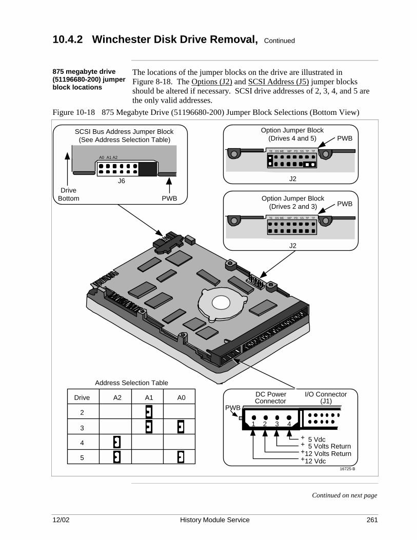
12/02 History Module Service 261
10.4.2 Winchester Disk Drive Removal, Continued
875 megabyte drive (51196680-200) jumper block locations
The locations of the jumper blocks on the drive are illustrated in Figure 8-18. The Options (J2) and SCSI Address (J5) jumper blocks should be altered if necessary. SCSI drive addresses of 2, 3, 4, and 5 are the only valid addresses.
Figure 10-18 875 Megabyte Drive (51196680-200) Jumper Block Selections (Bottom View)
Drive A2 A1 A0
2
3
4
5
SCSI BusTerminationResistor Modules
(Pin 1)
SCSI Bus Address Jumper Block(See Address Selection Table)
DriveBottom
J6
PWB
DC PowerConnector
1 2 3 4
PWB
I/O Connector(J1)
+ 5 Vdc+ 5 Volts Return+12 Volts Return+12 Vdc
PWB
TE DS ME WP PD SS TP TP
J2
Option Jumper Block(Drives 2 and 3)
PWBTE DS ME WP PD SS TP TP
J2
Option Jumper Block(Drives 4 and 5)
16725-B
Address Selection Table
A2A1A0
Continued on next page

12/02 History Module Service 262
10.4.2 Winchester Disk Drive Removal, Continued
875 megabyte drive (51196680-200) SCSI bus termination
Unlike the 210 and 445 megabyte drives, the 875 megabyte drive, 51196680-200, does not accommodate external SCSI bus termination modules on the bottom of the drive. Bus terminators are permanently located on the drive’s PWB and activated by jumpers on the Option (J2) jumper block as illustrated in Figure 10-18. The SCSI bus terminators must be enabled on any drive that is mounted in the front position of the Winchester Drive Tray. A drive mounted in the rear position on a tray must never have its bus terminators enabled. The modules provide end termination for the SCSI bus when the Winchester Drive Tray is present. With the tray removed, resistor terminators on the Winchester Drive Interface (WDI) circuit board in the Winchester Dive Assembly provide the bus termination.
1.8 gigabyte drive jumper blocks
Figure 10-19 is an illustration of the 1.8 gigabyte Winchester hard-disk drive, showing the locations of the various jumper blocks. All of the jumper blocks should be checked for proper positioning of the jumpers, based upon the drive’s mounting location on a tray. Two jumper blocks must be altered, if necessary, to accommodate the mounting location of the drive on either a right-hand or left-hand tray, front or rear position. These are the Option Select (J2) and SCSI Address (J6) jumper blocks. Table 10-5 and Figure 10-19 illustrate the proper positioning of the jumpers on both jumper blocks (J2 and J6) for the drive’s mounting position. Table 10-5 1.8 Gigabyte Drive SCSI Device Address Selection
Device Tray Location
SCSI Device Address Jumper Position
Left-Hand Rear 2 2
Right-Hand Rear 3 1 and 2
Left-Hand Front 4 3
Right-Hand Front 5 * 1 and 3
* Replacement drives are shipped from the factory pinned for a SCSI device address of 5.
Continued on next page

12/02 History Module Service 263
10.4.2 Winchester Disk Drive Replacement, Continued
1.8 gigabyte drive jumper block locations
The locations of the jumper blocks on the drive are illustrated in Figure 10-19. The Options Select (J2) and SCSI Address (J6) jumper blocks should be altered as appropriate. SCSI drive addresses of 2, 3, 4, and 5 are the only valid addresses.
Figure 10-19 1.8 Gigabyte Drive Jumper Block Selections (Bottom View)
Drive A2 A1 A0
2
3
4
5
SCSI BusTerminationResistor Modules
(Pin 1)
SCSI Bus Address Jumper Block(See Address Selection Table)
DriveBottom
J6
PWB
DC PowerConnector
1 2 3 4
PWB
I/O Connector(J1)
+ 5 Vdc+ 5 Volts Return+12 Volts Return+12 Vdc
PWB
TE DS ME WP PD SS TP TP
J2
Option Jumper Block(Drives 2 and 3)
PWB
TE DS ME WP PD SS TP TP
J2
Option Jumper Block(Drives 4 and 5)
16725-B
Address Selection Table
A2A1A0
Continued on next page
12/02 History Module Service 264
10.4.2 Winchester Disk Drive Replacement, Continued
1.8 gigabyte drive SCSI bus termination
Unlike the 210 MB and 445 megabyte drives, the 1.8 gigabyte drive does not accommodate external SCSI bus termination modules on the bottom of the drive. Bus terminators are permanently located on the drive’s PWB and activated by jumpers on the Option Select (J2) jumper block as illustrated in Figure 10-19. The SCSI bus terminators must be enabled on any drive that is mounted in the front position of the Winchester Drive Tray. A drive mounted in the rear position on a tray must never have its bus terminators enabled. The modules provide end termination for the SCSI bus when the Winchester Drive Tray is present. With the tray removed, resistor terminators on the Winchester Drive Interface (WDI) circuit board in the Winchester Dive Assembly provide the bus termination.
Winchester disk drive installation
Before mounting the drive, be sure that it is pinned correctly and has bus termination modules installed if the drive will be mounted at the front position on the tray. The SCSI bus address and SCSI bus termination module information was discussed previously in this subsection. Place the tray in an upright position. Grasp the printed flex-circuit connector and move the drive to the connector. Do not grasp the printed flex-circuit itself. Connect the power cable connector to its mating connector on the drive. Both connectors are held in place by the mated connection friction. There are no connector retainers. Hold the drive you are installing in place with your hand and invert the tray, so that the tray is resting on the drive. Reposition the tray carefully, so that the desired set of drive mounting holes (front or rear) align with the four tapped holes at the bottom of the drive as illustrated in Figure 10-20 for the 210 megabyte drive. Figure 10-21 illustrates the 445 MB, 875 MB, and 1.8 GB drives. They are similar in appearance. If the tray does not have another drive already mounted on it, you will have to support one end of the tray while you tighten the screws. Install only the three Phillips-head screws as illustrated in Figure 10-19 or 10-20. Only three screws are used to accommodate any warpage in the tray’s construction affecting the drive.
Continued on next page

12/02 History Module Service 265
10.4.2 Winchester Disk Drive Replacement, Continued
210 MB drive mounting
Figure 10-20 210 Megabyte Drive Mounting
6760
445/875 MB and 1.8 GB drive mounting
Figure 10-21 445/875 Megabyte and 1.8 Gigabyte Drive Mounting
12491
Rear Side of Drive (Connector Side)
6 - 32 1/4 Inch Screws

12/02 History Module Service 266

12/02 History Module Service 267
Section 11 – Dual Logical WDA History Module Assembly
11.1 Overview
Section contents The topics covered in this section are:
Topic See Page 11.1 Overview 291 11.2 History Module Assembly 293 11.2.1 General Assembly 293 11.2.2 Fan Assembly Replacement 294 11.2.3 Power Supply Replacement 294 11.2.4 Circuit Board Replacement 295 11.2.5 Cabling Replacement 304 11.2.6 Winchester Disk Assembly Replacement 305 11.3 Winchester Disk Assembly Reassembly 306 11.4 Winchester Drive Tray Assembly 307 11.4.1 General Information 307 11.4.2 Winchester Disk Drive Replacement 309
Purpose This section describes the assembly of the WDA History Module with
major components that includes the circuit boards, Winchester Disk Assembly, Winchester disk drive(s), power supply, fan assembly, and the module cabling.
Reference Refer to the Five/Ten-Slot Module Service manual for assembly
procedures where applicable. In particular, the installation of the K2LCN or K4LCN circuit board and its associated I/O circuit board, the LCN I/O (CLCN A/B), is detailed in the Five/Ten-Slot Module Service manual. All the other circuit boards used in the WDA History Module, other than the Smart Peripheral Controller (SPC) circuit board, are unique to the WDA History Module.
Continued on next page

12/02 History Module Service 268
11.1 Overview, Continued
History Module description
The Winchester Disk Assembly that occupies the upper two card slot locations in the module chassis can contain two Winchester Drive Trays. The trays are physically and electrically identical except for the number of drives the tray contains. Depending on the History Module configuration, one or two Winchester disk drives are mounted on the tray. See Section 2 for a description of the allowable drive configurations. A nonredundant History Module will have a single drive mounted on the right-hand tray. The left-hand tray will be absent. A redundant History Module will have a single drive mounted on both the right-hand and left-hand trays. The number of drives and their orientation must be the same on each tray. A tray can be installed in the Winchester Disk Assembly while power is applied to the History Module (the power supply’s ON/OFF switch is in the ON position). However, the tray’s ON/OFF switch must be in the OFF position when installing the tray.
CAUTION CAUTION—Always follow proper ESD (Electrostatic Discharge) procedures when handling circuit boards and other electronic components.
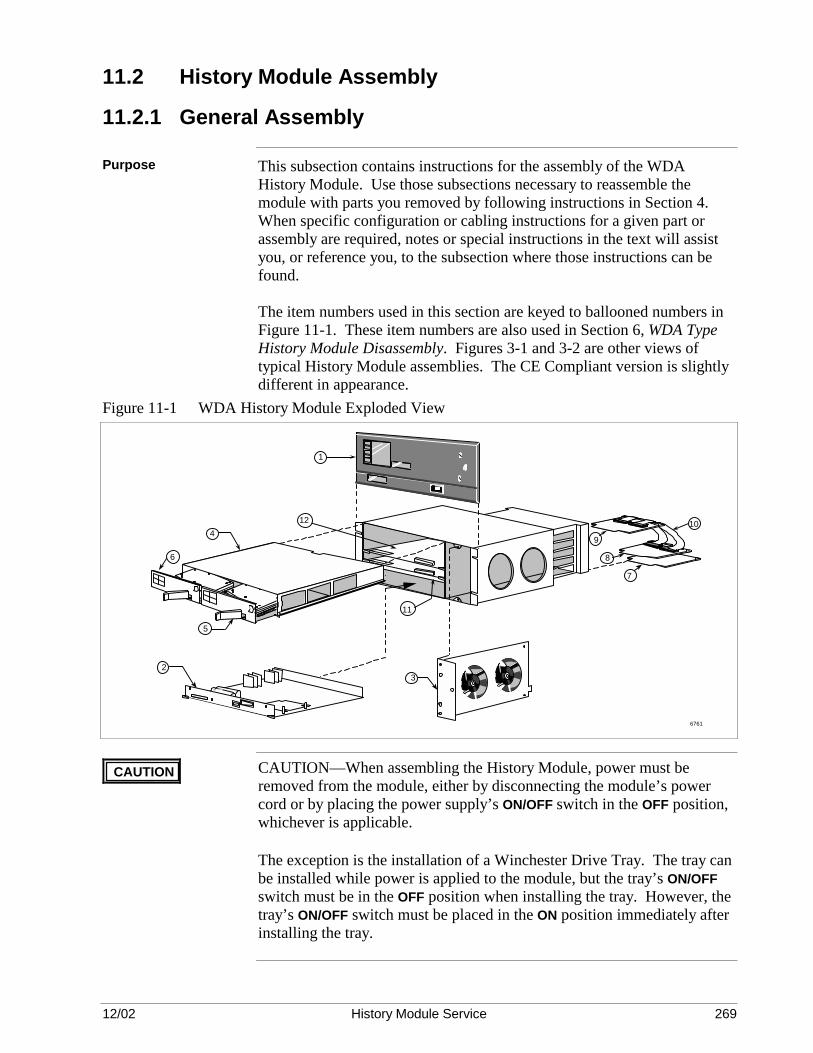
12/02 History Module Service 269
11.2 History Module Assembly
11.2.1 General Assembly
Purpose This subsection contains instructions for the assembly of the WDA History Module. Use those subsections necessary to reassemble the module with parts you removed by following instructions in Section 4. When specific configuration or cabling instructions for a given part or assembly are required, notes or special instructions in the text will assist you, or reference you, to the subsection where those instructions can be found. The item numbers used in this section are keyed to ballooned numbers in Figure 11-1. These item numbers are also used in Section 6, WDA Type History Module Disassembly. Figures 3-1 and 3-2 are other views of typical History Module assemblies. The CE Compliant version is slightly different in appearance.
Figure 11-1 WDA History Module Exploded View
6761
1
23
10
7
5
6
49
8
12
11
CAUTION CAUTION—When assembling the History Module, power must be removed from the module, either by disconnecting the module’s power cord or by placing the power supply’s ON/OFF switch in the OFF position, whichever is applicable.
The exception is the installation of a Winchester Drive Tray. The tray can be installed while power is applied to the module, but the tray’s ON/OFF switch must be in the OFF position when installing the tray. However, the tray’s ON/OFF switch must be placed in the ON position immediately after installing the tray.

12/02 History Module Service 270
11.2.2 Fan Assembly Replacement
Assembly procedure Slide the fan assembly (3) into the chassis, being careful that the connector
at the rear of the assembly mates properly. Secure the fan assembly with the two fasteners.
11.2.3 Power Supply Replacement
Assembly procedure Be sure the power supply’s ON/OFF switch is in the OFF position. Slide
the power supply (2) into the module until it begins to mate with its backpanel connectors. Then press on the extractor levers located on each side of the assembly until the power supply is fully mated with the backpanel connectors.
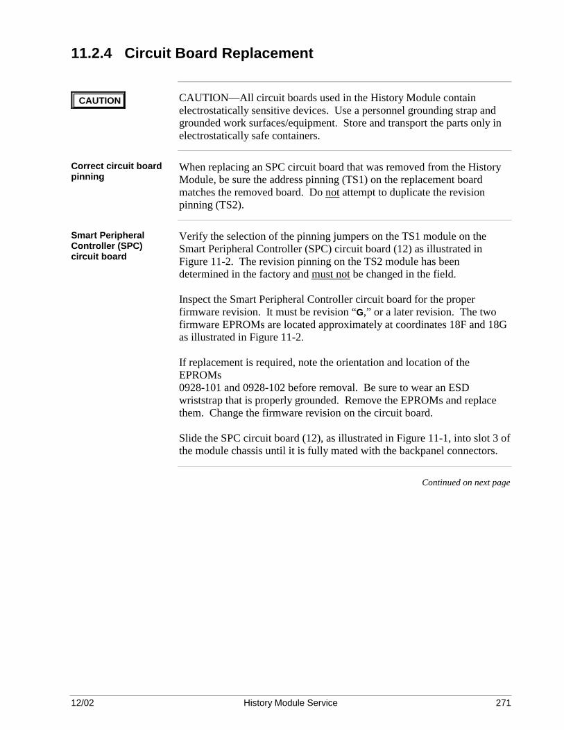
12/02 History Module Service 271
11.2.4 Circuit Board Replacement
CAUTION CAUTION—All circuit boards used in the History Module contain electrostatically sensitive devices. Use a personnel grounding strap and grounded work surfaces/equipment. Store and transport the parts only in electrostatically safe containers.
Correct circuit board pinning
When replacing an SPC circuit board that was removed from the History Module, be sure the address pinning (TS1) on the replacement board matches the removed board. Do not attempt to duplicate the revision pinning (TS2).
Smart Peripheral Controller (SPC) circuit board
Verify the selection of the pinning jumpers on the TS1 module on the Smart Peripheral Controller (SPC) circuit board (12) as illustrated in Figure 11-2. The revision pinning on the TS2 module has been determined in the factory and must not be changed in the field. Inspect the Smart Peripheral Controller circuit board for the proper firmware revision. It must be revision “G,” or a later revision. The two firmware EPROMs are located approximately at coordinates 18F and 18G as illustrated in Figure 11-2. If replacement is required, note the orientation and location of the EPROMs 0928-101 and 0928-102 before removal. Be sure to wear an ESD wriststrap that is properly grounded. Remove the EPROMs and replace them. Change the firmware revision on the circuit board. Slide the SPC circuit board (12), as illustrated in Figure 11-1, into slot 3 of the module chassis until it is fully mated with the backpanel connectors.
Continued on next page

12/02 History Module Service 272
11.2.4 Circuit Board Replacement, Continued
SPC circuit board SCSI bus address pinning
Figure 11-2 SCSI Bus Address Pinning on SPC Circuit Board
TS2
TS1
Board Revision Socket DO NOT CHANGE
Configure TS1 as follows: PINS DESCRIPTION 9-8 Always Shorted 10-7 Always Shorted 11-6 Always Shorted 12-5 Always Shorted 13-4 Short = WREN III or WDA History Module * 14-3 Open ** 15-2 Open ** 16-1 Open ** * = Setting for this application ** = SCSI Address 7 for this application
SPCASSY No.51401052-100
ADDR REV
910111213141516
87654321
0928
-101
REV
. G09
28-1
02R
EV. G
0928
-102
0928
-101
12554
SPC II (SPC2) I/O circuit board
The SPC II (SPC2) I/O circuit board (8) is associated with the SPC circuit board and is installed in slot 2 of the rear card cage as illustrated in Figure 11-1. Slide the SPCII I/O circuit board into the slot until fully mated with the backpanel connectors. There are no pinning requirements on the board.
Continued on next page

12/02 History Module Service 273
11.2.4 Circuit Board Replacement, Continued
LCN address configuration
The LCN node address can be selected on either the K2LCN (K4LCN) circuit board or the LCN I/O (CLCN A/B) board. Configuring the LCN node address on the K2LCN (K4LCN) circuit board is preferred for consistency, but selecting the address on either circuit board is acceptable. However, all the jumpers on the circuit board that is not being used for address selection must be removed, or if the board uses configuration switches as a substitute for the jumpers, the switches must be placed in their zero (0) position.
K2LCN circuit board LCN node address selection
The early production and current production K2LCN circuit boards (11), as illustrated in Figures 11-3 and 11-4, have an LCN node address pinning module at coordinate 9C and 7A, respectively. Pin the K2LCN board for the appropriate LCN node address. All jumpers on the LCN I/O circuit board must be removed if the LCN address is selected on the K2LCN circuit board. If a CLCN A/B is present, its configuration switches must be in their zero (0) position. The early production and current production K4LCN circuit boards (11), as illustrated in Figures 11-5 and 11-6, have an LCN node address pinning module, TS2, at locations 21E and 7A, respectively. Pin the K4LCN board for the appropriate LCN node address. All jumpers on the LCN I/O circuit board must be removed if the LCN address is selected on the K4LCN circuit board. If a CLCN A/B board is present, its configuration switches must be in their zero (0) position. As illustrated in Figure 11-1, slide the K2LCN or K4LCN circuit board (11) into slot 1 until it is fully mated with the backpanel connectors after selecting the appropriate LCN node address.
Continued on next page

12/02 History Module Service 274
11.2.4 Circuit Board Replacement, Continued
K2LCN (51401551-x00) LCN address selection
Figure 11-3 illustrates LCN node address selection on the K2LCN board, assembly 51401551-x00. The pinning block, TS2, is located at coordinate 9C on the board. The absence of a jumper is a binary “1.” Parity must be an odd number.
Figure 11-3 K2LCN Board (51401551-x00) LCN Node Address Selection
9D
9F
9H
9C
TS2
Jumper Removed = "1"
P
64
32
16
8
4
2
1
Binary Weight Parity
9467
65
43
21
0NOTE: This text is not on the board.
K2LCN
Continued on next page

12/02 History Module Service 275
11.2.4 Circuit Board Replacement, Continued
K2LCN (51402615-x00) LCN address selection
Figure 11-4 illustrates LCN node address selection on the K2LCN board, assembly 51402615-x00. The pinning block, TS1, is located at coordinate 7A on the board. The absence of a jumper is a binary “1.” Parity must be an odd number.
Figure 11-4 K2LCN Board (51402615-x00) LCN Node Address Selection
4C
8H3H
7A
TS1
Jumper Removed = "1" The overall number of jumpers removed, including the parity jumper, must be an odd number. This example indicates node address 03.
7739
NOTE: This text is not on the board.
K2LCN
P
64
32
16
8
4
2
1
Binary Weight Parity
65
43
21
0
Continued on next page

12/02 History Module Service 276
11.2.4 Circuit Board Replacement, Continued
K4LCN (51401946-100) LCN address selection
Figure 11-5 illustrates LCN node address selection on the K4LCN board, assembly 51401946-100. The pinning block, TS2, is located at coordinate 21E on the board. The absence of a jumper is a binary “1.” Parity must be an odd number.
Figure 11-5 K4LCN Board (51401946-100) LCN Node Address Selection
LCN Address Pinning
Jumper Out = 1 Jumper In = 0
NOT ON BOARD
PARITY 64
32
16
8 4
2
11 0
01
23
45
6P
LCN
AD
DR
ESS
The overall number of jumpers out, including the parity jumper, must be an odd number.
BINARY WEIGHT
The 1 and 0 refer to DIP switch positions when a switch assembly is installed in place of the jumper block.
Note that addresses 0-127 could be set, but software will allow only node addresses 1-64.
This Sample is 43:
51081
Continued on next page
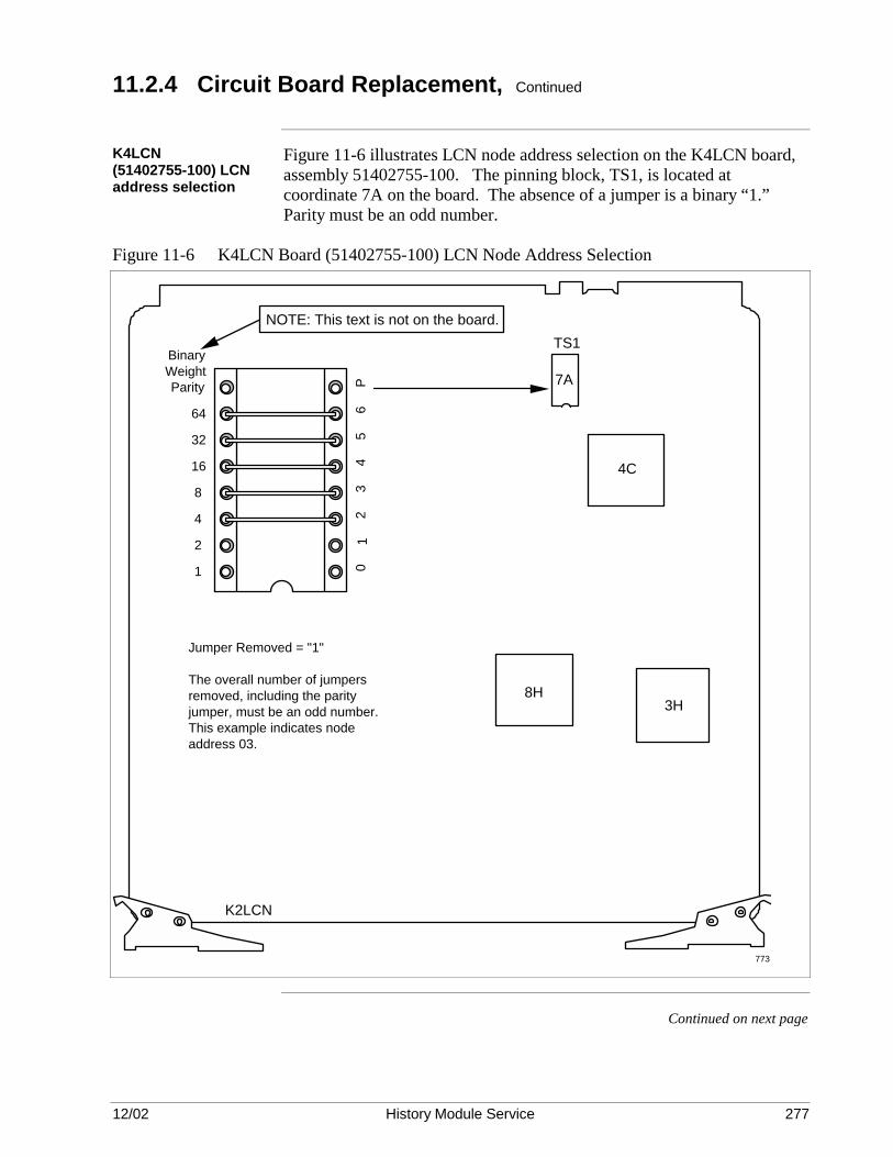
12/02 History Module Service 277
11.2.4 Circuit Board Replacement, Continued
K4LCN (51402755-100) LCN address selection
Figure 11-6 illustrates LCN node address selection on the K4LCN board, assembly 51402755-100. The pinning block, TS1, is located at coordinate 7A on the board. The absence of a jumper is a binary “1.” Parity must be an odd number.
Figure 11-6 K4LCN Board (51402755-100) LCN Node Address Selection
4C
8H3H
7A
TS1
Jumper Removed = "1" The overall number of jumpers removed, including the parity jumper, must be an odd number. This example indicates node address 03.
773
NOTE: This text is not on the board.
K2LCN
P
64
32
16
8
4
2
1
Binary Weight Parity
65
43
21
0
Continued on next page
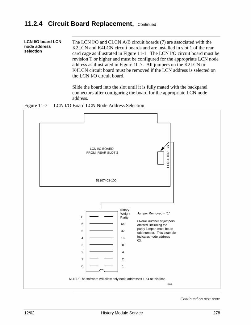
12/02 History Module Service 278
11.2.4 Circuit Board Replacement, Continued
LCN I/O board LCN node address selection
The LCN I/O and CLCN A/B circuit boards (7) are associated with the K2LCN and K4LCN circuit boards and are installed in slot 1 of the rear card cage as illustrated in Figure 11-1. The LCN I/O circuit board must be revision T or higher and must be configured for the appropriate LCN node address as illustrated in Figure 10-7. All jumpers on the K2LCN or K4LCN circuit board must be removed if the LCN address is selected on the LCN I/O circuit board. Slide the board into the slot until it is fully mated with the backpanel connectors after configuring the board for the appropriate LCN node address.
Figure 11-7 LCN I/O Board LCN Node Address Selection
Jumper Removed = "1" Overall number of jumpers omitted, including the parity jumper, must be an odd number. This example indicates node address 03.
The software will allow only node addresses 1-64 at this time.NOTE:
0
1
2
3
4
5
6
P
1
2
4
8
16
32
64
Binary Weight Parity
LCN
AD
DR
ESS
51107403-100
LCN I/O BOARD FROM REAR SLOT 2
2923
Continued on next page

12/02 History Module Service 279
11.2.4 Circuit Board Replacement, Continued
CLCN A/B board LCN node address selection
The CLCN A/B board is the CE Compliant version of the LCN I/O board. Figure 11-8 illustrates LCN node address selection on the CLCN A/B board. The figure illustrates an LCN node address of seven (7). Placing a switch in the zero (0) position is a binary “1.” Parity must be an odd number. Slide the board into the slot until it is fully mated with the backpanel connectors after configuring the board for the appropriate LCN node address.
Figure 11-8 CLCN A/B Board LCN Node Address Selection
BAR
CO
DE
ASSY NO. 51305072-100 REV A
LCN A
J1
LCN B
J2 1 0
0123456P
LCN Address
ON
12
34
56
78
16749
Continued on next page

12/02 History Module Service 280
11.2.4 Circuit Board Replacement, Continued
WDI I/O circuit board The WDI I/O circuit board (9) is associated with the Winchester Drive
Interface (WDI) circuit board located in the Winchester Disk Assembly (4) and is installed in slot 5 of the rear card cage as illustrated in Figure 11-1. There are no pinning requirements on the circuit board. Slide the board into the slot until it is fully mated with the backpanel connectors.
11.2.5 Cabling Replacement
Overview The History Module requires the connection of two external cable sets to
service its two interfaces. The interfaces are described below.
Winchester drive interface
An interface between the SPCII (SPC2) I/O circuit board (8), located in slot 2 of the History Module’s rear card cage, and the WDI I/O circuit board (9), located in slot 5 of the rear card cage, is provided by two 50-pin ribbon cables (10). The interface is the SCSI bus interface between the SPC circuit board (12) and any Winchester disk drives mounted on the Winchester Drive Trays (5 and 6) in the Winchester Disk Assembly. The sets of ribbon cable connectors are keyed and friction-mate with connectors on the SPCII (SPC2) I/O and WDI I/O circuit boards as illustrated in Figure 11-1. Do not grasp the ribbon cable when making the connection. Grasp only the ribbon cable connectors.
Local Control Network interface
Two coaxial trunk cables, A and B, provide the interface to the Local Control Network (LCN). The trunk cables are color coded, with cable A coded yellow, and cable B coded green. The connections to the LCN (CLCN A/B) I/O circuit board (7), located in slot 1 of the module’s rear card cage, are made with tee connectors. Connect the LCN trunk cables, noting the identification labels and color codes on the cables. Match the cables to the proper connector on the LCN I/O circuit board. Do not cross-connect the cable connections.

12/02 History Module Service 281
11.2.6 Winchester Disk Assembly Replacement
WDA replacement As illustrated in Figure 11-1, the Winchester Disk Assembly (4) occupies
slots 4 and 5 in the History Module chassis. Figure 11-9 is an illustration of the assembly. The Winchester Disk Assembly connectors mate with the backpanel connectors in the slot 5 position, but is guided into position by the circuit board guide rails for the slot 4 position. Grasping the metal partition dividing the tray compartments, with the tray(s) disengaged or removed, is a convenient way of inserting the assembly into its backpanel connectors. The friction of the backpanel connectors tends to hold the assembly in place. However, two fasteners, located toward the front of each side of the assembly, secure it in place. The fan assembly must be removed to have access for the right-hand side fastener. Figure 11-9 Winchester Disk Assembly
6770

12/02 History Module Service 282
11.3 Winchester Disk Assembly Reassembly
Description As illustrated in the exploded view of the Winchester Disk Assembly, Figure 11-10, the assembly is composed of a chassis (1), a Winchester Drive Interface (WDI) circuit board (2), and one or two Winchester Drive Trays, right-hand (3) and left-hand (4), that reside in the chassis. The trays are physically interchangeable assemblies, but must be properly configured for their application in the History Module. Refer to subsection 11.4. Figure 11-10 Winchester Disk Assembly Exploded View
WDI Circuit Board
6771
1
2
3
4
Tray removal and replacement
Each tray (3 or 4) is held in place by an extractor lever and by the friction of the tray’s mating connectors. The tray is removed from the assembly by pulling outward on the tray’s extractor lever and sliding the tray out of the chassis.
WDI circuit board The Winchester Drive Interface (WDI ) circuit board (2) is installed with five phillips-head screws at the corners and forward center of the board that are accessible through holes at the top of the assembly chassis. A 1.27-mm (.050-inch) spacer (washer) must be used between the circuit board and the metal chassis at each screw location. It is very important that the spacers are used in mounting the board, because without the spacers the board will not properly mate with the backpanel connectors. Since it is very difficult to install the WDI circuit board using spacers, it is recommended that the circuit board not be replaced in the field. Instead, the Winchester Disk Assembly should be replaced if it is suspected that the circuit board has failed.
Tray installation A Winchester Drive Tray (3 or 4) is installed in the assembly by gently sliding it into its compartment until it begins to mate with the WDI board. Then firmly apply pressure to the front of the tray until the extractor lever assumes a relaxed position that is parallel to the tray’s front panel.
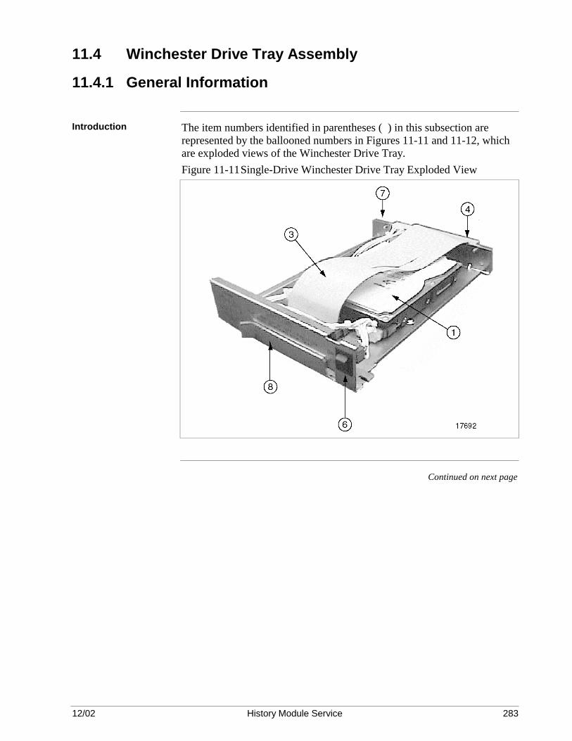
12/02 History Module Service 283
11.4 Winchester Drive Tray Assembly
11.4.1 General Information
Introduction The item numbers identified in parentheses ( ) in this subsection are
represented by the ballooned numbers in Figures 11-11 and 11-12, which are exploded views of the Winchester Drive Tray. Figure 11-11 Single-Drive Winchester Drive Tray Exploded View
Continued on next page

12/02 History Module Service 284
11.4.1 General Information, Continued
Description A Winchester Drive Tray consists of the following components: • One Winchester ST39175LW disk drive. • A ribbon cable (3) interconnects the drive(s) with the tray connector (4)
that interfaces to the WDI circuit board in the Winchester Disk Assembly. The ribbon cable provides the SCSI bus interface to the drive.
• A power ON/OFF switch (6) to control power from the power supply to
the drive(s) and SCSI bus terminators on the WDI circuit board in the Winchester Disk Assembly. When power is removed from the tray, SCSI bus terminators are activated on the WDI circuit board in anticipation of the loss of the bus terminators installed on a Winchester disk drive in the tray that is about to be removed. Terminators are installed on the drive that is mounted at the front of tray.
• A tray power connector (7) that interfaces to the WDI circuit board in
the Winchester Disk Assembly and provides +5 Vdc, +12 Vdc, and ground return to the drive(s) from the power supply.
• An extractor lever (8) used to both lock the tray in place in the
Winchester Disk Assembly and assist in extracting the tray when it is in place.
Disk drive SCSI bus termination
The SCSI cable is terminated by a termination modle attached to the drive end of the SCSI interface cable.

12/02 History Module Service 285
11.4.2 Winchester Disk Drive Replacement
Introduction A Dual Logical WDA hard drive tray can be used to replace the older
WDA drive tray that has 8.75 MB or 1.8 GB drives. Because it is always a single drive tray that is partitioned into dual drives, it is a direct replacement for single and dual drive redundant and non-redundant drive trays. When replacing a Seagate ST39175LWDrive with a new one, it must be pinned exactly like the old one. The SCSI cable is terminated by a termination module attached to the drive end of the SCSI interface cable. The drive has a self-locking protective mechanism that is activated when power is removed from the drive. However, the drive must be handled with care.
Disk drive SCSI bus termination
The SCSI cable is terminated by a termination module attached to the drive end of the SCSI interface cable.
ST39175LW hard-disk drive pinning
Figure 4-4 is an illustration of the partitioned Winchester ST39175LW hard-disk drive. The SCSI address pinning is 5 (for the primary drive tray) or 4 (for the redundant Drive tray).
Continued on next page

12/02 History Module Service 286
11.4.2 Winchester Disk Drive Removal, Continued
Winchester ST39175LW drive jumper block locations
The locations of the jumper blocks on the drive are illustrated in Figure 11-12. Only the J2 and J5 should have pinning, remove any pinning from J6. SCSI drive addresses of 4 and 5 are valid addresses. Address 5 is the address for the primary drive and 4 is the address for the redundant drive.
Figure 11-12 Winchester ST39175LW Drive Pinning

12/02 History Module Service 287
Section 12 – Startup
12.1 Overview
Section contents The topics covered in this section are:
Topic See Page 12.1 Overview 311 12.2 Visual Checks 311 12.2.1 WREN Type History Module 311 12.2.2 WDA Type History Module 312 12.3 Power-on Procedure 313 12.3.1 Component Replacement Startup 314 12.3.2 Nonredundant Drive Replacement Startup 316 12.3.3 Redundant Drive Replacement Startup 318 12.4 Redundant Disk Drive Data Synchronization 318 12.5 Winchester Disk Drive Formatting 320 12.5.1 Drive Formatting Procedure 321
Purpose This section provides an orderly startup procedure to use after installation
or repair of the History Module. It begins with a visual checkout and concludes with the results of applying power to the History Module.
12.2 Visual Checks
12.2.1 WREN Type History Module
Remove the front panel
Remove the front cover of the Winchester module and check to ensure that it is free of foreign matter and dirt accumulation. Be sure that all connections are proper and tight.
Check the circuit boards
Check that all circuit boards are installed in their assigned module slots and properly seated. Refer to the Five/Ten-Slot Module Service or Dual Node Module Service manuals for the circuit board assignments.
Check the LCN coax cables
Check to be sure that the Local Control Network (LCN) trunk cables are properly connected to the LCN I/O (CLCN A/B) circuit board and not cross-connected. Cable A (yellow) must be connected to the A connector, and cable B (green) must be connected to the B connector.
Check the LCN node address jumpers
Check that the address jumpers on the LCN I/O board or switches on the CLCN A/B board are correct for the LCN node selection.

12/02 History Module Service 288
12.2.2 WDA Type History Module
Remove the front panel
Remove the front panel of the WDA History Module so that you have access to the Winchester Drive Tray power ON/OFF switch(es).
Check the trays If a Winchester Drive Tray was removed to replace a defective drive, be
sure the drive is properly pinned for the drive’s location on the tray (right-hand or left-hand tray). If you are not sure that the front drive on a tray has three SCSI bus termination modules installed on the bottom of the drive, you will have to remove the drive to verify their presence. Ensure that the trays are locked in position. The tray’s extractor lever should be in its relaxed position, which is parallel to the front of the tray. Place each tray’s power ON/OFF switch in the ON position.
Check the circuit boards
Check that all circuit boards are installed in their assigned module slots and properly seated. Figure 3-1, 3-2, 6-1, and 11-1 illustrate the circuit board assignments.
Check the SCSI bus ribbon cables
Check that the two ribbon cables between the SPCII I/O and WDI I/O circuit boards are in place and secure.
Check the LCN coax cables
Check to be sure that the Local Control Network (LCN) trunk cables are properly connected to the LCN I/O (CLCN A/B) circuit board and not cross-connected. Cable A (yellow) must be connected to the A connector, and cable B (green) must be connected to the B connector.
Check the LCN address jumpers
Check that the address jumpers (switches) on the K2LCN (K4LCN) or LCN I/O (CLCN A/B) circuit board are correct for the LCN node selection. Only one of the two circuit boards must be pinned. Be sure the other circuit board has no address jumpers.
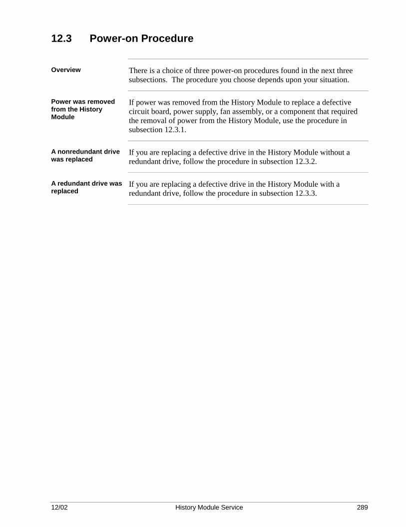
12/02 History Module Service 289
12.3 Power-on Procedure
Overview There is a choice of three power-on procedures found in the next three
subsections. The procedure you choose depends upon your situation.
Power was removed from the History Module
If power was removed from the History Module to replace a defective circuit board, power supply, fan assembly, or a component that required the removal of power from the History Module, use the procedure in subsection 12.3.1.
A nonredundant drive was replaced
If you are replacing a defective drive in the History Module without a redundant drive, follow the procedure in subsection 12.3.2.
A redundant drive was replaced
If you are replacing a defective drive in the History Module with a redundant drive, follow the procedure in subsection 12.3.3.

12/02 History Module Service 290
12.3.1 Component Replacement Startup
WREN type HM startup procedure
Use the procedure in Table 12-1 to restart a WREN type History Module after replacing a defective component, other than a drive. Power was removed from the History Module. Table 12-1 Restarting a WREN Type History Module Procedure – Component Replacement
Step Action
1 In the Winchester Drive Module(s), place the drive power supply’s AC POWER switch in the 1 (ON) position. The green LED on the power supply should be lit. Check that the red LED on the fan assembly is not lit. Secure the cover(s) to the module(s).
2 Place the POWER switch on the electronics module in the ON (1) position. Check that all red LEDs extinguish and all green LEDs illuminate within 1.5 minutes. Also, note the alphanumeric display and ensure that it displays the proper LCN node address for the History Module.
3 Verify that the History Module has autobooted properly and that its data is valid. Examine the status of the History Module at the Universal Station and test for History Module related activities. If the data is not valid, continue with this procedure.
4 You must now initialize the History Module using the original NCF. See the Network Data Entry manual for details.
5 Restore the local volume and system software files.
6 Restore the Continuous History data. See subsection 7.7 in the Engineer’s Reference Manual.
7 Restore all other files. Refer to the Command Processor Operation manual.
8 After all of your files have been restored, autoboot the History Module by either doing a double-shutdown from the Universal Station, or by placing the electronics module’s power supply switch in the OFF (0) position for approximately 30 seconds, then back to the ON (1) position. If the autoboot is unsuccessful, go to the troubleshooting techniques in Section 5 or call TAC for assistance.
Continued on next page

12/02 History Module Service 291
12.3.1 Component Replacement Startup, Continued
WDA type HM startup procedure
Use the procedure in Table 12-2 to restart a WDA type History Module after replacing a defective component, other than a drive. Power was removed from the History Module. Table 12-2 Restarting a WDA Type History Module Procedure – Component Replacement
Step Action
1 Place the Winchester Drive Tray power switch(es) in the ON position. Place the power supply power ON/OFF switch in the ON position. Check that all red LEDs extinguish and that all green LEDs illuminate within approximately 1.5 minutes. Check that the alphanumeric display on the K2LCN/K4LCN circuit board shows the correct LCN node address for the History Module.
2 Verify that the History Module has autobooted properly and that its data is valid. Examine the status of the History Module at the Universal Station and test for History Module related activities. If the data is not valid, continue with this procedure.
3 You must now initialize the History Module using the original NCF. See the Network Data Entry manual for details.
4 Restore the local volume and system software files.
5 Restore the Continuous History data. See subsection 7.7 in the Engineer’s Reference Manual.
6 Restore all other files. Refer to the Command Processor Operation manual.
7 After all of your files have been restored, autoboot the History Module by either doing a double-shutdown from the Universal Station, or by placing the power supply’s ON/OFF switch in the OFF position for approximately 30 seconds, then back to the ON position. If the autoboot is unsuccessful, go to the troubleshooting techniques in Section 5 or call TAC for assistance.

12/02 History Module Service 292
12.3.2 Nonredundant Drive Replacement Startup
WREN type HM startup procedure
Use the procedure in Table 12-3, when replacing a nonredundant drive in a WREN type History Module. Table 12-3 Restarting a WREN Type History Module Procedure – Nonredundant Drive Replacement
Step Action
1 In the Winchester Drive Module, place the drive power supply’s AC POWER switch in the 1 (ON) position. The green LED on the power supply should be lit. Check that the red LED on the fan assembly is not lit. Secure the cover(s) to the module(s).
2 Place the POWER switch on the electronics module in the ON (1) position. Check that all red LEDs extinguish and all green LEDs illuminate within 1.5 minutes. Also, note the alphanumeric display and ensure that it displays the proper LCN node address for the History Module.
3 If you replaced a defective drive with a factory replacement, the drive has been formatted at the factory. If you replaced a defective drive with a drive previously used in another History Module, the drive must be reformatted. Reformat the drive using the procedure in subsection 12.5 before continuing.
4 You must now initialize the History Module using the original NCF you saved before the drive failed. See the Network Data Entry manual for the procedure.
5 Restore the local volume and system software files.
6 Restore the Continuous History Data. See subsection 7.7 in the Engineer’s Reference Manual.
7 Restore all other files. Refer to the Command Processor Operation manual.
8 After all of your files have been restored, autoboot the History Module by either doing a double-shutdown from the Universal Station, or by placing the electronics module’s power supply switch in the OFF (0) position for approximately 30 seconds, then back to the ON (1) position. If the autoboot is unsuccessful, go to the troubleshooting techniques in Section 5 or call TAC for assistance.
Continued on next page

12/02 History Module Service 293
12.3.2 Nonredundant Drive Replacement Startup, Continued
WDA type HM startup procedure
When replacing a nonredundant drive in a WDA type History Module, you had the option of removing power from the entire WDA History Module using the ON/OFF switch on the power supply, or remove power from the right-hand tray, using its power ON/OFF switch. Either method is acceptable. If you used the latter method, start at Step 2 in the procedure in Table 12-4. Table 12-4 Restarting a WDA Type History Module Procedure – Nonredundant Drive Replacement
Step Action
1 Set the Winchester Drive Tray power switch(es) in the ON position. Place the power supply ON/OFF switch in the ON position. Check that all red LEDs extinguish and that all green LEDs illuminate within approximately 1.5 minutes. Check that the alphanumeric display on the K2LCN circuit board shows the correct LCN node address for the History Module.
2 If you replaced a defective drive with a factory replacement, the drive has been formatted at the factory. If you replaced a defective drive with a drive previously used in another History Module, the drive must be reformatted. Reformat the drive using the procedure in subsection 12.5 before continuing.
3 You must now initialize the History Module using the original NCF you saved before the drive failed. See the Network Data Entry manual for the procedure.
4 Restore the local volume and system software files.
5 Restore the Continuous History Data. See subsection 7.7 in the Engineer’s Reference Manual.
6 Restore all other files. Refer to the Command Processor Operation manual.
7 After all of your files have been restored, autoboot the History Module by either doing a double-shutdown from the Universal Station, or by placing the power supply’s ON/OFF switch in the OFF position for approximately 30 seconds, then back to the ON position. If the autoboot is unsuccessful, go to the troubleshooting techniques in Section 5 or call TAC for assistance.

12/02 History Module Service 294
12.3.3 Redundant Drive Replacement Startup
WREN type HM startup procedure
Use the procedure in Table 12-5 when replacing a drive in a WREN type History Module that has a redundant partner. Table 12-5 Restarting a WREN Type History Module Procedure – Redundant Drive Replacement
Step Action
1 Power was removed from the Winchester Drive Module that housed the defective drive. Place the drive power supply’s AC POWER switch in the 1 (ON) position. The green LED on the power supply should be lit. Check that the red LED on the fan assembly is not lit. Secure the cover(s) to the module(s).
2 Perform the “data synchronization” procedure detailed in subsection 12.4. After the synchronization has been successfully completed, you will be on-line and in an operating state.
WDA type HM startup procedure
Use the procedure in Table 12-6 when replacing a drive in a WDA type History Module that has a redundant partner. Table 12-6 Restarting a WDA Type History Module Procedure – Redundant Drive Replacement
Step Action
1 Power was not removed from the History Module power supply. Instead, power was removed from the Winchester Drive Tray on which you replaced a drive. Place the tray’s power switch in the ON position after it is reinstalled.
2 Perform the “data synchronization” procedure detailed in subsection 12.4. After the synchronization has been successfully completed, you will be on-line and in an operating state.
12.4 Redundant Disk Drive Data Synchronization
Overview After a redundant drive has been replaced, the data on the disk must be
restored with data from its redundant partner by a synchronization process. That is, the drive must be structured by software to contain exactly the same data as its redundant partner, which has remained functional while the drive was being replaced.
Continued on next page

12/02 History Module Service 295
12.4 Redundant Disk Drive Data Synchronization, Continued
Data synchronization To synchronize the drives, perform the following steps in Table 12-7. Table 12-7 Redundant Drives Data Synchronization Procedure
Step Action 1 At a US, use the Engineering Personality Main Menu display to select
the SYSTEM STATUS target and examine the status of the HM you have serviced. The status should be SEVERE. This is a system indication that data synchronization has not been performed.
2 Select the Command Processor and issue a status request for the physical drive that you have replaced as follows: STA PN:XX (XX is the physical node number of the target HM) Examples of a printout for physical node 43 are as follows:
Device RedundantNode Peripheral Address Device Status System Name---- ---------- --------- --------- -------- -----------43 FIXED DISK 5 4 OFFLINE NONE43 FIXED DISK 4 5 OK NONE
The first display example of the status shows drive 5 as OFFLINE. Drive 4 is OK, it is operational. More than one drive can be OFFLINE.
Device RedundantNode Peripheral Address Device Status System Name---- ---------- --------- --------- -------- -----------43 FIXED DISK 5 4 NONE43 FIXED DISK 4 5 OK NONE
UNINITD
The second display example of the status shows drive 5 as UNINITD, meaning not initialized. Both drive status require that you execute the synchronization command.
3
Execute a data synchronization request for the OFFLINE or UNINITD drive(s): SYNCH PN:XX (XX is the physical node) The response “Synchronization was Initiated” should then be displayed. Synchronization takes at least 10 minutes. If another drive is also OFFLINE or in the UNINITD state, you can immediately issue the SYNCH request again for the other drive. If you do another status request (Step 2), you will receive a printout similar to the example for physical LCN node 43 as shown in Step 2. SYN_IP shows that synchronization is in progress. The printout is not periodically updated and must be displayed to check the progress of the synchronization. However, the History Module status on the System Status display is updated and changes from DISKPROB to OK when the synchronization has been successfully completed. Other status codes that you may see are: INITIALIZED – The device has been initialized NOT CREATED – The drive has not been formatted CORRUPTED – Formatting was unsuccessful
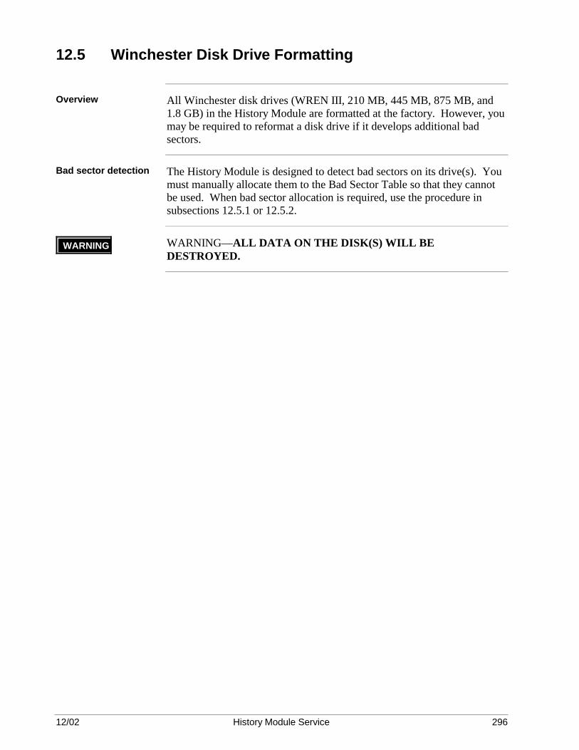
12/02 History Module Service 296
12.5 Winchester Disk Drive Formatting
Overview All Winchester disk drives (WREN III, 210 MB, 445 MB, 875 MB, and
1.8 GB) in the History Module are formatted at the factory. However, you may be required to reformat a disk drive if it develops additional bad sectors.
Bad sector detection The History Module is designed to detect bad sectors on its drive(s). You
must manually allocate them to the Bad Sector Table so that they cannot be used. When bad sector allocation is required, use the procedure in subsections 12.5.1 or 12.5.2.
WARNING WARNING—ALL DATA ON THE DISK(S) WILL BE DESTROYED.

12/02 History Module Service 297
12.5.1 Drive Formatting Procedure
CAUTION CAUTION—When reformatting an 875 megabyte drive (51196680-200) or 1.8 gigabyte drive (51196895-100), you must use a 10.8 or later release of HVTS.
Smart Controller Magnetic Disk tests
To reformat a drive, use the off-line Smart Controller Magnetic Disk (SCMD) tests described in the Hardware Verification Test System manual and referenced in the following discussion. Consult the reference for the detailed instructions required to run the test.
SCMD Test 21 overview
When properly configured, HVTS SCMD Test 21 will test the drive and print a list of defective Logical Block addresses before and after the test runs. If additional bad sectors are found, they will be identified and the blocks associated with them will be automatically reassigned.
SCMD Test 21 procedure
Use the procedure in Table 12-8 to run HVTS SCMD Test 21.
Table 12-8 HVTS SCMD Test 21 Procedure
Step Action
1 To load the disk-formatting software to the History Module, first load a Universal Station with HVTS. Then download HVTS to the History Module.
2 After loading HVTS to the selected History Module, press SELECT .
Answer the prompt that ends with ALL? with NOD XX ENTER where XX is the node number of the History Module. Now, press SELECT and answer the prompt with SET SCMD ENTER . The
program displays several functions that should have the parameters shown in Table 12-6. If they are correct, simply press ENTER . If
they must be changed, type in the change, then press ENTER .
3 After the last entry, press SELECT , then type MOD S and press
ENTER . Again, press SELECT , then type RUN and press
ENTER .
SCMD Test 21 will run, printing a list of defective Logical Block addresses before and after the test runs, and then the bad sectors will be reassigned. The Defect Data List display is in raw hex format because form and content of defective data varies depending on the drive vendor. Since detection and reassignment of bad sectors is automatic, the actual defective data printed is only of a casual concern to the user.
Continued on next page

12/02 History Module Service 298
12.5.1 Drive Formatting Procedure, Continued
SCMD Test 21 parameters
Table 12-9 SCMD Test 21 Parameters Function/Parameter Comment
DEVICE_0=NOT_IN_USEDEVICE_1=NOT_IN_USEDEVICE_2= DEVICE_3= DEVICE_4= DEVICE_5= DEVICE_6=NOT_IN_USEDEVICE_7=NOT_IN_USE
A nonredundant single drive is DEVICE_5 (SCSI address 5). Nonredundant dual drives are devices 5 and 3. Redundant single drives are devices 5 and 4. Redundant dual drives are devices 5, 4, 3, and 2. Identify the device(s) you want to format (you can enter more than one) by entering the parameter =W (abbreviation for WREN3_FMD) or =FMD (for 210/445/875 MB and 1.8 GB drives). List all other devices as =NOT_IN_USE if the drive address is not used or you do not want to access it.
ENTRY= Not applicable—press ENTER TESTS=21 Test 21 only ERROR_LIMIT=5 Report after the fifth error PASS_LIMIT=1 One pass through the test INHIBIT= Not applicable—press ENTER MINUTES_LIMIT=- Unlimited test time ABBREVIATION=4 Provide test help information
Function Parameters LIMIT_TESTING_TO_READ_ONLY= NO AVOID_WRITING_TO_RESERVED_DISKAREA=
NO
CLEAR_DEFECT_LIST= NO DISPLAY_DEFECT_LIST= BOTH MASTER_CONTROLLER_NODE_NUMBER= 0 ENABLE= FORMAT,
REASSIGN_DEFECTIVE_BLOCKS DISABLE= MANUAL_INTERVENTION_TESTS,
RESET_SCSI_BUS, CONTROLLERTOCONTROLLER_ TESTING, UTILITY_HELP
Continued on next page

12/02 History Module Service 299
12.5.1 Drive Formatting Procedure, Continued
SCMD Test 21 parameters, continued
Table 12-9 SCMD Test 21 Parameters, Continued Function/Parameter Comment
UDO= COMPARE_DATA, ERR_DISPLAY UDONT= STATUS_DISPLAY BLOCK_SIZE_IN_BYTES= 256 REPORT= TESTNUMBER, PASSNUMBER, LOG SCALE= 100

12/02 History Module Service 300

12/02 History Module Service 301
Section 13 – Spare Parts
13.1 Overview
Section contents The topics covered in this section are:
Topic See Page 113.1 Overview 325 13.2 Replaceable Parts Lists 325
Optimum Replaceable Unit (ORU)
In the parts list, Optimum Replaceable Unit (ORU) items are shown with an asterisk (*) beside the part.
13.2 Replaceable Parts Lists
Overview Refer to the Five/Ten-Slot Module Service or Dual Node Module Service
manual for ORU part numbers in the electronics module portion of the HM. In the parts lists, the Optimum Replaceable Unit (ORU) items are shown by an asterisk (*) beside the listing. Where appropriate, the item numbers in each parts list correspond to reference numbers in Figure 6-1 or 9-1 for a WREN type History Module and Figure 7-1 for a Type I WDA type History Module or 11-1 for a Type II WDA type History Module. Spare parts are listed by the original type of History Module that uses them (WREN or WDA). Go to the appropriate subsection listing the type of equipment that requires a replaceable part. The 210 megabyte, 445 megabyte, 875 megabyte, and 1.8 gigabyte Winchester disk drives are included in both the WREN and the 210/445/875 megabyte and 1.8 gigabyte parts list, because the WREN type of History Module can be upgraded to accommodate the 210 megabyte, 445 megabyte, 875 megabyte, or 1.8 gigabyte drive.
Continued on next page

12/02 History Module Service 302
13.2 Replaceable Parts Lists, Continued
WREN type History Module parts list
Table 13-1 lists part numbers for the WREN Winchester Drive Modules at the service-part level.
Table 13-1 WREN Type Drive History Module Parts List
Item Description Part Number
*1 Fan Assembly (includes fans) 51400646-100
2 Winchester Drive Module Power Cord, 120 Vac 51303421-092
2 Winchester Drive Module Power Cord, 240 Vac 51303629-092
3 Cable from Slide Tray Assembly Connector to Fan Assembly 51303549-100
* 4 Winchester Drive Module Power Supply 51107595-100
* 5 WREN III Hard Disk Drive 51195155-100
* 5 210 Megabyte Hard Disk Drive (includes installation instructions) 51196269-100
* 5 445 Megabyte Hard Disk Drive (includes installation instructions) 51196351-100
* 5 875 Megabyte Hard Disk Drive (includes installation instructions) 51196720-100
* 5 1.8 Gigabyte Hard Disk Drive (includes installation instructions) 51196897-100
6 Power Cable from Drive Power Supply to Disk Drives 51303536-061
Power Cable from Drive Power Supply to Fan Cable 51303625-019
7
SCSI Bus Ribbon Cable for single WREN III, 210/445/875 MB, or 1.8 GB Drive
51304191-100
7
SCSI Bus Ribbon Cable for dual WREN III, 210/445/875 MB, or 1.8 GB Drives
51304192-100
7
SCSI Bus Ribbon Cable for redundant single WREN III, 210/445/875 MB, or 1.8 GB Drives
51304193-100
7
SCSI Bus Ribbon Cable for redundant dual WREN III, 210/445/875 MB, or 1.8 GB Drives
51304194-100
* ORU level replacement item
Continued on next page

12/02 History Module Service 303
13.2 Replaceable Parts Lists, Continued
WDA type History Module parts list
Table 13-2 lists part numbers for the Winchester Disk Assembly type History Module at the service part level.
Table 13-2 WDA Type Drive History Module Parts List
Item Description Part Number
Five-Slot Module Assembly (w/o circuit boards, power supply, fan assy) * 51195499-100
* 3 Fan Assembly with fans for Five-Slot Module 51400646-100
* 2 Enhanced Power Supply for Five-Slot Module 51195066-100
Power Cord, 125 Vac, for Five-Slot Module 51303508-100
Power Cord, 250 Vac, for Five-Slot Module 51303508-200
1 Five-Slot Module Cover Assembly 51400918-100
* 4 WDA Chassis with Winchester Drive Interface (WDI) circuit board 51401930-100
5/6 Winchester Drive Tray (power cable, power switch, and printed flex-circuit) 51401929-300
* 210 Megabyte Disk Drive kit (includes installation instructions) 51196269-100
* 445 Megabyte Disk Drive kit (includes installation instructions) 51196351-100
* 875 Megabyte Disk Drive kit (includes installation instructions) 51196720-100
* 1.8 Gigabyte Disk Drive kit (includes installation instructions) 51196897-100
* Partioned WDA Winchbester Drive Tray 51403366-100
* Dual Logical Drive replacement for 1.8 GB disk drive 51191579-100
* Dual Logical Drive replacement for 875 MB disk drive 51191579-200
* 11 K2LCN-2 Circuit Board (with 2 megawords of memory) 51402615-200
* 11 K2LCN-4 Circuit Board (with 4 megawords of memory) 51402615-400
* 11 K4LCN Circuit Board 51401946-100
* 11 4-Megaword Memory Board for K4LCN Board (51401946-100) 51201645-400
* 11 K4LCN Circuit Board 51402755-100
* 11 4-Megaword Memory Board for K4LCN Board (51402755-100) 51201795-400
* 7 LCN I/O Circuit Board 51107403-100
* 7 CLCN A/B Circuit Board – CE Compliant 51305072-100
* 12 Smart Peripheral Controller (SPC) Circuit Board 51401052-100
* ORU Level Replacement Item
Continued on next page

12/02 History Module Service 304
13.2 Replaceable Parts Lists, Continued
WDA type History Module parts list, continued
Table 13-2 lists part numbers for the Winchester Disk Assembly type History Module at the service part level.
Table 13-2 WDA Type Drive History Module Parts List, Continued
Item Description Part Number
* 8 Smart Peripheral Controller II (SPCII) I/O Circuit Board 51304907-100
* 8 Smart Peripheral Controller II (SPC2) I/O Circuit Board – CE Compliant 51304907-200
* 9 Winchester Drive Interface (WDI) I/O Circuit Board 51304903-100
* 9 Winchester Drive Interface (WDI) I/O Circuit Board – CE Compliant 51304903-200
* 10 WDA SCSI Bus Interface Ribbon Cable 51304808-100
BNC T-Connector 51190728-105
* ORU Level Replacement Item

Index
12/02 History Module Service 305
+ +12 Vdc, 141, 169, 254, 288 +5 Vdc, 141, 169, 254, 288
5 50-pin ribbon cables, 250, 284
A Active Maintenance Journal, 91 Alphanumeric display, 85, 89 Alphanumeric display, 100 autoboot, 84, 101 autoboot, 87, 103
B backup copies of the data, 84 Bad Sector List, 98, 101, 110 Bad Sector List, 58, 103 Bad Sector Table, 300 bad sectors, 101, 103 block diagram, 48, 70
C cable removal, 127, 137, 165 cabling, 163, 237, 271 card cage, 250, 284 circuit board: configuration information, 52, 73 circuit board: pinning, 241, 275 circuit board indicators, 85 circuit boards, 163, 237, 271 coaxial T-connectors, 137, 165 connector hold-back bracket, 141 Continued on next page, 74 Continuous History data, 84 Control Track error, 112 CORRUPTED, 102, 105
D data synchronization, 58, 77 Defect Data List, 35 Defect Data List display, 301 defective blocks, 110 DEGRADED, 102, 106 Detailed Error Module message, 91
Index
12/02 History Module Service 306
disassembly, 123, 133, 140, 161, 168 DISKPROB, 139, 167 drive: maintenance, 35, 58, 77; pinning, 37, 59 drive: mounting, 144, 147, 150, 157, 255, 258, 261 Drive 2, 61, 78 Drive 3, 56 Drive 4, 59 Drive 5, 56, 74 drive tray interconnections, 55, 57, 60, 62, 76, 79 Dual drive configuration, 33 dual-drive tray, 141, 254
E electrical transients, 102 Electronics module configuration, 31 Electrostatic Discharge, 164, 238, 272 ELECTROSTATIC DISCHARGE (ESD), 82 EMPU/HMPU/HPK2/K2LCN/K4LCN, 85 Engineering Main Menu, 91 Engineering Personality Main Menu display, 121 ESD, 164, 238, 272 external cable, 250, 284 extractor lever, 141, 169
F failure indicators, 81 fan assembly, 45, 67, 85, 126, 136, 164, 163, 237, 271 fan assembly, 240, 274 Fan failure, 128 fast-load cartridges, 84 field adjustments, 20, 44, 63, 66, 80 flowchart, 87 front panel, 135, 163
G grounding strap, 141, 169
H Hardware Verification Test System, 81 History Module description, 238, 272 History Module Status display, 104, 108 HMI personality, 101, 107, 108 HMI personality, 104 HVTS, 105, 110 HVTS, 101 HVTS SCMD Test 21, 301

Index
12/02 History Module Service 307
I I/O card cage, 137, 165 initialization, 103 intermittent problem, 84
J jumper: block pinning, 142, 170 jumper: block pinning, 255; blocks, 144, 147, 150, 154, 157, 255, 258, 261, 264, 266 jumper blocks, 144, 147, 150, 154, 157, 255, 258, 261, 264, 266 jumpers, 144, 147, 150, 154, 157, 255, 258, 261, 264, 266
K K2LCN, 45, 67, 137, 165 K2LCN or K4LCN, 52, 73
L LCN, 137, 165, 250, 284 LCN: coax cables, 137, 165; node address, 85 LCN I/O, 137, 165 LOAD/DUMP, 104, 107, 108 Logical Block addresses, 301
M maintenance message abbreviations, 91 media defects, 102 modules, 146, 149, 153, 156, 159, 260, 263, 266, 268
N nonredundant drive failure, 101
O Object Detail (Volume Status) displays, 91 Object Detail display, 114 OFFLINE, 139, 167 Optimum Replaceable Unit, 305 ORU, 305 Overview, 21
P personnel grounding strap, 82, 135, 163 pinning, 142, 170, 255 pinning, 241, 275 power supply, 45, 67, 85, 135, 163, 237, 240, 271, 274

Index
12/02 History Module Service 308
power supply, 136, 164; indicators, 85 power switch, 135, 163 power-on procedures, 293 Primary Code, 98 printed flex-circuit, 141, 254 Product Release Notices, 17
R Real Time Journal (RTJ), 91; messages, 99 redundancy, 35, 58, 77; drive synchronization, 35, 58, 77 redundant drive: configuration, 20, 44, 66 ribbon cab le, 169 ribbon cable, 49, 71, 250, 284 ribbon cable, 288
S SCMD Test 21, 301 SCSI bus, 49, 50, 71, 72, 257 SCSI bus: interface, 141, 169; ribbon cables, 137, 165; termination, 49, 71; termination modules, 53, 56, 59, 61, 78, 146, 149, 153,
156, 159, 255, 260, 263, 266, 268; termination modules, 142, 257; termination modules must be, 254; terminators, 141, 153, 156, 159, 169, 263, 266, 268
Seagate ST39175LWDrive with a new one, it must be piined exactly like the old one., 289 Secondary Code, 98 sector, 102 sector: initialization/reassignment, 101 Sector Allocation tables, 107, 108 Sector Initialization/Reassignment Menu display, 122 Sense Key Code, 98 Shipping Alerts, 17 SHUTDOWN, 123, 133, 161 single-drive tray, 141 single-drive tray, 254 SMCC Initialize/Reassign Sector, 105 SMCC Main Menu display, 121 SMCC Maintenance Recommendation messages, 84 software: status displays, 81 SPC, 49, 71 SPC, 52, 73, 137, 165, 241, 275 SPCII I/O, 242, 276 SPCII I/O (SPC2), 137, 165 Status Detail display, 91, 114 Status Detail display, 102 Subtest 14, 110 Subtest 19, 110 Subtest 21, 110 support: documents, 17; services, 17 SYNCH, 110, 111

Index
12/02 History Module Service 309
SYNCH, 101 synchronization, 111 synchronization, 298 System Maintenance Control Center (SMCC), 101 System Real Time Journal, 58, 77 System Status Error messages, 91
T TAC, 85 TAC, 100 T-connectors, 137, 165 Technical Assistance Center, 85 termination: modules, 49; resistor modules, 146, 149, 260 test run, 84 transient problem, 84 trunk cables, 137, 165, 250, 284
U unrecoverable data error, 102
V visual checkout, 291 Volume Status display, 105 Volume Status display, 114
W WDA Drive Tray, 16 WDA removal, 138, 166 WDI, 250, 252, 284, 286 WDI, 49, 71, 138, 141, 166, 169; replacement, 128, 138, 166 WDI I/O, 49, 137, 165, 250, 284 WDI I/O, 52, 73 Winchester Disk Assembly, 237, 252, 271, 286 Winchester Disk Assembly, 49, 71, 251, 285 Winchester disk drive, 163, 237, 255, 271 Winchester disk drive, 268 Winchester Drive Tray, 128, 138, 139, 166, 167, 254, 288 Winchester Drive Tray: description, 141, 169

Index
12/02 History Module Service 310