histological reaction various conductive and dielectric ... · reaction to chronically implanted...
TRANSCRIPT

J. BIOMED. MATER. RES. VOL. 11, PP. 195-210 (1977)
Histological Reaction to Various Conductive and Dielectric Films Chronically Implanted in the
Subdural Space
G. E. LOEB,* A. E. WALKER,** S. UEMATSU, and B. W. KONIGSMARK,*** Department of Neurosurgery, The Johns Hopkins
Tiniversity School of Medicine, Baltimore, Maryland
Summary Thirty different test patches of various thin film materials were chronically
implanted in the subdural space of cats to determine their suitability as compo- nents for proposed neuroprosthetic devices. In particular, materials employed by the microelectronics industry were screened, arid reactions were found to be quite dependent on specific formulations or surface preparations of otherwise similar materials. A nonspecific but severe complication of pressure necrosis under thin films that spontaneously roll and curl in vivo was noted.
INTRODUCTION
Sophisticated neural prosthetic devices currently being developed call for placement of complicatcd multi-electrode arrays on the pial surface of the cerebral cortex for multichannel recording and/or stimulation.1 To achieve the necessary physical properties and component densities, consideration is being given to thin film lami- nates and photolithographic (microelectronic) fabrication, often involving new or unusual materials or treatments of materials whose biocompatibility is untested. Previous subdural implantation testing (recently reviewed2) has been confined to bulk samples of metals
*Present address: Laboratory of Neural Control, NINCDS, National Institutes
**Present address: Department of Neurology, University of New Mexico
***Deceased.
of Health, Bethesda, Maryland.
School of Medicine, Albuquerque, New Mexico.
19.5
@ 1977 by John Wiley & Sons, Inc.
196 LOEB ET AL.
for electrodes3-* and a limited number of polymers for dural sub- s t i t~tes .~JO However, for long-term implants, readily fabricated, high-quality dielectrics may be a limiting design factor,” and many candidate materials remain essentially untested. Also, as Coleman, King, and AndradeI2 point out, the tissue reaction to a given material may vary widely depending on surface treatment, texture, and impurities, all of which constitute aspects frequently manipulated in microelectronic fabrication techniques.
In this series of experiments, 30 different test patches were fabri- cated from 6 different metals and 14 different dielectrics, using various combinations and surface treatments of these materials customarily employed in microelectronic and biomedical devices. In some cases, they are formulations which might be intended for contact with subdural tissues; in others, they are materials frequently used in microelectronic fabrication which might come into contact with tissue as residues or through encapsulation failurrs. In most cases, histologic evaluation with light microscopy was made for 3-7 samples of each material implanted subdurally in cats for 8-30 weeks.
GENERAL METHODS
The fabrication of each test patch is briefly described in the Results section along with a summary statement of the nature of the observed tissue reactions. Materials for these patches were all obtained as standard commercially available products used in compliance with the manufacturer’s recommendations on handling and shelf life. Where dip-coating, evaporating, or electroplating steps were employed, they were carried out using standard micro- electronic clean-room techniques, including filtered air, deionizpd water, and nonreactive vessels and electrodes. Flexible substrate films were handled on “carrirr substrates” of Corning Microsheet # 0211 glass during fabrication. All fabrication steps described apply only to the “front,” exposed surface of the substrate films which was implanted facedown on the pia-arachnoid membranes. The back surfacc of each patch was the untreated, virgin substrate material which rested against the glass carrier during fabrication.
After completing fabrication steps, if any, each sheet of test mate- rial was individually rinsed according to a standardized procedure

REACTION TO CHRONICALLY IMPLANTED FILMS 197
by holding it with stainless steel forceps under streams of deionized water for 30 sec, fresh reagent-grade acetone for 30 sec, fresh glass- distilled water for 30 sec, and then force-drying each in filtered compressed Freon gas (acetone omitted for patches # 6 , #19, # 27-29). Sheets were then cut with surgical instruments into test patches measuring 6 x 8 mm with an orientation notch in one corner to assure that the fabricated surface was placed in contact with the pia-arachnoid membrane during implantation. Each patch was stored submerged in glass-distilled water in individual Pyrex tubes. The patches were sterilized in their tubes by wet-cycle steam auto- claving just prior to implantation.
Forty-two adult cats were implanted with four different patches each. Midline craniotomies were performed under sterile conditions. The patches were introduced through slits in the dura, sliding two patches into each hemisphere’s subdural space, anterior and posterior to the margins of the craniotomy site. The results reported are from 32 cats surviving the predetermined test periods (8-30 weeks). Causes of mortality were scattered among anesthesia and postopera- tive hemorrhage and infection.
The animals were sacrificed by deep ether anesthesia and perfusion with 10% formalin and 2% gum acacia. The entire brain was removed, keeping the dura intact until it was carefully dissected off after fixation. Twenty-eight brains were embedded in celloidin and serially sectioned 20 p thick. At 100 section intervals, hematoxy- lin and eosin, cresyl violet, and myelin stains were done. At the site of each test patch, the dura mater and pia-arachnoid membranes were each rated on a 0-4+ ascending scale for both fibrosis and inflammation. Cerebral cortex was rated on a similar scale for compression damagc, neuronal loss, and gliosis. The underlying white matter was similarly evaluated for gliosis. Four brains con- taining a total of 16 different patches of particular interest were pritccssed by frozen sections with Cajal gold staining for astrocytes.
MATERIALS AND RESULTS
For each of the numbered test patches in Table I, we have given a short name describing its composition followed by the number of samples evaluated and the average ratings for the following histologic

198 LOEB E T AL.
TABLE I Summary of Materials Tested
Reactionb Surface
I D # Compositiona Samples DF 111 AF A1 NL CG WG Rating"
# 1 #2 # 3
#4
# 5
# 6 #7 # 8
# 9 # 10 # I 1 # 12 # 13
# 14
# 15
Teflon A Teflon C2 Chemgrip
Teflon Epotek #301
Epoxylite Varnish
Isonel Varnish Titanium Gold
Parylene-C Stainless Steel Chromium Nickel Gold (Electro-
plated) Platanex
Platinum Platinum
(Evaporated)
EPOXY
(Evaporated)
5 4
4
4
2 2 5
6 5 2 3 7
3
7
1
1.8 1.2 0 0 0 0.2 0.2 1.2 1.0 0.5 0.2 0 0.2 0.5
3.5 2.3 1.0 0.2 0.2 0.7 0.7
1.7 1.5 0 0 0 0 0
1.5 0.5 0 .5 0.5 0 0.5 1.0 2.5 2.0 0.5 1.0 0 0 1.0 2.0 1.4 0.8 0.2 0 0.6 1.0
2.5 1.4 1.2 1.0 0 0.6 1.0 2.5 1.7 1.0 1.3 0.3 1.3 1.0 2.0 1.0 0.5 0 0 0 . 5 0.5 1.0 0.7 0 0 0 1.0 0 2 .3 1.2 0.8 0.3 0 0.8 1.0
2.0 0.8 1.0 0.3 0 0.3 1.0
1.7 1.1 1.0 0.7 0 0.8 1.0
1.0 1.0 1.0 0 0 1.0 1.0
S S
X
S
S 1) S
S 1) S S Y
S
8
S
(continued)
reactions in the order shown (0 = no reaction, 4 = most severe reaction) :
Dural fibrosis (DF) Dural inflammation (DI) Arachnoid fibrosis (AF) Arachnoid inflammation (AI) Cortical neuronal loss (NL) Cortical gliosis (CG) White matter gliosis (WG)
A summary assessment of the material as probably safe (S), doubtfully safe (D), and unsafe (X) based on a neuropathologists'
REACTION TO CHRONICALLY IMPLANTED FILMS 199
TABLE I (continued) Summary of Materials Tested
Reac tionb Surface
I D # Composition" Samples DF D I AF A1 NL CG WG Rating.
# 16 Engelhard
# 1 7 Platinum Platinum
Black
Pho to-Resis t
Resist
#18 AZ-1350
# 19 KPR Photo-
# 22 #23 Kapton #24 Mylar-S #25 Aclar 33-C # 26 Transmount
# 27 Polyurethane 70Ge
*28] Hydrond # 29 #30 Alumina
Ceramic
1
I
5
2
6
4 4 2
2 4
9
3
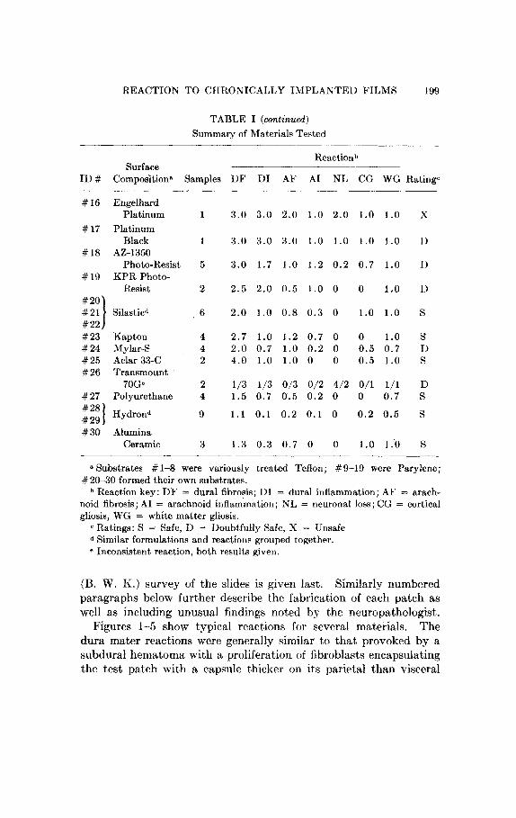
3.0 3 .0 2 .0 1 .0 2 . 0 1 .0 1.0 X
3.0 3.0 3.0 1 .0 1 .0 1.0 1.0 1)
3.0 1.7 1.0 1 . 2 0 . 2 0 .7 1 .0 1)
2 .5 2 .0 0.5 1.0 0 0 1,0 1)
2 . 0 1.0 0 . 8 0 . 3 0 1.0 1 .0 S
2 .7 1.0 1.2 0 .7 0 0 1.0 S 2.0 0.7 1.0 0 . 2 0 0.5 0 .7 I> 4.0 1.0 1.0 0 0 0.5 1.0 8
173 1/3 0/3 012 4/2 0/1 1/1 D 1.5 0 . 7 0.5 0 . 2 0 0 0.7 S
1 . 1 0 .1 0 . 2 0 .1 0 0 . 2 0.5 S
1.3 0 . 3 0 .7 0 0 1.0 1 .0 S
* Substrates # 1-8 were variously treated Teflon; #9-19 were Parylene; # 20-30 formed their own substrates.
Reaction key: D F = dural fibrosis; DI = dural inflammation; AF = arach- noid fibrosis; A1 = arachnoid inflammation; NL = rieuronal loss; CG = cortical gliosis, WG = white matter gliosis.
Ratings: S = Safe, I) = Doubtfully Safe, X = Unsafe d Similar formulations and reactions grouped together. e Inconsistent reaction, both results given.
(B. W. EL) survey of the slides is given last. Similarly numbered paragraphs below further describe the fabrication of each patch as well as including unusual findings noted by the neuropathologist.
The dura mater reactions were generally similar to that provoked by a subdural hematoma with a proliferation of fibrobIasts encapsulating the test patch with a capsule thiclier on its parietal than visceral
Figures 1-5 show typical reactions for several materials.
200 LOEB ET AL.
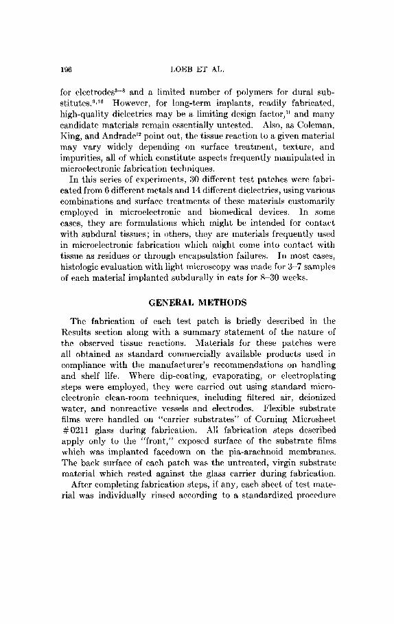
Fig. 1. Photomicrograph 13 weeks after implantation of epoxy on Teflon (test patch #4, “safe”). This section shows marked thickening of both visceral and parietal capsular walls with mild inflammatory reaction (+ +). The reac- tion was apparently secondary to compression, as other implants and other areas of this implant showed much less reaction. Hematoxylin and eosin (30X).
surface. The dural membrane always formed a t least a thin layer between the visceral surface of the test patch and the pia-arachnoid membrane. Thus, the dural reaction is often a significant factor, and the overall assessment takes into consideration the ability of the dura to form a stable, protective layer between the implant and underlying cortex.

REACTION TO CHRONICALLY IMPLANTED FILMS 201
Fig. 2. Photomicrograph 13 weeks after implantation of evaporated titanium on Teflon (patch # 7, “safe”) showing encapsulation with mild lymphocytic reaction ( +) . Hematoxylin and eosin (120 X ) .
Fig. 3. Photomicrograph 13 weeks after implantation of evaporated platinum on Parylene (patch # 15, “safe”) showing encapsulation with mild lymphocytic reaction (+). Hematoxyliri and eosin (120 X).
202 LOEB ET AL.
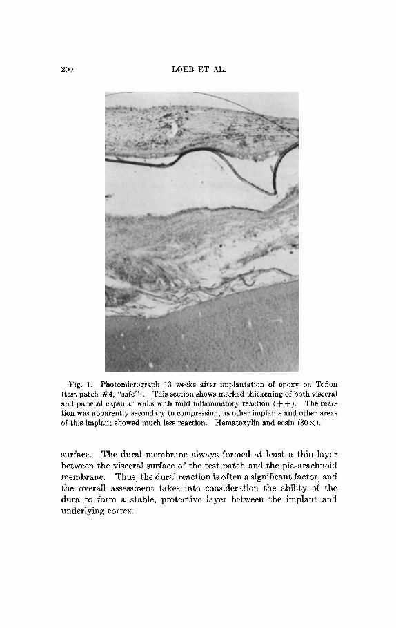
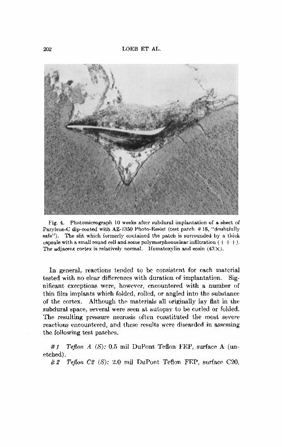
Fig. 4. Photomicrograph 10 weeks after subdural implantation of a sheet of Parylene-C dip-coated with AZ-1350 Photo-Resist (test patch # 18, “doubtfully safe”). The slit which formerly contained the patch is surrounded by B thick capsuIe with a small round cell and some polymorphonuclear infiltration ( + + +). The adjacent cortex is relatively normal. Hematoxylin and eosin (43 X).
In general, reactions tended to be consistent for each material tested with no clear differences with duration of implantation. Sig- nificant exceptions were, however, encountered with a number of thin film implants which folded, rolled, or angIed into the substance of the cortex. Although the materials all originally lay flat in the subduraI space, several were seen at autopsy to be curled or folded. The resuIting pressure necrosis often constituted the most severe reactions encountered, and these results were discarded in assessing the following test patches.
#1 etched).
# a
Teflon A (8): 0.5 mil DuPont Teflon FEF, surface A (un-
TejZon CS (8): 2.0 mil DuPont Teflon FEP, surface C20,

IIEACTION TO CHRONICALLY IMPLANTED FILMS 203
Fig. 5. Photomicrograph 14 weeks after implantation of Silastic sponge Hema- (patch #22, “safe”) showing amchnoidal thickening and fibrosis (4- +).
toxylin and eosiri (120X).
surface etched on both sides by DuPont’s proprietary ion bombard- ment process to make a wettable, bondable surface.
Chemgrip Teflon ( X ) : Patch # 1 surface etched in commercial sodium naphthalene preparation (Chemgrip, Epoxy Technology, Wayne, N.J.) and washed in butanol as recommended by the manu- facturer. The tissue reaction was described as a marked encapsula- tion with granulations.
# 4 h’poxy on Teflon (8): Patch # 3 further fabricated by dip- coating a thin layer of two-component, aminr-cured transparent epoxy (Epotek #301, Epoxy Technology) and curing in a hot air oven a t 65°C for 1 hr (see Fig. 1).
# 5 Epoxylite on Teflon (8): Patch # 3 further fabricated by dip-coating a thin layer of epoxy varnish (Epoxylite 6001-M, Epoxylite Corp., Columbus, Ohio) and baking in a hot air oven a t 65°C for 1 hr. This is a xylol-dissolved, acid-cured bisphenolate rcsin frequently used to dip-coat insulate tungsten micro electrode^.^^
Isonel on Teflon ( D ) : Patch # 3 further fabricated by dip- coating a thin layer of varnish (Isonel 31, Schcnrctady Varnish Co., Schenectady, N.Y.) and baking in a hot air oven a t 65°C for 1 hr.
# S
#6

204 LOEB ET AL.
This is a tough, heat-resistant, flexible varnish coating frequently used on tungsten microelectrodes.14
Titanium on TefEon ( S ) : 1 mil substrate of Teflon FEP surface C (ion bombardment etched on fabricated surface only), vacuum-metallized by vapor-depositing 700 b titanium metal from alumina ceramic-coated molybdenum boat source in liquid nitrogen trapped, oil diffusion pumped vacuum system. Titanium can be used as an undercoat to provide adhesion between evaporated gold films and plastic substrates (see Fig. 2).
Gold or), TefEon (S ) : Patch # 7 further fabricated by vapor- depositing 2000 8 gold metal from a tungsten filament source during the same pump-down as the titanium metallization.
Parylene (D): Approximately 0.7 mil thick vapor-condensed film of Parylene-C deposited on temporary glass carrier substrates in a proprietary process a t Union Carbide Co., Bound Brook, N.J., peeled off carrier substrate to make patches. This is a unique spontaneously polymerizing plastic film which conformally coats complex objects a t room tcmperature under vacuum and has low water vapor transmission and high chemical resistance to degrada- t i ~ n . ' ~ J ~
# 10 Stainless Steel on Parylene ( S ) : Patch # 9 further fabricated by sputtering 1000 b of stainless steel from a #304 alloy target in nitrogen atmosphere. Sevcre loss of adhesion of metal film to sub- strate noted a t autopsy.
# 11 Chromiunz on Parylene (S): Patch # 9 further fabricated by vacuum deposition of 1000 b chromium metal from tungsten basket source. Chromium is a frequently used thin-film electrical resistor element and undercoating to promote adhesion of gold films.
# 12 Sickel on Paryleiie (S ) : Patch # 9 vacuum-metallized with 700 b titanium followed by 2000 b gold. The composite is thcn electroplated with 5 p of nickel from a nickel sulfamate bath (Harstan Chemical Corp., Brooklyn, N.Y.) a t 40°C at 30 ASF (amps/ft*) against a nickel anode.
(:old Electroplate on Payylene (S): Same metallization layer as in #12, electroplated with 24 k t gold 1 p thick instead of nickel, from a cyanide-based bath with gold anodc (Orotemp 24 kt, Technic, Inc., Cranston, 11.1.).
Platanem on Parylene ( S ) : Same metallization 1ayc.r as in #12, electroplated with 1 p thick laycr of bright platinum from an
# 7
# 8
# 9
# 13
# 14
REACTION TO CHRONICALLY IMPLANTED FILMS 20.5
acid bath (Platanex 111, Selrex Corp., Nutley, N.J.) a t 80°C at 10 ASF against a platinum anode.
Evaporated Platinum on Parylene (S): Same metallization layer as in # l a , further vacuum metallized with approx. 1000 A platinum from tungsten filaments electroplated with the Platanex bath described in # 14 (see Fig. 3).
#16 Alkaline Platinum on Parylene ( X ) : Patch #15 further fabricated by electroplating a 1 thick layer of bright platinum from an alkaline bath (Engelhard Industries) a t 85°C a t 10 ASF against a platinum anode.
Platinum Black on Parylene ( D ) : Patch # 15 further fabri- cated by electroplating a 5 p thick layer of platinum black from a 1% chloroplatinic acid solution a t 10 ASF against a platinum anode.
#18 Baked Photo-Resist on Parylene ( D ) : Patch #9 dip-coated with 3-5 p of AZ-1350 positive-working photo-resist (Shipley Co., Newton, Mass.), and baked on a hot plate in air at 375°F for 5 min without light exposure or chemical developing. This is a photo- lithographically formable insulation coating which in very thin, high-resolution coatings is a low-grade but stable elcctrical insulation which acts as a nontoxic substrate for tissue culture of heart muscle and nerves.” In this study, marked leukocytic infiltration was noted in the dural capsule adjacent to the implant (see Fig. 4).
#19 K P R on Parylene (D) : Patch #9 dip-coated with KPR negative-working photo-resist (Iiodak) , stabilized by exposure to high-intensity white light. This is a standard photo-resist used in manufacturing high-resolution microcircuits.
#SO, #21, #22 Silastic ( S ) : Various samples of Silastic 372 Elastomer sheet and fine spongc’ (Dow Corning) which reacted quite uniformly (see Fig. 5 ) .
# 15
#I?’
#2S Kapton (S ) : 0.5 mil Kapton polyimide film (DuPont). #24 Mylar ( D ) : 0.25 mil thick Alylar Type S polyester film
(Dul’ont) . Dural reaction devcribcd as moderately granuloma- tous.
#25 Aclar (S): 1.0 mil thick Aclar 33-C fluorohalocarbon heat- sealable film (Allied Chemical Corp.).
#S6 Transniount ( D ) : 2 mil thick heat setting thermoplastic adhesive (Transmount 70G, USRl Corp., Rutherford, N. J.). Since results in thc two patchrs tested were quite different, both sets of ratings arc given. Both reactions were, however, moderately severe.
206 LOEB ET AL.
#27 Polyurethane (8): Approximately 5 mil thick film of poly- urethane precipitated from a dimethylformamide solution, supplied courtesy of the University of Utah Division of Artificial Organs.
# 28, # 29 Hydron (8): Various pieces of poly(glyco1 methacrylate) gel sponge, supplied courtesy of the University of Utah Division of Artificial Organs.
#SO Alumina (8): 5 mil thick chips of alumina ceramic used for hermetically sealed microcircuit packages.
Reactions were quite uniformly benign.
DISCUSSION
These experiments were intended to serve as an initial screening for a large number of materials formulations of interest to researchers considering the construction of implantable microelectronic devices. It would bc difficult to draw firm, general conclusions from these data, since the number of samples of each material was quite limited and the details of fabrication were often arbitrarily selected to be simply representative of typical microelectronics techniques. How- ever, a number of results were both unexpectcd and consistent enough to bear some prcliminary hypothesizing. It should be emphasized that the designation “probably safe” is based on the overall pattern of the tissue reaction, individual components of which might make a “safe” material quite unsuitable in a given application (e.g., severe dural fibrosis without inflammation seen in # 25) .
There appears to be a significant histopathologic difference between Teflon FEP surfaces etched by ion bombardment ( # 2 ) and sodium naphthalene ( # 3 ) . Since the former process is performed on the plastic film at the factory and the latter conveniently employed in the laboratory for selective area etching, the apparent tendency of the laboratory proccss to leave a toxic surface residue despite the recommended washing procrdurr is unfortunate. Further attempts to improve the washing procedure for biomedical applications would seem justified in view of thc usefulness of the etching procedure. Interrstingly, both the Epoxylite varnish ( # 5) and Epoxy encap- sulant ( # 4), which werr coated on sodium-etched Teflon, formed nontoxic barriers which prevented toxic materials from escaping and causing any significant tissur reaction.
The reactivity of barr I’arylene-C films was a t first surprising in view of its successful use in endothelial tissue culture^,'^ and our own
REACTION TO CHRONICALLY IMPLANTED FILMS 207
extensive experience with Parylene-C as a substrate for microcircuits implanted in the brain.20 Furthermore, metal thin films using Parylene-C as a substrate were quite unreactive (#lo-15), even when the metal film lost adhesion in vivo ( # lo), exposing the under- lying Parylene. Subsequent discussions with persons familiar with the deposition process indicate that small temperature fluctuations during the pyroIysis step, which converts the dimer raw material to an activated divalent radical prior to condensation and polymeriza- tion, can cause inclusion of hydrochloric acid and other breakdown products within the normally homogeneous polymer film. We theorize that this may have happened to the Parylene batch we tested, and that these relatively volatile contaminants either out- gassed or were passivated during the pump-down, substrate heating, and metallization steps employed in patches # 10-15.
The relative reactivity of Mylar film was surprising since it is virtually the same chemical formulation as that of Dacron fiber, a commonly used material in vascular prostheses and as a core to strengthen Silastic dural substitutes.'O As others have pointed out.21 the frequently proprietary fabrication steps whereby raw chemicals are transformed into their final physical form may be critical to the biocompatibiIity of the finished product.
Two industrial-grade materials ( # 18, baked photo-resist; # 26, Transmount) eliciting moderately severe reactions here were tested because of the surprisingIy low toxicity previously noted in tissue culture (unpublished, G. E. L.). These results support the con- tention of others that tissue culture, while usually sensitive, can completely miss certain kinds of foreign-body reactions (e.g., anti- genic, thrombotic, mechanical, etc.) .I2
The rather impressive lack or reaction to alumina ceramic ( # 30) is encouraging since such ceramic materials are generally considered essential to long-term hermetic sealing of electronic circuits destined for immersion in salt water.
Chromium ( # 1 1 ) and nickel (#12) have both been thought to be relatively toxic implants based on expcrience in rabbit muscle,22 although they are frequent constituents of nontoxic steel alloys. In this series, exposed bright evaporated chromium films elicited minimal reactions, while the somewhat grainier electroplated nickel was only moderately reactive. While nrither material is likely to be used directly in contact with tissues, they would be difficult to

208 LOEB ET AL.
replace as undercoatings and internal conductors in microelectronic devices. Their relatively low toxicity here would indicate that they would cause little damage if passively exposed through encapsulant failure, although such failure in the presence of electric currents might release considerably more ions and thus result in much greater toxicity.
The markedly diff erent results obtained with different platinum formulations ( # 14-17) should serve as a warning despite the unfor- tunately small numbers of patches tested in this study. Platinum is frequently mentioned as an ideal material for electrode surfaces designed to be in direct contact with tissues because of its extreme corrosion resistance and nonpolarizing ~ u r f a c e . ~ ~ ~ ~ ~ As expected, evaporated platinum was least reactive, although this particular method of evaporation from tungsten filaments probably produces a significant alloying of the platinum film with tungsten metal which, by itself, is quite reactive in brain.2 The Platancx 111 bright platinum electroplate was also minimally reactive and would appear to be an acceptable way to build up thick films of inert metal on more easily photolithographically fabricated thin films. The severe reaction elicited by the Engelhard alkaline-bath platinum would seem to indicate significant inclusions of toxic materials in the other- wise bright, smooth electroplated surface. The severe reaction to platinum black is surprising since the only potentially toxic species in the chloroplatinic acid bath is platinum ions. Platinum black coatings are frcquently applied to small surface area biomedical electrodes because the very rough surface so generated has a high real surface area and lowers the junction i r n p e d a n ~ e . ~ ~ It may be that this rough surface and/or the possible inclusion and gradual leaching of platinum salts is, in fact, a significant central nervous system irritant when applied over large areas.
The nonspecific observation of severe damage from pressure necrosis under thin films that became rolled and folded has been seen by others.26 Very thin, flexible printed circuits can be readily manu- factured, and their ability to conform to the convoluted cortical surface and move freely with the brain during motion in the skull would seem desirable. However, we are quite certain that most, if not all, of the rolling and folding of the very thin flexible films im- planted in the study occurred gradually after implantation. Among the mechanisms which might be hypothesized are differentially

REACTION TO CHRONICALLY IMPLANTED FILMS 209
contracting dural and arachnoid adhesions, simple relative transverse rubbing motion between dura and pia-arachnoid, and gradual curling of the implant itself as a result of differential adsorption and absorp- tion of water, lipids, and protein on various parts of the surface. In each of these mechanisms, the flaccidity of the thin film would actually contribute to the tendency of an implant to cause pressure necrosis rather than avoid it. I n the overall design of any such thin film subduraI implant, attention will have to be given to pro- viding some form of anchoring or st,ructural support at the perimeters to prevent this complication.
This work was supported by National Iristitotes of Health Contract The authors wish to express their appreeiat.ion t.o Dr. F, T. #NIH-i0-2277.
Hambrecht for his comment,s and suggestions.
References 1. F. T. Hambrecht and K. Frank, in Advances i n Electronics and Electron
Physics, vol. 38, L. Martorl, Ed., Academic Press, New York, 1975. 2. L. L. Hench arid E. C. Ethridge, Advan. Biomed. Eng., 5, 35 (1975). 3. N. C. Delarue, E. A. Linell, and K. G. McKenzie, J . Neurosurg., 1, 239
(1944). 4. J. C. Collias and E. 33. Mttrtuelidis, J . Neurosury., 14, 302 (1957). 5. F. It. Robinson and M. T. Johnson, “Histopathological studies of tissue
reactions to various metals implanted in cat brains,” AS]) Technical Report #61-397, U S . Air Force, 1961.
6. R. Cooper and H. J. Crow, Med. Bid. Eng., 4, 575 (1966). 7. M. C. Wetzel, L. G. Howell, arid K. J . Bearie, J . Neurosurg., 31, 658 (1969). 8. A. M. Uymond, L. E. Kaechele, J. M. Jurist, and P. H. Crandall, J . Neuro-
surg., 33, 574 (1970). 9. P. Terig arid C. Popatheodorov, J . Keiirol., N e i i r o s i q . , Psychiat., 26, 244
(1963). 10. J. F. Lee, C ; . L. Odom, arid G. T. Tilidall, J . h’eurosurg., 27, 558 (1967). 11. P. E. K. I)onaldson, Proc. I E E E , Control and Science, 120, 281 (1973). 12. 1). L. Coleman, 1:. N. King, and J. 11. Andrade, J . Riomed. Mater. Res.,
8, 199 (1974). 13. J. A. Freeman, E E G Clin. Keuropliysiol., 26, 623 (196‘3). 14. E. Marg, Natuue, 202. 601 (1964). 15. H. Lee, I). Stoffey, and K. IVeville, h‘ew /,inear Polymers, McGraw-Hill,
New York, 1967, pp. 83-100. 16. C;. E. Loeb, >I. Bak, &I. Salcmari, and E. Schmidt, Z E E E - B M E , in press. 17. C. A. Thomas, Jr., P. A. Springer, G . E. Loeb, Y. Berwald-Netter, and L. M.
Okun, Exp. Cell Res., 74, 61 (1972). 18. M. Barvic, K. Klimerit, arid M. Zavedil, J . Rioi~ed . Mafer . Res., 1,313 (1967).

210 LOEB E T AL.
19. R. H. Kahn, “Multiple layered intimal linings by perfusion culture.” Nat. Tech. Annual Report, NHLI Grant #NIH-71-2054, 1972 and 1973.
Info. Service Accession # PB-207088, # PB-223039. 20. G. E. Loeb, W. B. Marks, and P. Beatty, Med. Ba’ol. Eng., in press. 21. J. Autian, J . Biomed. Mater. Res., 1, 433 (1967). 22. P. G. Laing, A. B. Ferguson, and E. S. Hodge, J. Biomed. Muter. Res., 1,
135 (1967). 23. E. Warburg, Ann. Phys., 6, 125 (1901). 24. H. P. Schwan, Ann. New York Acud. Sci., 148, 191 (1968). 25. R. C. Gesteland, B. Howlarid, J. Y . Lettvin, and A. H. Pitts, Proc. Z.R.E.,
47, 1856 (1959). 26. R. H. Pudenz, L. A. Bullara, and A. Talalla, Surg. Neural., 4,37 (1975).
Received November 18, 1975 Revised March 12, 1976