hirdls - earth observing system · the purpose of this document is to describe the algorithmic...
TRANSCRIPT

SW-HIR-168
HIRDLSHigh Resolution Dynamics Limb Sounder
ALGORITHM THEORETICAL BASIS DOCUMENT
ATBD-HIR-01
Calibration and Geo-location of HIRDLS radiances
4th October 1999
See http://www.atm.ox.ac.uk/user/wells/atbd.html for latest version
Any comments on this document may be addressed to [email protected]
CHANGE HISTORY15-Jan-1999 Original Version. Submitted to ATBD Review Panel chaired by Larry Gordley
(GSFC 18-May-1999).
06-Jul-1999 Corrected typos. Changed "boresight" to "principal optical axis". Used "chopperperiod" instead of "chopper frequency". Removed references to accelerometers. Removed eBB
from expression for calibrated radiance in Section 3.8. Incorporated changes to Level 1 filedescription agreed at L1 Science Software Review meeting (Oxford 01-Jul-1999).
12-Jul-1999 Changed latitude, longitude and time items in Level 1 file contents description to"standard" HDF-EOS names and types. Added rad_flag description.
13-Jul-1999 Added Spacecraft velocity (ECI mm/s) to Level 1 file contents
27-Aug-1999 Revised Level 1 file contents description to use HDF structure names and to addView Direction item. Added draft Appendix 5.2.
10-Sep-1999 Revised some HDF structure names and modified Appendix 5.2.
23-Sep-1999 Edits to 5.2.1 and change cold filter temperature from LNS2TMP to FPA_TEMP
4-Oct-1999 Added Recommendation 3 response to Appendix 5.2. Submitted to PSO as requestedin e-mail from Jim Closs dated 23 July 1999.
CONTENTS
1. Introduction
• 1.1 Purpose and Scope
2. Overview and Background Information
• 2.1 HIRDLS Experiment Description
• 2.2 Data Processing Environment
• 2.3 Algorithm Heritage
• 2.4 Lessons Learned from ISAMS
3. Calibration Algorithms
• 3.1 Raw Data Quality Control
• 3.2 Engineering Telemetry Conversion
• 3.3 Spacecraft Location
• 3.4 Spacecraft Attitude
• 3.5 Instrument Pointing
• 3.6 Tangent Point Location
• 3.7 Celestial Bodies in Field of View
• 3.8 Radiometric Calibration
• 3.9 Error Estimation
4. Processing Considerations
• 4.1 Data Volumes
• 4.2 Numerical Computation Considerations
• 4.3 Data Flow
• 4.4 File Formats
• 4.5 Quality Control and Diagnostics
• 4.6 Exception Handling
• 4.7 Coding Standards
5. Appendices
• 5.1 Applicable Documents
• 5.2 CHEM-1/SOLSTICE ATBD Review, May 18-19, 1999.

• 5.3 Acronyms and Abbreviations
1. INTRODUCTION
1.1 PURPOSE and SCOPE
The requirement for this document is a CDRL (No 601) for HIRDLS specified in GSFC 424-28-21-03 and due for review 48 months before launch. In a letter from Michael King to PIs dated 6May, 1998 delivery to EOS Project Science Office on 15 Jan 1999 was requested.
The purpose of this document is to describe the algorithmic basis for the software to be used toconvert HIRDLS Level 0 data (raw counts of the spacecraft telemetry) to Level 1 data. In Level1 data, radiances and engineering data are calibrated and expressed in conventional units. Inaddition, information about the location of observations is derived from ephemerides andinstrument pointing data. This document is restricted to the discussion of algorithms used in theproduction of standard HIRDLS products and does not address the use of research andcalibration data obtained in special observation modes (e.g. spacecraft pitch-down, moon-viewing).
2. OVERVIEW and BACKGROUND INFORMATION
HIRDLS is an experiment to be flown on the EOS-CHEM satellite as a part of the NASA EOSprogram and is collaborative effort between Oxford University in the UK (PI J.J. Barnett) and
the University of Colorado in Boulder, USA (PI J.C. Gille). The science goals of HIRDLS are toobserve the global distributions of temperature and several trace species in the stratosphere and
upper troposphere at high vertical and horizontal resolution.
Further details can be found in Gille, J. C. and J. J. Barnett: Conceptual Design of the HighResolution Dynamics Limb Sounder (HIRDLS) for the EOS Chemistry Mission.
The instrument will obtain profiles over the entire globe, including the poles, both day and night.Complete Earth coverage (including polar night) can be obtained in 12 hours. High horizontalresolution is obtained with a commandable azimuth scan which, in conjunction with a rapidelevation scan, typically provides a 2,000 to 3,000 km-wide swath of profiles along the satellitetrack. Vertical profiles are spaced every 4 degrees in latitude and 5 degrees in longitude, with 1to 1.5 km vertical resolution.
2.1 HIRDLS EXPERIMENT DESCRIPTION
HIRDLS is an infrared limb-scanning radiometer designed to sound the upper troposphere,stratosphere, and mesosphere to determine temperature; the concentrations of O3, H2O, CH4,N2O, NO2, HNO3, N2O5, ClONO2, CFC11, CFC12, and aerosols; and the locations of polarstratospheric clouds and cloud tops. The goals are to provide sounding observations with

horizontal and vertical resolution superior to that previously obtained; to observe the lowerstratosphere with improved sensitivity and accuracy; and to improve understanding ofatmospheric processes through data analysis, diagnostics, and use of two- and three-dimensionalmodels.
The optical system with a telescope consisting of a plane scan mirror, a parabolic primary andellipsoidal secondary mirror, is shown schematically in Figure 1.
Figure 1.
Other components critical to the radiometric calibration discussed in this document are thechopper, the space reference relay mirror and the in-flight calibrator mirror. The scan mirrorrotates about both azimuth and elevation axes. High-precision pointing information is obtainedby the use of gyroscopes mounted on the instrument optical bench to measure changes inalignment in space of the primary optical axis.
The chopper wheel has six gaps and rotates at a nominal commandable frequency of 83.3Hz.This produces a nominal 500Hz cycle in the detector signal waveform. In normal operation, allHIRDLS telemetry timing is based on the sync pulse generated once per revolution by thechopper. The primary telemetry sample rate is once per chopper revolution (c. 12ms). A sciencedata packet is generated every eight chopper revolutions (a minor frame) i.e. c. 96ms. A majorframe consists of 8 minor frames, 64 chopper revolutions, and lasts approximately 768ms. Alltelemetry points (listed in section 3.2) are sampled at least once during a major frame. This isalso the interval allowed for all the SAIL tasks (mentioned later and described in SAIL SoftwareRequirement Document SW-HIR-147A) to complete an operation cycle.

HIRDLS performs limb scans in the vertical at multiple azimuth angles, measuring infraredemissions in 21 channels ranging from 6.12 to 17.76 micron. Each channel uses two separateband pass interference filters and a photoconductive HgCdTe detector cooled by Stirling cycledevice. Details of the detector layout can be seen in the field of view map, Figure 2.
Figure 2.
Four channels measure the emission by CO2. Taking advantage of the known mixing ratio ofCO2, the transmittance is calculated, and the equation of radiative transfer is inverted todetermine the vertical distribution of the Planck black body function, from which thetemperature is derived as a function of pressure. Once the temperature profile has beenestablished, it is used to determine the Planck function profile for the trace gas channels. Themeasured radiance and the Planck function profile are then used to determine the transmittanceof each trace species and its mixing ratio distribution.
Winds and potential vorticity are determined from spatial variations of the height of geopotentialsurfaces. These are determined at upper levels by integrating the temperature profiles verticallyfrom a known reference base. HIRDLS will improve knowledge of data-sparse regions bymeasuring the height variations of the reference surface provided by conventional sources withthe aid of a gyro package. This level (near the base of the stratosphere) can also be integrateddownward using nadir temperature soundings to improve tropospheric analyses.
HIRDLS raw instrument data rate is approximately 60 kbps.

The instrument is controlled in routine operations by Science Algorithm ImplementationLanguage (SAIL) programs running in the Instrument Processor Unit (IPU). These programsgenerate observation sequences which are used to control the scan mirror and instrumentpointing. In addition the programs also monitor instrument health and safety and control suchthings as the operation of the sunshield door. However these functions are not within the scopeof this document.
The Scan Pattern shown below will be used as the basis for the design of the Scanner controlhardware and software. It is representative of all scan patterns in the azimuth direction. In theelevation direction it is representative of an operational scan profile with respect to peak-to-peakamplitude and average offset. The ultimate operational offset may be larger or smaller,depending on the ephemerides achieved after launch. A more comprehensive set of profiles, andthe way in which they have been derived, will be found in SP-HIR-198.
Figure 3.
Figure 3 shows scan mirror elevation angles (expressed in terms of boresight altitudes) plottedagainst azimuth angles in a full scan sequence which takes approximately 65 seconds tocomplete. The coordinates for points on the sequence A, B, C ... AE are given in the followingtable.
Elevation shaft Azimuth Time Tangent point angle (deg) shaft angle height Low Nominal High (deg) (s) (km)A TBD TBD TBD TBD 0.00 N/A Start at IFC view
B -1.64 -1.11 -0.53 10.25 1.87 137.0 Azimuth scan at spaceC -1.62 -1.10 -0.52 4.02 2.16 137.0 view elevationD -1.61 -1.09 -0.52 -2.21 2.44 137.0E -1.63 -1.11 -0.53 -8.44 2.79 137.0F -1.67 -1.13 -0.54 -14.67 3.23 137.0
G -1.72 -1.17 -0.56 -20.90 4.31 137.0 Elevation scan 1 (down)

H -1.37 -0.83 -0.23 -20.90 5.31 105.4I -1.34 -0.80 -0.20 -20.90 5.41 103.0J 0.03 0.53 1.09 -20.90 13.15 -27.0
K 0.03 0.51 1.05 -14.67 14.15 -27.0 Elevation scan 2 (up)L -1.30 -0.77 -0.20 -14.67 21.89 103.0M -1.32 -0.80 -0.22 -14.67 21.99 105.4N -1.67 -1.13 -0.54 -14.67 23.00 137.0
O -1.63 -1.11 -0.53 -8.44 23.99 137.0 Elevation scan 3 (down)P -1.29 -0.78 -0.21 -8.44 24.99 105.4Q -1.27 -0.76 -0.19 -8.44 25.09 103.0R 0.03 0.50 1.03 -8.44 32.83 -27.0
S 0.03 0.50 1.01 -2.21 33.83 -27.0 Elevation scan 4 (up)T -1.25 -0.75 -0.19 -2.21 41.57 103.0U -1.28 -0.77 -0.21 -2.21 41.67 105.4V -1.61 -1.09 -0.52 -2.21 42.67 137.0
W -1.62 -1.10 -0.52 4.02 43.67 137.0 Elevation scan 5 (down)X -1.28 -0.77 -0.21 4.02 44.67 105.4Y -1.26 -0.75 -0.19 4.02 44.77 103.0Z 0.03 0.50 1.02 4.02 52.51 -27.0
AA 0.03 0.50 1.03 10.25 53.51 -27.0 Elevation scan 6 (up)AB -1.27 -0.76 -0.19 10.25 61.24 103.0AC -1.30 -0.78 -0.22 10.25 61.34 105.4AD -1.64 -1.11 -0.53 10.25 62.34 137.0
AE TBD TBD TBD TBD 64.78 N/A Dwell at IFC viewA TBD TBD TBD TBD 65.28 N/A
Notes:
1. This table is based on the sequences shown in tables 4, 5 and 6 of SP-HIR-198, with thetiming taken from table 5.
2. The sections of each elevation scan between -27 and +103 km and between +105.4 and+137 km should be scanned at constant elevation shaft angle rates. The short sectionbetween 103 and 105 km is provided to enable the rate to change.
3. The tangent point height is given for the boresight.
4. The elevation and azimuth shaft angles for the IFC view are intentionally not specifiedhere.
5. Line-of-sight angles are approximately double the shaft angles.
6. This table is intended as an example of how the scanner may be required to operate in thebaseline mode. It is for example possible that the sequence may be required in the reverseorder, or that a greater number of separate constant rate segments may be required withineach elevation scan.

Figure 4.
Figure 4 (which assumes a spherical earth and circular satellite orbit and ignores the effects ofazimuth scanning) shows the main features of the changes in (Channel 5) tangent point location.Axes are labelled in kilometers. HIRDLS views to the rear of the spacecraft. As the instrumentlooks higher in the atmosphere so the tangent point approaches the spacecraft. The lowesttangent points (2 and 3) are approximately 3080km from the spacecraft, the highest tangentpoints (1 and 4) are approximately 2715km from the spacecraft, a difference of 365km. During asingle 'vertical' scan (1 to 2, or 3 to 4) the spacecraft moves approximately 65km so thehorizontal span of a profile is approximately 300km for a down scan or 430km for an up scan.The span of the full scan profile of Figure 3 is also illustrated.
2.2 DATA PROCESSING ENVIRONMENT
Algorithms for processing HIRDLS instrument data are developed by the PI team and deliveredto NASA as Science Data Product (SDP) Software for installation in an EOSDIS data processingfacility. The SDP software resulting from this document will be designed, coded and tested onthe Oxford University Science Computing Facility (SCF). The software will then be transferredto the HIRDLS team at UCB who are responsible for the integration of all HIRDLS productionprocessing software into EOSDIS.
2.3 ALGORITHM HERITAGE
The HIRDLS instrument has a very long heritage from several instruments flown on theNIMBUS and Upper Atmosphere Research Satellite (UARS) spacecraft The most recent andrelevant experience was with the Improved Stratospheric and Mesospheric Sounder (ISAMS)instrument on UARS which involved most of the main features of HIRDLS except for theinstrument gyroscopes. Algorithms for processing ISAMS data were coded and delivered toNASA for use in routine product generation in a very similar way to that planned for the EOSprogramme. The approach used for in-flight radiometric calibration and a discussion of theresults was published byC.D. Rodgers et al in the Journal of Geophysical Research, 101, 9775-9794, 1996.
2.4 LESSONS LEARNED FROM ISAMS
The main problem that the ISAMS algorithms needed to address was the large orbital change inthermal environment of a satellite radiometer (typically two spacecraft terminator crossing perorbit). Almost all the engineering telemetry showed a large orbital signature even in cases where
components were tightly thermostated. As these signatures tended to be in phase it was verydifficult to determine the partial derivatives (dependencies) precisely. For example, a telemetrypoint could vary with supply voltage and temperature but the voltage and temperature couldthemselves exhibit very similar variations. Most dependencies were better determined by specialtests when components were perturbed from their normal operational conditions than by any sortof regression technique on operational data. Generally the instrument was better operatedasynchronously with orbit so that orbital effects were more easily identified. Some ISAMSchannels had about 22 radiometric calibration sequences per orbit which was adequate (whendoing HIRDLS-like single-sided viewing) but the 6 calibration sequences used for somechannels were not frequent enough to follow the observed variations in offset and gain during anorbit.
The optimal estimation techniques used to process Level 1 radiances to Level 2 (geophysicalparameters such as temperature and volume mixing ratios) needed not only accurate radiancevalues but also reliable estimates of the radiance error terms in the "measurement error vector".On the ISAMS experiment it was found that the best error estimates could be derived frommultiple repeated successive observations of the same variable over a short period of time.Simple pairs of adjacent observations were invaluable.
Validation of the radiometric calibration required that the radiometric performance of theinstrument can be well-modelled. This demanded knowledge of the representative temperatureand emissivities of all optical components. Emissivities are extremely difficult to measure in-orbit and only somewhat less so in a calibration facility. Not all the ISAMS mirror temperatureswere telemetered and neither was that of the chopper. Consequently a full validation of theradiometric model was not possible. There was also some evidence that the telemeteredtemperature of the internal calibration target did not represent its effective temperature. This wasprobably because of the inappropriate electronic circuit design which was used for these sensors.Algorithm design should not preclude minor modifications to incorporate improvements andcorrections derived from in-flight experience.
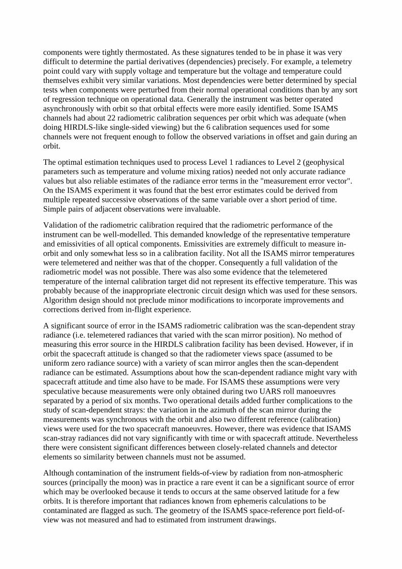
A significant source of error in the ISAMS radiometric calibration was the scan-dependent strayradiance (i.e. telemetered radiances that varied with the scan mirror position). No method ofmeasuring this error source in the HIRDLS calibration facility has been devised. However, if inorbit the spacecraft attitude is changed so that the radiometer views space (assumed to beuniform zero radiance source) with a variety of scan mirror angles then the scan-dependentradiance can be estimated. Assumptions about how the scan-dependent radiance might vary withspacecraft attitude and time also have to be made. For ISAMS these assumptions were veryspeculative because measurements were only obtained during two UARS roll manoeuvresseparated by a period of six months. Two operational details added further complications to thestudy of scan-dependent strays: the variation in the azimuth of the scan mirror during themeasurements was synchronous with the orbit and also two different reference (calibration)views were used for the two spacecraft manoeuvres. However, there was evidence that ISAMSscan-stray radiances did not vary significantly with time or with spacecraft attitude. Neverthelessthere were consistent significant differences between closely-related channels and detectorelements so similarity between channels must not be assumed.
Although contamination of the instrument fields-of-view by radiation from non-atmosphericsources (principally the moon) was in practice a rare event it can be a significant source of errorwhich may be overlooked because it tends to occurs at the same observed latitude for a feworbits. It is therefore important that radiances known from ephemeris calculations to becontaminated are flagged as such. The geometry of the ISAMS space-reference port field-of-view was not measured and had to estimated from instrument drawings.

Considerable effort was expended in the development of ISAMS algorithms to provide resilienceagainst possible energetic particle events (particularly in the South Atlantic Anomaly) affectingthe detector electronics and causing "spikes" in the radiance telemetry. In practice no radiance"spikes" were ever attributed to this cause but the micro-processor random access memorysuffered several (reversible) single-bit corruptions.
Before UARS launch it was anticipated that the limiting factor in the use of ISAMS radianceswould be the detector noise and this concept was implicitly incorporated in some algorithms. Inpractice it was found to be the detector gain (which between detector decontamination sequenceswas extremely closely related to detector temperature) was more of a performance limitationbecause of signal quantisation.
ISAMS production data processing software contained several components intended to providedata for monitoring instrument performance. Although this function is essential it is not clear thatit is best combined with production processing.
It was found that some ISAMS data were unsuitable for production processing (for exampleduring special observing sequences) and there was no easy way of determining this from thetelemetry stream alone. A calibration file indicating the time span of data which should beavoided by production processing would have been better than the ad-hoc approach used.
Some problems in ISAMS processing were caused by calibration of the pressure modulators andmolecular sieves. These components will not be used in HIRDLS. However ISAMS did not havegyroscopes attached to the optical bench nor did it operate over a wide azimuth scan.
3. CALIBRATION ALGORITHMS
3.1 RAW DATA QUALITY CONTROL
All algorithms must be designed to handle unexpected values in the data stream cleanly. Mostcommon failures of this kind are caused by overflows (division by zero) and attempting tocalculate the square root of negative numbers. On detection of such problems algorithms willissue warnings to the PI team and, where possible, flag a section of data as unreliable andcontinue to the next section. In all cases algorithms should terminate in a predictable fashion.
Inevitably some data will be corrupted in transmission from the satellite to the data processingfacility. By judicious choice of protocols most of the errors will be detected and corrected in theLevel 0 product. However, there will remain some data which should be flagged as corruptedand all processing algorithms must check this data quality information (e.g. parity errors,checksum errors, loss of synchronisation, drop-outs etc) to ensure that suspect information is notused in data processing.
Some items in the data stream follow simple patterns that should be checked for consistency.Typically there are counters which are expected to increment in a predictable way. There are afew cooler subsystem items where the mechanism telemetry can be checked against themechanism demand. The action to be taken on detection of an anomaly needs to be determinedon a case-by-case basis but invariably a detailed warning needs to be issued to the PI team.

Many temperatures, particularly those important in radiometric calibration, are measured withmultiple sensors of different types (thermistors and platinum resistance thermometers). Largediscrepancies between measurements which are expected to be similar will be monitored andreported to the PI team. Suspect telemetry values will not be used in calibration.
Some housekeeping telemetry is expected to vary smoothly (e.g. mirror temperatures) or beeffectively constant (e.g. reference voltages) but may in practice exhibit spikes possibly causedby energetic particles affecting a sensor. Similar effects are also seen when working near thedigitisation limit of an analog to digital convertor. In such cases a spike detection and removalalgorithm is required. Because the data to be de-spiked are not necessarily evenly spaced in time,and because the filter has to be capable of fine tuning, a Kalman filter technique is particularlyappropriate.
3.2 ENGINEERING TELEMETRY CONVERSION
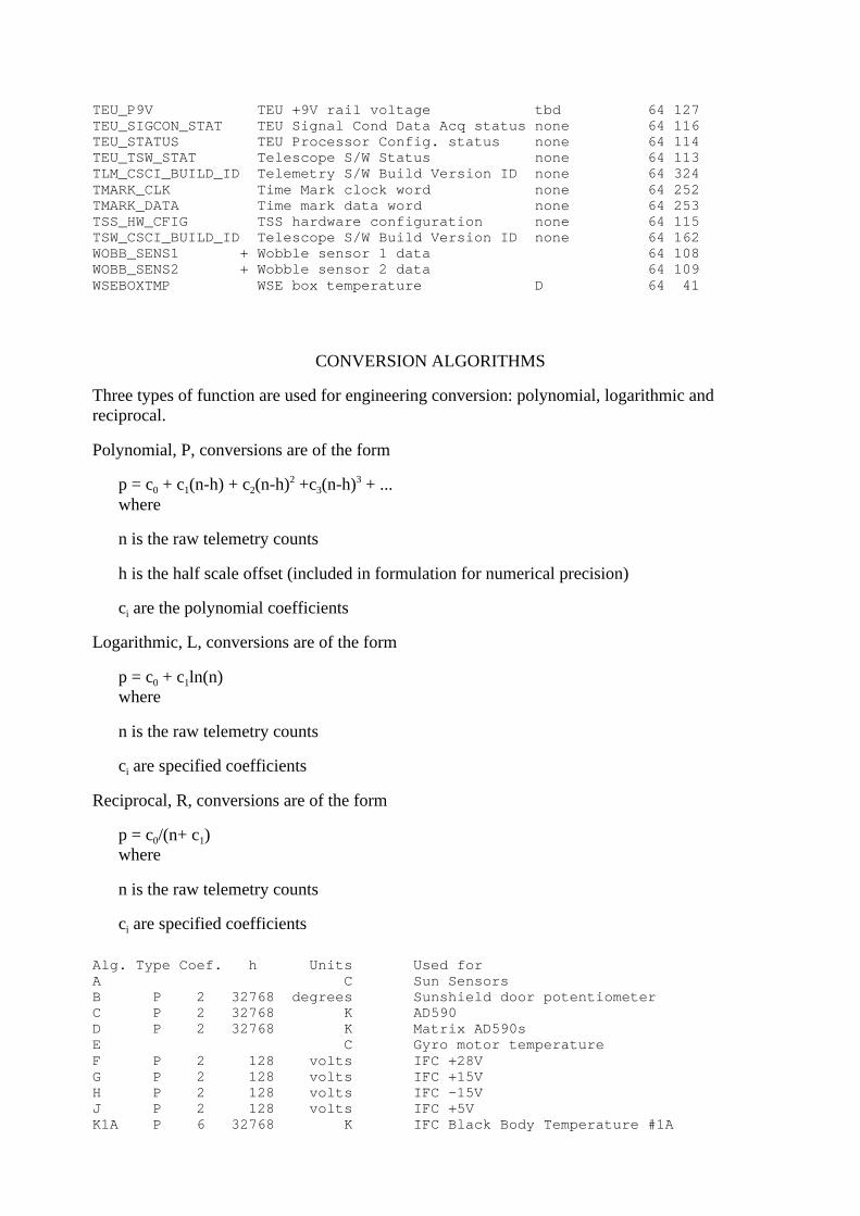
A significant part of the test and calibration phase of HIRDLS will be the validation of theengineering telemetry conversion. Indeed it is planned that some of the same source code usedfor test and calibration will be used in the production data processing. Temperatures which arerequired to high precision (e.g. the IFC Black Body temperatures used in radiometric calibration)will be measured using 500 ohm platinum resistance sensors on a 4-wire AC bridge for whichpolynomial coefficients are provided to convert telemetered values to values on the InternationalTemperature Scale. The following table lists all the data items which will be contained in theHIRDLS Level 0 (instrument telemetry) file and indicates, where appropriate, the algorithm usedto convert each item into engineering units. Items used in the calibration algorithms described inthis document are indicated by '+'.
Chopper revs./MNEMONIC DESCRIPTION ALGORITHM Sample ID
AZIMDAT + Azimuth encoder tbd 1 103AZMOTR_CRRT Azimuth motor current D 8 107AZMOTTMP Azimuth motor temperature D 64 138BEUBOXTMP BEU box temperature D 64 388BEUMNTTMP BEU mount temperature D 64 389CALMIRTMP01 + Cal. Mirror temperature #1 D 64 150CALMIRTMP02 + Cal. Mirror temperature #2 D 64 151CALMIRTMP03 + Cal. Mirror temperature #3 ZC 64 152CCUBOXTMP CCU box temperature D 64 37CHOPHSGTMP01 Chopper housing temperature #1 D 64 147CHOPHSGTMP02 Chopper housing temperature #2 D 64 148CHOPHSGTMP03 Chopper housing temperature #3 ZC 64 149CHOPMOT_CRRT Chopper motor current tbd 64 112CHOP_PERIOD + Chopper period setting ZB 64 387CMD_CSCI_BUILD_ID Command S/W Build Version ID none 64 323COMPHEADTMP Compressor head temperature D 64 44COMP_AMP_ACT Compressor amplitude (actual) N3 64 339COMP_AMP_DMD Compressor amplitude (demand) N3 64 338COOLRADTMP1 Cooler Radiator temperature 1 D 64 42COOLRADTMP2 Cooler Radiator temperature 2 D 64 43CRYOTIP_SETP Cryo tip temperature set point N1 64 331CRYOTIP_TMP_D0 Cryo tip temperature 0 N1 64 332CRYOTIP_TMP_D1 Cryo tip temperature 1 N1 64 333CSS_CSCI_BUILD_ID Cooler F/W Build Version ID none 64 343CSS_CURRENT Cooler total mean current M 64 330CSS_DDCAG_STAT Cooler DDC & caging status none 64 328

CSS_ERROR Cooler error flags none 64 329CSS_FREQ_ACT Cooler frequency (actual) P 64 335CSS_FREQ_DMD Cooler frequency (demand) P 64 334CSS_MSG_NUMBER CSS-IPS data message number none 64 342CSS_OPSTATUS Cooler operating status none 64 327CSS_PH_ACT Comp./Disp. phase (actual) N2 64 337CSS_PH_DMD Comp./Disp. phase demand) N2 64 336DISPL1TMP Displacer 1 body temperature D 64 45DISPL2TMP Displacer 2 body temperature D 64 46DISP_AMP_ACT Displacer amplitude (actual) N3 64 341DISP_AMP_DMD Displacer amplitude (demand) N3 64 340DOOR_POT Door angle sensor B 64 410DOOR_SAF_ANG Door Safe Angle setting B 64 51EEABOXTMP EEA box temperature D 64 40EEAMNTTMP EEA mount temperature D 64 394EEA_STATUS EEA configuration status none 64 104ELEVDATA + Elevation encoder A tbd 1 101ELEVDATB + Elevation encoder B tbd 1 102ELMOT1TMP1 Elevation motor 1 temperature 1 D 64 395ELMOT1TMP2 Elevation motor 1 temperature 2 D 64 396ELMOT2TMP1 Elevation motor 2 temperature 1 D 64 397ELMOT2TMP2 Elevation motor 2 temperature 2 D 64 397ELMOTR1_CRRT Elevation motor 1 current D 8 105ELMOTR2_CRRT Elevation motor 2 current D 8 106FPA_TEMP_A Focal Plane temperature A tbd 64 163FPA_TEMP_B Focal Plane temperature B tbd 64 164FRAMECNT Minor frame count none 8 267GEUBOXTMP GEU box temperature D 64 38GMU_HSG_TMP GMU Housing temperature D 64 161GMU_MNT_TMP GMU Mount temperature D 64 160GYR0_ADAT + Gyro 0 angle data Section 3.5 1 69GYR0_BDTMP + Gyro 0 board temperature tbd 64 65GYR0_CAPL Gyro 0 cap loop output tbd 64 77GYR0_MAGDAT + Gyro 0 magnetometer data Section 3.5 64 73GYR0_MOTC Gyro 0 motor current tbd 64 85GYR0_MOTV Gyro 0 motor volts tbd 64 81GYR0_N15V Gyro 0 -15 volts tbd 64 97GYR0_P15V Gyro 0 +15 volts tbd 64 93GYR0_STAT Gyro 0 status word none 64 89GYR0_TEMP + Gyro 0 temperature E 64 61GYR1_ADAT + Gyro 1 angle data Section 3.5 1 70GYR1_BDTMP + Gyro 1 board temperature tbd 64 66GYR1_CAPL Gyro 1 cap loop output tbd 64 78GYR1_MAGDAT + Gyro 1 magnetometer data Section 3.5 64 74GYR1_MOTC Gyro 1 motor current tbd 64 86GYR1_MOTV Gyro 1 motor volts tbd 64 82GYR1_N15V Gyro 1 -15 volts tbd 64 98GYR1_P15V Gyro 1 +15 volts tbd 64 94GYR1_STAT Gyro 1 status word none 64 90GYR1_TEMP + Gyro 1 temperature E 64 62GYR2_ADAT + Gyro 2 angle data Section 3.5 1 71GYR2_BDTMP + Gyro 2 board temperature tbd 64 67GYR2_CAPL Gyro 2 cap loop output tbd 64 79GYR2_MAGDAT + Gyro 2 magnetometer data Section 3.5 64 75GYR2_MOTC Gyro 2 motor current tbd 64 87GYR2_MOTV Gyro 2 motor volts tbd 64 83GYR2_N15V Gyro 2 -15 volts tbd 64 99GYR2_P15V Gyro 2 +15 volts tbd 64 95GYR2_STAT Gyro 2 status word none 64 91GYR2_TEMP + Gyro 2 temperature E 64 63GYR3_ADAT + Gyro 3 angle data Section 3.5 1 72GYR3_BDTMP + Gyro 3 board temperature tbd 64 68GYR3_CAPL Gyro 3 cap loop output tbd 64 80GYR3_MAGDAT + Gyro 3 magnetometer data Section 3.5 64 76

GYR3_MOTC Gyro 3 motor current tbd 64 88GYR3_MOTV Gyro 3 motor volts tbd 64 84GYR3_N15V Gyro 3 -15 volts tbd 64 100GYR3_P15V Gyro 3 +15 volts tbd 64 96GYR3_STAT Gyro 3 status word none 64 92GYR3_TEMP + Gyro 3 temperature E 64 64HIRCLKLSB HIRDLS clock least sig. byte none 1 251HK_FORMAT_ID Housekeeping format table ID none 8 268IFCBB_FRPL_TMP IFCBB front plate temperature tbd 64 165IFCBB_TMP1 + IFC Black Body temperature #1 K1 64 167IFCBB_TMP2 + IFC Black Body temperature #2 K2 64 168IFCBB_TMP3 + IFC Black Body temperature #3 K3 64 169IFC_OVEN_TMP IFC ref resistor oven temp L 64 166IFC_PSV_N15 IFC -15V rail volts H 64 172IFC_PSV_P15 IFC +15V rail volts G 64 171IFC_PSV_P28 IFC +28V rail volts F 64 170IFC_PSV_P5 IFC +5V rail volts J 64 173IPUBOXTMP IPU box temperature D 64 391IPU_3P3DDC_TMP Wkg IPU +3.3V DDC temperature D 64 304IPU_3P3VOLTS Wkg IPU +3.3V supply volts W 64 300IPU_5VDDC_TMP Wkg IPU +5V DDC temperature D 64 305IPU_5VOLTS Wkg IPU +5V supply volts V 64 301IPU_CSCI_BUILD_ID IPU S/W Build Version ID none 64 325IPU_N15VOLTS Wkg IPU -15V supply volts X2 64 303IPU_P15VOLTS Wkg IPU +15V supply volts X1 64 302LNS1WFTMP01 + Lens 1-WF temperature 1 D 64 141LNS1WFTMP02 + Lens 1-WF temperature 2 D 64 142LNS1WFTMP03 + Lens 1-WF temperature 3 ZC 64 143LNS2TMP01 + Lens 2 temperature 1 D 64 144LNS2TMP02 + Lens 2 temperature 2 D 64 145LNS2TMP03 + Lens 2 temperature 3 ZC 64 146LNSASSY_TMP01 OBA lens assembly temp. #1 D 64 156LNSASSY_TMP02 OBA lens assembly temp. #2 D 64 157M1TMP01 Pri. (M1) mirror temperature 1 D 64 139M1TMP02 Pri. (M1) mirror temperature 2 D 64 140M1TMP03 Pri. (M1) mirror temperature 3 ZC 64 399M2TMP01 Sec. (M2) mirror temperature #1 D 64 153M2TMP02 Sec. (M2) mirror temperature #2 ZC 64 154MACMDS_RCVCT Macro commands: received count none 64 263MACMDS_REJCT Macro cmds: rejected count none 64 264MACMD_LAST_CN Last Macro command: number none 64 266MACMD_LAST_RC Last Macro command: result code none 64 265OBA_PLT_TMP OBA aperture plate temp D 64 159ORB_DAT_00 S/C Ancillary data item #0 tbd 64 21ORB_DAT_01 S/C Ancillary data item #1 tbd 64 22ORB_DAT_02 S/C Ancillary data item #2 tbd 64 23ORB_DAT_03 S/C Ancillary data item #3 tbd 64 24ORB_DAT_04 S/C Ancillary data item #4 tbd 64 25ORB_DAT_05 S/C Ancillary data item #5 tbd 64 26ORB_DAT_06 S/C Ancillary data item #6 tbd 64 27ORB_DAT_07 S/C Ancillary data item #7 tbd 64 28PCUBOXTMP PCU box temperature D 64 39PSS_PCU_15VATMP PCU (Internal) 15VA DDC temp. ZA 64 383PSS_PCU_15VBTMP PCU (Internal) 15VB DDC temp. ZA 64 384PSS_PCU_5V PCU Internal +5 Volts R 64 352PSS_PCU_N15V PCU Internal -15 Volts S2 64 354PSS_PCU_P15V PCU Internal +15 Volts S1 64 353PSS_QAFILT_TMP PCU QBA Inrush Filter temp. ZA 64 385PSS_QBFILT_TMP PCU QBB Inrush Filter temp. ZA 64 386PSS_REG_28VA REG +28V DDC A volts U4 64 355PSS_REG_28VATMP REG +28VA DDC temperature ZA 64 375PSS_REG_28VB REG +28V DDC B volts U4 64 356PSS_REG_28VBTMP REG +28VB DDC temperature ZA 64 376PSS_SPU_15VATMP SPU 15VA DDC temperature ZA 64 373

PSS_SPU_15VBTMP SPU 15VB DDC temperature ZA 64 374PSS_SPU_5VA SPU +5V DDC A volts U1 64 346PSS_SPU_5VATMP SPU +5VA DDC temperature ZA 64 371PSS_SPU_5VB SPU +5V DDC B volts U1 64 347PSS_SPU_5VBTMP SPU +5VB DDC temperature ZA 64 372PSS_SPU_N15VA SPU -15V DDC A volts U3 64 350PSS_SPU_N15VB SPU -15V DDC B volts U3 64 351PSS_SPU_P15VA SPU +15V DDC A volts U2 64 348PSS_SPU_P15VB SPU +15V DDC B volts U2 64 349PSS_STATUS_00 PSS relay status word 0 none 64 363PSS_STATUS_01 PSS relay status word 1 none 64 364PSS_STATUS_02 PSS relay status word 2 none 64 365PSS_STATUS_03 PSS relay status word 3 none 64 366PSS_STATUS_04 PSS relay status word 4 none 64 367PSS_STATUS_05 PSS relay status word 5 none 64 368PSS_STATUS_06 PSS relay status word 6 none 64 369PSS_STATUS_07 PSS relay status word 7 none 64 370PSS_SYS_5VA SYS +5V DDC A volts U1 64 357PSS_SYS_5VATMP SYS +5VA DDC temperature ZA 64 377PSS_SYS_5VB SYS +5V DDC B volts U1 64 358PSS_SYS_5VBTMP SYS +5VB DDC temperature ZA 64 378PSS_SYS_N15VA SYS -15V DDC A volts U3 64 361PSS_SYS_N15VATMP SYS -15VA DDC temperature ZA 64 381PSS_SYS_N15VB SYS -15V DDC B volts U3 64 362PSS_SYS_N15VBTMP SYS -15VB DDC temperature ZA 64 382PSS_SYS_P15VA SYS +15V DDC A volts U2 64 359PSS_SYS_P15VATMP SYS +15VA DDC temperature ZA 64 379PSS_SYS_P15VB SYS +15V DDC B volts U2 64 360PSS_SYS_P15VBTMP SYS +15VB DDC temperature ZA 64 380QBA_CURRT Quiet Bus A input current tbd 64 344QBB_CURRT Quiet Bus B input current tbd 64 345SAILCMDST_0_31 SAIL command attributes Status none 64 230SAILCMDST_32_63 SAIL command attributes Status none 64 231SAILCMDST_64_95 SAIL command attributes Status none 64 232SAILCMDST_96_127 SAIL command attributes Status none 64 233SAILTASK00_HI SAIL Task 0 parameters 8-15 none 8 175SAILTASK00_LO SAIL Task 0 parameters 0-7 none 8 174SAILTASK01_HI SAIL Task 1 parameters 8-15 none 8 177SAILTASK01_LO SAIL Task 1 parameters 0-7 none 8 176SAILTASK02_HI SAIL Task 2 parameters 8-15 none 8 179SAILTASK02_LO SAIL Task 2 parameters 0-7 none 8 178SAILTASK03_HI SAIL Task 3 parameters 8-15 none 8 181SAILTASK03_LO SAIL Task 3 parameters 0-7 none 8 180SAILTASK04_HI SAIL Task 4 parameters 8-15 none 8 183SAILTASK04_LO SAIL Task 4 parameters 0-7 none 8 182SAILTASK05_HI SAIL Task 5 parameters 8-15 none 8 185SAILTASK05_LO SAIL Task 5 parameters 0-7 none 8 184SAILTASK06_HI SAIL Task 6 parameters 8-15 none 8 187SAILTASK06_LO SAIL Task 6 parameters 0-7 none 8 186SAILTASK07_HI SAIL Task 7 parameters 8-15 none 8 189SAILTASK07_LO SAIL Task 7 parameters 0-7 none 8 188SAILTASK08_HI SAIL Task 8 parameters 8-15 none 8 191SAILTASK08_LO SAIL Task 8 parameters 0-7 none 8 190SAILTASK09_HI SAIL Task 9 parameters 8-15 none 8 193SAILTASK09_LO SAIL Task 9 parameters 0-7 none 8 192SAILTASK10_HI SAIL Task 10 parameters 8-15 none 8 195SAILTASK10_LO SAIL Task 10 parameters 0-7 none 8 194SAILTASK11_HI SAIL Task 11 parameters 8-15 none 8 197SAILTASK11_LO SAIL Task 11 parameters 0-7 none 8 196SAILTASK12_HI SAIL Task 12 parameters 8-15 none 8 199SAILTASK12_LO SAIL Task 12 parameters 0-7 none 8 198SAILTASK13_HI SAIL Task 13 parameters 8-15 none 8 201SAILTASK13_LO SAIL Task 13 parameters 0-7 none 8 200SAILTASK14_HI SAIL Task 14 parameters 8-15 none 8 203

SAILTASK14_LO SAIL Task 14 parameters 0-7 none 8 202SAILTASK15_HI SAIL Task 15 parameters 8-15 none 8 205SAILTASK15_LO SAIL Task 15 parameters 0-7 none 8 204SAILTSKSTAT_00 SAIL Task 0 Status Code none 64 235SAILTSKSTAT_01 SAIL Task 1 Status Code none 64 236SAILTSKSTAT_02 SAIL Task 2 Status Code none 64 237SAILTSKSTAT_03 SAIL Task 3 Status Code none 64 238SAILTSKSTAT_04 SAIL Task 4 Status Code none 64 239SAILTSKSTAT_05 SAIL Task 5 Status Code none 64 240SAILTSKSTAT_06 SAIL Task 6 Status Code none 64 241SAILTSKSTAT_07 SAIL Task 7 Status Code none 64 242SAILTSKSTAT_08 SAIL Task 8 Status Code none 64 243SAILTSKSTAT_09 SAIL Task 9 Status Code none 64 244SAILTSKSTAT_10 SAIL Task 10 Status Code none 64 245SAILTSKSTAT_11 SAIL Task 11 Status Code none 64 246SAILTSKSTAT_12 SAIL Task 12 Status Code none 64 247SAILTSKSTAT_13 SAIL Task 13 Status Code none 64 248SAILTSKSTAT_14 SAIL Task 14 Status Code none 64 249SAILTSKSTAT_15 SAIL Task 15 Status Code none 64 250SAIL_CSCI_BUILD_ID SAIL S/W Build Version ID none 64 326SAIL_PROC_STAT SAIL Processor Status Code none 64 234SAIL_SHM_504 SAIL shared memory [504] none 64 222SAIL_SHM_505 SAIL shared memory [505] none 64 223SAIL_SHM_506 SAIL shared memory [506] none 64 224SAIL_SHM_507 SAIL shared memory [507] none 64 225SAIL_SHM_508 SAIL shared memory [508] none 64 226SAIL_SHM_509 SAIL shared memory [509] none 64 227SAIL_SHM_510 SAIL shared memory [510] none 64 228SAIL_SHM_511 SAIL shared memory [511] none 64 229SCAN_BASE_TMP OBA Scanner base temperature D 64 155SCAN_MOT_STAT Scan Mirror drive motor status none 64 117SCCMDS_RCVCT S/C commands: received count none 64 254SCCMDS_REJCT S/C commands: rejected count none 64 255SCCMD_LAST_CN Last S/C cmd: command number none 64 257SCCMD_LAST_PC Last S/C cmd: packet seq. count none 64 258SCCMD_LAST_RC Last S/C command: result code none 64 256SIG_DAT_01 + Radiance channel 1 Section 3.8 1 0SIG_DAT_02 + Radiance channel 2 Section 3.8 1 1SIG_DAT_03 + Radiance channel 3 Section 3.8 1 2SIG_DAT_04 + Radiance channel 4 Section 3.8 1 3SIG_DAT_05 + Radiance channel 5 Section 3.8 1 4SIG_DAT_06 + Radiance channel 6 Section 3.8 1 5SIG_DAT_07 + Radiance channel 7 Section 3.8 1 6SIG_DAT_08 + Radiance channel 8 Section 3.8 1 7SIG_DAT_09 + Radiance channel 9 Section 3.8 1 8SIG_DAT_10 + Radiance channel 10 Section 3.8 1 9SIG_DAT_11 + Radiance channel 11 Section 3.8 1 10SIG_DAT_12 + Radiance channel 12 Section 3.8 1 11SIG_DAT_13 + Radiance channel 13 Section 3.8 1 12SIG_DAT_14 + Radiance channel 14 Section 3.8 1 13SIG_DAT_15 + Radiance channel 15 Section 3.8 1 14SIG_DAT_16 + Radiance channel 16 Section 3.8 1 15SIG_DAT_17 + Radiance channel 17 Section 3.8 1 16SIG_DAT_18 + Radiance channel 18 Section 3.8 1 17SIG_DAT_19 + Radiance channel 19 Section 3.8 1 18SIG_DAT_20 + Radiance channel 20 Section 3.8 1 19SIG_DAT_21 + Radiance channel 21 Section 3.8 1 20SIG_ZERO_01 + Channel 1 Zero Offset none 64 269SIG_ZERO_02 + Channel 2 Zero Offset none 64 270SIG_ZERO_03 + Channel 3 Zero Offset none 64 271SIG_ZERO_04 + Channel 4 Zero Offset none 64 272SIG_ZERO_05 + Channel 5 Zero Offset none 64 273SIG_ZERO_06 + Channel 6 Zero Offset none 64 274SIG_ZERO_07 + Channel 7 Zero Offset none 64 275

SIG_ZERO_08 + Channel 8 Zero Offset none 64 276SIG_ZERO_09 + Channel 9 Zero Offset none 64 277SIG_ZERO_10 + Channel 10 Zero Offset none 64 278SIG_ZERO_11 + Channel 11 Zero Offset none 64 279SIG_ZERO_12 + Channel 12 Zero Offset none 64 280SIG_ZERO_13 + Channel 13 Zero Offset none 64 281SIG_ZERO_14 + Channel 14 Zero Offset none 64 282SIG_ZERO_15 + Channel 15 Zero Offset none 64 283SIG_ZERO_16 + Channel 16 Zero Offset none 64 284SIG_ZERO_17 + Channel 17 Zero Offset none 64 285SIG_ZERO_18 + Channel 18 Zero Offset none 64 286SIG_ZERO_19 + Channel 19 Zero Offset none 64 287SIG_ZERO_20 + Channel 20 Zero Offset none 64 288SIG_ZERO_21 + Channel 21 Zero Offset none 64 289SLCMDS_RCVCT SAIL commands: received count none 64 259SLCMDS_REJCT SAIL commands: rejected count none 64 260SLCMD_LAST_CN Last SAIL command: number none 64 262SLCMD_LAST_RC Last SAIL command: result code none 64 261SMTMP01 Scan mirror temperature 1 D 64 133SMTMP02 Scan mirror temperature 2 D 64 134SMTMP03 Scan mirror temperature 3 ZC 64 135SPUBOXTMP SPU box temperature D 64 390SPU_N12VOLTS_A SPU -12VA supply volts ZE2 64 294SPU_N12VOLTS_B SPU -12VB supply volts ZE2 64 299SPU_N5VOLTS_A SPU -5VA supply volts (analog) ZD2 64 291SPU_N5VOLTS_B SPU -5VB supply volts (analog) ZD2 64 296SPU_P12VOLTS_A SPU +12VA supply volts ZE1 64 293SPU_P12VOLTS_B SPU +12VB supply volts ZE1 64 298SPU_P5VOLTS_A SPU +5VA supply volts (analog) ZD1 64 290SPU_P5VOLTS_B SPU +5VB supply volts (analog) ZD1 64 295SPU_P5VOLTS_DA SPU +5VA supply volts (digital) ZD1 64 292SPU_P5VOLTS_DB SPU +5VB supply volts (digital) ZD1 64 297SPVUMIRTMP1 Space View Mirror temperature 1 D 64 400SPVUMIRTMP1 Space View Mirror temperature 2 D 64 401SPVUMIRTMP1 Space View Mirror temperature 3 ZC 64 402SPVU_BAF_TMP OBA Space View baffle tmp D 64 158SSHWA_TMP Hot Wax Actuator temperature C 64 52SSH_APL_TMP SSH aperture plate temperature D 64 54SSH_DORMOT_TMP SSH drive motor temperature C 64 53SSH_NZSURF_TMP SSH -Z surface temperature D 64 56SSH_PZSURF_TMP SSH +Z surface temperature D 64 55SSH_STATUS Sunshield switch status none 64 57STH_TMP_01 Structure temperature 1 D 64 29STH_TMP_02 Structure temperature 2 D 64 30STH_TMP_03 Structure temperature 3 D 64 31STH_TMP_04 Structure temperature 4 D 64 32SUNSEN1_TMP Sun sensor 1 (temperature) A 64 47SUNSEN2_TMP Sun sensor 2 (temperature) A 64 48SUNSEN3_TMP Sun sensor 3 (temperature) A 64 49SVA_DORMOT_TMP SVA drive motor temperature C 64 59SVA_MTGPLT_TMP SVA mounting plate temperature D 64 60SVA_STATUS SVA switch status none 64 58TEUBOXTMP TEU box temperature D 64 392TEUMNTTMP TEU mount temperature D 64 393TEU_ADC0_REF TEU ADC0 +5V ref. volts tbd 64 118TEU_ADC0_ZER TEU ADC0 +5V zero volts tbd 64 122TEU_ADC1_REF TEU ADC1 +5V ref. volts tbd 64 119TEU_ADC1_ZER TEU ADC1 +5V zero volts tbd 64 123TEU_ADC2_REF TEU ADC2 +5V ref. volts tbd 64 120TEU_ADC2_ZER TEU ADC2 +5V zero volts tbd 64 124TEU_ADC3_REF TEU ADC3 +5V ref. volts tbd 64 121TEU_ADC3_ZER TEU ADC3 +5V zero volts tbd 64 125TEU_N9V TEU -9V rail voltage tbd 64 128TEU_P5V TEU +5V rail voltage tbd 64 126
TEU_P9V TEU +9V rail voltage tbd 64 127TEU_SIGCON_STAT TEU Signal Cond Data Acq status none 64 116TEU_STATUS TEU Processor Config. status none 64 114TEU_TSW_STAT Telescope S/W Status none 64 113TLM_CSCI_BUILD_ID Telemetry S/W Build Version ID none 64 324TMARK_CLK Time Mark clock word none 64 252TMARK_DATA Time mark data word none 64 253TSS_HW_CFIG TSS hardware configuration none 64 115TSW_CSCI_BUILD_ID Telescope S/W Build Version ID none 64 162WOBB_SENS1 + Wobble sensor 1 data 64 108WOBB_SENS2 + Wobble sensor 2 data 64 109WSEBOXTMP WSE box temperature D 64 41
CONVERSION ALGORITHMS
Three types of function are used for engineering conversion: polynomial, logarithmic andreciprocal.
Polynomial, P, conversions are of the form
p = c0 + c1(n-h) + c2(n-h)2 +c3(n-h)3 + ...where
n is the raw telemetry counts
h is the half scale offset (included in formulation for numerical precision)
ci are the polynomial coefficients
Logarithmic, L, conversions are of the form
p = c0 + c1ln(n)where
n is the raw telemetry counts
ci are specified coefficients
Reciprocal, R, conversions are of the form
p = c0/(n+ c1)where
n is the raw telemetry counts
ci are specified coefficients
Alg. Type Coef. h Units Used forA C Sun SensorsB P 2 32768 degrees Sunshield door potentiometerC P 2 32768 K AD590D P 2 32768 K Matrix AD590sE C Gyro motor temperatureF P 2 128 volts IFC +28VG P 2 128 volts IFC +15VH P 2 128 volts IFC -15VJ P 2 128 volts IFC +5VK1A P 6 32768 K IFC Black Body Temperature #1A

K2A P 6 32768 K IFC Black Body Temperature #2AK3A P 6 32768 K IFC Black Body Temperature #3AK1B P 6 32768 K IFC Black Body Temperature #1BK2B P 6 32768 K IFC Black Body Temperature #2BK3B P 6 32768 K IFC Black Body Temperature #3BL L C IFC Ref. Resistor Oven TemperatureM P 2 128 amps Cooler subsystem currentN1 P 2 32768 K Cryo temperaturesN2 P 2 32768 degrees Cooler phase angleN3 P 2 32768 % Cooler stroke amplitudeP P 2 128 Hz Cooler frequencyR P 2 32768 volts +5V internal power supplyS1 P 2 32768 volts +15V internal power supplyS2 P 2 32768 volts -15V internal power supplyU1 P 2 32768 volts +5V power supplyU2 P 2 32768 volts +15V power supplyU3 P 2 32768 volts -15V power supplyU4 P 2 32768 volts 28V power supplyV P 2 32768 volts Processor +5VW P 2 32768 volts Processor +3.3VX1 P 2 32768 volts Processor +15VX2 P 2 32768 volts Processor -15VZA P 2 32768 C PCU temperaturesZB R Hz Chopper periodZC P 2 32768 C Optical bench PRTsZD1 P 2 32768 volts Signal Processing Unit +5VZD2 P 2 32768 volts Signal Processing Unit -5VZE1 P 2 32768 volts Signal Processing Unit +12VZE2 P 2 32768 volts Signal Processing Unit -12V
3.3 SPACECRAFT LOCATION
It is anticipated that the SDP Toolkit will be used to provide the definitive spacecraft latitude,longitude and altitude and ECI location at any time. The routine PGS_EPH_EphemAttit togetherwith coordinate system conversion transformation tools (PGS_CSC_ECItoECR andPGS_CSC_ECRtoGEO) provide the necessary functionality. For testing and predictive purposesspacecraft location information can be generated from knowledge of the Keplerian orbitalcomponents and a model of the shape of the earth. A standard ellipsoid shape is adequate forHIRDLS Level 1 purposes.
3.4 SPACECRAFT ATTITUDE
The SDP Toolkit routine PGS_EPH_EphemAttit returns the spacecraft attitude (roll, pitch andyaw) at any specified time. This information will have been derived from the spacecraftgyroscope information and star sensors.
3.5 INSTRUMENT POINTING
To realise the full scientific potential of HIRDLS more accurate pointing information is neededthan that provided by the spacecraft location and spacecraft attitude data and rigid bodygeometry alone. The optical system is mounted on a separate optical bench. There will inevitablybe small time-varying distortions between the optical bench and the instrument baseplate andbetween the instrument baseplate and the spacecraft altitude measurement system. Consequentlya set of rate-integrating gyroscopes is mounted on the optical bench to measure its orientation

continuously.
3.5.1 HIRDLS gyroscope calibration
Calibration of the HIRDLS gyroscope data and the use of this data in the accurate determinationof instrument pointing is an extremely important issue for the data processing algorithms. Thegyro subsystem generates telemetry (items GYR... in the Table in Section 3.2) on temperatures,voltages, currents, magnetic fields and rotation rates. Because the calibrations are interdependentthey must be made in a specific order.
1. Gyro temperatures (GYRn_TEMP, GYRn_BDTEMP) to physical units (K).
These are converted and smoothed in the same way as other engineering data shown inSection 3.2. Converted values in the following discussion are indicated by a preceding 'c'.e.g. cGYRn_TEMP.
2. Magnetometer counts (GYRn_MAGDAT) to magnetic field in physical units (Tesla).
For each sensor, (n=1,2,3,4), define a signal offset corresponding to a zero field
C0n= a0 + a1(cGYRn_TEMP - Tmn) + a2(cGYRn_BDTMP - Ten)
where Tmn, Ten are nominal operating temperatures and ai, i=0,2, are constantcoefficients measured prior to launch.
For i=1,m (m<4), define scaling factors
bin = fin + gin(cGYRn_TEMP-Tmn) + hin(cGYRn_BDTEMP-Ten)
where fin, gin and hin are coefficients measured prior to launch.
The magnetic field is then expressed as
Bn = b1n(GYRn_MAGDAT - C0n) +
b2n(GYRn_MAGDAT - C0n)2 +
b3n(GYRn_MAGDAT - C0n)3 +
... +
bmn(GYRn_MAGDAT - C0n)m
Gyro angle uncalibrated rate determination
The gyro angle data for each chopper revolution (approximately 12ms) is contained as asigned integer in the ten least-significant-bits of the telemetry items GYRn_ADAT,n=1,4. We denote these values GYRn_ANG, n=1,4. The gyro uncalibrated rate (angle perunit time), gyrorateraw, is the difference between the gyro angle in the current chopperrevolution, j, and the gyro angle in the previous revolution, j-1.
gyroraterawn(j) = (GYRn_ANG(j) - GYRn_ANG(j-1)) / cCHOP_PERIOD
In the event of data dropouts it should be possible to linearly-interpolate gyro angle to fillin missing values subject to the conditions that the time interval is less than 65 (tbv)chopper revolutions and that the total change in gyro angle is less than 256 (tbv). Notethat it will be necessary to sum the rates within one elevation scan (profile) so all the

values of gyrorate within a profile will be needed.
Gyro rate correction for magnetic field and temperature and conversion to physical units.
The corrected gyro rate for each chopper revolution, gyrorate, is given by
gyroraten = Sfn ( gyroraterawn + CgnBn + Ct1n(cGYRn_TEMP-Tmn)
+ Ct2n(cGYRn_BDTEMP-Ten) )
where scale factor Sfn, magnetic field scale factor Cgn, temperature sensitivity scalefactors Ct1n and Ct2n are input calibration data constants for each of the four gyros.
3.5.2 Preliminary gyroscope trend correction
Definitive descriptions of the TRCF and IRCF coordinate reference frames are give in theInstrument Technical Specification, (SP-HIR-013, ITS Section 3.13).
This trend correction is denoted preliminary because a more sophisticated procedure will be usedfor derivation of geopotential height gradients; the values generated here will be used for Level-2retrieval, for which high relative precision within a profile is sufficient.
Let the gyro input axis vector in the Telescope Reference Coordinate Frame (TRCF) be Vg. Thisis projected onto the ECI frame as follows :-
Let RTI be the direction cosine matrix specifying the TRCF in terms of the Instrument ReferenceCoordinate Frame (IRCF), including misalignments. RTI will be constant calibration data input.
Let RIS be the direction cosine matrix specifying the IRCF in terms of the spacecraft frame ofreference (SFR), including misalignments. (Here, the SFR is a frame fixed physically in thespacecraft and independent of the orbit velocity vector). RIS will be constant calibration datainput.
Let RSE be direction cosine matrix specifying the spacecraft frame (SFR) in terms of the ECIframe, including misalignments. RSE will vary continuously and is expected to be obtained fromthe SDP Toolkit routine PGS_EPH_EphemAttit.
The gyro vector in the ECI frame is now given by
VgE = RSE * RIS * RTI * VgT
The resolved rate, rateres, is now given by the rate of rotation of the SFR about this vector.
For the longest available period of high precision gyro operation for the axis in question (seenote below), calculate
rateav = Mean {rateres-gyrorate}
For computational efficiency it should not be necessary to use every value of rateres (one perchopper revolution). Use of one value every 64 chopper revolutions is acceptable. Data dropoutsare permitted during this period but the average should only be performed over chopperrevolutions for which gyrorate has been calculated. Each value of gyrorate (one per chopperrevolution) over the period can now be corrected
gyroratec(j) = gyrorate(j) + rateav
Note: Although individual gyros will in general have different periods of high precision

operation, normally a given set of 3 gyros should operate for many days in high precision mode.However, the processing algorithm must be capable of processing blocks of data which includesgyro mode changes.
3.5.3 Integration of gyroscope angle within a profile
The derivation of calibrated and trend-corrected rates for each gyro unit has been described insections 3.5.1 and 3.5.2. where each gyro unit was treated separately. It is now necessary tointegrate these rates and combine them to describe the motion of the optical bench. The retrievalprocess requires high accuracy of the relative elevation angle or tangent height between differentsamples that comprise a single elevation scan. Consequently the approach adopted will be toconstrain the attitude to agree with the attitude provided by the SDP Toolkit at a single point ineach elevation scan and to use the trend-corrected gyro rates to derive the attitude at other points.The process will generate the direction cosine matrix in the ECI frame, RTE, of the TRCF axesfor each chopper revolution of the sequence as follows :-
1. Identify each section of data over which the gyro-derived attitude will be normalised tothe Toolkit data. For baseline mode, and other conventional scanning modes, this sectionwill be a single elevation profile of typically 10 seconds duration. For unusual modes(e.g. gravity wave modes where azimuth motions are tightly coupled with elevationmovements), identification of a single sequence may not be straightforward. To assistwith identification it may be assumed that the onboard SAIL task controlling scanningwill identify each separate section (e.g. by a counter which changes at each sequencechange).
If a set of three gyros do not provide good data throughout the section, instrumentpointing correction using gyro data will not be possible. In this case the tangent pointaltitude data has to be derived from the Toolkit alone and must be flagged as such.
Select a chopper revolution as the integration starting point (e.g. the first, last or middleframe). This choice can be specified in calibration input data.
For the selected initial chopper revolution obtain from the Toolkit routinePGS_EPH_EphemAttit the SFR in the ECI frame (RSE).
2. Compute TRCF direction cosines in the ECI frame RTE for this time:
RTE = RSE * RIS * RTI
Integrate out from this point in time, forwards and/or backwards as necessary as follows,updating RTE each chopper revolution:
For each active gyro axis compute input axis vector VgE in the ECI frame
VgE = RTE * VgT
From the gyroratec values for the three active gyros compute the rotation during onechopper revolution, j, in the ECI reference frame (note that the gyros will not in generalbe orthogonal to each other). Apply this rotation to RTE(j) to obtain RTE(j+1) or RTE(j-1)depending on integration direction. For forward integration RTE(j) is obtained from RTE(j-1) and gyroratec(j). For backward integration RTE(j-1) is obtained from RTE(j) andgyroratec(j) which is consistent with the rate definition assumed in section 3.5.1.
The end result is the orientation of the optical bench frame in the ECI frame, RTE, at everychopper revolution for the whole of the section of data (typically a single elevation scan).

3.5.4 Classification of instrument view type
In addition to the accurate determination of the true instrument pointing it is necessary todetermine if the target is a valid atmospheric, space or black body view. Some radiances willhave to be flagged as invalid for a variety of reasons e.g.
obstruction by sunshield door
warm detector elements
unreliable or unavailable telemetry data used in the pointing algorithm
obstruction in atmospheric or chopper reference view. See Section 3.7
3.6 CALCULATION OF LINE OF SIGHT DIRECTION AND TANGENT POINTLOCATION
So that the Level 1-2 processor can re-construct the accurate tangent point location (latitude,longitude and altitude) of each of the 21 detector elements it is necessary to include very preciseinformation about the boresight vector and the rotation of the IFOV about the boresight in theLevel 1 file. The derivation of this information is shown below. Further, the tangent pointaltitude of each detector element needs to calculated for the Level 0-1 processor to decide if aview is a valid "space" view. Much less precision is required for this calculation. The SDPToolkit routine PGS_CSC_GrazingRay will be used to determine the boresight tangent point andthen constant altitude offsets for each row will be applied to this value. The tangent pointlocation appropriate to each detector element will be determined using tabulated angulardifferences between the boresight and each detector.
3.6.1 Derivation of the optical train operator
For every chopper rotation an operator L will be generated which rotates a vector in the TRCFentering and incident on the primary mirror to the corresponding line of sight direction in theECIS frame incident upon the instrument. The ECIS frame is identical to the ECI frame exceptthat it is instantaneously moving at the spacecraft velocity (the distinction is necessary to allowfor aberration). Note that with the scan mirror in the nominal position and perfect geometry, theTRCF axes are parallel to the SFR axes, and that all rotation matrices denoted as corrections areunit matrices. For the actual instrument these will be precomputed and constant.
In this position the scan mirror normal would be along the -X axis, which is along the -velocityvector so a unit vector (-1,0,0) represents the scan mirror normal. This is then rotated about the Yaxis according to the selected calibrated elevation encoder angle (elev[1] or elev[2]).Rotation matrix, RE =
| cos(elev) 0 -sin(elev) | | 0 1 0 | | sin(elev) 0 cos(elev) |
Apply the elevation gimbal correction rotation RCE to represent any misalignment of theelevation axis on its yoke (the axis should be normal to the azimuth axis, but prelaunchsubsystem or instrument calibration will provide the precise orientation).
Rotate about the Z axis according to the calibrated azimuth encoder value (azim).Rotation matrix, RA =

| cos(azim) sin(azim) 0 | | -sin(azim) cos(azim) 0 | | 0 0 1 |
Apply azimuth gimbal correction rotation RCA to represent any misalignment of the azimuth axis(the axis should be parallel to the TRCF Z axis but prelaunch subsystem or instrumentcalibration will provide the precise orientation).
Apply the rotation correction matrix RW constructed from azimuth bearing wobble sensorcalibrated values w1 = cWOBB_SENS1[1] and w2 = cWOBB_SENS2[2].Rotation matrix, RW =
| 1-w1*w1/2 0 -w2 | | 0 1-w2*w2/2 w1 | | w2 -w1 1-(w1*w1+w2*w2)/2 |
(note that w1 and w2 are mechanically constrained to be very small angles of a few tens ofmicroradians so that small angle approximations are valid).
The direction of the mirror normal in the TRCF is then given by the vector
Vm = RW * RCA * RA * RCE * RE * (-1,0,0)
Next construct an operator MREF which will reflect vectors in a mirror of which Vm is a normal.Apply RTE (derived in section 3.5) to transform to ECIS coordinates. We now have a rotationmatrix L = RTE*MREF which takes a ray vector V incident upon the instrument primary mirror(M1) and generates the corresponding line of sight view vector V' incident on the scan mirror inthe ECIS frame, i.e. V' = L * V
3.6.2. Application to individual rays
We construct two ray vectors incident on the primary mirror (these will not vary so can betreated as constant calibration input data) :-
1. Vb to represent the boresight. This has nominal direction cosines of (-cos(0.441568301),0,-sin(0.441568301)). [0.441568301=25.3*pi/180]. The as-builtboresight direction will be determined during subsystem calibration.
2. Vr arbitrarily taken to be directly 'above' the boresight on the focal plane at the elevationof the middle of the top row of detectors (channels 18,5 and 17). This angle is 8.934 mradaway from the boresight so the nominal direction cosines are (-cos(0.432634301,0,-sin(0.432634301)). Again, the as-built vector will be derived during prelaunchcalibration. Vr will be used to calculate the apparent rotation of the IFOV about theboresight.
For each chopper revolution compute
Vb' = L * Vb
where Vb is the boresight vector in the ECIS frame. Transform to the ECI frame by correctingfor aberration
Vb'' = Norm{Vb' + (vx,vy,vz)/c}
where (vx,vy,vz) is the satellite velocity vector in the ECI frame (obtained fromPGS_EPH_EphemAttit), c is the velocity of light, and Norm{} is the renormalisation function.

Use Toolkit routine PGS_CSC_GrazingRay together with Vb'' and the scan mirror location inECI coordinates (spacecraft location+scan mirror offset) to compute latitude, longitude andaltitude and ECI location tp_eci of the boresight tangent point.
Use PGS_CSC_ECItoORBquat to obtain the ECI to Orbital Frame rotation quaternion andtransform Vb'' to Orbital frame coordinates Vb'''.
Calculate the elevation angle,
elevation = ARCCOS(Vb'''z) (principal value)
and the azimuth angle,
azimuth = ARCTAN(Vb'''y/Vb'''x) (principal value).
Compute Vr' = L * Vr and transform to the ECI frame by correcting for aberration Vr'' =Norm{Vr'+ (vx,vy,vz)/c}.
Finally, compute the rotation of IFOV relative to the boresight,
field_rot = pi/2 - ARCCOS( Norm{Vr''x Vb''} . Norm{tp_eci} )
where x denotes a cross product and . a dot product. (The sign of bore_ray is TBV. The principalvalue is required). Note that the tp_eci is used here as a vector from the ECI origin.
3.6.3 Atmospheric Refraction
Atmospheric refraction due to air and water vapour are very significant for limb sounding,particularly below 30km tangent altitude. The calculations performed at Level-1 are specified notto include any correction for refraction, since it can only be adequately accounted for at Level-2.Hence geolocations assume no refraction, i.e. are as if no atmosphere is present.
3.6.4 Subsurface tangent points
The boresight tangent point will pass below the Earth surface as part of the proper operation ofthe instrument (in order that detector elements in the top part of the array can view the lowestpart of the atmosphere). The returned geolocation will be in accord with the specification ofPGS_CSC_GrazingRay (the mid point of the ray within the Earth), but this will be kept underreview.
3.7 CELESTIAL BODIES IN FIELD OF VIEW
The moon and some bright planets and stars can enter both the atmospheric field of view ofHIRDLS and also the field of view of the chopper reference port. (The orbital geometry ofHIRDLS is such that contamination of the chopper reference by the moon will be a moderatefrequency event.) It will be necessary to flag invalid all radiance measurements so affected. TheSDP Toolkit routine PGS_CBP_body_inFOV provides an appropriate routine to determinewhich radiances are affected.
3.8 RADIOMETRIC CALIBRATION
The general approach to radiometric calibration has been discussed by C.W.P. Palmer in SW-OXF-190B. This showed how the radiometric calibration relates to the overall instrument errorbudget. Measurements made in flight will be used to validate the mathematical model developed

in that paper. Here we are concerned only with the implementation of the algorithm derived fromthis mathematical model which will be used for in-flight calibration.
The radiometric calibration is based on measurements of two targets with known emission -space zero and the internal in-flight calibrator back body of known temperature (IFCBB_TMPn).
To correct for any non-linearity in the signal channel, the first step in processing will be tocorrect all the observed radiance channel counts (SIG_DAT_nn) as found necessary during pre-flight calibration. It is anticipated that this might involve at most a small quadratic correction butthere should be no difficulty applying any well-determined correction at this stage of theprocessing. For each channel, nn=01,21, define the linearized counts
S = linearize-functionnn { SIG_DAT_nn, SIG_ZERO_nn }
The calibrated radiance is then given simply by
( (S-S0(t))/(SBB(t)-S0(t)) ) ( (1-e6)B(TBB)(t) + e6B(TM6)(t) )
where
S is the observed radiance in linearized counts i.e. the linearized value of SIG_DAT_nn
e6 is the emissivity of the calibrator mirror, M6. This will be measured during pre-flightcalibration. The expected value is about 0.02.
B is the Planck function averaged over the spectral bandpass of the relevant channel. Thisfunction will be evaluated an extremely large number of times and would be computationallyexpensive to calculate formally. Either a table look-up or an approximation similar to thatspecified in Section 3.8.1 will be used.
TBB(t) is the effective temperature (K) of the in-flight calibrator black body. Three (platinumresistance thermometer) measurements of this temperature are available through conversion ofthe telemetry items IFCBB_TMP1, IFCBB_TMP2 and IFCBB_TMP3. These will be used in amethod to be determined in pre-launch testing (possibly linear combination) to provide both abest estimate of the true value and a measure of its uncertainty.
TM6(t) is the temperature (K) of the calibrator mirror, M6. Two thermistors (telemetry itemsCALMIRTMP01 and CALMIRTMP02) and one platinum resistance thermometer(CALMIRTMP03) measure this quantity. It is expected that the CALMIRTMP03 value will beused for the calibration and the thermistors only for quality control.
SBB(t) is the linearized counts when observing the in-flight calibrator black body. The criteria(scan mirror position etc) to be used for selecting valid black body views will be determinedbefore launch. This is derived using a Kalman filter from the linearized values of SIG_DAT_nn.
S0(t) is the linearized counts when observing space with the same scan mirror orientation usedfor measuring S. For each channel, the lowest tangent point altitude acceptable as a space viewwill be a constant input data parameter (e.g. 90km). This is derived by extrapolating thelinearized values of SIG_DAT_nn as described below.
The emissivity of the in-flight calibrator black body has been assumed to be effectively unity (tobe confirmed during pre-flight calibration).
Note that TBB(t), TM6(t), SBB(t), S0(t) have to be interpolated in time between the time of theirmeasurement and the time of the observation S. The most appropriate way to do this

interpolation for the first three of these quantities is with a simple Kalman filter. This alsogenerates an error estimate with each output value which can then be used in the computation ofthe radiance error discussed in section 3.9.
S0(t) is treated somewhat differently. Many space view radiances are observed in each verticalscan. Figure 5 shows a typical radiance profile observed in a period of about 9 seconds. Thealtitude above which the radiance is effectively zero will be different for each channel but can betabulated and provided as input calibration data.
Figure 5.
Any systematic variation in the observed space view radiances will be extrapolated to the scanmirror position used for observation S. Initially this will be implemented using a linearregression of space view radiance with mirror elevation angle.
It is intended that the CHEM platform will be pitched down by at least 5 degrees so that allviews through the "hot dog" aperture are "space views". By scanning in both azimuth andelevation, whilst viewing this constant radiometric target, a map of the variation in radiance withscan mirror position for each of the 21 channels can be built up. The azimuth of the in-flightcalibrator black body is beyond the range of the hot-dog aperture so values in this region canonly be obtained by extrapolation - a process which will need great care. It is expected that thepitch down manoeuvre will be repeated several times during the mission so that possible changesin the map can be observed. Such changes might be expected if the mirror surface becamecontaminated or otherwise degraded in any way. If the analysis of scan-dependent radiance dataobtained during pitch down manoeuvres indicates that it is necessary, an alternative method ofextrapolation may need to be devised.

3.8.1 APPROXIMATION to the INTEGRATION of the PLANCK FUNCTION
B(T), the Planck function for a given temperature, T, averaged over the spectral bandpass of therelevant channel has to be calculated many times during radiometric calibration. The followingapproximation was proposed by C.W.P. Palmer as an efficient way of calculating B(T). ThePlanck function, P(v,T), is a function of frequency, v, and temperature, T.Using units of nW/(cm2.ster.cm-1)
P(v,T) = c1v3 / (exp (c
2v/T) - 1 )
where c1=0.0011910439 and c2=1.4387686.
If the spectral bandpass function of each channel Fn(v), is normalized so that the integral over allfrequencies of Fn(v) dv = 1, then B is given by the integral over all frequencies ofFn(v) P(v,T) dv.
Defining the mean frequency of each channel, vbarn , as the integral over all frequencies of Fn(v)v dv, we can evaluate B(T) using the approximation
B(T) = P(vbarn,T) + 0.5 d2P/dv2 dv2
where dv2 is the integral over all frequencies of Fn(v) (v-vbarn)2 dv.
Setting c3 = c2 / T ,
dP/dv = P/v ( 3 + c3 exp ( c3v ) P / v2 )
so that B(T) can be evaluated as cubic polynomial of q.
q = P(vbarn,T) / vbarn
2 = c1vbar
n / (exp (c3vbarn) - 1)
B(T) = c1 q ( vbarn2 + 0.5 dv2 ( 6 - c5 q ( 6 + c4 - 2c5 q )))
where c1, vbarn2 and dv2 are constants defined above and
c4 = exp (c3 vbarn) and c5 = c3 c4 are both coefficients dependent on T.
The normalized spectral bandpass function of each channel Fn(v) is the result of two separatefilters: the warm filters at field stop #2 and the cold filters by the detectors. The temperatures ofthese filters are each recorded with three sensors (telemetry items LNS1WFTMP*,FPA_TMP_*) and Fn(v) will be a function of both temperatures. The variation of the filterfunction with temperature will be measured during pre-launch testing and a parameterisation ortabulation will be provided for data processing activities.
3.9 ERROR ESTIMATION
The calibrated radiance is calculated using an expression of the form
R = (S-S0) V / (SB-S0)
where V represents radiance from a "virtual" black body filling the hot-dog aperture. Treating S,S0, SB, V and their uncertainties as independent
dR/dS = V / (SB-S0)
dR/dS0 = (S-S0) V / (SB-S0)2 - V / (SB-S0) = (R - V) / (SB - S0)
dR/dSB = -(S-S0) V / (SB-S0)2 = -R / (SB - S0)

dR/dV = (S-S0) / (SB-S0) = R / V
So that the error variance of the calibrated radiance, sr2, is given by
sr2 = ( V2 s2 + (R-V)2 s02 + R2 sb2 ) / (SB-S0)2 + R2 sv2 / V2
where s2, s02, sb2 and sv2 are the error variances of S, S0, SB and V respectively.
Detector noise, sd, is monitored by examination of the differences between signals from pairs ofconsecutive views of the same target. The time interval between these views (12ms) is so shortthat all instrument temperatures are effectively constant. Each difference provides a (poor)estimate of the variance but by meaning many such values the estimate is improved. sd will beestimated from k pairs of such measurements S(ti-), S(ti+), i=1,k using
sd2 = ( (S(t1-)-S(t1+))2 + (S(t2-)-S(t2+))
2 + ... + (S(tk-)-S(tk+))2 ) / 2k
In orbit, paired measurements can only be obtained from space views at a fixed mirror positionor from views of the in-flight calibrator black body. It is likely that sd will vary slightly with S -so called signal-dependent noise. An effort will be made to characterise this in pre-launch testingand, if necessary, a method of parameterising sd(S) from sd(S0) and sd(SB) will be implemented.
In the expression above for radiance error variance, sr2, s2 will be given the appropriate value ofsd2 for a signal level S. Values of sb2 are generated from the Kalman Filter used to interpolatemeasurements of SB to the time of the observation S. The measurement error variance used inthis Kalman Filter is the appropriate value of sd2.Values of s02 will be derived from the extrapolation of the space view to the scan mirror positionused for observation S as described above.sv2 will be estimated from the In-Flight-Calibrator temperature telemetry.
4. PROCESSING CONSIDERATIONS
4.1 DATA VOLUMES
The volume of the Level 0 input data is about 648 Mbytes/day.The calibration input data will be at most a few Mbytes and, in general, will not vary from day today.
The Level 1 HIRDLS standard product output file is about 449 Mbytes/day.The Level 1 Science Diagnostics file is estimated to be 264 Mbytes/day.The Instrument Monitor File and the Calibration History file will be a few Mbytes/day.
4.2 NUMERICAL COMPUTATION CONSIDERATIONS
It is expected that the radiometric computation can be accomplished using standard 32-bithardware arithmetic and standard intrinsic functions supplied by run-time libraries.
Geo-location calculations will require 64-bit precision as used in the SDP Toolkit routines.Calculations need to maintain precision equivalent to 1m at the tangent point. Although the

absolute location will be known less well that this, the relative locations are the major concern.The successive small rotations performed in section 3.5 may cause errors to accumulate, since atypical elevation profile will be 800 chopper revolutions long. It may be necessary to usequaternion representations and rotations.
If data are not available to adequate precision, it may be necessary to perform a local fit, e.g. ofan arc. Given the spacecraft velocity of about 7000 m/s, relative temporal errors must be no morethan tens of microsec so, again, a local fit may be necessary. This is not considered to be asignificant problem provided that it is not overlooked and the requirements are understood.
The use of numerical algorithm or other libraries (other than the Toolkit) is not anticipated.
4.3 DATA FLOW
An overview of data flow is illustrated in Figure 6. Files are indicated by ellipses and processesby rectangular boxes. Arrows indicate the direction of data flow.
Figure 6.
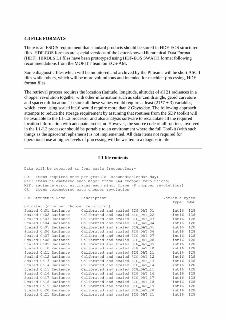
4.4 FILE FORMATS
There is an ESDIS requirement that standard products should be stored in HDF-EOS structuredfiles. HDF-EOS formats are special versions of the better-known Hierarchical Data Format(HDF). HIRDLS L1 files have been prototyped using HDF-EOS SWATH format followingrecommendations from the MOPITT team on EOS-AM.
Some diagnostic files which will be monitored and archived by the PI teams will be short ASCIIfiles while others, which will be more voluminous and intended for machine-processing, HDFformat files.
The retrieval process requires the location (latitude, longitude, altitude) of all 21 radiances in achopper revolution together with other information such as solar zenith angle, geoid curvatureand spacecraft location. To store all these values would require at least (21*7 + 3) variables,which, even using scaled int16 would require more than 2 Gbyte/day. The following approachattempts to reduce the storage requirement by assuming that routines from the SDP toolkit willbe available to the L1-L2 processor and also analysis software to recalculate all the requiredlocation information with adequate precision. However, the source code of all routines involvedin the L1-L2 processor should be portable to an environment where the full Toolkit (with suchthings as the spacecraft ephemeris) is not implemented. All data items not required foroperational use at higher levels of processing will be written to a diagnostic file
L1 file contents
Data will be reported at four basic frequencies:-
HD: items required once per granule (assumed=calendar day)MaF: items telemetered each major frame (64 chopper revolutions)MiF: radiance error estimates each minor frame (8 chopper revolutions)CR: items telemetered each chopper revolution
HDF Structure Name Description Variable Bytes Type /MaFCR data: (once per chopper revolution)Scaled Ch01 Radiance Calibrated and scaled SIG_DAT_01 int16 128Scaled Ch02 Radiance Calibrated and scaled SIG_DAT_02 int16 128Scaled Ch03 Radiance Calibrated and scaled SIG_DAT_03 int16 128Scaled Ch04 Radiance Calibrated and scaled SIG_DAT_04 int16 128Scaled Ch05 Radiance Calibrated and scaled SIG_DAT_05 int16 128Scaled Ch06 Radiance Calibrated and scaled SIG_DAT_06 int16 128Scaled Ch07 Radiance Calibrated and scaled SIG_DAT_07 int16 128Scaled Ch08 Radiance Calibrated and scaled SIG_DAT_08 int16 128Scaled Ch09 Radiance Calibrated and scaled SIG_DAT_09 int16 128Scaled Ch10 Radiance Calibrated and scaled SIG_DAT_10 int16 128Scaled Ch11 Radiance Calibrated and scaled SIG_DAT_11 int16 128Scaled Ch12 Radiance Calibrated and scaled SIG_DAT_12 int16 128Scaled Ch13 Radiance Calibrated and scaled SIG_DAT_13 int16 128Scaled Ch14 Radiance Calibrated and scaled SIG_DAT_14 int16 128Scaled Ch15 Radiance Calibrated and scaled SIG_DAT_15 int16 128Scaled Ch16 Radiance Calibrated and scaled SIG_DAT_16 int16 128Scaled Ch17 Radiance Calibrated and scaled SIG_DAT_17 int16 128Scaled Ch18 Radiance Calibrated and scaled SIG_DAT_18 int16 128Scaled Ch19 Radiance Calibrated and scaled SIG_DAT_19 int16 128Scaled Ch20 Radiance Calibrated and scaled SIG_DAT_20 int16 128Scaled Ch21 Radiance Calibrated and scaled SIG_DAT_21 int16 128

Elevation Angle Boresight elevation SC frame (nanoradians) int32 256Azimuth Angle Boresight azimuth SC frame(0.00005radians) int16 128Field Rotation Detector array about boresight(0.00001deg) int16 128Gyro El Correction Gyro correction to Elevation (nanoradians) int16 128Gyro Az Correction Gyro correction to Azimuth(0.00005radians) int16 128Flags Radiance and scan direction flags int32 128 Total bytes/MaF 3584c. 403 Mbyte/day
MiF data: (once per minor frame, 8 chopper revolutions)Scaled Ch01 Rad Error Scaled error estimate for Ch01 radiance int16 128Scaled Ch02 Rad Error Scaled error estimate for Ch02 radiance int16 128Scaled Ch03 Rad Error Scaled error estimate for Ch03 radiance int16 128Scaled Ch04 Rad Error Scaled error estimate for Ch04 radiance int16 128Scaled Ch05 Rad Error Scaled error estimate for Ch05 radiance int16 128Scaled Ch06 Rad Error Scaled error estimate for Ch06 radiance int16 128Scaled Ch07 Rad Error Scaled error estimate for Ch07 radiance int16 128Scaled Ch08 Rad Error Scaled error estimate for Ch08 radiance int16 128Scaled Ch09 Rad Error Scaled error estimate for Ch09 radiance int16 128Scaled Ch10 Rad Error Scaled error estimate for Ch10 radiance int16 128Scaled Ch11 Rad Error Scaled error estimate for Ch11 radiance int16 128Scaled Ch12 Rad Error Scaled error estimate for Ch12 radiance int16 128Scaled Ch13 Rad Error Scaled error estimate for Ch13 radiance int16 128Scaled Ch14 Rad Error Scaled error estimate for Ch14 radiance int16 128Scaled Ch15 Rad Error Scaled error estimate for Ch15 radiance int16 128Scaled Ch16 Rad Error Scaled error estimate for Ch16 radiance int16 128Scaled Ch17 Rad Error Scaled error estimate for Ch17 radiance int16 128Scaled Ch18 Rad Error Scaled error estimate for Ch18 radiance int16 128Scaled Ch19 Rad Error Scaled error estimate for Ch19 radiance int16 128Scaled Ch20 Rad Error Scaled error estimate for Ch20 radiance int16 128Scaled Ch21 Rad Error Scaled error estimate for Ch21 radiance int16 128 Total bytes/MaF 336c. 38 Mbyte/day
MaF data: (once per major frame, 64 chopper revolutions)Time Time of start of MaF (TAI) float64 8Latitude Reference point latitude (Degrees) float32 4Longitude Reference point long. ([-180,180]Degrees) float32 4Altitude Reference point altitud e (10metres) int16 2View Direction Boresight bearing at ref.pt.(0.01degrees) int16 2Solar Zenith Angle Ref. pt. solar zenith angle (0.01degrees) int16 2Local Solar Time Ref. pt. local solar time (0.001hours) int16 2Spacecraft Position ECI coordinates at start of MaF (cm) 3*int32 12Spacecraft Velocity ECI coordinates at start of MaF (mm/s) 3*int32 12Chopper Period (microseconds) int16 2Frame Counter HIRDLS frame counter int16 2HIRDLS Clock int16 2Scan Mode Identifier Scan mode identifier int16 2Warm Filter Temperature Calibrated LNS1WFTMP* (0.01K) int16 2Cold Filter Temperature Calibrated FPA_TEMP_* (0.01K) int16 2Wobble El Correction Wobble cor. to elevation (nanoradians) int16 2Scan El Error Elevation scan encoder error(nanoradians) int16 2Gyro El Error Error in Gyro El Corrrection(nanoradians) int16 2Wobble El Error Error in Wobble El Correction(nanoradians)int16 2FIR Filter Index Pointer to FIR filter coefficients int16 2 Total bytes/MaF 70c. 7.9 Mbyte/day
HD data: (once per granule, day)Data Date Nominal data date (TAI@00Z) float64 8Ch01 Scale Factor Scaling factor for Ch01 Rad and Rad_Error float32 4Ch02 Scale Factor Scaling factor for Ch02 Rad and Rad_Error float32 4Ch03 Scale Factor Scaling factor for Ch03 Rad and Rad_Error float32 4Ch04 Scale Factor Scaling factor for Ch04 Rad and Rad_Error float32 4

Ch05 Scale Factor Scaling factor for Ch05 Rad and Rad_Error float32 4Ch06 Scale Factor Scaling factor for Ch06 Rad and Rad_Error float32 4Ch07 Scale Factor Scaling factor for Ch07 Rad and Rad_Error float32 4Ch08 Scale Factor Scaling factor for Ch08 Rad and Rad_Error float32 4Ch09 Scale Factor Scaling factor for Ch09 Rad and Rad_Error float32 4Ch10 Scale Factor Scaling factor for Ch10 Rad and Rad_Error float32 4Ch11 Scale Factor Scaling factor for Ch11 Rad and Rad_Error float32 4Ch12 Scale Factor Scaling factor for Ch12 Rad and Rad_Error float32 4Ch13 Scale Factor Scaling factor for Ch13 Rad and Rad_Error float32 4Ch14 Scale Factor Scaling factor for Ch14 Rad and Rad_Error float32 4Ch15 Scale Factor Scaling factor for Ch15 Rad and Rad_Error float32 4Ch16 Scale Factor Scaling factor for Ch16 Rad and Rad_Error float32 4Ch17 Scale Factor Scaling factor for Ch17 Rad and Rad_Error float32 4Ch18 Scale Factor Scaling factor for Ch18 Rad and Rad_Error float32 4Ch19 Scale Factor Scaling factor for Ch19 Rad and Rad_Error float32 4Ch20 Scale Factor Scaling factor for Ch19 Rad and Rad_Error float32 4Ch21 Scale Factor Scaling factor for Ch21 Rad and Rad_Error float32 4Nominal IFC Temperature Nominal IFC temperature (K) float32 4Nominal CF Temperature Nominal cold filter temperature (K) float32 4Nominal WF Temperature Nominal warm filter temperature (K) float32 4Nominal Ch01 IFC Radiance (W/m^2/sr) float32 4Nominal Ch02 IFC Radiance (W/m^2/sr) float32 4Nominal Ch03 IFC Radiance (W/m^2/sr) float32 4Nominal Ch04 IFC Radiance (W/m^2/sr) float32 4Nominal Ch05 IFC Radiance (W/m^2/sr) float32 4Nominal Ch06 IFC Radiance (W/m^2/sr) float32 4Nominal Ch07 IFC Radiance (W/m^2/sr) float32 4Nominal Ch08 IFC Radiance (W/m^2/sr) float32 4Nominal Ch09 IFC Radiance (W/m^2/sr) float32 4Nominal Ch10 IFC Radiance (W/m^2/sr) float32 4Nominal Ch11 IFC Radiance (W/m^2/sr) float32 4Nominal Ch12 IFC Radiance (W/m^2/sr) float32 4Nominal Ch13 IFC Radiance (W/m^2/sr) float32 4Nominal Ch14 IFC Radiance (W/m^2/sr) float32 4Nominal Ch15 IFC Radiance (W/m^2/sr) float32 4Nominal Ch16 IFC Radiance (W/m^2/sr) float32 4Nominal Ch17 IFC Radiance (W/m^2/sr) float32 4Nominal Ch18 IFC Radiance (W/m^2/sr) float32 4Nominal Ch19 IFC Radiance (W/m^2/sr) float32 4Nominal Ch20 IFC Radiance (W/m^2/sr) float32 4Nominal Ch21 IFC Radiance (W/m^2/sr) float32 4TRCF to SFR Matrix TRCF to SFR (3x3)Transformation Matrix 9*float64 72FIR Coefficient Set 1 1st set of 32 FIR coefficients 32*float64 256FIR Coefficient Set 2 2nd set of 32 FIR coefficients 32*float64 256FIR Coefficient Set 3 3rd set of 32 FIR coefficients 32*float64 256FIR Coefficient Set 4 4th set of 32 FIR coefficients 32*float64 256FIR Coefficient Set 5 5th set of 32 FIR coefficients 32*float64 256FIR Coefficient Set 6 6th set of 32 FIR coefficients 32*float64 256FIR Coefficient Set 7 7th set of 32 FIR coefficients 32*float64 256FIR Coefficient Set 8 8th set of 32 FIR coefficients 32*float64 256 Total Bytes/granule 2308Expected Size of L1 file = 449 Mbytes/day
Notes:-
'Radiance' and 'Rad Error' data items are expressed as fractions of theIFC radiance at a specified nominal temperature (TBD c290K).To exploit the dynamic range of int16 storage the following relationshipis used
Fractional IFC radiance = (Scaled radiance + 16384) * Scale Factor
Scale factors are channel dependent but are typically about 0.00003.

The same scaling is used for 'Rad Error'.
Gyro and wobble corrections are included in the 'Elevation' and 'Azimuth'data but are also included as separate items in the L1 file so thatthese terms can be studied without re-running the L0-L1 processor.
'Field Rotation' is the angle between the detector array vertical and theplanedefined by the bore-ray vector and a vector from the spacecraft to theearth centre (ECI origin). This is nominally zero.
Flags will indicate direction of vertical and horizontal scanningsand flag bad radiance data.
Bit 0 - bit set if not part of nominal (10s) vertical scan Bits 1-21 - bit set if corresponding rad_ value should not be used e.g. frame contains checksum/parity error etc radiance value contaminated (obstruction in FOV) etc radiance could not be calibrated detector elements too warm etc Bits 22-25 - unused Bit 26 - bit set if all channels contain valid space view Bit 27 - bit set if valid IFC BB view Bit 28 - bit set if scanning left (away from IFC) Bit 29 - bit set if scanning right (towards IFC) Bit 30 - bit set if scanning up (towards space) Bit 31 - bit set if scanning down (towards earth)
The reference point is defined to be the boresight tangent point at thestart of the major frame. All reference point data is nominal andis included only to allow easy data analysis and sub-setting where highaccuracy is not required.
The nominal IFC radiance data are the radiances (in W/m^2/sr) for eachchannelwhere the black body is at the nominal temperature ('Nominal IFCTemperature')and the filter functions are appropriate to the nominal filter temperatures('Nominal WF Temperature' and 'Nominal CF Temperature'). This information isprovided only so that the fractional radiances stored in the file can bequickly approximated in standard units.
One set of 32 FIR coefficients (the same for all channels) is used foreach of four mission sub-modes: GM0 (21 channels sampled), SP1(10 channels sampled), SP2 (7 channels sampled) and SP3 (3 channels sampled).The maximum number of sets of coefficients to be used in a day is TBDbut a value of 8 has been used for prototyping activities.
Diagnostic file contents
Basically this contains all the calibrated data not in the L1 file.
Things that could be added include1) Radiances calibrated without any non-linearity, or scan stray correction2) Spacecraft ephemeris and attitude data
Things that might not be needed (but do not take much space) include1) Telemetry from a few redundant systems2) s/w build identifiers
There will be two data types:-one for items telemetered each chopper revolution, CR

one for items telemetered each major frame, MaF, (64 chopper revolutions) BytesR data: /MaFclock_lsb HIRCLKLSB HIRDLS clock LSB int*8 64gyr_angle[0:3] Calibrated GYR*_ADAT Gyro * angle data 4*int16 512elev[1:2] Calibrated ELEVDATA Elevation encoder * 2*int16 256azim Calibrated AZIMDAT Azimuth encoder int16 128
MaF data:ifc_bb_temp[1:3] Cal. IFCBB_TMP* IFC Black Body temp 3*int16 6ifc_plate_temp Calibrated IFCBB_FRPL_TMP IFCBB front plate temp int16 2ifc_oven_temp Calibrated IFC_OVEN_TMP Ref. resistor oven temp int16 2ifc_p28_v Calibrated IFC_PSV_P28 IFC +28V rail volts int16 2ifc_p15_v Calibrated IFC_PSV_P15 IFC +15V rail volts int16 2ifc_n15_v Calibrated IFC_PSV_N15 IFC -15V rail volts int16 2ifc_p5_v Calibrated IFC_PSV_P5 IFC +5V rail volts int16 2sail_00_param[0:15] SAILTASK00_* SAIL Task 0 params 16*int16 32sail_01_param[0:15] SAILTASK01_* SAIL Task 1 params 16*int16 32sail_02_param[0:15] SAILTASK02_* SAIL Task 2 params 16*int16 32sail_03_param[0:15] SAILTASK03_* SAIL Task 3 params 16*int16 32sail_04_param[0:15] SAILTASK04_* SAIL Task 4 params 16*int16 32sail_05_param[0:15] SAILTASK05_* SAIL Task 5 params 16*int16 32sail_06_param[0:15] SAILTASK06_* SAIL Task 6 params 16*int16 32sail_07_param[0:15] SAILTASK07_* SAIL Task 7 params 16*int16 32sail_08_param[0:15] SAILTASK08_* SAIL Task 8 params 16*int16 32sail_09_param[0:15] SAILTASK09_* SAIL Task 9 params 16*int16 32sail_10_param[0:15] SAILTASK10_* SAIL Task 10 params 16*int16 32sail_11_param[0:15] SAILTASK11_* SAIL Task 11 params 16*int16 32sail_12_param[0:15] SAILTASK12_* SAIL Task 12 params 16*int16 32sail_13_param[0:15] SAILTASK13_* SAIL Task 13 params 16*int16 32sail_14_param[0:15] SAILTASK14_* SAIL Task 14 params 16*int16 32sail_15_param[0:15] SAILTASK15_* SAIL Task 15 params 16*int16 32sail_mem[504:511] SAIL_SHM_* SAIL shared memory 8*int32 32sail_att_stat[0:3] SAILCMDST_* SAIL cmd att. status 4*int32 16sail_pstatus SAIL_PROC_STAT SAIL Proc. Status int8 1sail_tstatus[0:15] SAILTSKSTAT_* SAIL Task Status 16*int8 16sail_cmd_recd SLCMDS_RCVCT SAIL cmds: recvd count int16 2sail_cmd_reject SLCMDS_REJCT SAIL cmds: reject cnt. int16 2sail_cmd_result SLCMD_LAST_RC Last cmd: result code int16 2sail_cmd_number SLCMD_LAST_CN Last SAIL cmd: number int16 2gyr_temp[0:3] Calibrated GYR*_TEMP Gyro temperatures 4*int16 8gyr_board_temp[0:3] Cal. GYR*_BDTMP Gyro board temps 4*int16 8gyr_magnet[0:3] Cal. GYR*_MAGDAT Magnetometer data 4*int16 8gyr_capl[0:3] GYR*_CAPL Gyro cap loop output 4*int16 8gyr_motor_v[0:3] Cal. GYR*_MOTV Gyro motor volts 4*int16 8gyr_motor_i[0:3] Cal. GYR*_MOTC Gyro motor current 4*int16 8gyr_status[0:3] GYR*_STAT Gyro status words 4*int16 8gyr_p15_v[0:3] Calibrated GYR*_P15V Gyro +15 volt levels 4*int16 8gyr_n15_v[0:3] Calibrated GYR*_N15V Gyro -15 volt levels 4*int16 8sc_data[0:7] ORB_DAT_* S/C Ancillary data 8*int16 16m1_temp[1:3] Calibrated M1TMP* Pri. M1 mirror temp. 3*int16 6chopper_temp[1:3] Cal. CHOPHSGTMP* Chopper housing temp 3*int16 6cal_mirror_temp[1:3] Cal. CALMIRTMP* Cal. Mirror temps 3*int16 6m2_temp[1:2] Calibrated M2TMP* Sec. M2 mirror temp 2*int16 4spv_mirror_temp[1:3] Cal. SPVUMIRTMP* Chop. ref. Mir. temp 3*int16 6struct_temp[1:4] Cal. STH_TMP_* Structure temps. 4*int16 8ccu_box_temp Calibrated CCUBOXTMP CCU box temperature int16 2geu_box_temp Calibrated GEUBOXTMP GEU box temperature int16 2pcu_box_temp Calibrated PCUBOXTMP PCU box temperature int16 2beu_box_temp Calibrated BEUBOXTMP BEU box temperature int16 2beu_mount_temp Calibrated BEUMNTTMP BEU mount temperature int16 2spu_box_temp Calibrated SPUBOXTMP SPU box temperature int16 2ipu_box_temp Calibrated IPUBOXTMP IPU box temperature int16 2teu_box_temp Calibrated TEUBOXTMP TEU box temperature int16 2

teu_mount_temp Calibrated TEUMNTTMP TEU mount temperature int16 2eea_mount_temp Calibrated EEAMNTTMP EEA mount temperature int16 2eea_box_temp Calibrated EEABOXTMP EEA box temperature int16 2sunsensor_temp[1:3] Cal. SUNSEN*_TMP Sun sensor temps. 3*int16 2door_angle Calibrated DOOR_POT Door angle sensor int16 2door_safe Calibrated DOOR_SAF_ANG Door Safe Angle settingint16 2wax_temp Calibrated SSHWA_TMP Hot Wax Actuator temp. int16 2ssh_motor_temp Calibrated SSH_DORMOT_TMP SSH drive motor temp. int16 2ssh_plate_temp Calibrated SSH_APL_TMP SSH aperture plate tempint16 2ssh_pz_temp Calibrated SSH_PZSURF_TMP SSH +Z surface temp. int16 2ssh_nz_temp Calibrated SSH_NZSURF_TMP SSH -Z surface temp. int16 2ssh_status SSH_STATUS Sunshield switch status int8 1sva_status SVA_STATUS SVA switch status int8 1sva_motor_temp Calibrated SVA_DORMOT_TMP SVA drive motor temp int16 2sva_plate_temp Calibrated SVA_MTGPLT_TMP SVA mounting plate tempint16 2eea_status EEA_STATUS EEA config. status int16 2el_motor1_i[0:7] Cal. ELMOTR1_CRRT Elev motor 1 current 8*int16 16el_motor2_i[0:7] Cal. ELMOTR2_CRRT Elev motor 2 current 8*int16 16az motor_i Calibrated AZMOTR_CRRT Azimuth motor current int16 2chopper_i Calibrated CHOPMOT_CRRT Chopper motor current int16 2teu_sw_status TEU_TSW_STAT Telescope S/W Status int16 2teu_proc_status TEU_STATUS TEU Processor Config. int8 1tss_hw_status TSS_HW_CFIG TSS hardware config. int16 2tss_sigcon_status TEU_SIGCON_STAT TEU Sig Cond Data Acq int8 1scan_motor_status SCAN_MOT_STAT Scan Mir. motor status int16 2teu_adc_ref_v[0:3] Cal. TEU_ADC*_REF TEU ADC +5V ref. 4*int16 8teu_adc_zero_v[0:3] Cal. TEU_ADC*_ZER TEU ADC +5V zero 4*int16 8teu_p5_v Cal. TEU_P5V TEU +5V rail voltage int16 2teu_p9_v Cal. TEU_P9V TEU +9V rail voltage int16 2teu-n9_v Cal. TEU_N9V TEU -9V rail voltage int16 2scan_mir_temp[1:3] Cal. SMTMP* Scan mirror temps 3*int16 6el_motor1_temp[1:2] Cal. ELMOT1TMP* Elev. motor 1 temps 2*int16 4el_motor2_temp[1:2] Cal. ELMOT2TMP* Elev. motor 2 temps 2*int16 4az_motor_temp Cal. AZMOTTMP Azimuth motor temp int16 2oba_base_temp Cal. SCAN_BASE_TMP OBA Scanner base temp int16 2oba_lens_temp[1:2] Cal. LNSASSY_TMP* OBA lens asmbly temp.2*int16 4oba_baffle_temp Cal. SPVU_BAF_TMP OBA Space View baffle int16 2oba_plate_temp Calibrated OBA_PLT_TMP OBA aperture plate int16 2gmu_mount_temp Calibrated GMU_MNT_TMP GMU Mount temperature int16 2gmu_house_temp Calibrated GMU_HSG_TMP GMU Housing temp. int16 2tsw_build_id TSW_CSCI_BUILD_ Telescope S/W Version int16 2fpa_temp[1:2] Calibrated FPA_TEMP_* Focal Plane temps 2*int16 4tmark_clock TMARK_CLK Time Mark clock word int16 2tmark_data TMARK_DATA Time mark data word int16 2sc_cmd_recd SCCMDS_RCVCT S/C cmds: receivd cnt. int16 2sc_cmd_reject SCCMDS_REJCT S/C cmds: reject count int16 2sc_cmd_result SCCMD_LAST_RC Last cmd: result code int16 2sc_cmd_number SCCMD_LAST_CN Last S/C cmd: number int16 2sc_cmd_packet SCCMD_LAST_PC Last packet. seq. cnt. int16 2macro_cmd_recd MACMDS_RCVCT Macro cmds: recd count int16 2macro_cmd_reject MACMDS_REJCT Macro cmds: reject cnt.int16 2macro_cmd_result MACMD_LAST_RC Last cmd: result code int16 2macro_cmd_number MACMD_LAST_CN Last Macro cmd: number int16 2minor_frame_count[0:7] FRAMECNT Minor frame count 8*int8 8hsk_format[0:7] HK_FORMAT_ID H'keeping format 8*int16 16sig_sero[1:21] SIG_ZERO_* Signal chan offset 21*int16 42spu_ap5_v[1:2] Calibrated SPU_P5VOLTS_* SPU +5V (analog) 2*int16 4spu_an5_v[1:2] Calibrated SPU_N5VOLTS_* SPU -5V (analog) 2*int16 4spu_dp5_v[1:2] Calibrated SPU_P5VOLTS_D* SPU +5V (dig) 2*1nt16 4spu_p12_v[1:2] Calibrated SPU_P12VOLTS_* SPU +12V supply 2*int16 4spu_n12_v[1:2] Calibrated SPU_N12VOLTS_* SPU -12V supply 2*int16 4ipu_p3_v Calibrated IPU_3P3VOLTS Wkg IPU +3.3V supply int16 2ipu_p5_v Calibrated IPU_5VOLTS Wkg IPU +5V supply int16 2ipu_p15_v Calibrated IPU_P15VOLTS Wkg IPU +15V supply int16 2
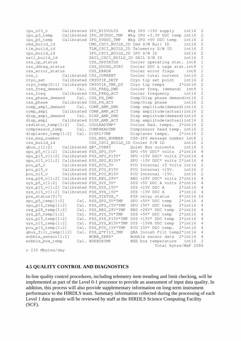
ipu_n15_v Calibrated IPU_N15VOLTS Wkg IPU -15V supply int16 2ipu_p3_temp Calibrated IPU_3P3DDC_TMP Wkg IPU +3.3V DDC temp int16 2ipu_p5_temp Calibrated IPU_5VDDC_TMP Wkg IPU +5V DDC temp int16 2cmd_build_id CMD_CSCI_BUILD_ID Cmd S/W Buil ID int16 2tlm_build_id TLM_CSCI_BUILD_ID Telemetry S/W ID int16 2ipu_build_id IPU_CSCI_BUILD_ID IPU S/W ID int16 2sail_build_id SAIL_CSCI_BUILD_ID SAIL S/W ID int16 2css_op_status CSS_OPSTATUS Cooler operating stat. int8 1css_ddcag_status CSS_DDCAG_STAT Cooler DDC & cage stat.int8 1css_error_status CSS_ERROR Cooler error flags int8 1css_i Calibrated CSS_CURRENT Cooler total current int16 2cryo_set Calibrated CRYOTIP_SETP Cryo tip set point int16 2cryo_temp[0:1] Calibrated CRYOTIP_TMP_D0 Cryo tip temps 2*int16 2css_freq_demand Cal. CSS_FREQ_DMD Cooler freq. (demand) int8 1css_freq Calibrated CSS_FREQ_ACT Cooler frequency int16 2css_phase_demand Cal. CSS_PH_DMD Comp/Disp phase demandint16 2css_phase Calibrated CSS_PH_ACT Comp/Disp phase int16 2comp_ampl_demand Cal. COMP_AMP_DMD Comp amplitude(demand)int16 2comp_ampl Calibrated COMP_AMP_ACT Comp amplitude(actual)int16 2disp_ampl_demand Cal. DISP_AMP_DMD Disp amplitude(demand)int16 2disp_ampl Calibrated DISP_AMP_ACT Disp amplitude(actual)int16 2radiator_temp[1:2] Cal. COOLRADTMP* Cooler Rad. temps. 2*int16 2compressor_temp Cal. COMPHEADTMP Compressor head temp. int16 2displacer_temp[1:2] Cal. DISPL*TMP Displacer temps. 2*int16 2css_msg_number CSS_MSG_NUMBER CSS-IPS message number int8 1css_build_id CSS_CSCI_BUILD_ID Cooler F/W ID int16 2qbus_i[1:2] Calibrated QB*_CURRT Quiet Bus currents int16 2spu_p5_v[1:2] Calibrated PSS_SPU_5V* SPU +5V DDC* volts 2*int16 4spu_p15_v[1:2] Calibrated PSS_SPU_P15V* SPU +15V DDC* volts 2*int16 4spu_n15_v[1:2] Calibrated PSS_SPU_N15V* SPU -15V DDC* volts 2*int16 4pcu_p5_v Calibrated PSS_PCU_5V PCU Internal +5 Volts int16 2pcu_p15_v Calibrated PSS_PCU_P15V PCU Internal +15V. int16 2pcu_n15_v Calibrated PSS_PCU_N15V PCU Internal -15V. int16 2reg_p28_v[1:2] Calibrated PSS_REG_28V* REG +28V DDC* volts 2*int16 4sys_p5_v[1:2] Calibrated PSS_SYS_5V* SYS +5V DDC A volts 2*int16 4sys_p15_v[1:2] Calibrated PSS_SYS_15V* SYS +15V DDC A 2*int16 4sys_n15_v[1:2] Calibrated PSS_SYS_15V* SYS -15V DDC A 2*int16 4pss_status[0:7] PSS_STATUS_* PSS relay status 8*int16 16spu_p5_temp[1:2] Cal. PSS_SPU_5V*TMP SPU +5V* DDC temp 2*int16 4spu_p15_temp[1:2] Cal. PSS_SPU_15V*TMP SPU 15V* DDC temp 2*int16 4reg_p28_temp[1:2] Cal. PSS_REG_28V*TMP REG +28V* DDC temp 2*int16 4sys_p5_temp[1:2] Cal. PSS_SYS_5V*TMP SYS +5V* DDC temp 2*int16 4sys_p15_temp[1:2] Cal. PSS_SYS_P15V*TMP SYS +15V* DDC temp 2*int16 4sys_n15_temp[1:2] Cal. PSS_SYS_N15V*TMP SYS -15VA DDC temp 2*int16 4pcu_p15_temp[1:2] Cal. PSS_PCU_15V*TMP PCU 15V* DDC temp. 2*int16 4qbus_filt_temp[1:2] Cal. PSS_Q*FILT_TMP QBA Inrush Filt temp2*int16 4wobble_sensor[1:2] WOBB_SENS* Wobble sensor data 2*int16 4wobble_box_temp Cal. WSEBOXTMP WSE box temperature int16 2 Total bytes/MaF 2086c 235 Mbytes/day
4.5 QUALITY CONTROL AND DIAGNOSTICS
In-line quality control procedures, including telemetry item trending and limit checking, will beimplemented as part of the Level 0-1 processor to provide an assessment of input data quality. Inaddition, this process will also provide supplementary information on long-term instrumentperformance to the HIRDLS team. Summary information collected during the processing of eachLevel 1 data granule will be reviewed by staff at the HIRDLS Science Computing Facility(SCF).

4.6 EXCEPTION HANDLING
The Level 0-1 processor must be robust enough to behave predictably when supplied with anycorrupt data. Because of its origin and routing the raw L0 data can be a particular problem in thisregard. Checksums and other data quality indicators will be inspected before any data areprocessed. Some further exception handling is effectively performed by the limit checkingprocedures mentioned in Section 4.5 above. Floating point exceptions should not be a majorproblem. Underflow to zero will be acceptable to all HIRDLS algorithms. Overflow is unlikelygiven the magnitude of the numbers in the telemetry will be limit checked. Code will bedesigned to avoid division by zero which is the most probable cause of a floating point exceptionin the Level 0-1 processor.
4.7 CODING STANDARDS
It is expected that the L0 to L1 processor will be written in Fortran because it is more familiarthan C to those actively involved in this work. Similar coding standards will be applied to thoseused successfully with the ISAMS and MOPITT projects. Decremental features identified by theANSI Fortran Language committee and recognised by ISO will not be used. To avoidunnecessary complexity and to assist in the task of long-term code maintenance use only of thoseconstructs included in the ELF and F subset languages will be encouraged.
5. APPENDICES
5.1 APPLICABLE DOCUMENTS
The High Resolution Dynamics Limb Sounder (HIRDLS): an instrument for the study of globalchange. Gille, J. C. and J. J. Barnett, pp 439-450, in The use of EOS for Studies for AtmosphericPhysics, ed Gille, J.C and G. Visconti, North Holland, Amsterdam, 1992.
HIRDLS Instrument Technical Specification, SP-HIR-013T, January 1999.
HIRDLS Science Software Management Plan, SC-HIR-133, December 1997.
HIRDLS Science Data Management Plan, SC-HIR-135, December 1997.
Theoretical Basis of the SDP Toolkit Geolocation Package for the ECS Project,445-TP-002-002,May 1995, Hughes Information Technology Systems, Landover, Maryland.
Version 2.0 SDP Toolkit Users Guide, 333-CD-100-001, June 1998,Raytheon Systems Company, Upper Marlboro, Maryland.
HDF-EOS User's Guide for ECS Project Volume 1, 170-TP-100-001, June 1998,Hughes Information Technology Systems, Landover, Maryland.
HDF-EOS User's Guide for ECS Project Volume 2, 170-TP-101-001, June 1998,Hughes Information Technology Systems, Landover, Maryland.

5.2 CHEM-1/SOLSTICE ATBD REVIEW, MAY 18-19, 1999.
5.2.1 Questions Received Prior to Oral Presentation
12 May 1999
1. The value of the gyro is questioned. The system still seems to be limited by mirrorencoder error. The gyro can only help with movements that will perfectly couple to themirror (at a frequency less than chopper rotation). However, it is not likely to be criticalto results. Twenty-metre precision on pressure surfaces over 500km seems unlikely.
2. Channel alignment - How will attitude be verified in orbit, especially considering thecurved limb ?
3. No FOV functions are shown. What will be their shape and how will they be calibrated ?
4. Signal offset variation as a function of view direction could contain thermaldependencies. How will this be addressed ?
5. How will off-axis scatter be monitored, and calibrated in orbit if necessary ?
6. How will filter bandpass temperature dependence be handled ?
7. No discussion of instrument time response is presented. We assume the bandpass will bevery wide, but if wider than the sampling nyquist, S/N will be sacrificed.
5.2.2 Outline of responses given at Oral Presentation
18 May 1999
1. The use of gyroscopes is fundamental to the instrument design. However accurate themirror encoder this only measures position relative to the optical bench and, on aspacecraft such as CHEM which will be subject to a lot of vibration, it is essential thatthe motion of the optical bench is measured as well as possible. Gyroscopes provide asuitable method of doing this.
The scan mirror elevation encode will be much more precise than the question suggested,with a single sample r.m.s. errors of approximately 0.4 arcsec line-of-sight, whichcorresponds to 6m at the tangent point. Without gyro measurements, the motions of theoptical bench would be the dominant source of pointing error.
2. Channel alignment may be verified in orbit by observation of bright celestial bodies.During the discussion it was suggested that the Earth surface could sometimes be usedover deserts and possibly the Antarctic plateau; ISAMS was believed to have seen thesurface over deserts.
3. The instrument field of view is not used in the Level 0 - 1 processing and consequently isnot addressed in this ATBD. The field of view of each channel will measured in pre-launch testing. Two possible methods by which this information may be used in theforward model in Level 1 - 2 processing have been identified (ref. ATBD-HIRS-02).
4. Section 3.8 Radiometric Calibration does not make it clear that an estimate of thevariation of signal offset with view direction is made each vertical scan (roughly every 10seconds). The thermal characteristics of the (thermostated) instrument are expected tovary primarily at orbital rate (roughly every 6000 seconds). It is expected that thisinformation will enable us to model any thermal dependencies. The approach to the

correction for scan-dependent radiances will be validated during spacecraft "pitch down"manoeuvres.
5. The effect of scatter inside of the scan mirror should be completely corrected for by in-orbit calibration when the view is to space (assumed zero radiance) obtains the zeroradiance signal. This is because the viewing geometry remains constant.
Outside the scan mirror, the viewing geometry remains relatively constant within eachelevation scan, hence to a good approximation the effect of scatter will also be taken outby using the space view signal for the given azimuth angle as a zero point calibration forthat same azimuth angle. This will will be measured as part of the scanning sequence formeasuring the profile; hence every profile will have its own near-coincident set of zeroradiance signal measurements. However it is accepted that there will be factors (notablyscatter from the scan mirror and variation of scan mirror emissivity with mirror angle)which cause a variation of the zero radiance signal with mirror angle) which cause avariation of the zero radiance signal with mirror angle. Hence provision is being made formaking a correction: the scan mirror will be moved sufficiently far (20km TBV) abovethe lowest tangent altitude needed to obtain an effective zero radiance view so that therate of change of signal with elevation angle can also be obtained as described in Section3.8. This trend can then be applied to lower altitudes. It will be possible to enable ordisable this feature in data processing. Study of the variation of space signal zero thusobtained with azimuth and possibly latitude and longitude should enable informationabout scattering and mirror emissivity to be obtained by offline processing, including byfitting against models which incorporate the expected variations.
6. See last paragraph of Section 3.8 Radiometric Calibration. Note that the band-definingwarm filter is thermostatted.
7. The signal processing chain involves an analogue system including analogue filterswhich produce a a digitised data value every half chopper cycle (at a phase relationshipwhich is commandable separately for each channel), i.e. 1000 samples per second. Thesedata are filtered in the instrument processor using a FIR filter with coefficients which canbe changed by command, to lead to a telemeterd data value every chopper rotation, i.e. 6chooper cycles or 12msec nominal. The FIR filter coefficients will be selected with atrade-off study jointly to maximise the vertical resolution and minimise noise, and this isexpected to have the effect that each radiometric sample is nearly independent of itsneighbour.
5.2.3 Recommendations received from the Review Panel
15 July 1999
The HIRDLS Executive Summary of the EOS CHEM-1 ATBD Review Panel Report did notdistinguish between the two ATBDs presented. Of the total of seven recommendations only threemight be applied to HIRS-ATBD-01.
"Embarking on a new development could delay the start of detailed modeling of retrieval errorsin a full-up system. The required fidelity and accuracy performance may take years to achieve,considering the likely limited time available to those on the team who are capable of developingsuch models."
• "Recommendation 1 - Evaluate available code before embarking on new development.Even if performance is marginal, put code in place to allow rapid and robust processingsimulations to commence ASAP. Insert new developments as they become available."

"The mission is depending on gyro information and real-time spacecraft attitude information forreliable channel alignment, which is crucial to accurate retrievals"
• "Recommendation 3 - Position identical CO2 bandpass filters on opposite sides of thedetector focal plane (duplicate CO2 channels) and offset in the vertical. This allowsalignment of these CO2 channels to be inferred from the data, effectively validating thechannel alignment process. They also serve as a backup method of channel alignmentshould gyro and attitude data become unreliable. By offsetting in the vertical, they couldserve as sensors for attitude motion in the scan plane, although care must be taken todistinguish motion from twist about the boresight and Earth oblateness effects."
"There are two important aspects of the HIRDLS instrument which have direct impact on thesuccessful operation of the instrument. One is the ability to use a model of scan mirror responseversus scan angle to extrapolate the calibration information provide [sic] by viewing the IFC tolimb scenes. The HIRDLS plan is to determine the mirror response using orbital maneuvers tomake azimuthal and elevation scans of deep space. These measurements would then be input to aresponse versus scan angle model of the scan mirror, the output of which would be applied in thecalibration of various limb data. Preflight, laboratory measurements of the reflectance (oremissivity) of the the scan mirror at the azimuthal/elevation angles corresponding to views of theIFC could be compared to lab measurements at limb viewing angles. However, extrapolation ofthese preflight measurements to the on-orbit situation requires some assumptions concerning thepresence or lack of on-orbit directional degradation of mirror reflectance. The HIRDLSinstrument and science team are well aware of these challenges."
"The second important aspect of the HIRDLS instrument is the potential launch/on-orbitregistration-related problem of the focal plane shifting relative to the instrument optics. Duringthe discussion of this topic, views of the Moon, stars, and strategically selected portions ofAntarctica were suggested as means to provide registration information in the event of a focalplane/optics shift. This strategy needs to be examined more closely and developed more fully."
• "Recommendation 5 - Look at ways to verify that internal offset is constant with scanmirror position. It appears that this is assumed for the IFC look position. Estimatepossible error due to this assumption."
5.2.4 Responses to Review Panel Recommendations
Recommendation 1:
No significant code has been identified which could be re-used for HIRDLS Level 0 - Level 1processing. Obviously experience and ideas developed for ISAMS and for the HIRDLScalibration and test facility will be exploited wherever appropriate.
Recommendation 3 - from John Barnett, HIRDLS UK PI :-
The point is taken; however the time when such changes could have been made in the focal planedesign passed at least a year ago because of the long lead time on the manufacture. To haveadded elements to the set of 21 would have caused optical problems, hence there would havebeen a very difficult decision as to which of the current passbands to replace. Currently it isbelieved that the pointing knowledge obtained from the gyroscope subsystem will be sufficient,after special in-orbit calibrations to determine small constant offsets. It should be noted that the 5temperature sounding channels in the 15 micron carbon dioxide band were all placed in the same(central) column of the array specifically to provide sets of radiances which are mutually selfconsistent to a very high degree, i.e. for the sort of considerations mentioned by the Panel.

Recommendation 5 - from Christopher W P Palmer, HIRDLS Instrument Calibration Scientist :-
The Panel have correctly identified two concerns of the HIRDLS instrument and science team inthe area of radiometric calibration and forward modelling. However the concern as stated isincorrect in detail.
1. Effects due to variation of Scan Mirror properties with angle.
There is an issue here, but it does not relate to gain calibration as such. The variation ofreflectance with angle of incidence is extremely small for a good reflector: for a cleanmetal surface with normal reflectance of 97.0%, the (polarization averaged) reflectance at40 degrees is 96.9%, a variation which is probably less than the precision of pre-launchreflectance data. The upper limit in gain error from this source is thus 0.1%, and this is infact a considerable overestimate because of a fundamental radiometric compensationmechanism - the gain error consists of this reflectance change multiplied by the fractionaldifference in Planck function between scan mirror and IFC, which reduces the error byabout a factor of 5. This makes it a very small component of the overall gain error budget(1% total), and questions of extrapolating mirror properties to the IFC view are simplyirrelevant.
The concern relates to the consequent angle-variation in emission by the scan mirror,which leads to a variable offset. This error is only significant for scenes with lowradiance (high altitude or aerosol channels). The offset variation is, in the worst cases, afew times the random noise, and will be handled as described in section 3.8. Data fromorbital manouvres may be used to validate this procedure.
2. Possible launch shift of focal plane/optics alignment.
This is recognised as a critical area, as microns of relative movement between the focalplane assembly and the remainder of the optics can lead to changes in either overall line-of-sight or defocus. In fact the more significant error may well be the defocus. Overallabsolute alignment knowledge is not required to high accuracy, only relative aligmentchanges between views, and between channels. Launch shifts in channel co-alignment areunlikely, and post-launch changes on the overall alignment of the (thermostatted) focalplane are not expected. However some change in the as-measured field-of-view shapesdue to launch shifts is possible, and the treatment of field-of-view in Level 2 must takeaccount of this. Special observations of the Moon or selected surface targets are unlikelyto give useful data on absolute aligment (unless the change is so gross that we have noidea where we are looking) as the instrument is a radiometer and not an imager, and areeven less likely to give useful data on FOV shape, as the measurement conditions areinadequately controlled.
In addition, we share many of the general concerns expressed in the report (Section II.3). Inparticular we note the comments about systematic errors and agree that more emphasis needs tobe placed on the reduction of these. However, the treatment of systematic errors often entails off-line analysis of flight data and does not form part of the data processing algorithms described inthe ATBD.
5.3 ACRONYMS and ABBREVIATIONS
CSS Cooler Sub-SystemECI Earth Centered Inertial Reference Frame (J2000)

ECIS ECI reference frame with instantaneous with spacecraft velocityFPA Focal Plane AssemblyGEU Gyroscope Electronics UnitGMU Gyroscope Mounting UnitHIRDLS High Resolution Dynamics Limb Sounder (EOS CHEM experiment)IFC In-Flight CalibratorIFOV Instrument Field Of ViewIPU Instrument Processor UnitIRCF Instrument Reference Coordinate frameISAMS Improved Stratospheric and Mesospheric Sounder (UARS experiment)ISO International Standards OrganisationLIMS Limb Infrared Monitor of the Stratosphere (NIMBUS 7 experiment)MOPITT Measurement of Pollution in The Troposphere (EOS AM experiment)OBA Optical Bench AssemblyPOA Principal Optical AxisPSS Power Sub-SystemSAIL Science Algorithm Implementation LanguageSCF Science Computing FacilitySDP Science Data ProcessingSFR Spacecraft Frame of ReferenceSPU Signal Processing UnitSRCF Spacecraft Reference Coordinate FrameSSH Sun-ShieldSVA Space View ApertureTEU Telescope Electronics UnitTRCF Telescope Reference Coordinate FrameTSS Telescope Sub-SystemUARS Upper Atmosphere Research Satellite