hip ntenna guide for chinese amr band - silicon labs · an795 4 rev. 0.1 2.7. radiation pattern the...
TRANSCRIPT

Rev. 0.1 6/14 Copyright © 2014 by Silicon Laboratories AN795
AN795
WHIP ANTENNA GUIDE FOR CHINESE AMR BAND
1. IntroductionThis document provides guidelines for selecting whip antenna in 490M band. It also describes the performance ofthree different 50 single-ended antennas which are used in the 470–510 MHz Chinese AMR band and arededicated to the EZRadio and EZRadioPRO family.
Section “2. Basic Antenna Parameters” describes the antenna concept and parameters (such as gain, direction,etc.,) that are related to the antenna performance when selecting an antenna.
Section “3. Antenna Classifications and Their Applications” introduces the antenna classification and applicationcase of the PCB antenna, chip ceramic antenna, and whip antenna according to their performances.
Section “4. Whip Antenna Performance Test” describes the performance evaluation for the three selected whipantennas.
The antennas are selected for 470–510 MHz band. The antennas are optimized and tuned under the antenna PCB+ Pico Board + Motherboard (MSC-WMB930 Wireless Motherboard) structure (see Figure 1).
Figure 1. Typical Measurement Configuration—Antenna, Pico Board, and Wireless MotherboardThe input impedance and antenna gain of all whip antennas are measured with the above configuration. Theoutdoor range is also checked using two identical antenna modules.

AN795
2 Rev. 0.1
2. Basic Antenna Parameters 2.1. Input ImpedanceInput impedance is defined as the impedance presented by the antenna at its terminals or the ratio of the voltage tocurrent at its terminals. If the antenna is not matched to the feed line, a standing wave is induced along the feedline. The ratio of the maximum voltage to the minimum voltage along the line is called the Voltage Standing WaveRatio (VSWR). The impedance can also be expressed in another format as S11 if it is normalized to 50 .
2.2. DirectivityThe directivity is a measurement that describes the directional transmitting properties of the antenna. It is definedas the ratio of the antenna radiation intensity in a specific direction in space over the radiation intensity of anisotropic source for the same radiated power. There are cases in which the term directivity is implied to refer to itsmaximum value.
2.3. Antenna GainAntenna gain is closely related to the directivity, but includes the losses in the antenna as well as its directionalcapabilities. Antenna gain has the following characteristics:
Refers to the direction of maximum radiation.
Is a dimension-less factor related to power and usually expressed in decibels.
Gi “Isotropic Power Gain” is a theoretical concept; the reference antenna is isotropic.
Gd of the reference antenna is a half-wave dipole.
2.4. EfficiencyThe antenna efficiency is the ratio of directivity to gain. It accounts for all the power lost before radiation. Thelosses may be due to mismatch at the input terminals, conduction losses, dielectric losses and spill-over losses.
The radiation efficiency, directivity, and gain are calculated as follows:
Where G is the gain, D is the directivity, and ƞ is the efficiency.
G D=

AN795
Rev. 0.1 3
2.5. PolarizationPolarization is the property of the electric field vector that defines variation in direction and magnitude with time. Ifwe observe the field in a plane perpendicular to the direction of propagation at a fixed location in space, the endpoint of the arrow representing the instantaneous electric field magnitude traces a curve. Generally, this curve is anellipse (Figure 2). The ellipse can be characterized by the axial ratio (AR), which is the ratio of the two major axesand its tilt angle, t. Polarization may be classified as linear, circular or elliptical according to the shape of the curve.Linear and circular polarizations are special cases of elliptical polarization, when the ellipse becomes a straight lineor circle, respectively. Clockwise rotation of the electric field vector is designated as right-hand polarization (RH)and counter-clockwise rotation is left-hand polarization (LH), for an observer looking in the direction of propagation.
Figure 2. Elliptical Polarization
2.6. Effective Isotropically Radiated Power (EIRP)The Effective Isotropically Radiated Power (EIRP) is a figure of merit for the net radiated power in a given direction.It is equal to the product of the net power accepted by the antenna and the antenna gain. EIRP is calculated withthe following equation:
Where P is the power inject to the antenna, Gi is the antenna isotropic power gain.
EIRP P Gi=

AN795
4 Rev. 0.1
2.7. Radiation Pattern The antenna radiation pattern is the display of the radiation properties of the antenna as a function of the sphericalcoordinates ( ). In most cases, the radiation pattern is determined in the far-field region for constant radialdistance and frequency. A typical radiation pattern is characterized by a main beam with 3 dB beam-width andside-lobes at different levels (Figure 3). The antenna performance is often described in terms of its principal E- andH-plane patterns. For a linearly polarized antenna, the E- and H-planes are defined as the planes containing thedirection of maximum radiation and the electric and magnetic field vectors, respectively.
Figure 3. Radiation PatternsIn the antenna parameters described in section “2. Basic Antenna Parameters” , the input impedance is not criticalbecause it can be matched to 50 by using external match circuits. The most significant parameters are antennagain, polarization, and radiation pattern, with antenna gain as the most important parameter because it directlydescribes the antenna performance. The polarization of Tx and Rx antennas should be aligned, otherwise the pathloss will worsen. An omni-directional antenna is needed in most application cases.
In Section “4. Whip Antenna Performance Test” , the input impedance, EIRP, and gain are measured or calculated.Other antenna parameters are not measured in this document. The range of DUT is also investigated with whipantennas.
(a) Rectangular Form (b) Polar Form

AN795
Rev. 0.1 5
3. Antenna Classifications and Their Applications3.1. PCB AntennaThe PCB antenna is an antenna that is composed of etched copper on PCB surface. There are several types ofPCB antenna such as ILA, IFA, and BIFA antennas. These antennas are low-cost, printed PCB trace antennaswhich use narrow PCB strips around the PCB circumference as the antenna area, thereby saving significantspace. The drawback is the reduced gain. This is especially true if the antenna trace is close to the ground metal ofthe circuitry. These antenna types are sensitive to hand effect, so bench tuning with hand in place is required.However, the hand effect can also improve the radiation if the hand covers most of the circuit area.
Due to these properties, this antenna type is frequently used in key fobs, where the range requirement is usuallymoderate.
3.2. Chip Ceramic AntennaThe chip antenna is usually realized on high epsilon dielectric, and is a relative high-gain, smaller alternative to anyPCB printed antenna. However, this type of antenna is usually soldered on the PCB, and thus needs bare PCBspace because it requires either relatively large gaps from ground metal or a large ground metal like the monopole.
Chip ceramic antennas are not generally used in key fobs due to their relatively higher price and the need for barePCB space. Instead, chip antennas are typically used in set top boxes where the slight additional cost can betolerated. Their radiation performance may be affected by the outer case of the product if the case is not properlydesigned, since it is placed inside the product.
3.3. Whip AntennaThe whip antenna is typically made of a spring wire antenna and plastic coat, as shown in Figure 4:
Figure 4. Whip AntennaThis type of antenna has a higher gain compared to any PCB printed antenna as it has larger dimensions and isusually perpendicular to a large GND metal plane (case, PCB, etc.). It can be placed outside the outer case of aproduct. If the case is large (i.e., at least lambda/4 or higher), it improves the antenna radiation performance. Thewhip antenna is also typically used in the AMR band, which requires better range.
The whip antenna does not require extra PCB space and uses the existing circuit area as a GND plane, therebyreducing PCB cost compared to chip ceramic and PCB antennas.This document covers only the whip antennaperformance evaluation and test.
AN795
6 Rev. 0.1
4. Whip Antenna Performance TestIn this document, three types of whip antennas are evaluated for Chinese AMR band. Information on the antennasis as follows:
1# whip antenna:Supplier Shenzhen Hwatle Electronic Co., Ltd. Website: http://www.hwatle.com.cn Antenna Type HT-A-450-6100
This kind of antenna is included in the 4438-490-PDK EZRadioPRO Development Kit
2# whip antenna:Supplier Shenzhen Hytera Communications Co., Ltd.Website: http://www.hytera.com.cn/Antenna Type 16010495W0050
3# whip antenna:Supplier Shenzhen Chaoshi Communication Limited.Website: http://www.chaoshi.net.cnAntenna Type FA-SC72U
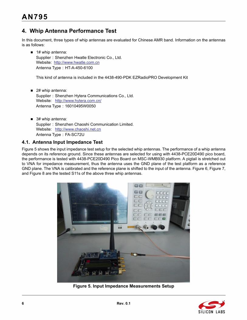
4.1. Antenna Input Impedance TestFigure 5 shows the input impedance test setup for the selected whip antennas. The performance of a whip antennadepends on its reference ground. Since these antennas are selected for using with 4438-PCE20D490 pico board,the performance is tested with 4438-PCE20D490 Pico Board on MSC-WMB930 platform. A pigtail is stretched outto VNA for impedance measurement, thus the antenna uses the GND plane of the test platform as a referenceGND plane. The VNA is calibrated and the reference plane is shifted to the input of the antenna. Figure 6, Figure 7,and Figure 8 are the tested S11s of the above three whip antennas.
Figure 5. Input Impedance Measurements Setup

AN795
Rev. 0.1 7
Figure 6. S11 of the 1# Antenna
Figure 7. S11 of the 2# Antenna

AN795
8 Rev. 0.1
Figure 8. S11 of the 3# Antenna
The antenna is considered well-matched to 50 if S11 is below –10 dB. For the results shown in Figures 6-8, theS11 of 1# and 3# antenna is very good in the whole frequency band. The S11 of antenna 2# at some frequencypoints is not good, but the antenna can be matched to 50 by using external match circuits. If the impedance isnot well-matched to the antenna input impedance, it will be lead to a higher VSWR and a reduced radiated powerfrom the antenna. Furthermore, the antenna could damage the PA as a result of not being well-matched; however,the RF output is very robust against high VSWR using the matching circuit provided on the 4438–PCE20D490picoboard. Refer to the Si4438 PCE20D490 schematics under the Tools tab at http://www.silabs.com/products/wireless/EZRadioPRO/Pages/Si4438.aspx. No damage has been seen by removing the antenna or terminating theoutput by a short.

AN795
Rev. 0.1 9
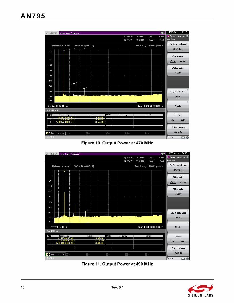
4.2. EIRP and Gain TestEIRP of the whip antenna were measured in an antenna chamber using the 4438-PCE20D490 Pico Board. Theoutput power of the pico board is set to be 17 dBm at 470 MHz, 490 MHz, and 510 MHz separately. The antenna isconnected on 4438-PCE20D490 via the SMA connector, which constructs the DUT. The spectrum analyzerrecords the EIRP while the DUT table is rotating 360°. Because the whip antenna has a vertical polarization, thepolarization of reference RX antenna is only set to vertical to get EIRP. Figure 9 shows the DUT with a coordinatesystem under the radiated measurements.
Figure 9. EIRP Test ChamberBefore measuring the EIRP and Harmonics, the RF performance of the pico board is measured with conductedway. The output power of 4438-PCE20D490 Pico Board is set to be 17 dBm at 470M, 490M and 510M separatelyaccording to Chinese AMR regulation. Three antennas are used to test EIRP and harmonics separately. Theconduct power is measured with an Anritsu MS2692 spectrum analyzer. Figure 10, Figure 11, and Figure 12 arethe conducted power measurements at 470 MHz, 490 MHz, and 510 MHz separately. From the results, theharmonics are well below their limits at different operating frequencies.
AN795
10 Rev. 0.1
Figure 10. Output Power at 470 MHz
Figure 11. Output Power at 490 MHz

AN795
Rev. 0.1 11
Figure 12. Output Power at 510 MHz
The EIRP and harmonic measurement of the whip antenna were measured in the antenna chamber. The 17 dBmoutput power from 4438-PCE20D490 Pico Board is injected to the antenna. The max radiated power andharmonics are recorded while the DUT antenna is rotating 360 degrees. Figures 13 to 21 are the measured results.

AN795
12 Rev. 0.1
Figure 13. EIRP and Harmonics of 1# Antenna at 470 MHz
Figure 14. EIRP and Harmonics of 1# Antenna at 490 MHz

AN795
Rev. 0.1 13
Figure 15. EIRP and Harmonics of 1# Antenna at 510 MHz
Figure 16. EIRP and Harmonics of 2# Antenna at 470 MHz

AN795
14 Rev. 0.1
Figure 17. EIRP and Harmonics of 2# Antenna at 490 MHz
Figure 18. EIRP and Harmonics of 2# Antenna at 510 MHz

AN795
Rev. 0.1 15
Figure 19. EIRP and Harmonics of 3# Antenna at 470 MHz
Figure 20. EIRP and Harmonics of 3# Antenna at 490 MHz

AN795
16 Rev. 0.1
Figure 21. EIRP and Harmonics of 3# Antenna at 510 MHzFrom the above results, all radiated harmonics are below their limits by at least 9 dB margin. In Chinese AMR bandregulation, the fundamental power is limited to 17 dBm ERP, which corresponds to 19.14 dBm EIRP. All of thefundamental radiation power is below the regulation limit.
The antenna gain can be calculated from the measured fundamental EIRP and the delivered power to the antenna(from conducted SA measurements). Calculated antenna gain = EIRP-17 dBm. The antenna gains for differentwhip antennas at different frequencies are shown in Table 1.
Table 1. Gains for Different Antenna Samples at Different Frequency
Antenna Sample
Gain at Different Frequency (dBi)
470 MHz 490 MHz 510 MHz
1# –3.36 –2.02 –3.23
2# –0.08 1.2 0.37
3# –0.99 –0.85 –0.55

AN795
Rev. 0.1 17
4.3. Range TestThe outdoor range is tested using two identical whip antennas on both TX and RX side. The output power at the TXside is set to its maximum. Data rate is set to 500 kbps, frequency deviation is set to250 kHz (GFSK, H=1), andcarrier frequency is set to 490 MHz. The sensitivity at RX side is –94 dBm (1e-3 BER at 500 kbps data rate and250 kHz deviation). The range is recorded with 1% packet error rate.
Figure 22. Range Test Sets

AN795
18 Rev. 0.1
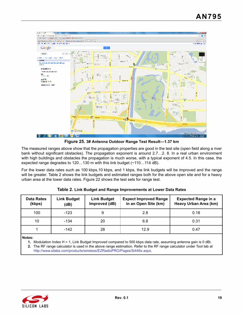
The range results are the values in [km] with Google map distance plot. The ranges are tested outside with500 kbps data rate. Figure 23, Figure 24, and Figure 25 are the range test results.
Figure 23. 1# Antenna Outdoor Range Test Result—1.29 km
Figure 24. 2# Antenna Outdoor Range Test Result—1.38 km
AN795
Rev. 0.1 19
Figure 25. 3# Antenna Outdoor Range Test Result—1.37 kmThe measured ranges above show that the propagation properties are good in the test site (open field along a riverbank without significant obstacles). The propagation exponent is around 2.7…2. 8. In a real urban environmentwith high buildings and obstacles the propagation is much worse, with a typical exponent of 4.5. In this case, theexpected range degrades to 120…130 m with this link budget (~110…114 dB).
For the lower data rates such as 100 kbps,10 kbps, and 1 kbps, the link budgets will be improved and the rangewill be greater. Table 2 shows the link budgets and estimated ranges both for the above open site and for a heavyurban area at the lower data rates. Figure 22 shows the test sets for range test.
Table 2. Link Budget and Range Improvements at Lower Data Rates
Data Rates(kbps)
Link Budget(dB)
Link Budget Improved (dB)
Expect Improved Range in an Open Site (km)
Expected Range in a Heavy Urban Area (km)
100 -123 9 2.8 0.18
10 -134 20 6.8 0.31
1 -142 28 12.9 0.47
Notes:1. Modulation Index H = 1, Link Budget Improved compared to 500 kbps data rate, assuming antenna gain is 0 dBi.2. The RF range calculator is used in the above range estimation. Refer to the RF range calculator under Tool tab at
http://www.silabs.com/products/wireless/EZRadioPRO/Pages/Si446x.aspx.

AN795
20 Rev. 0.1
4.4. Summary of Whip Antenna PerformanceBased on the range test results, the performance of these whip antennas are summarized in Table 3. The radiationpattern of the antennas is not measured in this document, and during range test the radiation pattern is notinvestigated or considered.
Table 3. Measured Whip Antenna Performance
Antenna Samples
Input Impedance or
S11(dB)
Gain(dBi) EIRP(dBm) Harmonics Margin to Limit(dB)
Range(km)
Price (USD) Need External Match
Circuits
1# Best(Below –10.3 in
whole bandwidth)
Low (–2.02 at 490MHz)
Low (14.98 at 490 MHz)
Good (above 12)
Good(1.29)
Medium(1.0)
NO
2# Acceptable(Below
–6.4 in whole bandwidth)
High (1.2 at 490 MHz)
High (18.20 at 490 MHz)
Good (above 11)
Good (1.38)
High(1.5)
Need L type match circuit
3# Good(Below –10.2 in
whole bandwidth)
Medium (–0.85 at 490 MHz)
Medium (16.15 at 490 MHz)
Good (above 9)
Good (1.37)
Low(0.9)
NO

http://www.silabs.com
Silicon Laboratories Inc.400 West Cesar ChavezAustin, TX 78701USA
Smart. Connected. Energy-Friendly.
Productswww.silabs.com/products
Qualitywww.silabs.com/quality
Support and Communitycommunity.silabs.com
DisclaimerSilicon Labs intends to provide customers with the latest, accurate, and in-depth documentation of all peripherals and modules available for system and software implementers using or intending to use the Silicon Labs products. Characterization data, available modules and peripherals, memory sizes and memory addresses refer to each specific device, and "Typical" parameters provided can and do vary in different applications. Application examples described herein are for illustrative purposes only. Silicon Labs reserves the right to make changes without further notice and limitation to product information, specifications, and descriptions herein, and does not give warranties as to the accuracy or completeness of the included information. Silicon Labs shall have no liability for the consequences of use of the information supplied herein. This document does not imply or express copyright licenses granted hereunder to design or fabricate any integrated circuits. The products are not designed or authorized to be used within any Life Support System without the specific written consent of Silicon Labs. A "Life Support System" is any product or system intended to support or sustain life and/or health, which, if it fails, can be reasonably expected to result in significant personal injury or death. Silicon Labs products are not designed or authorized for military applications. Silicon Labs products shall under no circumstances be used in weapons of mass destruction including (but not limited to) nuclear, biological or chemical weapons, or missiles capable of delivering such weapons.
Trademark InformationSilicon Laboratories Inc.® , Silicon Laboratories®, Silicon Labs®, SiLabs® and the Silicon Labs logo®, Bluegiga®, Bluegiga Logo®, Clockbuilder®, CMEMS®, DSPLL®, EFM®, EFM32®, EFR, Ember®, Energy Micro, Energy Micro logo and combinations thereof, "the world’s most energy friendly microcontrollers", Ember®, EZLink®, EZRadio®, EZRadioPRO®, Gecko®, ISOmodem®, Precision32®, ProSLIC®, Simplicity Studio®, SiPHY®, Telegesis, the Telegesis Logo®, USBXpress® and others are trademarks or registered trademarks of Silicon Labs. ARM, CORTEX, Cortex-M3 and THUMB are trademarks or registered trademarks of ARM Holdings. Keil is a registered trademark of ARM Limited. All other products or brand names mentioned herein are trademarks of their respective holders.