high voltage technology module (question and answer).docx
TRANSCRIPT
HIGH VOLTAGE TECHNOLOGY
QUESTION AND ANSWER
PREPARED BY
ASSOC. PROF. DR. ZOLKAFLE BIN BUNTAT
MAY 2013

CHAPTER 1
ELECTRIC FIELDS
(QUESTION & ANSWER)
Question 1
a. There are two types of field distribution, known as homogeneous and non-homogeneous
field. What are the differences of both field distributions? State the electrodes-gap
configuration to simulate the homogeneous and non-homogeneous field.
Answer:
i. Homogeneous field
E is the same throughout the field region.
Uniform or approximate uniform field distributions exists between two infinite
parallel plates, or 2 spheres of equal diameters with gap spacing < sphere
radius.
“Profiled” parallel plates of finite sizes are also used to simulate
homogeneous field.
ii. Nonhomogeneous field
E is different at different points in the field region.
In the absence of space charges, E usually obtains the maximum value at the
surface of the conductor which has the smallest radius of curvature –
nonhomogeneous and asymmetrical.
Most of the practical HV components have nonhomogeneous and
asymmetrical field distribution..
In some gaps – will produce nonhomogeneous fields and symmetrical, e.g.
rod-rod or sphere-sphere (large distance between spheres) gaps.
HV electrode has higher E than the grounded electrode.

b. Experimental analogue is one of the methods for determining the potential distribution.
Briefly describe any two of the experimental analogs used for space-charge-free fields.
Answer:
i. Electrolytic Tank
Widely used for decades.
Equipotential boundaries are represented in the tank by specially form sheets
of metal.
Example, a single dielectric problem such as a three-core cable may be
represented by electrolytes of different conductivities separated by special
partitions.
ii. Semiconducting Paper Analog
Less accurate but attractively simple alternative to the electrolyte.
Errors from this method result from the non-homogeneity of the paper
resistivity.
Errors also dependence on the ambient humidity and the contact resistance
to the electrodes.

iii. Resistive Mesh Analog
The continuous field is replacing by a discrete set of points as depicted by a
mesh of resistors.
The used of discrete resistors introduce an error arising from the finite mesh
analysis.
This error may be reduced by reducing the mesh size.
c. A high voltage DC transmission line rated at 132 kV peak traverses a location where a
road shall be constructed below it as shown in Figure Q1. The metallic walls L1 and L2
are energized at 20 kV peak and 80Kv respectively, and each standing on the insulator
made of polycarbonate. Use the Finite Difference Method to determine the potential at
point 2, 4 and 6. Limit the iteration process to two only.
Figure Q1
Answer:

1st iteration
V 1=132+0+0+204
=38kV
V 2=132+0+0+384
=42.5kV
V 3=132+80+0+42.54
=63.63 kV
V 4=38+0+0+204
=14.5kV
V 5=42.5+0+0+14.54
=14.25kV
V 6=63.63+80+0+14.254
=39.47 kV
2nd iteration
V 1=132+42.5+14.5+204
=52.25kV
V 2=132+63.63+14.25+52.254
=85.53 kV
V 3=132+80+39.47+65.534
=79.25kV
V 4=52.25+14.25+0+204
=21.63kV
V 5=65.53+39.47+0+21.634
=31.66kV
V 6=79.25+80+0+31.664
=47.73kV
The potential at point 2, 4 and 6 after 2 iterations are;
V2 = 65.53 kV, V4 = 21.63 kV, V6 = 47.73 kV

Question 2
a. Briefly describe any two (2) of the followings:
i. Field enhancement factor
ii. ‘Medium High Voltage’ (MHV), ‘High voltage’ (HV), ‘Extra high Voltage’ (EHV)
and ‘Ultra high voltage’ (UHV)
iii. Three applications of high voltages excluding those in the generation,
transmission and distribution of electrical energy
Answer:
i. Whereas any designer of the high voltage apparatus must have a complete
knowledge of the electric field distribution, for a user of the system the knowledge
of the maximum value of the electric field
Emaxto which the insulation is likely to be subjected and the location of such
maximum gradient point is generally sufficient. Consequently, the concept of
field enhancement factor or simply field factor f is of considerable use. This
factor is defined as
f=EmaxEav
( for homogenousdieletric medium)
Where Eavthe average is field in the gap and is equal to the applied potential/gap
separation between the electrodes
Emax=f .V /d
Field utilization factor μ f=1f
(larger μ f represents a more compact equipment)

ii. The following voltage classification describes the meanings:
Voltage class Voltage range
Medium high voltage (MHV) 1kV<V=<70kV
High Voltage (HV) 110kV<V=<230kV
Extra high voltage (EHV) 275 kV<V=<800kV
Ultra high voltage (UHV) 1000kV=<V
iii. Any three of the followings:
ESPs for the removal of dust from flue gases
Atomization of liquids, paint spraying and pesticide spraying
Ozone generation for water and sewage treatment
X-ray generators and particles accelerators
High power lasers and ion beams
Plasma sources for semiconductor manufacture
Superconducting magnet coils
b. There are several properties of a dielectric which are of practical importance for an
engineer. Name five (5) most important properties of a dielectric and briefly describe
each of them.
Answer:
Any five of the followings:
i. DC conductivity
σ= JE=1
ρ
Dependent on material purity, T and E
σ (T )=Ae− EkT
Due to polarization effects, σ also depends upon time of application of the
stress

ii. Dielectric permittivity
εr=C /Co
Dependent on T, f and molecular structure of the insulating material
iii. Complex permittivity
Parallel RC model R represents the lossy part (electronic and ionic conductivity, dipole orientation and space charge polarization, etc.) capacitance in the presence of the dielectric I= jωCoV (εr− jεr tan δ)= jωCoVε∗
ℜ=εr
ℑ=εrtanδωCV 2tanδ
tanδ=σ /ωεoεr
iv. Loss angle
See (iii)
v. Dissipation factor
Similar to tan delta
vi. Polarization
Most electron are bound
Electrostatic forces create some level of polarization forming dipoles
It is this electronic polarization which results in relative permittivity of more
than 1 for most dielectric materials
Atomic polarization
Organic substances, e.g. Polymers
Interfacial polarization
vii. Dielectric strength
The maximum value of applied electric field at which a dielectric material is stressed in a homogenous(hence uniform?) field electrode system, breaks down and loses its insulating property

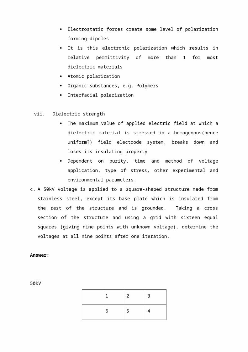
Dependent on purity, time and method of voltage application, type of stress, other experimental and environmental parameters.c. A 50kV voltage is applied to a square-shaped structure made from stainless steel,
except its base plate which is insulated from the rest of the structure and is grounded.
Taking a cross section of the structure and using a grid with sixteen equal squares
(giving nine points with unknown voltage), determine the voltages at all nine points after
one iteration.
Answer:
50kV
1 2 3
6 5 4
7 8 9
0kV
V 1=50+50+0+04
=25.00 kV
V 2=25+50+0+04
=18.75kV
V 3=50+50+18.75+04
=29.69kV
50kV 50kV

V 4=29.69+50+0+04
=19.92kV
V 5=18.75+19.92+0+04
=9.67kV
V 6=25+50+9.67+04
=21.17kV
V 7=21.17+50+0+04
=17.79kV
V 8=9.67+17.79+0+04
=6.87kV
V 9=19.92+6.87+50+04
=19.20kV
Node 1st iteration (kV)
1 25.00
2 18.75
3 29.69
4 19.92
5 9.67
6 21.17
7 17.79
8 6.87
9 19.20
QUESTION 3
a. The build-up of high currents in a gas breakdown is due to the process of ionization in
which electrons and ions are created from neutral atom or molecules. Explain how the
ionization process occurs prior to gas breakdown phenomena.
ANSWER:
When a high voltage is applied between the two electrodes immersed in a gaseous
medium, the gas becomes a conductor and an electrical breakdown occurs. The
process that responsible for the breakdown of a gas is called ionization. This process
initially liberates an electron from a gas molecule with the simultaneous production of a
positive ion. The generations of new electrons are from ionization by collision, photo-
ionization and the secondary ionization process. Under high voltage stress, a few of the
electrons produced at the cathode due to the certain process will produce positive ions
and additional electrons. The process repeats itself and hence increases in the electron
current.
b. In an experiment using certain gas, it was found that a steady state current of 600 µA
flowed through the plane electrode separated by a distance of 0.5 cm when a voltage of
10 kV is applied. Determine the Townsend’s first iteration coefficient if a current of 60 µA
flow when the distance of separation is reduced to 0.1 cm and the field is kept constant
at the previous value.
If the breakdown occurred when the gap distance was increased to 0.9 cm, what is the
value of Townsend’s secondary ionization coefficient?
ANSWER:
Since the field is kept constant (i.e., if distance of separation is reduced, the voltage is
also reduced by the same ratio so that V/d is kept constant)
I=I o eαx
Substituting two different set of values:
600=I oe0.5α and 60=I0 e0.1α
=> 10=e0.4α

Therefore, α =5.76 ionizing collisions/cm
The breakdown criterion is given by:
1−γ (eαx−1 )=0
Therefore the Townsend’s secondary ionization for the breakdown to be occurred at gap
distance 0.9 cm is:
γ (eαx−1 )=1
γ= 1
(e¿¿ αx−1)=1
(e¿¿ (5.76 )(0.9)−1)=1
177.4¿¿
¿5.64 x 10⁻¹ cm−1
c. In SF6 gas, the effective ionization coefficient is given by:
αp
= 27.7[ Ep ] – 2460
Where α is the effective ionization coefficient incm−1, E is the electric field strength in
kV/cm and p is the pressure (referred to 20 °C) in bar. Breakdown may be predicted
using streamer criterion∫0
d
α .dx=18, where d is the length of the electrodes gap in cm.
Estimate the length of a uniform field gap that will just hold off a steady voltage of 100 kV
in SF6 at 4 bar and 60 °C.
ANSWER:
Given
αp=27.7
Ep−2460
Therefore,
α=27.7 E – 2460 p;
Multiply both sides with d , gives
αd=27.7 Ed−2460 pd

¿27.7V−2460 pd
pd=27.7V−αd2460
(1)
Given; ∫0
d
αdx=18 ;=¿αd=18(2)
The normalized pressure of 4 bar at 60°C is;
pn=40001013
.293
273+60=3.47 ¿
From (1) and (2);
d=27.7V−αd2460 pn
=27.7 (100 )−18
2460(3.47)=0.32cm

QUESTION 4
a. Describe briefly the reasons for electric stress being considered as the main contributor
to the breakdown of insulation. The description should be based on the principle of
insulation breakdown.
ANSWER:
Breakdown criteria for gas:
γ (eαx−1 )=1
Since αp=f ( E
p )∧γ=g (Ep)
Then at breakdown, α ds=pds f (E s
p )=p ds f (V s
pd)
» g( V s
pds)¿
The ionization of gases is related to
αp=f ( E
p )
I.e. α is dependent on E which is electric field. The rate of gas ionization is
dependent on the energy and velocity of free electrons, whereas electron energy and
velocity are dependent on the electric field applied to gas medium.

b. Describe briefly the element of electric stress optimization in the case where a solid
cylindrical insulator is sandwiched between a circular electrode and ground as shown in
Fig. Q4b. The description should put more emphasis on the tangential field distribution
and method to achieve it.
Figure Q4 b)
ANSWER:
The cylindrical shape insulator sandwiched between the plane electrode and ground
will experience non-optimized tangential field considering it from ground plane.
Whereas, with an insulator of profile shown in Fig. 1(b) with dotted line will provide
optimized field distribution.
c. Use the iteration method to find the finite difference approximation to the potential points
1, 2, 3 and 8 of the Fig.Q4c (Limit the iteration up to 2 only). The nodal voltage follows
the sequence as shown in Fig.Q4c that is the node number is 1,2,3,4,5,6,7 and 8
respectively where R₁ = 10 kΩ, R₂ = 30 kΩ, R₃= 20 kΩ, R₄ = 10 kΩ, Eₐ = 400V and EB =
600V
Figure Q4.c)
ANSWER:
V aa=R1
R1−R2
.Ea=10kΩ
(10−30)kΩ.400=100V
V bb=R3
R3−R4
. Eb=10kΩ
(10−20)kΩ.600=200V
Iteration 1:
V 1=100+200+0+0
4=75V
V 2=200+75+0+0
4=68.8V
V 3=200+200+0+68.8
4=117.2V

V 4=100+100+0+0
4=50V
V 5=75+0+0+50
4=31.3V
V 6=68.8+0+31.3+0
4=25V
V 7=117.2+0+25+0
4=35.5V
V 8=200+200+35.5+0
4=108.9V
Iteration 2:
V 1=100+200+68.8+31.3
4=100V
V 2=200+117.2+25+100
4=110.6V
V 3=200+200+35.5+110.6
4=136.5V
V 4=100+31.3+0+100
4=57.8V
V 5=100+25+57.8+0
4=45.7V
V 6=110.6+35.5+0+45.7
4=48.4V
V 7=136.5+108.9+0+48
4=73.4V
V 8=200+200+73.4+0
4=118.4 V
Therefore:
V 1=100V ,V 2=110.6V ,V 3=136.5V ,V 8=118.4 V


QUESTION 5
a. State the most useful equation which can be used directly to solve electric field problem
using Finite Difference Method?
ANSWER:
V o=14[V 1+V 2+V 3+V 4 ]
Where V 1+V 0 , V 2+V 0 , V 3+0 , V 4+V 0 are equidistance .
b. State the differences between electrostatic field and electromagnetic field?
ANSWER:
Electrostatic field Electric Field
i) Static charge i) Time varying current
ii) Coulomb’s Law ii) Maxwell’s Law

c. A high voltage DC transmission line rated at 132 kV peak traverses a location where a
road shall be constructed below as shown in Fig.Q5. The metallic walls L1 and L2 are
respectively energized at 20 kV peak and each standing on an insulator made of
polycarbonate, Use the Finite Difference Method to determine the potential value of point
5. Imaginary meshes are constructed below the transmission line each of size 10 meters
by 10 meters. Determine the potential at point 4 if the metallic wall L1 is shorted to the
ground. Limit the iteration process to 2 only.
Fig Q5.(c)
ANSWER:
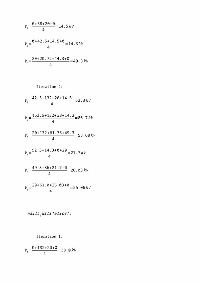
Iteration 1:
V 1=0+132+20+0
4=38.0kV
V 2=0+132+38+0
4=42.5kV
V 3=20+132+42.5+0
4=48.63kV
V 4=0+38+20+0
4=14.5kV
V 5=0+42.5+14.5+0
4=14.3 kV

V 6=20+20.72+14.3+0
4=49.3kV
Iteration 2:
V 1'=42.5+132+20+14.5
4=52.3kV
V 2'=162.6+132+38+14.3
4=86.7kV
V 3'=20+132+61.78+49.3
4=58.68kV
V 4' =52.3+14.3+0+20
4=21.7 kV
V 5'=49.3+86+21.7+0
4=26.03kV
V 6'=20+61.0+26.03+0
4=26.06 kV
∴Wall L1 will falloff .
Iteration 1:
V 1=0+132+20+0
4=38.0kV
V 2=0+33+0+132
4=41.3kV
V 3=20+132+41.3+0
4=48.3kV
V 4=0+38+20+0
4=14.5kV
V 5=0+33+0+0
4=8.3 kV

V 6=20+48.3+12.4+0
4=20.2kV
Iteration 2:
V 1'=41.3+132+0+8.3
4=45.4kV
V 2'=43.3+132+45.4+12.4
4=59.5kV
V 3'=20+132+59.5+20.2
4=58.0 kV
V 4' =12.4+45.4+0+0
4=14.5kV
V 5'=20.2+59.5+14.5+0
4=23.6kV
V 6'=20+58.0+23.6+0
4=25.4 kV

Question 6
a. Give two advantages for the provision of the electric field stress control in high voltage
equipment.
ANSWER:
i. Insulation life is adversely affected by an increase in the operating stress values.
ii. Increase the efficiency of HV equipment.
iii. Can understand the failure mechanisms. The knowledge of electric field within
the insulation is essential since it is the intensity of electric field that determines
the onset of breakdown in dielectrics.
iv. The clearances of various HV components can only be determined if the
insulation behaviour under various stress as well as the field distributions within
the components are known.
b. Briefly describe the use of high voltage system in the following applications:
i. Removing industrial flue gases or dust particles floating in air from steel mill
chimneys
ii. Spraying pesticide to agriculture plantation
ANSWER:
i. By applying high voltage power supply to the electrode, corona activity will take
place creating ion pairs, which some ions will be positively charge will stick to the
flue gases or particles. Then passage towards the coherent cause some of them
to be drawn to collecting electrode.
ii. Due to the intense field at the tip of the nozzle, the emitting droplets of pesticide
are broken down to smaller and almost equal sizes. Thus, in affect increase the
coulombs force acting on the tiny droplets of spray and make it higher than
gravitational and inertial forces. This electrically changed force union of pesticide
has high attraction towards the leaves of the plants and ensures safeness.
Average on both sides of the leaves.
c. Use the iteration method to find the finite difference approximation to the potentials at
points 1, 2, 3, 9 and 15 of the system in Figure Q1. The nodal voltage follows the
sequence as shown in Figure Q1 that is node number is 1, 2, 3, 4, 5, 6, 7 up to 16
respectively.
Figure Q1
ANSWER:
The potential on 1, 5, 6, 12, 13, 14, 15, 16, and 17 are as follows.
Node Number Potential (V)
1 100
5 200
6 200
12 100
13 0
14 0
15 0
16 0
17 0
Potential to be estimated are 2, 3, 4, 7, 8, 9, 10, 11.
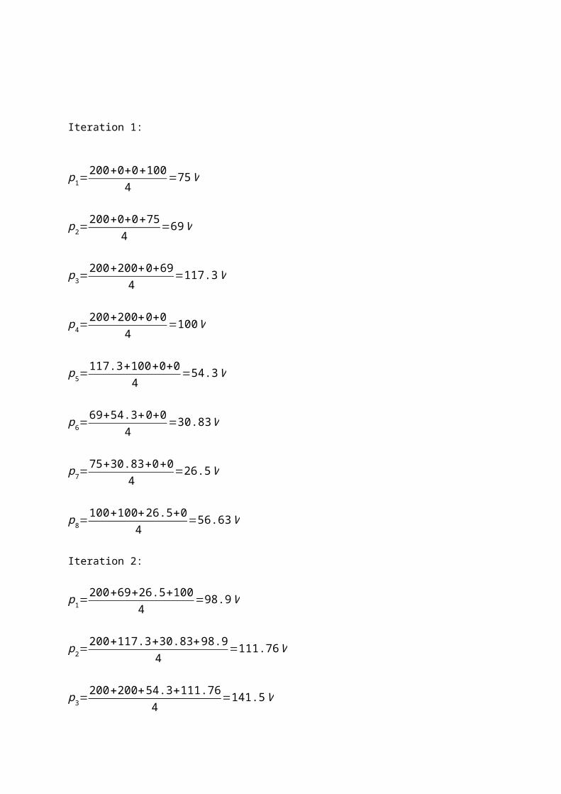
Iteration 1:

p1=200+0+0+100
4=75V
p2=200+0+0+75
4=69V
p3=200+200+0+69
4=117.3V
p4=200+200+0+0
4=100V
p5=117.3+100+0+0
4=54.3V
p6=69+54.3+0+0
4=30.83V
p7=75+30.83+0+0
4=26.5V
p8=100+100+26.5+0
4=56.63V
Iteration 2:
p1=200+69+26.5+100
4=98.9V
p2=200+117.3+30.83+98.9
4=111.76 V
p3=200+200+54.3+111.76
4=141.5V
p4=200+200+0+54.3
4=113.8 V
p5=141.5+113.8+0+30.82
4=71.53V
p6=111.76+71.53+0+26.5
4=52.4V

p7=98.9+52.4+0+56.63
4=52V
p8=100+52+0+100
4=63V
So: Potential at 1 = 100 VPotential at 2 = 98.90 VPotential at 3 = 111.76 VPotential at 9 = 52.4 VPotential at 15 = 0 V

QUESTION 7
a. Give three reasons for finding the electric field distribution in high equipment.
ANSWER:
Insulation life is adversely affected by an increase in the ooperating stress
values.
Increase the efficiency of HV equipment.
Can understand the failure mechanisms. The knowledge of electric field within the
insulation is essential since it is the intensity of electric field that determines the onset of
breakdown in dielectrics
b. Define the basic field equations
i. If there is no space charge in the dielectric medium
ii. If there is space charge in the dielectric medium
ANSWER:
i. ∇ .E= ρε
E=−∇V
∇ 2V=− ρε
ii. ∇ .E= ρε
E=−∇V
∇ 2V=− ρε

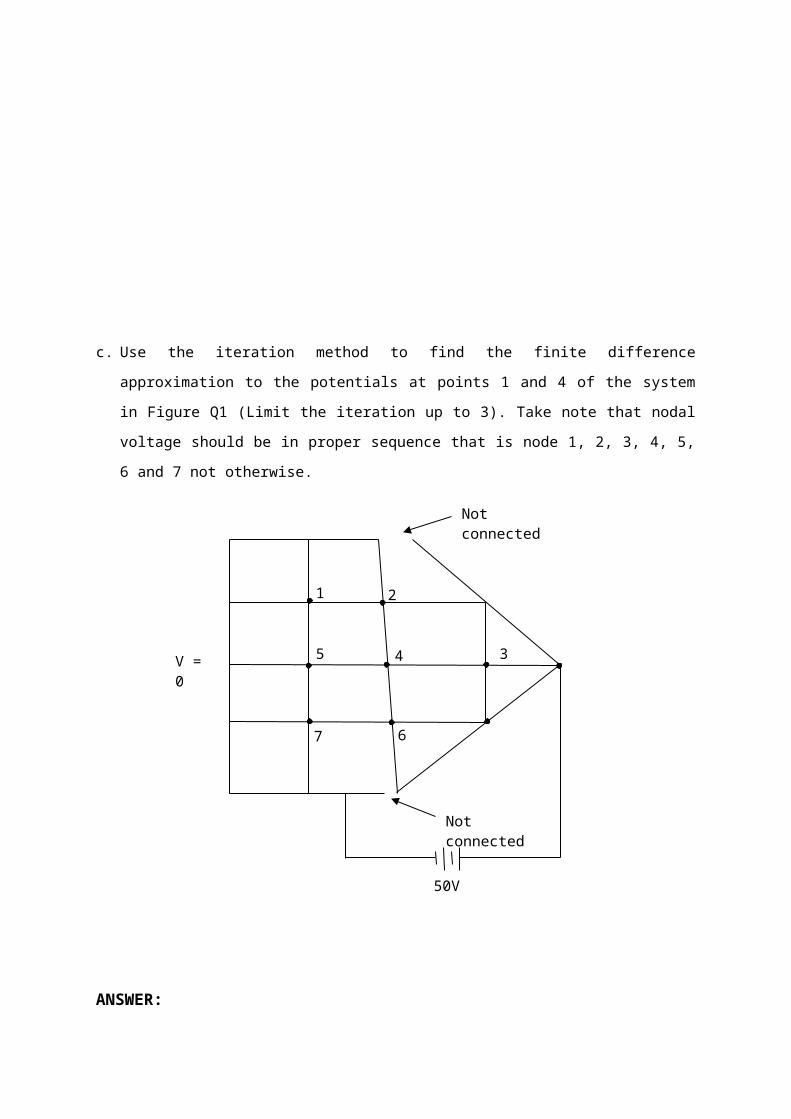
c. Use the iteration method to find the finite difference approximation to the potentials at
points 1 and 4 of the system in Figure Q1 (Limit the iteration up to 3). Take note that
nodal voltage should be in proper sequence that is node 1, 2, 3, 4, 5, 6 and 7 not
otherwise.
ANSWER:
Iteration 1
For node 1:
V 1=0+0+0+0
4=0V
For node 2:
V 2=0+0+50+0
4=12.5V
7 6
5 4 3
21
V = 0
50V
Not connected
Not connected

For node 3:
V 3=0+50+50+50
4=37.5V
For node 4:
V 4=0+12.5+37.5+0
4=12.5V
For node 5:
V 5=0+0+12.5+0
4=3.13V
For node 6:
V 6=0+12.5+50+50
4=28.1V
For node 7:
V 7=0+3.13+28.1+0
4=7.8V
Iteration 2
V 1=0+0+12.5+0
4=3.13V
V 2=3.9+0+50+12.5
4=16.9V
V 3=12.5+50+50+50
4=40.62V
V 4=3.13+16.6+40.63+28.1
4=22.12V
V 5=0+3.9+22.12+7.8
4=8.44V
V 6=7.8+22.12+50+50
4=32.5V
V 7=0+8.46+32.5+0
4=10.24 V
Iteration 3:
V 1=0+0+16.6+8.46
4=6.27V
V 2=6.27+0+50+22.12
4=19.6V
V 3=22.12+50+50+50
4=12.5V
V 4=8.46+19.6+43.03+32.5
4=25.9V
V 5=0+6.27+25.9+10.24
4=10.6V
V 6=10.24+25.9+50+50
4=34.04V

V 7=0+10.6+34+0
4=11.15V
Summary of node potential
V 1=6.27 ,3.13 ,0
V 2=19.6 ,16.9 ,12.5
V 3=12.5 , 40.62,37.5
V 4=25.9 ,22.12 ,12.5
V 5=10.6 ,8.44 ,3.13
V 6=34.04 ,32.5 ,28.1
V 7=11.15 ,10.24 ,7.8

CHAPTER 1
INTRODUCTION TO
HIGH VOLTAGE TECHNOLOGY
(QUESTION AND ANSWER)

QUESTION 1
a. There are two type of field distribution, known as homogeneous and non-
homogeneous field. What are differences of both field distributions? State the
electrodes-gap configuration to simulate the homogeneous and non-homogeneous
field.
ANSWER:
Homogeneous field:
E is the same throughout the field region.
Uniform or approximate uniform field distributions exist between 2 infinite parallel
plates, or 2 spheres of equal diameters with gap spacing < sphere radius.
“Profiled” parallel plates of finite sizes are also used to simulate homogeneous
fields.
Non-homogeneous field:
E is different at different points in the field region.
In the absence of space charges, E usually obtains the maximum value at the
surface of the conductor which has the smallest radius of curvature non-
homogeneous and asymmetrical.
Most of the practical HV components have non-homogeneous and asymmetrical
field distribution.
In some gaps – will produce non-homogeneous fields and symmetrical, e.g. rod-
rod or sphere-sphere (large distance between spheres) gaps.
HV electrode has higher E than the grounded electrode.
b. Experimental analog is one of the methods for determining the potential distribution.
Briefly describe any two of the experimental analogs used for space-charge-free
fields.
ANSWER:
1. Electrolytic Tank
Widely used for decades.
Equipotential boundaries are represented in the tank by specially formed
sheets of metal.
Example, a single dielectric problem such as a three-core cable may be
represented by electrolytes of different conductivities separated by special
partitions.
Fig: Electrolytic tank model of a three-core cable represented at the
instant when one core is at zero voltage, the same as the sheath
2. Semiconducting Paper Analog
Less accurate but attractively simple alternative to the electrolyte.

Errors in this method result from the nonhomogeneity of the paper
resistivity.
Errors also dependence on the ambient humidity and the contact
resistance to the electrodes.
Fig: Field plot between two spheres with skanks,
as plotted by a semiconducting paper model
3. Resistive-Mesh Analog
The continuous field is replaced by a discrete set of points as depicted by
a mesh of resistors.
The used of discrete resistors introduce an error arising from the finite
mesh analysis.
This error may be reduced by reducing the mesh size.
Fig: Resistive mesh analog of the field pattern
between two electrodes.
The potential at node 0;
V 0− (V 1+V 2+V 3+V 4 )÷ 4

Due to discretization, simulation of electrostatic fields in the vicinity of
curved surfaces of the electrodes is bound to be of reduced accuracy.
c. A high voltage DC transmission line rated at 132 kV peak traverses a location where
a road shall be constructed below it as shown in figure Q1. The metallic walls L1 and
L2 are energized at 20 kV peak and 80 kV respectively, and each standing on the
insulator made of polycarbonate. Use the Finite Difference Method to determine the
potential at point 2, 4 and 6. Limit the iteration process to two only.
Power line
12 3
4 5 6
Figure Q1
ANSWER:
1st iteration
V 1=132+0+0+204
=38kV
V 2=132+0+0+384
=42.5kV
V 3=132+80+0+42.54
=63.63kV
V 4=38+0+0+204
=14.5kV
V 5=42.5+0+0+14.54
=14.25kV
V 6=63.63+80+0+14.254
=39.47
L1
L2
Ground

2nd iteration
V 1=132+42.5+14.5+204
=52.25kV
V 2=132+38+63.63+14.254
=61.97 kV
V 3=132+80+39.47+65.534
=79.25kV
V 4=52.25+14.25+0+204
=21.63kV
V 5=65.53+39.47+0+21.634
=31.66kV
V 6=79.25+80+0+31.664
=47.73kV
The potential at point 2, 4 and 6 after 2 iterations are;
V2 = 61.97 kV, V4 = 21.63 kV, V6 = 47.73 kV

QUESTION 2
a. Describe briefly, with the aid of suitable diagrams, equations and/or examples, where
appropriate, the avalanche process in the breakdown phenomenon of gaseous
dielectrics.
ANSWER:
The avalanche process is one of the processes which occur in the breakdown of
gaseous dielectrics and is based on the generation of successive ionizing collisions
leading to an avalanche. Suppose a free electron exists (caused by some external
effect such as radio-activity or cosmic radiation) in a gas where an electric field
exists. If the field strength is sufficiently high, then it is likely ionize a gas molecule by
simple collision resulting in 2 free electrons and a positive ion. These 2 electrons will
be able to cause further ionization by collision leading in general to 4 electrons and 3
positive ions. The process is cumulative, and the number of free electrons will go on
increasing as they continue to move under the action of the electric field. The swarm
of electrons and positive ions produced in this way is called an electron avalanche. In
the space of a few millimeters, it may grow until it contains many millions of
electrons.

b. Show that the breakdown criterion in gas according to Paschen’s Law is given by:
g (V s / pds ) exp [ pds . f (V s/ pds ) ]−1 =1
where,
ds – gap distance at sparkover voltage
p – pressure
Vs – sparkover voltage
F & g – different functions
ANSWER:
By neglecting attachment, breakdown criterion
γ (ead−1 )=1 ………….. (1)
Since (Paschen’s Law), α / p=f (E / p ) and γ=g (E/ p), where f∧g significant
different function.
At breakdown, α ds=pdf (E s/ p )
¿ pds f (V s/ pds ) ………. (2)
And γ=g (E s/ p )=g (V s/ pds) ……… (3)
Substitute (2) & (3) into (1) gives;
g (V s / pds ) exp [ pds . f (V s/ pds ) ]−1 =1
c. The following data are given for two parallel while the electric field stress, E is kept
constant.
i. I = 1.2I0 when d = 0.5 cm
ii. I = 1.6I0 when d = 1.3 cm
iii. I = 2.3I0 when d = 2 cm

Where I0 is the initial current and d is distance between the plates.
Find the values of the Townsend Primary and Secondary coefficients, α and γ
ANSWER:
Using equation, I=I oeαd
For d = 0.5 cm, 1.2 I o=I o e0.5α∨α 1d 1=ln1.2=0.182α 1=0.38 /cm
For d = 1.3 cm, 1.6 I o=I oe1.3α∨α 2d2=ln 1.6=0.47α 1=0.36 /cm
For d = 2 cm, 2.3 I o=I oe2α∨α 3 d3=ln 2.3=0.83α 1=0.42 /cm (This suggests
that for this gap γ starts to be active).
The value of γ can be found from the equation;
I=Ioexp (αd)
1−γ [exp (αd )−¿1 ]¿
2.3= e (2 ×0.36 )
1−γ (e0.72−1)= 2.0544
1−1.0554 γ
γ=0.101/cm
QUESTION 3
a. Briefly describe any two (2) of the followings:
i. Field enhancement factor:
ii. ‘Medium high Voltage’ (MHV), ‘High Voltage’ (HV), ‘Extra High Voltage’ (EHV)
and ‘Ultra High Voltage’ (UHV)
iii. Three applications of high voltages excluding those in the generation,
transmission and distribution of electrical energy
ANSWER
i. Whereas any designer of the high voltage apparatus must have a complete
knowledge of the electric field distribution, for a user of the system the knowledge
of the maximum value of the electric field Emax to which the insulation is likely to

be subjected and the location of such a maximum gradient point is generally
sufficient. Consequently, the concept of field enhancement factor or simply field
factor (f) is of considerable use. This factor I defined as
F= E maxE av
(for homogeneous dielectric medium)
Where E av is the average field in the gap and is equal to the applied
potential/gap separation between the electrodes.
E max = f.Vd
Field utilization factor µf = 1f
(larger µf represents a more compact equipment)
ii. The following voltage classification describes the meanings:
Voltage Class Voltage Range
Medium high voltage (MHV) 1kV < V =< 70 kV
High Voltage (HV) 110kV < V =< 230 kV
Extra high voltage (EHV) 275kV < V =< 800 kV
Ultra high voltage (UHV) 1000kV =< V
iii. Any three of the followings:
i. ESPs for the removal of dust from flue gases
ii. Atomization of liquids, paint spraying and pesticide spraying
iii. Ozone generation for water and sewage treatment
iv. X-ray generators and particle accelerators
v. High-power lasers and ion beams
vi. Plasma sources for semiconductor manufacture
vii. Superconducting magnet coils.

b. There are several properties of dielectric which are of practical importance for an
engineer. Name five (5) most important properties of a dielectric and briefly describe
each of them
ANSWER
i. DC conductivity
σ= JE=1
ρ
dependent on material purity,T and E
σ (T )=Ae –EkT
due to polarization effects, σ also depends upon time of application of the
stress
ii. Dielectric permittivity
ε r= CC o
Dependent on T , f and molecular structure of the insulating material
iii. Complex permittivity
Parallel RC model
R represents the lossy part (electronic and ionic conductivity, dipole
orientation and space charge polarization, etc. Capacitance in the
presence of the dielectric

I= jωC ˳V (εᵣ− jεᵣ tan δ)= jωC ˳Vε
Rₑ=ε ᵣ
ℑ=εᵣ tan δ ωCV 2 tan δ
tan δ is dependent on f , E∧¿ T
Power loss = ωC ˳V 2 εᵣ tan δ
tan δ=¿σ /ωε ˳εᵣ¿
iv. Loss angle
see (iii)
v. Dissipation factor
Similar to tan δ
vi. Polarization
Most electrons are bound
Electrostatic forces create some level of polarization forming dipoles
It is this electronic polarization which results in relative permittivity of
more than 1 for most dielectric materials.
Atomic polarization
Organic substances, e.g. Polymers
Interfacial polarization
vii. Dielectric strength

The maximum value of applied electric field at which a dielectric material
is stressed in a homogeneous (hence uniform) field electrode system,
breakdown and loses its insulating property
Dependent on purity, time and method of voltage application, type of
stress, other experimental an environmental parameters.
c. A 50 kV AC voltage is applied to a square-shaped structure made from stainless
steel, except its base plate which is insulated from the rest of the structure and is
grounded. Taking a cross section of the structure and using a grid with sixteen equal
squares (giving nine points with unknown voltage), determine the voltages at all nine
points after one iteration
50kV
1 2 3
65 4
7 8 9
0kV
V 1=50+50+0+04
=25.00 kV
V 2=25+50+0+04
=18.75kV
V 3=50+50+18.75+04
=29.69kV
V 4=29.69+50+0+04
=19.92kV
50kV
50kV

V 5=18.75+19.92+0+04
=9.67kV
V 6=25+50+9.67+04
=21.17kV
V 7=21.17+50+0+04
=17.79kV
V 8=9.67+17.79+0+04
=6.87kV
V 9=19.92+6.87+50+04
=19.20kV
Node 1st iteration (kV)
1 25.00
2 18.75
3 29.69
4 19.92
5 9.67
6 21.17
7 17.79
8 6.87
9 19.20
QUESTION 4
a. The build-up of high current in a breakdown is due to the process of ionization in
which electrons and ions are created from neutral atoms or molecules. Explain how
the ionization process occurs prior to gas breakdown phenomena.
ANSWER:
When a high voltage is applied between the two electrodes immersed in a gaseous
medium, the gas becomes a conductor and an electrical breakdown occurs. The
process that responsible for the breakdown of a gas is called ionization. This process
initially liberates an electron from a gas molecule with the simultaneous production of
a positive ion.
The generations of new electrons are from ionization by collision, photo-ionization
and the secondary ionization process. Under high voltage stress, a few of the
electrons produced at the cathode due to the certain process will produce positive
ions and additional electrons. The process repeats itself and hence increases in the
electron current.
b. The ionization coefficient α/p as function of field strength E and gas pressure p is
given by the following threshold equation:
(αp )= fˌ( Ep )
By using the Townsend’s breakdown criterion, show that the breakdown voltage for
uniform field gaps is a function of gap length (d) and gas pressure (p).
ANSWER:
(αp )= fˌ( Ep ) (i)
The Townsend’s breakdown criterion;
γ [exp (αd)−1]=1 (ii)
Substituting (i) Into (ii);
ef (Ep ) pd ¿ 1
Y+1 (iii)

Taking in on both sides of (iii)
f [ Ep ] pd=ln [ 1Y+1]=K (vi)
For uniform field;
E=V b ¿d
Therefore,
ƒ¿b ¿ pd ] ¿K (v)
Or
ƒ¿b ¿ pd¿=K / pd ; V b ¿F (p .d )
Equation (vi) shows that the breakdown voltage of a uniform field gap is a unique
function of the product of gas pressure and the gap length for a particular gas and
electrode material. This relation is known as Paschen’s Law.
c. Fig.Q2 shows the experimental set-up for studying the Townsend discharge. The
experiment is conducted by measuring the current I at the different gap distance, d.
Table Q2 gives the set of observation obtained when studying the conduction and
breakdown in a gas.
i. Determine the initial current, I0.
ii. Calculate the value of the Townsend’s primary and secondary ionization
coefficients.
Table Q2 Townsend’s experimental data
Gap distance, d (mm) 1 2 3 4 5 6 8 10 12 14 16
Current I (pA) 19 21 26 32 40 45 80 106 152 255 430

Fig.Q2 Townsend’s experimental set-up
ANSWER
Gap distance, d (mm)
1 2 3 4 5 6 8 10 12 14 16
Current I (pA) 19 21 26 32 40 45 80 106 152 255 430
In I 2.94 3.043.26
3.47 3.69 3.81 4.38 4.665.02
5.54 6.06
I=I ˳ead
Taking In on both sides of (1);
ln I=ln ead+ ln I ˳
ln I=αd+ln I ˳ , y=mx+c
i. Plot graph ( ln I ) versus (d );

Gap dis-
tance, d
(mm)
1 2 3 4 5 6 8 10 12 14 160
1
2
3
4
5
6
7
2.94 3.04 3.26 3.47 3.69 3.814.38
4.665.02
5.546.06
In I
From the graph, interception © at ln I axis, gives;
(12-4=8) (5-3.5=1.5)
ln I ˳≈ 2.7 , I ˳≈ 14.88 pA
ii) Townsend’s primary ionization coefficient, α ;
Gradient of the graph (m) shows the value of α.
α ≈1.5÷ 8≈ 0.188mmˉˡ
Townsend’s secondary ionization coefficient,
I= I ˳ eαd
1−γ [eαd−1]
Substituting for higher value of;
430= 14.88 e(0.188 ) (16)
1– γ [ e(0.188 ) (16) –1 ]
¿ 301.271−19.25 γ

γ=0.016mmˉˡ
QUESTION 5
The build-up of high currents in a gas breakdown is due to the process of ionization in which
electrons and ions are created from neutral atoms or molecules. Explain how the ionization
process occurs prior to gas breakdown phenomena.
ANSWER:
When a high voltage is applied between the two electrodes immersed in a gaseous medium,
the gases becomes a conductor and an electrical breakdown occurs. The process that
responsible for the breakdown of a gas is called ionization. This process initially liberates
electron from a gas molecule with the simultaneous production of a positive ion. The
generations of new electrons are from ionization by collision, photo-ionization and the
secondary ionization process. Under high voltage stress, a few of the electrons produced at
the cathode due to the certain process will produce positive ions and additional electrons.
The process repeats itself and hence increases in the electron current.
QUESTION 6
In an experiment using a certain gas, it was found that a steady state current of 600µA
flowed through the plane electrode separated by a distance of 0.5cm when a voltage of 10kV
is applied. Determine the Townsend’s first ionization coefficient if a current of 60µA flows
when the distance of separation is reduced to 0.1cm and the field is kept constant at the
previous value.
If the breakdown occurred when the gap distance was increased to 0.9cm, what is the value
of Townsend’s secondary ionization coefficient?
ANSWER:
Since the field is kept constant (i.e., if distance of separation is reduced, the voltage is also
reduced by the same ratio so that Vd
is kept constant)
I=I o eαx

Substituting two different sets of values;
600=I oe0.5α (1) and 60=I oe
0.1α (2)
(1) ÷ (2)
600
60=
I o e0.5α
I o e0.1α
10=e0.4α ∴ α= 5.76 ionizing collisions/cm
The breakdown criterion is given by;
1−γ (eαx−1 )=0
Therefore the Townsend’s secondary ionization for the breakdown to be occurred at gap
distance 0.9cm is;
γ (eαx−1 )=1
γ= 1
(e¿¿ αx−1)=1
(e¿¿5.76(0.9)−1)=1
177.4¿¿
¿5.64 x 10⁻³ cm−1
QUESTION 7
In SF6 gas, the effective ionization coefficient is given by;
αp=27.7[ Ep ]−2460
Where α is the effective ionization coefficient in cm-1, E is the electric field strength in kV/cm
and p is the pressure (referred to 20 °C) in bar. Breakdown may be predicted using streamer
criterion, ∫0
d
α .dx=18, where d is the length of the electrodes gap in cm. Estimate the length
of a uniform – field gap that will just hold off a steady voltage of 100 kV SF6 at 4 bar and 60
°C.
ANSWER:

αp=27.7[ Ep ]−2460
α=27.7E-2460 p ; αd=27.7 Ed−2460 pd=27.7−2460 pd ;
pd=27.7V−αd2460
(1)
Given;∫0
d
αdx=18 ; αd=18 (2)
The normalized pressure of 4 bar at 60 °C is;
pn=40001013
.293
273+60=3.47 ¿
∴ From (1) and (2)
d=27.7V−αd2460 pn
.=27.7 (100 )−18
2460(3.47)=0.32cm
QUESTION 8
Use the iteration method to find the finite difference approximation to the potentials at points
1,2,3,9 and 15 of the system in figure Q2(c). (Limit the iteration up to 2 only). The nodal
voltage follows the sequence as shown in figure Q2(c) that is node number is 1,2,3,4,5,6,7
up to 16 respectively.

FIGURE Q2 (c)
ANSWER:
The general formula:
V n=V 1+V 2+V 3+V 4
4
Iteration 1
P1 P2 P3
P4P5P6P7P8

P 1=V 2=200+0+0+100
4=75V
P 2=V 3=200+0+0+75
4=68.75V
P 3=V 4=200+200+0+68.75
4=117.2V
P 4=V 7=200+200+0+0
4=100V
P 5=V 8=117.2+100+0+0
4=54.3V
P 6=V 9=68.75+54.3+0+0
4=30.76V
P 7=V 10=75+30.76+0+0
4=26.44 V
P 8=V 11=100+26.44+0+100
4=56.61V
Iteration 2:
P 1=V 2=200+68.75+26.44+100
4=98.8V
P 2=V 3=200+117.2+30.76+98.8
4=111.7 V
P 3=V 4=200+200+54.3+111.7
4=141.5V
P 4=V 7=200+200+0+54.3
4=113.6V

P 5=V 8=141.5+113.6+0+30.70
4=67.97V
P 6=V 9=111.7+67.97+26.44+0
4=51.53V
P 7=V 10=98.8+51.53+0+56.61
4=51.7V
P 8=V 11=100+51.7+0+100
4=62.92V
V 1=100V
P 1=V 2=98.8V
P 2=V 3=111.7 V
P 6=V 9=51.53V
V 15=0V
QUESTION 9

Describe the reasons for electric stress being considered as the main contributor to the
breakdown of insulation. The description should be based on the principle of insulation
breakdown.
ANSWER:
Breakdown criteria of gas
γ (eαx−1 )=1
αp=f [ Ep ]∧γ=g [ Ep ]
Then at breakdown, α ds=pds f [ E s
p ]=pds f [ V s
pd ]
∴g [ V s
pds](e pds f [ V s
pd ]−1)=1
The ionization of gases is related to
αp=f [ Ep ]
i.e. α is dependent on E which is electric field. The rate of gas ionization is dependent on
the energy and velocity of free electrons, whereas electron energy and velocity are
dependent on the electric field applied to the gas medium.

QUESTION 10
Describe briefly the elements of electric stress optimization in the case where a solid
cylindrical insulator is sandwiched between a circular electrode and ground as shown in Fig.
Q1b. The description should put more emphasis on the tangential field distribution and
method to achieve it.
ANSWER:
The cylindrical shape insulator sandwiched between the plane electrode and ground will
experience non-optimized tangential field considering it from ground plane. Whereas, with an
insulator of profile shown in Fig. 1(b) with dotted line will provide optimized field distribution.
QUESTION 11
Optimized profile
Nonoptimized
Distance Z (cm)
0
30
25
20
15
10
8642
Optimized
Nonoptimize

Use the iteration method to find the finite difference approximation to the potential at points
1, 2, 3 and 8 of the system in Fig.Q1c (Limit the iteration up to 2 only). The nodal voltage
follows the sequence as shown in Fig.Q1c that is the node number 1, 2, 3, 4, 5, 6, 7 and 8
respectively where R1 = 10KΩ, R2 = 30KΩ, R3 = 20KΩ, R4=10KΩ, Ea = 400V , Eb = 600V.
ANSWER:
V aa=R1
R1+R2
. Ea=10 K Ω
10 K Ω+30 K Ω.400=100V
Vaa
Vbb

V bb=R4
R4+R3
. Ea=10 K Ω
10 K Ω+20 K Ω.600=200V
Iteration 1
V 1=100+200+0+0
4=75V
V 2=200+75+0+0
4=68.8V
V 3=200+200+0+68.8
4=117.2V
V 4=100+100+0+0
4=50V
V 5=75+0+0+50
4=31.3V
V 6=68.8+0+31.3+0
4=25V
V 7=117.2+0+25+0
4=35.5V
V 8=200+200+35.5+0
4=108.9V
Iteration 2:

V 1=100+200+68.8+31.3
4=100.0V
V 2=200+117.2+25+100
4=110.6V
V 3=200+200+35.5+110.6
4=136.5V
V 4=100+31.3+0+100
4=57.8V
V 5=100+25+57.8+0
4=45.7V
V 6=110.6+35.5+0+26.44+0
4=45.7V
V 7=136.5+108.9+0+48
4=73.4V
V 8=200+200+73.4+100
4=118.4 V
V 1=100V
V 2=110.6 V
V 3=136.5V
V 8=118.4V

QUESTION 12
a. Show that in the process of gas breakdown, the Townsend First Ionization
Coefficient, α is given by;
α=1d
ln [ I t
I o]
where,
d- gap distance
I t- total current
I o- initial current
ANSWER:
Total no. of electron at anode, n(d)=no eαd. At steady state, average current in gap
at distance x,
I−¿(x)= Io eαx ¿ and I +¿(x)=I o(e¿¿αd−eαx)¿¿
Total number of current, I t=I−¿( x)+ I+¿(x) ¿¿ ¿ I o eαd
I t
I o
=eαd
αd=ln [ It
I o]
∴α= 1d
ln [ I t
I o]

b. The following data in table Q12b are given for two parallel plates while the electric
field, E is kept constant.
Table Q12b
Gap distance, d(cm) Ratio of Current and Initial Current, II o
0.5 1.2
1.3 1.6
2.0 2.3
ANSWER:
By using equation, I ¿ I o eαd
For d = 0.5 cm, 1.2 I o=I o e0.5α
or α 1 d1 ln 1.2=0.182 ,∴α1=0.36 /cm
For d = 1.3 cm, 1.6 I o=I o e1.3 α
or α 2 d2 ln 1.6=0.47 ,∴α 2=0.36 /cm
For d = 2 cm, 2.3 I o=I o e2α
or α 3 d3 ln2.3=0.83 ,
∴α3=0.42/cm (This suggest that for this gap γ start to be active)
The value of γ can be found from the equation;
II o
= eαd
1−γ (eαd−1)
2.3= e(2x 0.36)
1−γ (e0.72−1)= 2.0544
1−1.0544 γ
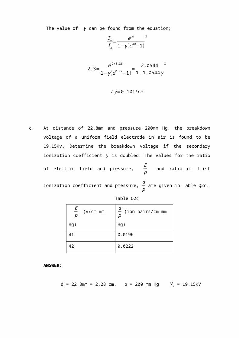
∴ γ=0.101/cm

c. At distance of 22.8mm and pressure 200mm Hg, the breakdown voltage of a uniform
field electrode in air is found to be 19.15Kv. Determine the breakdown voltage if the
secondary ionization coefficient γ is doubled. The values for the ratio of electric field
and pressure, Ep
and ratio of first ionization coefficient and pressure, αp
are given in
Table Q2c.
Table Q2c
Ep
(v/cm mm Hg)αp
(ion pairs/cm mm Hg)
41 0.0196
42 0.0222
ANSWER:
d = 22.8mm = 2.28 cm, p = 200 mm Hg V s = 19.15KV
Ep
= 42 v/cm mm Hg, αp
= 0.0222
Ep
= 41 v/cm mm Hg, αp
= 0.0196
Find V s when γ is doubled?
From secondary Townsend Breakdown Process,
I=I o eαd
1−γ (eαd−1)
and E = V s
d
Breakdown criteria: 1−γ (eαd−1 )=0 or γ eαd=1
E = V s
d =19.15
2.28 = 8.40 KV/cm = 8400V/cm

Ep=8400
200 = 42 v/cm mm Hg
From table;
αp
= 0.0222 ∴ α = 0.0222(200) = 4.44
∴αd=4.44 x2.28=10.12
From breakdown criteria (is doubled, α α ' ),
∴ γ eαd=2 γ eα 'd=1
eαd
eα' d=2
¿ - α ' ) = ln 2
α - α ' = ln22.28
∴α '=4.14
α '
p=4.14
200=0.02068
By Interpolation;
0
αp
0.02222
0.02068
0.0196
Ep42
2
Ep
41

Ep=41+
(0.02068−0.0196)(0.0222−0.0196)
=41.42
∴E=41.42 (200 )=8284 v/cm
∴V s=Ed=8284 x 2.28=18.89 Kv
QUESTION 13
a. State the most useful equation which can be used directly to solve electric field
problem using Finite Difference Method?
ANSWER:
V o=14[V 1+V 2+V 3+V 4 ]
Where V 1+V 0 , V 2+V 0 , V 3+0 , V 4+V 0 are equidistance .
b. State the differences between electrostatic field and electromagnet field?
ANSWER:
Electrostatic Field Electromagnet
a) Static Field a) Time Varying current
b) Coulomb’s Law b) Maxwell’s Law

c. A High Voltage DC transmission line rated at 132 kV peak traverses a location where
a road shall constructed below it as shown in Fig.1. The metallic walls L1 and L2 are
respectively energized at 20kV peak and each standing on an insulator made of
polycarbonate. Use the Finite Difference Method to determine transmission line each
of size 10 meters by 10 meters. Determine the potential at point 4 if metallic wall L1 is
shorted to the ground. Limit the iteration process to 2 only. Fig.1 The general
arrangement of a transmission power line traversing a piece of land.
Fig.1
ANSWER :
Iteration 1:
V 1=0+132+20+0
4=38.0kV
V 2=0+132+38.0+0
4=42.5kV

V 3=20+132+42.5+0
4=48.63kV
V 4=0+38+20+0
4=14.5kV
V 5=0+42.5+14.5+0
4=14.25 kV
V 6=20+48.63+14.25+0
4=20.72kV
Iteration 2:
V 1'=42.5+132+20+14.5
4=52.25kV
V 2'=52.25+132+48.63+14.25
4=61.78kV
V 3'=20+132+61.78+20.72
4=58.63 kV
V 4' =52.25+14.25+0+20
4=21.13 kV
V 5'=61.78+21.13+20.72+0
4=25.91kV
V 6'=20+58.63+25.91+0
4=26.14 kV

∴Wall L1 will falloff .
Iteration 1:
V 1=0+132+0+0
4=33.0kV
V 2=132+33+0+0
4=41.25kV
V 3=132+41.25+20+0
4=48.31kV
V 4=33+0+0+0
4=8.25kV
V 5=41.25+8.25+0+0
4=12.38kV
V 6=48.31+12.38+20+0
4=20.17 kV
Iteration 2:
V 1'=132+0+41.25+8.25
4=45.38kV
V 2'=132+45.38+48.31+12.38
4=59.49kV

V 3'=132+59.49+20+20.17
4=57.92kV
V 4' =45.38+0+12.38+0
4=14.44kV
V 5'=59.49+14.44+20.17+0
4=23.53 kV
V 6'=57.92+23.53+20+0
4=25.36kV
QUESTION 14
Discuss with suitable diagrams the mechanisms which lead to breakdown in liquid insulation.
ANSWER:
Suspended Particle Mechanism
1. Impurities present as fibers or dispersed solid particles
2. Electrostatic force acting on impurities
3. Solid impurities – force directed towards maximum stress
4. Gas impurities – force directed towards areas of lower stress
5. Form a stable chain bridging the gap.
Cavitations & Bubble Mechanism
1. Breakdown strength depends on applied hydrostatic pressure
2. Formation of vapor bubble responsible for breakdown due to
- Gas pockets at electrodes surface
- Electrostatic repulsive forces
3. Gases products by electron collision
4. Vaporization of liquid by corona at sharp points and surface irregularities.
Thermal Mechanism

1. Breakdown under pulse condition
2. High density current pulses give rise to localized heating and formed bubbles
3. Breakdown occurs due to elongation of bubbles to critical size and bridge the gap
4. Breakdown strength depends on pressure and liquid molecular structure.
Stressed Oil Volume Mechanism
1. Breakdown strength is determined by largest possible impurity or weak link.
2. Breakdown strength is inversely proportional to the stressed oil volume
3. Breakdown voltage influence by gas content in the oil, viscosity and the presence of
impurities.
QUESTION 15
Show the breakdown criterion in gas according to Paschen’s Law is given by
g (V s / pds ) exp [ pds . f (V s/ pds ) ]−1 =1
Where,
d s - gap distance at sparkover voltage
p - pressure
V s - sparkover voltage
f∧g - different function
ANSWER:
By neglecting attachment, breakdown criterion
γ (ead−1 )=1 ………….. (1)
Since (Paschen’s Law), α / p=f (E / p ) and γ=g (E/ p), where f∧g significant different
function.
At breakdown, α ds=pdf (E s/ p )
¿ pds f (V s/ pds ) ………. (2)

And γ=g (E s/ p )=g (V s/ pds) ……… (3)
Substitute (2) & (3) into (1) gives;
g (V s / pds ) exp [ pds . f (V s/ pds ) ]−1 =1
QUESTION 16
Breakdown voltage measurement of a uniform field gap in air at 32930 K gave the following
results shown in Table Q16.
Table Q16
pd (bar-cm) E/p at breakdown (kV bar¯¹ cm¯¹)
1.0 30.30
9.0 26.00
Determine the breakdown voltage of a 20 mm gap at a pressure of 3 bars and
temperature of 3000 K .
ANSWER:
V s=Apd+B (pd )12
Ed=Apd+B (pd )12
E=Ap+B ( p/d )12
E / p=A+B/ ( pd )12
From the data given,

30.3=A+B / (1 )12
30.3=A+B …………. (1)
26.0¿ A+B/ (9 )12
26.0=A+0.33 B ………. (2)
From (1) and (2); A=23.55 and B =6.42
For the case of atmospheric air;
V s=23.88 (p /d )+6.42 (p /d )12
p=3 , t=300 K ,d=2cm ,V s=?
QUESTION 17
a. Give two advantages for the provision of the electric field stress control in high voltage
equipment.
ANSWER
Increase the efficiency of high voltage equipment
Insulation life is adversely affected by an increase in the operation stress return.
b. Briefly describe the use of high voltage system in the following application:
i) Removing industrial flue gases or dust particles floating in air from steel mill
chimneys
ANSWER:
By applying high voltage power supply to the electrode, corona activity will
take place creating ion. Some ion will be positively changed which stick to
the gas or particles.
ii) Spraying pesticide to agriculture plantation

ANSWER:
Due to Incense field at the tip of the nozzle the emitting of one particle
broken down to smaller and almost equal sizes.
iii)

c. Use the iteration method to find the finite difference approximate to the potentials at
point 1, 2, 3, 9, and 15 of the system in Fig. Q1 (limit the iteration up to 2 only). The
nodal voltage follows the sequence as shown in Fig. Q1 that is node number is 1, 2,
3, 4, 5, 6, 7 up to 16 respectively.
Figure Q1
ANSWER:
Iteration 1:
p1=100V
p2=200+0+0+100
4=75V
p3=200+0+0+75
4=68.75V
p4=200+200+0+68.75
4=117.19V
p7=200+200+0+0
4=100V

p8=117.19+100+0+0
4=54.29V
p9=68.75+54.29+0+0
4=30.76V
p10=75+0+0+30.76
4=26.44V
p11=100+100+0+26.44
4=56.61V
p15=0V
Iteration 2:
p1=100V
p2=200+100+68.75+26.44
4=98.79V
p3=200+98.79+30.76+117.19
4=111.69 V
p4=200+111.69+54.29+200
4=141.49V
p7=200+54.29+0+200
4=113.57V
p8=141.49+30.76+0+113.57
4=71.45V
p9=11.69+26.44+0+71.45
4=52.39V
p10=98.79+56.61+0+52.39
4=51.95V
p11=100+100+0+51.95
4=62.99 V
p15=0V
Therefore: p1=100V , p2=98.79V , p3=111.69V , p9=52.39V , p15=0V
QUESTION 18
Discuss the processes that lead to ion-generation in a gas breakdown.
ANSWER:
i. Ionization by Electron Impact
Ionization by Electron Impact is the most important process for gas discharge. Kinetic
energy exchanged during collision. Gas atom or molecule becomes excited or ionized
by the energy acquired from the incident atom. Portion of kinetic energy prior to impact
converted to potential energy. Atom or molecule may be ionized by a subsequent with
another slow-moving election.
ii. Photoionization
Result of external radiations. Eg. Cosmic rays, X-rays, Nuclear radiations. Continuous
process produces ions and electrons. It’s capable of penetrating most conventional
walls. It’s also an easy method to produce spark or to ignite combustible mixture with
free electrons. Insulation of high-voltage systems at high attitude is subjected to reduce
air density and increase in ionization by cosmic rays.
iii. Electron Detachment
Electron detached from negative ions in the gas. It’s requires large concentration of
negative ions. Eg. Gas discharged under impulse voltages.
A−h∪⇔ A+e−¿

QUESTION 19
In an experiment to determine the breakdown properties of air, the uniform field electrode is
used. The breakdown process occurs in accordance with Townsend First and Second
Ionization coefficient, α and γ .
At a distance of 22.8 mm and pressure 200 mm Hg, the breakdown voltage is found to be
19.5 kV. Determine the breakdown voltage if the secondary ionization coefficient γ is
doubled. Data’s for the ratio of electric field and pressure, Ep
and ration of first ionization
coefficient, αp
are given in the Table Q19.
Table Q19
Ep
(V/cm mm Hg)αp
(ion pairs/cm mm Hg)
41 0.0196
42 0.0222
ANSWER:
d=22.8mm=22.28cm , p=200mm. Hg ,V s=19.15kV
Ep=42
Vcm
.mm.Hg ;αp=0.0222
Ep=42
Vcm
.mm.Hg ;αp=0.0196
Find V swhen γ is double?
From secondary Townsend Breakdown Process,
I=I o eαd
1−γ [eαd−1]∧E=
V s
d
Breakdown criteria:

1−γ [eαd−1 ]=0∨γ eαd=1
I=V s
d=19.15
2.28=8.4
kVcm=8400
Vm
Ep=8400
200=42
Vcm
.mm.Hg
From Table:
αp=0.00222 , α=0.0222 (200 )=4.44 , αd=4.44 x2.28=10.12
From breakdown criteria (γ is double, α →α ' )
γ eαd=γ eα' d=1
eαd
eα' d=2
(α−α ' )d=ln2
(α−α ' )d= ln22.28
α '=4.14
α 'p=4.14
200=0.02068
By interpolation
Ep=41+
(0.02068−0.0196)0.0222−0.0196
=41.42
E=41.42(200)=8284Vcm
V s=Ed=8284 x 2.28=18.89kV
QUESTION 20
a. Give three reasons for finding the electric field distribution in high voltage equipment.
ANSWER:
1. The use of high voltage in electric power transmission to avoid excessive line
currents which would render the transmission system uneconomical.
2. High voltage is utilized is based on the fact that bodies charged under high
voltage develop an electrostatic force. Applications: cathode-ray tubes,

particle accelerators, xerography, spray painting, and electrostatic
precipitators.
3. High-voltage presence makes use of the ability of high voltage to initiate
ionization in dielectric materials where energy is subsequently released in
controlled quantities. Applications: e.g., ignition in internal combustion
engines, gas-discharge lamps, and ozone generation.
b. Define the basic field equation:-
i) If there is no space charge in the dielectric medium.
ii) If there is space charge in the dielectric medium.
ANSWER:
i) Using the Laplace’s equation if there is no space charge in the dielectric
medium.
∇2V=0
ii) Using Poisson’s equation if the medium has a space charge density.
∇ .∇V=∇2 V
¿−PE0
c. Use the iteration method to find the finite diffence approximation to the potentials at
point 1 and 4 of the system in fig. Q1 (limit the iteration up to 3 only). Take node that
nodal voltage should be in proper sequence that is node 1, 2, 3, 4, 5, 6 and 7 not
otherwise.

ANSWER:
Iteration 1:
V 1=0+0+0+0
4=0V
V 2=0+0+50+0
4=12.5V
V 3=0+50+50+50
4=37.5V
V 4=10+12.5+37.5+0
4=12.5V
V 5=0+0+12.5+0
4=3.13V

V 6=0+12.5+50+50
4=28.1V
V 7=0+3.13+28.1+0
4=7.8V
Iteration 2:
V 1=0+0+12.5+3.13
4=3.9V
V 2=3.9+0+50+12.5
4=16.6V
V 3=12.5+50+50+50
4=40.62V
V 4=3.12+16.6+40.63+28.1
4=22.12V
V 5=0+3.9+22.12+7.8
4=8.46V
V 6=7.8+22.12+50+50
4=32.5V
V 7=0+8.46+32.5+0
4=10.24 V

Iteration 3 :
V 1=0+0+16.6+8.46
4=6.27V
V 2=6.27+0+50+22.12
4=19.6V
V 3=22.12+50+50+50
4=43.03V
V 4=8.46+19.6+43.03+32.5
4=25.9V
V 5=0+6.27+25.9+10.24
4=25.9V
V 6=10.24+25.9+50+50
4=34.04V
V 7=0+10.6+34+0
4=11.15V
Therefore:
V 1=6.27V ,V 4=25.9V
QUESTION 21

a. Describe the secondary process which can follow an electron avalanches and how
these process may be identified. Show that discharge current in a multi avalanche
Townsend process in a non-attaching gas is given by
I = I 0 exp(αd)
1−γ [exp (αd−1 )]
ANSWER:
The electrical breakdown of a gas is brought about by various processes of
ionization. These are gas processes involving the collision of electrons, ions and
photons with gas molecules and electrode processes which take place at or near the
electrode surface. When a pair of electrodes is immersed in a gas and a voltage
applied across them, the current – voltage characteristic of figure below is observed.
At low voltage the observed current is due to collection of free charge carriers in the
gap and as the voltage is increased a level is reach at which the free electrons gain
enough energy to ionize. Electrons produced may cause further ionization so that an
electron avalanche is generated. Ionization is the process by which an electron
removed from an atom, leaving the atom with a net positive charge. The probability of
ionization due to the electrons will depend on the number of collisions made per unit
distance with coefficient α. α is referred as the primary ionization coefficient which is
number of ionizing collisions per electrons per cm travel.
With the primary ionization alone the discharged is not self – sustaining. If the source
of initial electrons is removed, the current I fall to zero. This suggests that processes
other than the simple α- process are occurring. The additional current is produced by

secondary emission processes. A secondary ionization coefficient γ is defined as the
number of secondary electrons produced at the cathode per electron produced in the
gap.
These processes for secondary – electron liberation can be identified by;
i) Positive – ion , γ i – ions do not have enough energy to ionize gas molecules directly
but may release electrons on colliding with the cathode surface.
ii) Photon, γ p – a proportion of the collisions in the gap cause excitation of neutral –
gas molecules which on return to the ground state may emit photons which release
electrons by photoemission.
iii) Metastables, γ m – metastable molecules may diffuse to the cathode and release
electrons.
One or more secondary mechanism may exist giving a total secondary effect
describe by
γ = γ i + γ p + γ m
Let no = the number of initial electrons at cathode
n 0 ‘ = the number of initial secondary
no “ = the total emission including secondary
i.e no “ = no + no ‘
At x, n(x) = no “ exp(αx)

The total number of new electrons produced, n(d) = no “¿].
If γ electrons are produced at the cathode per ionizing collision in the gap, then
n0 ‘ = γn0” ¿]
Thus , no “ = no + γn0” ¿]
no “ = n0
1−γ [exp (αd−1 )]
Therefore n(d) = no “ exp(αd) = n0exp (αd)
1−γ [exp (αd−1 )]
Under steady state conditions , I = I 0 exp (αd)
1−γ [exp (αd−1 )]
b. What is meant by ‘time lag to breakdown’ and describe how it may be influenced and
exploited.
ANSWER:
On the application of a voltage, a certain time elapses before actual breakdown
occurs even though the applied voltage may be much more than sufficient to cause
breakdown. In considering the time lag observed between the application of a voltage
sufficient to cause breakdown and the actual breakdown, the two basic processes of
concern are the appearance of avalanche initiating electrons and the temporal
growth of current after the criterion for static breakdown is satisfied.
In time – resolved studies. A step function voltage pulse is applied to the gap. The
time to breakdown then comprises;
i) Statistical time lag, ts elapsing prior to the appearance of an electron to initiate the
primary avalanche.
ii) Formative time lag’, tf required for the current builds up by secondary processes.
Analysis of formative time lags can yield information on the relative contributions of
the various secondary processes. The shortest formative times would be expected
with the photon secondary mechanism when the secondary cathode photoelectrons

are produced during the avalanche – crossing time. In general the formative time lag
is a function of the pulse amplitude, pressure and gap spacing.
c. Describe with diagrams the principle breakdown mechanisms which can occur in
solid dielectrics and identify their order of occurrence on a stress-time diagram.
ANSWER:
In almost all electrical equipment, solid insulating materials are used to separate
conductors at different potentials. Failure of the insulation occurs if a conducting or
partially conducting path is established between these conductors. This can occur
either over the surface of the insulating materials or through the body of the material.
When the discharge part occurs across the surface of the material, this is known as
“surface tracking” or “surface flashover”. When breakdown occurs through the body
of the insulating materials, the damage is totally irreparable and the insulation must
be replaced.
It is generally accepted that there are seven ways in which solid insulation can:
1) Electrochemical failure
2) Discharges in cavities within the insulation
3) Breakdown in initiated by spark penetration
4) Electromechanical failure
5) Ambience discharges

6) Thermal breakdown
7) Intrinsic breakdown
The order of the occurrence of the above mechanism can be illustrated on a stress-time
diagram as below.
1) Electrochemical breakdown
In electrical component design for use at low voltage and frequencies, electrochemical
damage is more probable than other types of failure. The deterioration is cause by irons
liberated at the electrodes by conducting current. The damage is dependent both on the
current and reaction with the insulating material. The effect can always be reduced by
reducing the leakage current.
2) Discharges in cavities
Solid insulating material often contains small cavity of gas in which the applied stress is
considerably greater than in the solid material. This can be understood by considering
the equivalent circuit shown below.
If as is almost inevitable, the stress in the gas phase exceeds the breakdown stress for
the gas, then partial breakdown will take place within the cavity this causes thermal and
chemical degradation of the solid dielectric around the boundaries of the cavity and over
a period of time this can lead to a failure of the dielectric.
3) Breakdown initiated by spark penetration on ambient discharge
In practice, the electrodes are never perfectly embedded in the solid insulation and the
dielectric is stressed in conjunction with one or more materials. If one of these materials
has a lower dielectric strength than the solid dielectric then the measured breakdown
voltage will be influence more by that weak medium than by the solid.
A local breakdown of the dielectric at the tips of the discharge is therefore likely and
complete breakdown is the result of such breakdown channels formed in the solid.
4) Electromechanical failure

This types of failure is more applicable to less rigid forms of insulating materials such as
rubber, pvc etc. if we consider two electrodes supported apart by an elasticity material
and a voltage is applied , an attracting electrostatic force will be established between the
plates. This will cause them to move together against the natural elasticity of the
dielectric material because the plates move together, the electrostatic force between
them increases and this will caused a further reduction in spacing. At a certain applied
voltage Vs, an unstable situation will be set up and dielectric material will be collapsed.
5) Thermal breakdown
When a field applied to a dielectric at room temperature the conduction current is
normally very low but its value increases rapidly with temperature. Correspondingly as
current increases so the heat generated within the dielectric increases the temperature
rises further. As the temperature of the dielectric increases, thermal dissipation from its
surface occurs and the final resulting temperature depends upon the heat dissipated in
relation to the heat generated.
6) Intrinsic breakdown
It is considered to be the breakdown mechanisms which take place in the absences of all
other no mechanism know of failure. Intrinsic breakdown theories generally involve
electronic process and it was natural in view of the success of Townsend avalanche
theory in gasses.

QUESTION 22
Measurement of breakdown voltages in a uniform-field spark gap in air gave the results as
shown in Table below
Gap spacing
(mm)Pressure (Bar)
Temperature
(°C)
Breakdown
Voltage, Vs
(kV)
2.5 1.03 30 0.91
27 1.185 15 88.38
Using the expression derived from Paschen’s law, Vs=A (pd )+B (√ pd ), determine;
i. The relative air density ρ referred to standard atmospheric conditions of 1013
25 mbar and 20°C.
ANSWER:
d=0 .25cm , ρ=1034 mbar , t=30° C,Vs =0 .90kV
d=2.7cm , ρ=1180mbar , t=15° C,Vs=88 .56kV
ρ20=10341013
⋅273+20273+30
=10341018
⋅293303
=0.99
ρ20=11801013
⋅298288

ii. The value of constants A and B
ANSWER:
V ll g/m3=V 9+V 9⋅¿ ¿∆V
=V 9(1+∆V )
=0.90 [1+0 .002(2) ]=0.91kV
V ll g/m3=V 12(1−∆V )
=88. 56 [1−0 . 002(1) ]=88. 38kV
V s1=Aρ1d1+B√ ρ1d1
V s2=Aρ2d2+B√ ρ2 d2 ________ χ
=1 .21
ρ1d1=0 .99(0 .25)=0 .25
√ ρ1d1=0 .5
ρ2 d2=1 .21(2 .7)=3 .27
√ ρ2d2=1 .81Dari _______ χ0 .91=A (0.25 )+B (0.5 )________ 188 .38=A (3 .27 )+B (1 .81) ______2
[88 .380 .91 ]=[3 .27 1 .81
0 .25 0 .5 ][ AB ]A=[88 . 38 1 . 81
0 . 91 0 . 53 . 27 1 . 810 . 25 0 . 5
]

B=[ 3 . 27 88 .380 . 25 0 . 913 . 27 1 .810 . 25 0 .5
]
iii. The breakdown voltage of a 3 cm gap spacing at a pressure of 3000 mbar and a
temperature of 20°C.
ANSWER:
d=3cm, ρ=3000mbar,t=20 °C
√ ρd=2 .98
∴V s=35. 75(8 . 88 )−16 . 07(2 .98 )
=88. 38(0 .5)−1. 81(0 .91)3 .27(0 . 5)−1.81(0 . 25)
=44 .19−1 .651 .64−0 .45
=42. 541 .19=35 . 75
=3 .27(0 .91)−88 .38 (0.25 )1 .19
=2 .98−22.101 .19=−16 .07
ρ20=30001013
×293293
=2 .96
ρd=2 .96(3 )=8 .88
=317 . 46−47 .89=269 . 57kV

QUESTION 23
a. In a strongly in homogeneous field, external partial discharges occur at electrodes of
small radius of curvature when a definite voltage is exceeded. These are referred to
as corona discharges and depending upon the voltage amplitude, they result in a
larger number of charge pulses of very short duration. With the aid of the diagram
where appropriate,
i. Define the terms corona
ANSWER:
The term corona is used to describe the discharge phenomena which occur at
highly – stressed electrodes prior to the complete breakdown of the gap
between the electrodes. It is a partial discharge in air around a sharp point or
thin wire in a strong, non-uniform field. It is characterized by a visible glow, an
audible noise, radio interference, chemical effect such as production of ozone
and loss of electrical power. It occurs whenever the local voltage gradient
exceeds the ionization value of the air and depends on the air density,
humidity and in outdoor situations whether it is fair weather or raining and
also on the roughness of the conductor surface.
ii. Types of corona and how it occurs
ANSWER:
Corona can be classified into;
1) DC Corona
a) Positive corona(anode)
When the highly-stressed electrode is the anode, the following corona
modes are observed as the voltage is increased.
Onset streamers

Also known as ‘burst’ pulses, these are intermittent, filamentary
discharges which propagates only a short distance from the highly-
stressed electrodes.
Hermstein glow
As the voltage increased, the intermittent streamer discharges give
way to a steady glow discharges. This transition occurs when a large
enough negative – iron space is generated near the anode to give a
quasi-uniform field in that region.
Breakdown streamers
Eventually, the shielding effect of the glow discharge is not able to
prevent the formation of large streamers which propagate well into the
gap.
b) Negative corona (cathode)
When the highly-stressed electrode is negative, three modes are
again observed.
Trichel pulses
These differ from the burst pulses in that their magnitude and
repetition frequency are both very regular.
Cathode glow
As the voltage is raised a critical Trichel pulses repetition frequency is
reached and the repetitive discharge is replaced by a steady cathode
glow.
Negative streamers
These discharges are usually known as negative feathers to avoid
confusion with positive streamers discharges. They develop out of the
glow mode and a long rise time compared with other pulsating
coronas.

2) AC corona
With an alternating voltage applied, the same basic corona types will
appear although their characteristic maybe altered to an extent which
depends on the gap length:
Small gap (d ¿ 100cm)
Here, the irons generated in any of the corona modes above are able
to cross the gap during one half cycle of the voltage. Space charges
will therefore not persist from one half cycles to the next and the
corona modes will therefore be similar to those for direct voltages,
although all three modes maybe observed in one half cycle.
Large gaps (d > 1m)
For those gaps, space charge can persists from one half cycles to the
next and can have an effect on the corona modes observed. The
usual effect is to enhance the positive-glow phase. Further, the
negative streamers are never observed in ac-stressed gaps, since its
onset potential is higher than the positive polarity breakdown voltage.
Breakdown always occurs on the positive half cycle.
3) Transmission line corona
The above description of the types of corona discharge referred
particularly to the point-plain gap where there is a single side for
discharge to occur. On a transmission line, corona may occur anywhere
the line and the average corona currents will be much higher.

iii. The problem which are created by corona discharges on high voltage
transmission lines.
ANSWER:
The problems which are created by corona discharges on high voltage
transmission lines are:
Power losses
The power losses depend upon the maximum gradient for which the
line is designed. For a single conductor, this occurs at the conductor
surface. For a given cross-section of conductor required for current
carrying capacity, the maximum stress maybe reduced by using
bundled conductors in which 2, 4 or 6 wire assembly is used.
Radio interference
Radio interference is caused only by the pulse corona modes and only
Trichel pulses and positive streamers are of interest. The positive
streamers usually have shorter rise time than the Trichel pulses and
greater amplitude, so that the rate of change of current greater and
their RI effect is therefore greater. These corona discharges caused
radiation of electromagnetic waves.
Audible noise
Recent studies on EHV and UHV lines indicate that audible noise
maybe a problem where such lines pass near inhabited areas.
Difficulties arise in monitoring such noise levels as the ‘apparent
noise’ is a nonlinear function of frequency. Measuring instruments
have thus been developed which has similar respond to their human
ears and level has been set based limit at which most people find the
noise objectionable.
QUESTION 24
a. Discuss three (3) mechanism of solid insulation breakdown
ANSWER:
Insulation breakdown:
1. Ionic insulator or intrinsic
2. Electromechanical insulation

3. Thermal insulation
4. Chemical insulation
5. Treeing and tracking insulation
6. Internal discharge.
i. Ionic and intrinsic insulation
When the voltage is higher than that for a long time.
Electric power is determined by the intrinsic strength.
Depends on the presence of free electrons that move through solid
lattice.
These electrons produce a current flow.
ii. Electromechanical insulation
Less rigid insulation material. (Rubber, PVC)
Electrostatic forces that act exceed the mechanical strength of solid.
Mechanical damage will occur.
iii. Thermal insulation
Leakage current to flow when electrical stresses imposed.
Solid temperature increases when going process heating.
Heat is transfer to the surrounding insulation through conduction and
radiation process.
Limiting the maximum thickness of a solid.
iv. Chemical insulation
Chemical changes by continuous electrical stress through reaction with air
and gas.
Reaction that occurs – oxidation, hydrolysis, chemical reaction. Can be
minimised by carefully inspect the materials.
v. Treeing and tracking insulation
Two effects when the old electrical stress;
-presence of conductive paths across the surface effects of spark caused
the leakage current through the path-producing sparks.
Dissemination channels sparks during the tracking process in the form of
branches called treeing.

vi. Internal discharge insulation
Cavity containing air in the solid insulation
Field in the cavity is larger than the field of insulation
Breakdown exists in the cavity.
b. Show the breakdown criterion in gas according to Paschen’s Law is given by:
g(V s/ p ds)e[pd sf ( V s
pd s)]−1 =1
Where
d s - gap distance at sparkover voltage
ρ - pressure
V s - sparkover voltage
f∧g - different function
ANSWER:
By neglecting attachment, breakdown criterion
γ (ead−1 )=1 ………….. (1)
Since (Paschen’s Law), α / p=f (E / p ) and γ=g (E/ p), where f∧g significant
different function.
At breakdown, α ds=pdf (E s/ p )
¿ pds f (V s/ pds ) ………. (2)
And γ=g (E s/ p )=g (V s/ pds) ……… (3)
Substitute (2) & (3) into (1) gives;
g (V s / pds ) exp [ pds . f (V s/ pds ) ]−1 =1

c. In nitrogen gas, the static breakdown voltage V sof a uniform field gap maybe as
express as,
V s=A ( ρd )+B(√ ρd)
Where A and B a constant, ρ is the gas pressure in torr referred to a temperature of
20° C and d is the gap length in cm.
A 1 cm uniform field gap in nitrogen at 760 torr and 25° C is found to breakdown at a
voltage of 33.3kV . The pressure then reduced an after a period of stabilization, the
temperature and pressure are measured 30° C and 500 torr respectively. The
breakdown voltage is found to be reduced to 21.9kV . If the pressure further
reduced to 350 torr while the temperature of the closed vessel is raise to 60° C and
the gap distance increase to 2cm, determined the breakdown voltage.
ANSWER:
V s1=A ρ1 d1+ β√(ρ1d1)
ρ1=760 torr , t1=25 ° C ,d1=1cm,V s 1=33. 3kV
Corrected pressure to standard temperature of 20° C
ρ1=760 (273+20 )
273+25=747.25 torr ,√(ρ1 d1)=27.34
∴33 .3=A (747 .25 )(1)+B(27 .34 )(1 )
=747 . 25 A+27 .34 B . . .. .. . .. .. . .. .. . .. .. .. . .. .. (1 )
V s2=A ρ2 d2+ β√( ρ2d2) ρ2=500 torr ,t2=30° C ,d2=1cm ,V s2=21. 9kV
Corrected pressure to standard temperature of 20° C
ρ2=500 (273+20 )
273+30=483.50 torr ,√¿¿

∴21 .9=A (483 .50 )(1)+B(21 .99)(1 )
=483 .50 A+21 .99 B . .. .. . .. .. . .. .. . .. .. . .. .. . ..(2 )
(1)×21,99 :732 .27=16432 .03 A+601. 21B . .. .. . .. .. . .. .. .. . .. .(3)(2)×27 .34 : 598.75=13218. 89 A+601 . 21B .. .. . .. .. .. . .. .. . .. ..( 4 )(3 )−( 4 ):133 . 52=3213 .14 A∴A=0. 042andB=0 . 072
V s3=Aρ3 d3+B√( ρ3d3 ) ρ3=350 torr ,t3=60 °C ,d3=2cm ,V s 3=?
Corrected pressure to standard temperature of 20° C
ρ3=350(273+20)273+60
=307 . 96 torr ,√( ρ3 d3)=24 . 82
∴V s3=(307. 96 )(2 )( 0.042 )+(24 .82)(0 . 072)
=27 . 66kV
QUESTION 25
a. Briefly describe the definition of high voltage and the classification of voltage levels.
ANSWER:
Definition of high voltage:
IEC 1970 – A high voltage is voltage being greater than 1000V for alternating and
greater than 1200 for direct.
Voltage Classification:
Low Voltage (LV) : 220V to 1000V (Europe) or 120V to 660V (US)
Medium Voltage (MV) : 5kV to 66kV (Europe) or 2.4kV to 69kV (US)
High Voltage (HV) : 110kV to 220kV (Europe) or 115kV to 230kV (US)
Extra High Voltage (EHV) : 275kV to 800kV (Europe) or 287kV to 765kV (US)
Ultra High Voltage (UHV) : above 1000kV

b. Show that in the process of gas breakdown, the Townsend First Ionization
Coefficient, α is given by ;
α=1d
ln [ I t
I o]
where, d - gap distance
It - total current
Io - initial current
ANSWER:
Total no. of electrons at anode, n (d )=no exp (αd )
At steady state, average current in gap at distance x,
L ( x )=I oexp (αx) and I ( x )=I t ¿
Total number of current , I t=L ( x )+ It (x )=I o exp (αd)
I t
I o
=exp (αd)
Ad=ln(I t /I o¿)¿
Thus, α=1d
× ln( I t / I o¿)¿
c. At a distance of 22.8 mm and pressure 200 mm Hg, the breakdown voltage of a
uniform field electrode in air is found to be 19.15 kV. Determine the breakdown
voltage if the secondary ionization coefficient ϒ is doubled. The values for the ratio
of electric field and pressure , E/p and ratio of first ionization coefficient , α/p are
given in Table Q4.
Table Q4
E/p (V/cm mm Hg) α/p ( ion pairs/cm mm Hg0

41 0.0196
42 0.0222
ANSWER:
d = 22.8mm = 2.28cm, p = 200 mmHg Vs = 19.15 kV
E/p = 42 V/cm mmHg α/p = 0.0222
E/p = 41 V/cm mmHg α/p = 0.0196
Find Vs when ϒ is doubled?
From secondary Townsend Breakdown process,
I=I o expαd
1−γ [exp (αd )−1 ]∧E=
V s
d
Breakdown criteria: 1−γ [exp (αd )−1 ]=0∨γ exp (αd )=1
E=V s
d=19.15
2.28=8.40kV /cm=8400V /cm
Ep=8400
200=42v /cmmmHg
From Table;
αp=0.0222 ,thus α=0.0222 (200 )=4.44
Thus αd=4.44 ×2.28=10.12
From breakdown criteria (ϒ is doubled , α α’)

Thus γ exp (αd )=2 γ exp (α ' d )=1
exp (αd)exp (α' d)
=2
(α−α' )d=ln2
α−α '= ln22.28
Thus, α '=4.14
A '
p= 4.14
200=0.02068
By interpolation;
Ep=41+0.02068−0.0196¿ ¿
(0.0222−0.0196)=41.42
Thus E=41.42 (200 )=8284v /cm
Thus V s=Ed=8284×2.28=18.89kV
QUESTION 26
Describe the secondary processes which can lead to on electron avalanche and how these
processes may be identified. Show that the discharge current in a multi avalanche.
Townsend process in a non-attaching gas is given by;

I=I o ead
1−γ [e(ad−1) ]
Where,
I o – initial current
α – first Townsend ionization coefficient
γ – second Townsend ionization coefficient
d – gap distance in cm
ANSWER
The electrical breakdown of a gas is brought about by various processes of ionization. These
are gas processes involving the collision of electron, ions and photons with gas molecules
and electrode processes which take place at or near the electrode surface. When a pair of
electrodes is immersed in a gas and a voltage applied across them the current-voltage
characteristics of figure below is observed.
At low voltage the observed current is due to collection of free charge carriers in the gap and
as the voltage is increased a level is reach at which the free electrons gain enough energy to
ionize. Electrons produced may cause further ionization so that an electron avalanche is
generated. Ionization is the process by which an electron is removed from an atom, leaving
the atom with a net positive charge. The probability of ionization due to the electrons will
depend on the number of collisions made per unit distance with coefficient α, α is referred as
the primary ionization coefficient which is the number of ionizing collisions per electron per
cm travel. With the primary ionization alone the discharged is not self-sustaining. If the

source of initial electrons is removed, the current I fall the zero. This suggests that processes
other than the simple α-process are occurring. The additional current is produced by
secondary emission processes. A secondary ionization coefficient, Ƴ is defined as the
number of secondary electrons produced at the cathode per electron produced in the gap.
These processes for secondary-electron liberation can be identified by;
i. Positive-ion, γᵢ – ions do not have enough energy to ionize gas molecules directly but
may release electrons on colliding with the cathode surface.
ii. Photon, γ p– a proportion of the collisions in the gap cause excitation of neutral-gas
molecules which on return to the ground state may emit photons which release
electrons by photoemission.
iii. Metastables, γm - metastable molecules may diffuse to the cathode and release
electrons.
One or more secondary mechanisms may exist giving a total secondary effect described by
γ=γi+γ p+γm
Let no = the number of initial electrons at cathode
no ' = the number secondaries
no = the total emission including secondaries.
i.e. no=no+no '

At x, n ( x )=no' ' exp (αx )
The total number of new electrons produced, n (d )=no ' ' [exp (αd−1 ) ].
If γ electrons are produced at the cathode per ionizing collision in the gap,
then no' =γ n0 ' ' [exp (αd−1 ) ].
Thus, no' '=no+γ no ' ' [exp (αd−1 ) ]
no ' '=no
1−γ [exp (αd−1 ) ]
∴n (d )=no' ' exp (αd )=
no exp (αd )1−γ [exp (αd−1 ) ]
Under steady state condition,
I=I o exp (αd )
1−γ [exp (αd−1 ) ]
QUESTION 27
Measurement of breakdown voltages in a uniform-field spark gap in air gave the
results as shown in Table below.
Gap spacing (mm) Pressure (Bar) Temperature (°C) Breakdown
Voltage, Vs (kV)
2.5 1.03 30 0.91
27 1.185 15 88.38
Using the expression derived from Paschen’s law, Vs=A (pd )+B (√ pd ), determine;
i. The relative air density ρ referred to standard atmospheric conditions of 1013-
25mbar and 20°C.
ii. The value of constants A and B

iii. The breakdown voltage of a 3 cm gap spacing at a pressure of 3000 mbar
and a temperature of 20°C.
ANSWER
i. d1=0.25cm, p=1034 mBar , t=30° c ,V s=0.90 w
ρ20=ρ
1013∙273+20273+t
¿ 10341013
∙293303
=0.99
d2=2.7 cm, p=1180 mBar , t=15 °c ,V s=88.56w
ρ21=ρ
1013∙273+20273+t
¿ 11801013
∙293288
=1.19
ii .V s 1=A ρ1 d1+B√ ρ1 d1
V s 2=A ρ2d2+B√ ρ2d2
ρ1 d1=0.99 (0.25 )=0.25
√ ρ1 d1=0.5
ρ2 d2=1.19 (2.7 )=3.27
√ ρ2 d2=1.79
Dari X:
0.91=A (0.25 )+B (0.5 )⟶1
X

88.38=A (3.21 )+B (1.79 )⟶2
[88.380.91 ]=[3.27 1.81
0.25 0.5 ][AB ] R1 ⟷ R2
A=[ 88.38 1.810.91 0.53.27 1.810.25 0.5
]=88.38 (0.5 )−1.81 (0.91 )3.27 (0.5 )−1.81 (0.25 )
¿ 44.19−1.651.64−0.45
=42.541.19
=35.75
B=|3.27 88.38
0.5 0.91 ||3.27 1.810.25 0.5 |
=3.27 (0.91 )−88.38 (0.25 )
1.19
¿ 2.98−22.101.19
=−16.07
iii. Given: d=3cm, ρ=3000mBar, t=20
ρ20=30001013
×293293
=2.96
ρd=2.96 (3 )=8.88
√ ρd=2.98
∴V s=35.75 (8.88 )−16.07 (2.98 )
¿317.46−47.89
¿269.57kV

QUESTION 28
Briefly explain the difference between High voltage and Extra High Voltage equipment in
terms of high impulse voltage testing requirements.
ANSWER:
The high voltage range is from about 50kV to about 300 kV. In this range the lightning over
voltage are much higher than that due to switching. Up to about 300kV experiments
indicates that the highest voltage stress arises from lightning. From transmission system
above 300kV the switching overvoltage increase in importance so that at about 500kV the
point has been reached where they are equipment to that of lightning overvoltage. Based on
above facts, impulse tents on high voltage equipment are usually specified for the case of
extra high voltage equipment, in addition to lightning wave shape (1.2/50μ) the switching
impulse (eg. 250/2500μs) wave shape are also specified.
QUESTION 29
The ionization coefficient of the electron α and its dependence upon the field strength E can
be described by the formula.
αp=Ae−B E
P
Where A and B are empirical constants and p is pressure. Using the criterion for Townsend
breakdown in a homogeneous field, and assuming Ƴ is constants, show that the breakdown
voltage Vs can be expressed as.
Vs=Bpd
¿( A . pdk )
Where d is the gap distance and k is a constant related to Ƴ.
ANSWER:
The criterion for breakdown is given by
γ αd≅ 1

eαd A≅ 1γ
Since γ is constant
eαd≅ k1
Where k 1 is constant
ed=ln k 1
ed=k
Where k is constant
α= kd
Into
αρ=A e−B
ρE
kρd=A e−B
ρE
Substituting E=V s
d
kρd=A e
−BρdV s
kAρd
=e−B
ρdV
s
¿¿
ln ¿¿
ln ¿¿
V s=Bρd
ln ¿¿¿
QUESTION 30

Paschen Law can be described by the equation.
Vs=Bpd
¿ (C . pd )
Where B and C are constant and p is gas density
The following data were obtained from experiment
T (º0) P (mbar) D (cm) Vs (kV)
25 1009 2 58.9
28 1015 3 88
Calculate the breakdown voltage for the following condition.
T=300 , p=1020mbar=1020m ,x
ANSWER:
Vs=Bpd
¿ (C . pd )
T 1=25 ºC T 2=28 ºC
P1=1009mbar P21=1015mbar
d=2cm d2=3cm
V s1=58.9 kV V s2=88.0kV
Substituting:
V s1=B ρ1d1
ln ¿¿¿
ρ1=ρ1
1013×
293(273+T )
¿ 10091013
×293
(273+25)=0.97934
S.T.P = 1013mbar = 760, T = 20ºC

ρ2=ρ2
1013×
293(273+T )
¿ 10151013
×293
(273+28)=0.975344
V 1 :58.9=β(0.979× 2)
ln (C ×0.97934× 2)V ¿kV , d∈cm
0.033254 β=ln 1.95868C …………………….. (1)
V 2 :88.0=β(0.975344×3)
ln (C ×0.975344 ×3)
0.022167 β=ln2.926032C ……………………. (2)
(1) – (2)
0.011087 β=ln1.95868C
2.926032 lnC
¿ ln 0.669398
β=−36.20244
Into (1)
0.033254 (−36.20244)=ln 1.95868C
exp (−1.203876)=1.95868C
C=−36.20244
V s=−36.20244 ρdln (0.15318 ρd )
;V ¿kV , d∈cm
QUESTION 31
a (i) Define the breakdown of electrical insulation
ANSWER:

Breakdown on electrical insulation is the maximum voltage that can be supported by an
insulating material.
(ii) List all mechanism of breakdown in solid and liquid insulation
ANSWER:
Intrisi sik
electrodynamic
heat
chemical and electrochemical
trace and tracking
internal-discharge
b) Explain the Townsend mechanism of breakdown in gas medium and prove that the
criterion of breakdown is given by (all symbols have their usual meaning): γ eαd=1
ANSWER:
Townsend mechanism of breakdown in gas medium used to describe the process in gas.
The mechanism of breakdown is blown at low pressure conditions with the small distance
between the electrodes. Voltage applied to the electrodes until breakdown happen. The
breakdown process begins with form of the first subsequent calculation of the coefficient and
with voltage change the secondary breakdown will be created, the breakdown process is
then occurs.
Current equations taking into account of the secondary generator.
c) Breakdown voltage measurement of a uniform field pressurized gas is shown in Table
Q4.
Table Q4
Distance (mm) 20.3 28.8
Pressure (mbar) 500 700
Temperature (°C) 20 25
Breakdown voltage (kV) 31.6 53

Assume the Paschen curve for ρd>5mm can be represented by the equation (all symbols
have their usual meanings)
V s=A( ρd)+β √( ρd)
Determine the breakdown voltage for the distance 15mm at a pressure of 250 mbar and
temperature 25°C.
ANSWER:
V s=A( ρd)+β √( ρd)
Given; d1=20.3mm ,P1=500mbar , t1=20 ,V 1=31.6 kV
ρ1=P1
1013(273+20 )
273+ t=0.4936
31.6=A ×0.4936+B√0.4936×20.3=10.02+B × 3.169 ………..(1)
d2=28.8mm ,P1=700mbar , t2=29 ,V 2=53 kV
ρ2=P2
1013(273+20 )273+29
=0.6794
s3=A × 0.6794× 28.8+B√0.6794× 28.8=19.57 A+4.424 B ………..(2)
Persamaan (1) X 19.57
618.412=196.09 A+61.94B ………..(3)
Persamaan (2) X 10.02
531.06=196.09 A+44.33 B ………..(4)
Persamaan (3) – persamaan (4)
837.352=17.61B)
B=4.96

Dari persamaan (1) dan
A=(31.6−15.7)
10.02=1.587
d3=15mm ,P1=250mbar , t2=25 ,
ρ3=P3
1013(273+20 )273+25
=0.2427
V 3=1.587× 0.2427×15+4.96√0.6794×1=15.24kV
QUESTION 32
a. Explain what is meant by partial discharge in high voltage engineering.
ANSWER:
Partial discharge (PD) is a localized dielectric breakdown of a small portion of a solid
or fluid electrical insulation system under high voltage stress, which does not bridge
the space between two conductors. While a corona discharge is usually revealed by
a relatively steady glow or brush discharge in air, partial discharges within solid
insulation system are not visible.
PD can occur in a gaseous, liquid or solid insulating medium. It often starts within
gas voids, such as voids in solid epoxy insulation or bubbles in transformer oil.
Protracted partial discharge can erode solid insulation and eventually lead to
breakdown of insulation.
b. What are the effects to high voltage apparatus if the partial discharge level is greater
than the maximum allowed.
ANSWER:
Insulation of the HV power equipment gradually degrades inside the insulator due to
cumulative effect of electrical, chemical and thermal stress. Due to the high voltage

stress the weak zone inside the insulator causes the partial discharge (PD) which is
known as local electrical breakdown. As a result the insulation properties of such
materials are enormously degrades its quality due to the PD.
Question 33
(a)
(i)
Write short discussion on the followings:
Paschen’sLaw and its significance in gas breakdown phenomenona;
ANSWER:
At very low pressures, deviations from the Paschen’s law are observed when the
breakdown mechanism is not influenced by the properties of gas but depends on the
purity and property of the electrodes.
(ii) Thermal breakdown of solid insulators;
ANSWER:
Conduction current flows – heats up the specimen and the temperature rises.
Heat generated transfers to the surrounding medium by conduction and radiation
Breakdown occurs when heat generated > heat dissipated.
Heat generated is proportional to the frequency – thermal breakdown is more serious at
high frequency.
Thermal breakdown stresses are lower under a.c. condition then d.c.

Thermal instability in solid dielectrics
CHAPTER 2

(QUESTION AND ANSWER)
SOLUTION TUTORIAL 2
ANSWER :
1. Describe briefly, with the aid of diagrams, equations and/or examples, where
appropriate, the avalanche process in the breakdown phenomenon of gaseous
dielectrics.
Answer:
The avalanche process is one of the processes which occurs in the breakdown of
gaseous dielectrics and is based on the generation of successive ionizing collisions
leading to an avalanche. Suppose a free electron exists (caused by some external
effect such as radio-activity or cosmic radiation) in a gas where an electric field exists.
If the field strength is sufficiently high, then it is likely to ionize a gas molecule by
simple collision resulting in 2 free electrons and a positive ion. These 2 electrons will
be able to cause further ionization by collision leading in general to 4 electrons and 3
positive ions. The process is cumulative, and the number of free electrons will go on
increasing as they continue to move under the action of the electric field. The swarm of
electrons and positive ions produced in this way is called an electron avalanche. In the
space of few millimetres, it may grow until it contains many millions of electrons.
2. Show that the breakdown criterion in gas according to Paschen’s Law is given
by:
g( V s
pds)e[
pd s . f ( V s
p ds)]−1=1
Where ds – gap distance at spark over voltage
p – pressure

Vs - spark over voltage
f & g - different functions
Answer:
By neglecting attachment, breakdown criterion is :
γ (ead−1 )=1 .....................(1)
Since Paschen’s Law, αp=f ( E
p) and γ=g( E
p )Where f & g signify different function.
At breakdown, α ds=pd . f ( Es
p )
= pds . f ( V s
pds) ............................(2)
and γ=g( E s
p )=γ=g( V s
pd s)...............(3)
Substitute (2) & (3) into (1) gives:
g( V s
pds)e[
pd s . f ( V s
p ds)]−1=1 proved
3. The following data are given for two parallel plates while the electric field stress,
E is kept constant.
i) I = 1.2 Io when d = 0.5 cm
ii) I = 1.6 Io when d = 1.3 cm

iii) I = 2.3 Io when d = 2.0 cm
where Io is the initial current and d is the distance between the plates. Find the
values of the Townsend Primary and Secondary coefficients, α and γ.
Answer:
Using the equation I=I o ead
For d = 0.5cm,
1.2 I o=I o e0.5 a or
α 1 d1=ln 1.2=0.182
α 1=0.36 /cm
For d = 1.3cm,
1.6 I o=I o e1.3a or
α 2 d2=ln 1.6=0.47
α 2=0.36 /cm
For d = 2.0cm,
2.3 I o=I o e2a or
α 3 d3=ln 2.3=0.83
α 3=0.42/cm α3
(this suggests that for this gap γ starts to be active)
The value of γ can be found from the equation:
II o
= eαd
1−γ (eαd−1 )
2.3= e (2 )(0.42)
1−γ (e0.84−1 )= 2.316
1−1.316 γ
γ=0.0528/c
4. The build-up of high currents in a breakdown is due to the process of
ionization in which electrons and ions are created from neutral atoms or
molecules. Explain how the ionization process occurs prior to gas breakdown
phenomena.

Answer:
When a high voltage is applied between two electrodes immersed in a gaseous
medium, the gas becomes a conductor and an electrical breakdown occurs. The
process that is responsible for the breakdown of a gas is called ionization. This
process initially liberates an electron from a gas molecule with the simultaneous
production of a positive ion.
The generations of new electrons are from ionization by collision, photo-ionization and
the secondary ionization process. Under high voltage stress, a few of the
electrons produced at the cathode due to the certain process will produce positive ions
and additional electrons. The process repeats itself and hence increases in the
electron current.
5. The ionization coefficient αp
as a function of field strength E and gas pressure p
is given by the following threshold equations :
αp=f ( E
p)
By using the Townsend’s breakdown criterion, show that the breakdown voltage
for uniform field gaps is a function of gap length (d) and gas pressure (p).
Answer:
Given that αp=f ( E
p) ........(i)
The Townsend’s breakdown criterion :
γ (eαd−1 )=1 ................(ii)
Substitute (i) into (ii) ;
ef (Ep ). pd
=1γ+1 ............(iii)
Taking in on both sides of (iii);

f (Ep ) pd=ln [ 1γ +1]=K .......(iv)
For uniform field E =V b
d; therefore f (V b
pd ) pd=K ......(v)
Or f (V b
pd )= Kpd
∴ V b=fpd .................(vi)
Equation (vi) shows that the breakdown voltage of a uniform field gap is a unique
function of the product of gas pressure and the gap length for a particular gas and
electrode material. This relation is known as Pashen’s Law.
6. Figure Q2 shows the experiment set-up for studying the Townsend discharge.
The experiment is conducted by measuring the current I at the different gap
distance,d. Table Q2 gives the set of observation when studying the conduction
and breakdown in a gas.
Gap
distance
1 2 3 4 5 6 8 10 12 14 16

d (mm)
Current I
(pA)19 21 26 32 40 45 80 106 152 255 430
Table Q2: Townsend experimental data
i) Determine the initial current, Io.
ii) Calculate the values of the Townsend’s primary and secondary
ionization coefficients.
Answer:
Gap
distance
d (mm)
1 2 3 4 5 6 8 10 12 14 16
Current
I (pA)19 21 26 32 40 45 80 106 152 255 430
ln I 2.94 3.04 3.26 3.47 3.69 3.81 4.38 4.66 5.02 5.54 6.06
From equation I=I o ead ........(1)
Taking ln on both sides of (1);
lnI=ln eαd+ ln I o I
lnI=ad+ln I o => y=mx+c
i) Plot the graph (ln I) Vs (d);
∴From the graph, interception (c) at ln I axis gives:
lnIo=≈ 2.7
I o ≈14.88 pA .
ii) Townsend’s primary ionization coefficient, α :

Gradient of the graph (m) shows the value of α;
∴α ≈ 1.5/8≈ 0.188/mm.
Townsend’s secondary ionization coefficient, γ :
I=I oe
αd
1−γ (eαd−1 )
Substitute for higher value for d;
430= 14.88 e (0.188 )(16 )
1−γ (e (0.188 ) (16)−1 )= 301.27
1−19.25 γ
∴ γ=0.016/mm
0 2 4 6 8 10 12 14 160
1
2
3
4
5
6
d (mm)
ln I

7. In an experiment using a certain gas, it was found that a steady current of 600μA
flowed through the plane electrode separated by a distance of 0.5cm when a
voltage of 10kV is applied. Determine the Townsend’s first ionization coefficient
if a current of 60μA flows when the distance of separation is reduced to 0.1cm
and the field is kept constant at the previous value. If the breakdown occurred
when the gap distance was increased to 0.9cm, what is the value of Townsend’s
secondary ionization coefficient?
Answer:
Since the field is kept constant (i.e. if distance of separation is reduced, the voltage
is also reduced by the same ratio so that V/d is kept constant).
I=I o eax
Substituting two different sets of value ;
600=I oe0.5a and 60=I oe
0.1a
60060=
I o e0.5a
I o e0.1a
10=e0.4a
∴α=5.76 ionizing collisions /cm
The breakdown criterion is given by;
1−γ (ead−1 )=0
Therefore the Townsend’s secondary ionization for the breakdown to
be occurred at gap distance of 0.9cm is :
γ (ead−1 )=1
γ= 1
(eax−1)= 1
(e (5.76 )(0.9)−1)= 1
177.4=5.64 x 10⁻³cm−1

8. In SF6 gas , the effective ionization coefficient is given by ;
αp=27.7( E
p )−2460
where α is the effective coefficient in cm-1, E is the electric field strength in
kV/cm and p is the pressure (referred to 20 )in bar. Breakdown maybe
predicted using streamer criterion∫0
d
α .dx=18, where d is the length of the
electrodes gap in cm. Estimate the length of a uniform-field gap that will just
hold off a steady voltage of 100kV in SF6 at 4 bar and 60.
Answer:
Given that ;
αp=27.7( E
p )−2460
α=27.7E-2460 p
αd=27.7 Ed−2460 p
¿27.7V−2460 pd
pd=27.7V – αd2460
.......(1)
Given ∫0
d
α .dx=18
∴αd=18 ..................(2)
The normalised pressure of 4 Bar at 60 is:
Pn=40001013
.293
273+60=3.47 ¿
From (1) and (2)
d=27.2V−αd2460Pn
=27.7 (100 )−18
2460(3.47)=0.32cm

9. Show that in the process of gas breakdown, the Townsend First Ionization
coefficient, α is given by ;
α=1d
ln( I t
I 0)
where d – gap distance
I t - total current
I 0 - initial current
Answer:
Total no of electrons at anode, n(d) =noead
At steady state, average current in gap at distance x,
I ₋(x)=I o eax
I ₊ ( x )=I o ¿¿]
Total number of current, I t=I−¿ ( x )+ I₊ ( x )=Io ead ¿
αd=ln ( I t
I 0)
α=1d
ln( I t
I 0) ........ Proved
10. The following data in Table Q2b are given for two parallel plates while the
electric field, E is kept constant.
Gap distance, d(cm) Ratio of current and initial current, I/Io
0.5 1.2
1.3 1.6

2.0 2.3
Table Q2b
Find values of α and γ
Answer:
Using the equation
I=I o ead
For d = 0.5cm,
1.2 I o=I o e0.5 a
α 1 d1=ln 1.2=0.182
α 1=0.36 /cm
For d = 1.3cm,
1.6 I o=I 0 e1.3 a∨α 2α 2=ln1.6=0.47
α 2=0.36 /cm
For d = 2.0cm,
2.3 I o=I o e2a∨α3 d3=ln 2.3=0.83
α 3=0.42/cm (This suggests that for this gap γ starts to be active)
The value of γ can be found from the equation:
II o
= eαd
1−γ (eαd−1 )
2.3= e (2 )(0.36)
1−γ (e0.72−1 )= 2.0544
1−1.0544 γ
γ=0.101/cm

11. At a distance of 22.3mm and pressure 200mm Hg, the breakdown voltage of a
uniform field electrode in air is found to be 19.15kV. Determine the breakdown
voltage if the secondary ionization coefficient γ is doubled. The values for the
ratio of electric field and pressure E/p and ratio of first ionization coefficient and
pressure, α/p are given in Table Q2c.
E/p (V/cm mm Hg) α/p (ion pairs/cm mm Hg)
41 0.0196
42 0.0222
Table Q2c
Answer:
Given that ;
d =22.8 mm =2.28 cm, p=200mm Hg Vs = 19.15kV
E/p = 42 V/cm mm Hg, α/p = 0.0222
E/p = 41 V/cm mm Hg, α/p = 0.0196
From secondary Townsend Breakdown Process,
I=I oe
αd
1−γ (eαd−1 )∧E=V s/d
Breakdown criterion 1−γ (eαd−1 )=0∨γ (eαd )=1
E=V s
d=19.15km
2.28cm=8.40kV /cm=8400V /cm
Ep=8400
200=42V /cm mm Hg
From Table;
αp=0.0222
∴α=0.0222 (200 )=4.44
∴αd=4.44×2.28=10.12
From breakdown criterion (γ is doubled, α→α '),

∴ γ (eαd )=2 γ (eα ' d )=1
eαd
eα' d=2
(α−α' )d=ln2
α−α '= ln22.28
∴α '=4.14
α '
p=4.14
200=0.02068
By interpolation;
Ep=41+
(0.02068−0.0196)(0.0222−0.0196)
=41.42
∴E=41.42 (200 )=8284V /cm
∴V s=Ed=8284× 2.28=18.89kV
12. Discuss with suitable diagrams the mechanisms which lead to breakdown in
liquid insulation.
Answer:
Suspended Particle Mechanism

1. Impurities present as fibers or dispersed solid particles;
2. Electrostatic force acting on impurities;
3. Solid impurities –force directed towards maximum stress;
4. Gas impurities –force directed towards areas of low stress;
5. Form a stable chain bridging the gap.
Cavitation and Bubble Mechanism
1. Gas pockets at the surfaces of the electrodes;
2. Electrostatic repulsive forces between space charges which may be sufficient to
overcome the surface tension;
3. Gaseous products due to the dissociation of liquid molecules by electron collisions;
4. Vaporization of the liquid by corona type discharge from sharp points and
irregularities on the electrode surfaces.
Thermal Mechanism
1. High density current pulses give rise to localized heating – lead to the formation of
vapour bubbles;
2. Elongation to a critical size or completely bridges the gap from the formed bubbles;
3. Breakdown strength depends on pressure and molecular structure.
Stressed Oil Volume Mechanism
1. Breakdown strength is determined by largest possible impurity or weak link;
2. Breakdown strength is inversely proportional to the stressed oil volume;
3. Breakdown voltage influenced by gas content in the oil, viscosity and the
presence of impurities.
13. Show that the breakdown criterion in gas according to Paschen’s Law is given
by,
g (V s / pds ) e pdsf (vs / pds )−1=1
Where,
ds – Gap distance at spark over voltage

p – Pressure
Vs – Spark over voltage
F & g – different functions
Answer:
Since
γ (ead−1 )=1−−−−−(1)
Based on Paschen’s law:
ap=f (E/ p )
γ=g (E / p )
At breakdown,
ad s=pd f ( Es/ p )
ad s=pds f (V s/ pds )−−−−−(2)
And
γ=g (E / p )=g (V s/ pds )−−−−−(3)
Substitute (1) & (2) into (3)
Then,
g (V s / pds ) e pdsf (vs / pds )−1=1−−−−−(Proved )
14. Breakdown voltage measurements of a uniform-field gap in air at 293K gave the
following results shown in Table Q2.
pd (bar-cm) E/p at breakdown (kV bar-1cm-1)
1.0 30.30
9.0 26.00
Table Q2
Determine the breakdown voltage of a 20mm gap at a pressure of 3 bars and
temperature of 300K.
Answer:
V s=A pd+B ¿
ED=A pd+A B ¿

E=Ap+B( pd )1/2
∴E=Ap+B (pd )1/2
From the data given;
30.3=A+B /(112)
30.3=A+B−−−−−(1)
26.0=A+B 912
26.0=A+0.33 B−−−−−(2)
From (1) and (2); A = 23.88 and B = 6.42
For the case of atmospheric air;
V s=23.88 (pld )+6.42 pld12
p = 3 Bar, t = 300 K, d = 2cm, V s=?
Corrected pressure to standard temperature of 20ºC,
P=3000 (293 )1013 (300 )
=2.89
∴V s=(23.88 ) (2 ) (2.89 )+6.42 (2.89× 2 )12=153.45kV
15. Discuss the processes that lead to ion-generation in a gas breakdown.
Answer:
Types of processes:
Ionization by collision;
Photo-ionization;
Secondary ionization;
Electron attachment process.

Ionization by collision
The process of liberating an electron from a gas molecule with the
simultaneous production of positive ion.
A free electron collides with a neutral gas molecule and generates new
electron and positive ion.
e−¿+A ε>V i
→
e−¿+ A+ ¿+e−¿¿¿ ¿¿
Photo-ionization
The process of ionization by radiation.
Radiation process; excitation of the atom to a higher energy state, continuous
absorption by direct excitation of the atom, dissociation of diatomic molecule.
hv+A↔
A¿
Secondary ionization
Electron emission due to positive ion impact: a positive ion approaching
cathode can cause emission of electrons from the cathode.
Electron emission due to photons: electron can escape from a metal if there is
enough energy to overcome the surface potential barrier.
Electron emission due to metastable and neutral atoms: electrons can be
ejected from the metal surface by the impact of excited (metastable) atoms.
Electron attachment process
Electrons become attached to atoms or molecules to form negative ions.
Atoms/molecules have vacancies in their outermost shells, therefore have an
affinity for electrons.
Play a very important role in the removal of free electrons from the ionized
gas.
16. Prove that the breakdown criterion in gas according to Townsend’s equation is
given by:
I=Ioexp (αd)
1−ɣ [exp (αd ) ]−1
Where,
α – Townsend’s Primary coefficient

ɣ - Townsend’s Secondary coefficient
ds – Gap distance at sparkover voltage
Answer:
Number of electrons reaching the anode;
nd=no exp(αd)
Average current = the number of electrons travelling/sec
I=I o exp (αd)
α = average number of ionizing collisions made by an electron per cm travel in
the direction of the field. (is called Townsend’s first ionization coefficient)
I o = initial current at the cathode
Let :
n0 = electrons emitted from the cathode
no׳ = number of secondary electrons produced due to secondary (y) processes.
no = total number of electrons leaving the cathode.
Then
no= n rsub o + n rsub o
The total number of electrons n reaching the anode becomes,
n=no exp (αd) = ( n rsub o + n rsub o ׳ ) exp (αd
And,
no γ=׳ [n−(no+no [(׳
Eliminating no ׳

n=no exp (αd) over 1- ɣ left [exp left (αd right ) right ] -1¿ Or
I=Ioexp (αd)
1−ɣ [exp (αd ) ]−1
17. In an experiment to determine the breakdown properties of air, the uniform field
electrode is used. The breakdown process occurs in accordance with Townsend
First and Second Ionization Coefficients, and . At a distance of 22.8mm and
pressure 200mm Hg, the breakdown voltage is found to be 19.5Kv . Determine
the breakdown voltage if the secondary ionization coefficient is doubled.
Data’s for the ratio of electric field & pressure, E/p and ratio of first ionization
coefficient, /p are given in Table Q2.
E/p (V/cm mm Hg) E/p (ion pairs/cm mm Hg)
41 0.019642 0.0222
Table Q2.
d = 22.8mm = 2.28cm,
p = 200mm Hg
V s = 19.15kV
E/p = 42 V /cm mm Hg, /p = 0.0222
E/p = 41 V/cm mm Hg, /p = 0.0196
Find V s when is doubled?
Answer :
From secondary Townsend Breakdown Process,
I=IO exp(αd) and E=V s
I−γ exp(¿ αd)¿
Breakdown criteria: I−γ (exp (αd )−1 )=0 or γ exp (αd )=I

E = V s/d = 19.15/2.28 = 8.40kV/cm = 8400V/cm
E/p = 8400/200 = 42V/cm mm Hg
From Table;
/p = 0.0222 = 0.0222 (200) = 4.44
d = 4.44 2.28 = 10.12
From Breakdown Criteria ( is doubled, ),
γ exp (ad )=2 γ exp (a' d )=I
exp (αd )=2
exp (α' d )=ln2
α−α '=ln2
¿2.28
∴α '=4.14 , α ' / p=4.14 /200=0.02068
By interpolation;
41 E/p 42 0
-0.0042000000000001
0.0154
0.0350000000000001

E / p=¿41+(0.02068−0.0196 )=41.42¿
∴E=41.42 (200 )=8284V /cm
∴V s=Ed=8284 X 2.28=18.89kV .
18. Briefly describe the definition of High Voltage and classification of voltage levels
Answer:
IEC 1970 – A high voltage being greater than 1000 V for alternating and greater than 1200 V for direct.
Voltage Classification
Low Voltage (LV) : 220V to 1000V (Europe) or 120V to 660V (US) Medium Voltage (MV) : 5kV – 66 kV (Europe) or 2.4kV – 69kV (US) High Voltage (HV) : 110kV – 220kV (Europe) or 115kV – 230kV (US) Extra High Voltage (EHV) : 275kV – 800kV (Europe) or 287kV – 765kV (US) Ultra High Voltage (UHV) : above 1000Kv
19. Show that in the process of gas breakdown, the Townsend First Ionization
Coefficient, α is given by;
α=1/d ln 〖(¿ /Io )〗
Where;
d=¿ Gap distance
¿=¿ Total current
Io=¿ Initial current
Answer;
Total no. of electrons at anode, n(d)=n₀e(αd)
At steady stage, average current in gap at distance x,

I( x)=I 0e(αx)∧I+(x)=I 0[e(αd )– e(αx)]
Total number of current, ¿=I(x)+ I+(x )=I 0e(αd)
¿ /I 0=e(αd)
αd=ln (¿/ I 0)
→α=1/d ln(¿ /I 0)
20. Discuss three (3) mechanism of solid insulation breakdown
1) Intrinsic Breakdown.
- When a high voltage is applied for a long
- Electric strength is determined by the strength intrinsic
- Depending on the presence of free electrons that move through
the solid lattice
- Electron current flow produces.
2) Electromechanically Breakdown.
- Less rigid insulation materials (rubber, pvc).
- Electrostatic force acting exceeds the mechanical strength of solid.
- Mechanical damage will occur.
3) Heat Breakdown.
- Leakage current of electricity to flow when stress imposed.
- Solid temperature increases through the heating process.
- The heat is transferred to the surrounding insulation through the
conduction and radiation processes.
- Restrictor to a maximum thickness of a solid.
4) Chemical and Electrochemical Breakdown.
- Chemical changes by continuous electrical stress through the
reaction with air and gas.
- Reactions that occur-oxidation, hydrolysis, chemical reaction.
- Could minimized by carefully inspect materials.
5) Treeing and Tracking Breakdown.
- Two effects will occur if the old electrical stress:

Presence across the surface of the conductor paths.
Fireworks effect during the tracking process in the form of
branches called treeing.
- Distribution channels fireworks during the tracking process in the
form of branches called treeing.
6) Breakdown by internal discharge.
- Cavity containing air in solid form.
- Field in the cavity is larger than the field in the insulation.
- Breakdown exists in the cavity.
21. Show that the breakdown criterion in gas according to Paschen’s Law is given
by:
g(Vs / pds)exp[ pds . f (Vs / pds)] –1 =1
Where,
ds=¿ Gap distance at spark over voltage
p=¿ Pressure
Vs=¿ Spark over voltage
f∧g=¿Different functions
Answer:
By neglecting attachment, breakdown criterion is,
γ (eαd – 1)=1−−−−−−−−−−−−−−−−−−−−−−−−−−−−−(1)
Since (Paschen’s Law), α / p=f (E / p)∧γ=g (E/ p)
Where f∧gsignify different function.
At breakdown,
αds=pd f (Es/ p)
¿ pds f (Vs/ pds)−−−−−−−−−−−−−−(2)
And
γ=g (Es/ p)=g(Vs / pds)−−−−−−−−−−−−(3)
Substitute (2) and (3) into (1) gives;

G(Vs / pds)exp¿ PROVED!
22. In nitrogen gas the static breakdown voltage Vs of a uniform field gap may be
expressed as,
Vs=A pd+B √ pd
where A and B are constants, p is the gas pressure in torr referred to a
temperature of 20°C and d is the gap length in cm. A 1 cm uniform field gap is
nitrogen at 760 torr and 25°C is found to breakdown at a voltage of 33.3kV. The
pressure is then reduced and after a period of stabilization, the temperature and
pressure are measured as 30°C and 5oo torr respectively. The breakdown
voltage is found to be reduced to 21.9 kV. If the pressure is further reduced to
350 torr while the temperature if the closed vessel is raised to 60°C and the gap
distance is increased to 2 cm, determine the breakdown voltage.
Answer:
Vs1=Ap 1d1+B √ (p1d 1)
p1=760 torr ,
t1 = 25°C,
d1 = 1cm,
Vs1=33.3kV
Corrected pressure to standard temperature of 20°C,
p1=760(273+20)
273+25=747.25 torr ,√ p1d 1=27.34
Hence;
33.33=A (747.25)+B (27.34)(1)
¿747.25 A+27.34 B−−−−−−−−−−−−−(1)
Vs2=Ap 2d2+B √ ( p2d 2)
p2=500 torr ,
t 2=30 °C,
d 2=2cm ,
Vs2=21.9 kV
Corrected pressure to standard temperature of 20°C,
p2=500(273+20)
273+30=483.50torr ,√ p2d 2=21.99
Hence;
21.9=A (483.50)+B(21.99)(1)
¿483.50 A+21.99B−−−−−−−−−−−−−−−(2)
By solving the simultaneous equation of (1) and (2), thus, we get:
A=0.042
B=0.072
Vs3=Ap 3d3+B √ ¿
p3=350 torr ,
t 3=60 °C ,
d 3=2cm ,
Vs3=?
Corrected pressure to standard temperature of 20°C,
p3=350(273+20)
273+60=307.96 torr ,√ p3d 3=24.82
Hence,
Vs3= (307.96 ) (2 ) (0.042 )+ (24.82 ) (0.072 )
¿27.66kV .
23. Discuss with suitable diagrams the mechanisms which lead to breakdown in
vacuum insulation.
Answer:
Mechanism of vacuum breakdown

Particle exchange
A charge particle emits from one electrode – impinges on other electrode –
liberates oppositely charged particles.
Involves electrons, positive ions, photons and the absorbed gas; cumulative
process.
Field emission
Electrons produced at small projections of the cathode;
bombard the anode – causing local rise in temperature – release gases vapours;
Electrons ionize atom of the gas;

Produce secondary electrons.
Field emission
Existence of the pre breakdown current at the sharp point of the cathode surface.
Current cause’s resistive heating at the tip of sharp point – tip melts and
explodes – initiates vacuum discharge
24. In an experiment to determine the breakdown voltage in sulphur hexafluoride
(SF6) gas, a non-uniform field electrode is used. At 1 cm gap distance and
pressure of 700 torr, the breakdown voltage is found to be 35kV. Determine the
breakdown voltage if the gap distance is doubled and the Second Townsend
Coefficient; ɣ is halved at a pressure of 1500 torr. The First Townsend
Coefficient, α is given by the equation:
α / p=6.5 exp [−250(E/ p)−1]cm−1 torr−1
Where, E – electric field strength in V /cm
p – Pressure in torr
Answer:
Given,
d=1cm , p=700 torr ,V b /d=35 KV
α / p=6.5 exp [−250(E/ p)−1]cm−1 torr−1
Ep=V s
pd

¿ 35x 10 3700x 1
¿50v /cm
α / p=6.5 exp [−250/50]cm−1 torr−1
¿6.5exp(5.0)
ɣe ad=1
αd=(a/ p)x ( pd)
¿6.5 exp (5.0 ) x700
¿30.66
ɣ=1/exp (αd)
¿1/exp(30.66)
¿ 12.07 x10 13
¿4.83 x 10⁻¹⁴
When p=1500torr , d 2=2d1=2cm, ɣ 2=ɣ /2
pd=1500 x2
¿3000 torr
ɣ2=4.83 x10⁻¹⁴
2
¿2.42 x10⁻¹⁴
For breakdown criteria,
exp (αd)=1/ ɣ=1/ (2.42x 10⁻¹⁴)=4.13 x10 13
αd=ln (4.13x 10 13 )
¿31.35
αp=αd
pd
¿ 31.353000
¿0.0105
αp=6.5exp[−250( E
p )−1]

¿0.0105
exp [−250( Ep )−1]
¿
αp
6.5
¿ 0.01056.5
¿619.05
Ep= 250
ln 619.058.88V /cm torr
¿ E / p=V s /( pd)
V s=(Ep ) x ( pd )
¿38.88 x3000
¿116.64 KV
25. The ionization coefficient of the electrons α and its dependence upon the field
strength E can be described by the formula.
α / p=A e−BEP
Where A & B are empirical constants and p is pressure. Using the criterion for
Townsend breakdown in a homogeneous field, and assuming γ is constant,
show that the breakdown voltage Vs can be expressed as
V s=Bpd
ln(A.pdk )
Where d is the gap distance and k is a constant related to γ.
Answer:
The criterion for breakdown is given by:
γ eαd=1

eαd=1/γ
Since γ is constant ,
eαd=k 1
Where k1 is aconstant .
∴αd=ln k1
αd=k
Where k is constant .
∴α=k /d…………………………… (1)
Substitute (1)intoα / p=A e−BEP
kpd=A e−BE
P
…………………………… ..(2)
substitute E=V s /d into (2) ,
k / pd=A e-BVspd
k / pd A=e-BVspd
ln (k / pd A)=-BpdV s
V s=Bpd
ln(A.pdk ) ……………………………………… (Prove!)
26. Paschen Law can be describe by the equation
V s=Bpdln (C . pd )
Where B and C are constant and p is gas density. The following data were
obtained from experiments:
T (°0) P (mbar) D (cm) Vs (kV)

25 1009 2 58.9
28 1015 3 88.0
Calculate the breakdown voltage for the following conditions:
T = 300°C, p = 1020 mbar, d= 2 cm
Answer:
Paschen Law:
V s=Bpdln (C . pd )
Given,
T 1=25 °C T 2=28 °C
p1=1009mbar p2=1015mbar
d 1=2cm d 2=3cm
V s1=58.9kV V s 2=88.0kV
Substituting,
V s1=bp1d1 / ln(Cp 1d 1)
ρ 1=p1/1013 x293 /(273+T )
¿1009/1013 x293 /(273+25)
¿0.97934
ρ 2=1015 /1013 x 293/(273+28)
¿0.975344
58.9=B(0.97934× 2)
ln (C × 0.975344×3)
0.033254 B=ln 1.95868C…………………………………. (1)

88.0=B(0.97934× 3)
ln (C × 0.975344× 3)
0.022167 B=ln 2.926032C ……………………………….. (2)
(1) – (2);
0.011087 B= ln1.95868Cln 2.926032C
¿ ln 0.669298
∴B=−36.2024
Into(1);
0.033254 (−36.20244)=ln 1.95868C
exp (−1.203876)=1.95868C
∴C=0.15318
∴V s=−36.20244 ρ d / ln(0.15318 ρd)
¿−36.20244 x1020 x 2/ ln (0.15318 x 1020x 2)
¿12.856 kV
27. Describe the secondary processes which can lead to an electron avalanche and
how these processes may be identified. Show that the discharge current in a
multi avalanche Townsend process is a non-attaching gas is given by:
l=I o eαd
1 - γ [ e(αd-1) ]
Where,
I o– initial current
α - first Townsend ionization coefficient
γ - second Townsend ionization coefficient
d – gap distance in cm

Answer:
The electrical breakdown of gas is brought about by various processes of ionization.
These are gas processes involving the collision of electrons, ions and photons with
gas molecules and electrode processes which take place at or near the electrode
surface. When a pair of electrodes is immersed in a gas and a voltage applied across
them the current voltage characteristics is shown on figure below.
I self-sustained
Non self-sustained breakdown
Io
Ionization Vs Charge collector
At low voltage the observed current is due to collection of free charge carriers in the
gap and as the voltage is increased a level is reach ay which the free electrons gain
enough energy to ionize. Electrons produced may cause further ionization so that an
electron avalanche is generated. Ionization is the process by which an electron is
removed from an atom, leaving the atom with a net positive charge. The probability of
the ionization due to electron will depends on the number of collision made per unit
distance coefficient α, α referred as the primary ionization coefficient which is the
number of ionizing collisions per electron per cm travel. With the primary ionization
alone the discharged is not self-sustaining. If the source of initial electrons is removed,
the current I fall to zero. This suggest that processes other than the simple α-process
are occurring. The additional current is produced by secondary emission process. A
secondary ionization coefficient, γ is defined as the number of secondary electrons
produced at the cathode per electron produced in the gap.
These processes for secondary electron liberation can be identified by;
i) Positive ion γi – ions do not have enough energy to ionize gas molecules
directly but may release electrons on colliding with the cathode surface.

ii) Photon γp – a proportion of the collisions in the gap cause excitation of
neutral gas molecules which on return to the ground state may emit
photons which release electrons bt photoemission.
iii) Metastables,γm– metastables molecules may diffuse to the cathode and
Release electrons’
One or more secondary mechanisms may exist giving a total secondary effect
described by, γ=γ i + γ p+ γm
Let,n0=the numberof initial electronsat cathode
n0 '=the numberof secondary
n0= the total emission including secondary ’ s
i.e.n0= n rsub 0 '+ n rsub 0
At x, n0 ( x )=n0 e ^ ( αx )
The total number of new electrons produced, n (d )=n0 [ e ^ ( αd - 1)
If γ electrons are produced at the cathode per ionizing collision in the gap,
then
n0 '=γ n0 ( e ^ left (αd - 1 right )
Thus, n0= n rsub 0 +γ n rsub 0 [e (αd−1 ) ]
n= n 0 over 1−γ [ e ^ ( αd - 1) ]
∴n (d )=n0 e ^ left (αd right ) = n 0 e ^ ( αd ) over 1−γ [ e ^ ( αd - 1) ]
Under steady state conditions, I=I o eαd
1 - γ [ e(αd-1 )]
28. Measurement of breakdown voltages in a uniform field spark gap in air gave the
result as shown in table Q4.
- +
N0
V Volts
d
d Distance

Gas spacing (mm) Pressure (Bar) Temperature (°C)Breakdown voltage,
Vs (kV)
2.5 1.03 30 0.91
27 1.18 15 88.38
Table Q2c
Using the expression derived from Paschen’sVs=A (pd )+B ¿ lawdetermine;
I. The relative air density ρ referred to standard atmospheric conditions of
1013.25 mbar and 20°C.
II. The value of A and B
III. The breakdown voltage of a 3 cm gap spacing at a pressure of 3000 mbar and a
temperature of 20°C.
Answer:
i) d1 = 0.25 cm, p = 1030 mbar, t = 30 °C, Vs = 0.91kV
ρ20=p
1013×(273+20)(273+t )
¿ 10301013
×(273+20)(273+30)
¿0.99
d 2=2.7 cm, p=1180 mbar , t=15 °C ,V s=88.38 kV
ρ20=11801013
×(273+20)(273+15)
¿1.19
ii) V s1=A ρ 1d1+B ¿………………………………………………(1)
V s 2=A ρ 2d2+B(√ ρ2 d2)……………………………………………… (2)
ρ1 d1=0.99(0.25)=0.25
√ ρ1 d1¿¿=√0.25
¿0.5
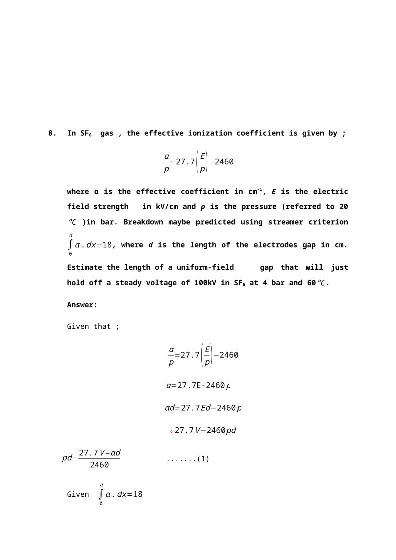
ρ 2d2=1.19(2.7)=3.27
√ ρ2 d2=√3.27=1.79
From equation (1) and (2);
0.91=A (0.25)+B(0.5)………………………………………………….(3)
88.38=A (3.27)+B(1.79)………………………………………………(4)
From (3) and (4);
[88.380.91 ]=[3.27 1.79
0.25 0.5 ][ AB ]
A=|[88.38 1.79
0.91 0.5 ]||3.27 1.790.25 0.5 |
=88.38 (0.5 )−1.79 (0.91)3.27 (0.5 )−1.79(0.25)
=35.75
B=|[3.27 88.38
0.25 0.91 ]||3.27 1.790.25 0.5 |
3.27 (0.91 )−88.38 (0.25)3.27 (0.5 )−1.79 (0.25)
=−16.07
iii) d = 3 cm, p = 3000mbar, t = 20°C,
ρ20=p
1013×(273+20)(273+t )
¿ 30001013
×(273+20)(273+20)
¿2.96
ρd=2.96 (3 )
¿8.88
√ ρd=√8.88
¿2.98
∴V s=35.75(8.88)−16.07 (2.98)=269.57k
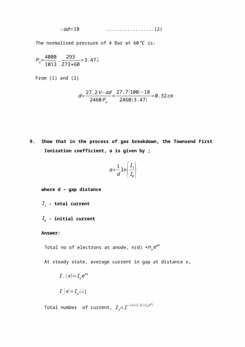
29. Describe the secondary process which can follow an electron avalanches and how
these processes may be identified. Show that the discharge current in a multi
avalanche Townsend process in non-attaching gas is given by:
I=Ioexp (αd)
1−ɣ [exp (αd ) ]−1
Answer:
When the d.c. voltage is applied and when the voltage is low, the current pulses start
appearing due to electrons and positive ions as shown in Figs.(a) and (b). These
records are obtained when the current is measured using a cathode ray oscillograph.
When the applied voltage is increased, the pulses disappear and an average dc.
current is obtained as shown in Fig.(c) In the initial portion (To), the current increases
slowly but unsteadily with the voltage applied. In the regions TI and T2, the current
increases steadily due to the Townsend mechanism. Beyond T2 the current rises
very sharply, and a spark occurs.
Fig. Current as a function of time
(a) When secondary electrons are produced at the cathode by positive ions.

(b) When secondary electrons are produced by photons at the cathode. ideal,
actual. I(t) is the total current and I+and are electron ion currents. τ-andτ+are the
electron and ion transit times.
Fig. (c) Typical current growth curve in a townsend discharge
Number of electrons reaching the anode;
nd=n0e(αd)
Average current = the number of electrons travelling/sec
I=I oe(αd )
α : average number of ionizing collisions made by an electron per cm travel in the
direction of the field. (is called Townsend’s first ionization coefficient)
I o = initial current at the cathode
Let :
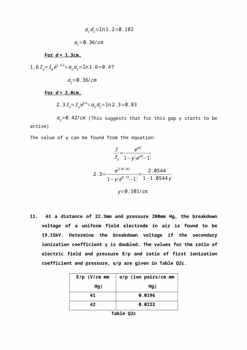
n0: electrons emitted from the cathode
n0’ = number of secondary electrons produced due to secondary (y)
processes.
n0 = total number of electrons leaving the cathode.
Then,
n0= n rsub 0 ' + n rsub 0׳
The total number of electrons n reaching the anode becomes,
n=n0 e ^ ( αd ) = ( n rsub 0 + n rsub 0 ׳ ) e ^ ( αd ) ¿
And
n0 Y=׳ ¿
Eliminating n0 ׳
n=n0 e ^ ( αd ) over 1 - γ left [e ^ ( αd ) right ] - 1 ¿ Or
I= Ioe(αd )
1−γ [e(αd )]−1
30. What is meant by ‘time lag to breakdown’ and describe how it may be influenced
and exploited.
Answer:
Time lags for breakdown:
In practical, the breakdown due to the rapidly changing voltages or impulse voltages,
there is a time difference between the application of a voltage sufficient to cause
breakdown and the occurrence of breakdown itself time lag.
t :time lag.
ts: The time during the voltage applications until a primary electron appears to initiate
the discharge and is known as the statistical time lag.
tf: The time required for the breakdown to develop once initiated and is known as the
formative timelag.

31. Describe with diagrams the principle breakdown mechanisms which can occur
in solid dielectrics and identify their order of occurrence on a stress-time
diagram.
Answer:
Breakdown In Solid Dielectrics
Solid insulating materials are used almost in all electrical equipments, be it an electric
heater or a 500MW generator or a circuit breaker, solid insulation forms an integral
part of all electrical equipments especially when the operating voltages are high. The
solid insulation not only provides insulation to the live parts of the equipment from the
grounded structures, it sometimes provides mechanical support to the equipment.
The processes responsible for the breakdown of gaseous dielectrics are governed by
the rapid growth of current due to emission of electrons from the cathode, ionization of
the gas particles and fast development of avalanche process. When breakdown occurs
the gases regain their dielectric strength very fast, the liquids regain partially and solid
dielectrics lose their strength completely. The breakdown of solid dielectrics not only
depends upon the magnitude of voltage applied but also it is a function of time for
which the voltage is applied. Roughly speaking, the product of the breakdown voltage
and the log of the time required for breakdown is almost a constant.
Vb = 1n tb = constant

Figure. Variation of Vb with time of application
The dielectric strength of solid materials is affected by many factors viz. ambient
temperature, humidity, duration of test, impurities or structural defects whether a.c, d.c.
or impulse voltages are being used, pressure applied to these electrodes etc. The
mechanism of breakdown in solids is again less understood. However, as is said
earlier the time of application plays an important role in breakdown process, for
discussion purposes, it is convenient to divide the time scale of voltage application into
regions in which different mechanisms operate. The various mechanisms are:
(i) Intrinsic Breakdown
(ii) Electromechanical Breakdown
(iii) Breakdown Due to Treeing and Tracking
(iv) Thermal Breakdown
(v) Electrochemical Breakdown
( i) Intrinsic Breakdown
Occurs at a very short duration of HV applied (10-8 s).
Depends on the presence of free electron, which capable of migration thru the lattice of
the dielectric.
Electronic breakdown
Assumed to be electronic in nature.
Initial conduction electrons density assumed to be large – electrons collisions occur.
Electrons gain energy and cross to conduction band. The process is repeated and more
electrons are developed in conduction band.

( ii ) Electromechanical Breakdown
Due to electrostatic compressive forces that exceed mechanical
Compressive strength.
The highest apparent electric stress before breakdown, if the thickness of specimen do
is compressed to d under applied HV;
Vd=√ 2 γ
ε o εr
ln1.67∨ Vd0
=Ea=0.6[ γε0 ε r ]
12
Mechanical instability occurs when d/do = 0.6, and Y : Young’s modulus and
depends on mechanical stress
( iii ) Breakdown Due to Treeing and Tracking
Occurs over a long time of electrical stress; presence of conducting path. Leakage
current phenomena – formation of spark and carbon track.
Treeing occurs due to the erosion of the material at the tips of the spark. Breakdown
channels spread through the insulation – formation of conducting channels.
Surface Tracking – caused by dry-band arcing. Formation of carbon track on the
insulation surface.
Tracking occurs even at low voltages, whereas treeing requires high voltage.
( iv ) Thermal Breakdown
Conduction current flows – heats up the specimen and the temperature rises.
Heat generated transfers to the surrounding medium by conduction and radiation.
Breakdown occurs when heat generated > heat dissipated.
Heat generated is proportional to the frequency – thermal breakdown is more
serious at high frequency.
Thermal breakdown stresses are lower under a.c. condition then d.c.
( v ) Electrochemical Breakdown
Chemical and electrochemical deterioration and breakdown---presence of air and other
gases – Chemical reactions occur.
Oxidation – surface cracks.
Hydrolysis – lose electrical and mechanical properties.
Chemical action – chemical instability – oxidation, cracking and hydrolysis.
Chemical and electrochemical deterioration increases very rapidly with temperature.

32. Measurement of breakdown voltage in a uniform-field spark gap in air gave the
results as shown in Table Q12.
Gap Spacing
(mm)
Pressure
(Bar)
Temperature
(°C)
Humidity
(g/mᵌ)
Breakdown
Voltage,Vs
( kV)
2.5 1.03 30 9 0.90
27 1.18 15 12 88.56
Table Q12
Using the expression derived from Paschen’s law,
Vs=A ( ρd )+B ¿
i) Determine the relative air density preffered to standard
atmospheric conditions of 1013.25 mbar and 20°C.
ii) The value of constant A and B.
iii) The breakdown voltage of a 3-cm gap spacing at a pressure of
3000 mbar and temperature of 20°C.
Answer:
i) d = 0.25cm, p = 1034mbar, t = 30°C, Vs = 0.90W
ρ20=¿ P1013
. 273+20273+t
¿
¿ 10341013
.293303
¿0.99
d = 2.7cm, p = 1180mbar, t = 15°C, Vs = 88.56kV

ρ20=¿ 1180
1013. 298288
¿
¿0.99
ii)
V 11( g
m3 )=V 9+V 9 .∆ V
¿V 9(1+∆ V )
¿0.90(1+0.002 (2 ))
¿0.91 KV
V 11( g
m3 )=V 12(1−∆ V )
¿88.56 (1−0.002 (1 ))
¿88.38 KV
Vs1=A ( ρ 1d1 )+B ¿
Vs2=A ( ρ 2d 2 )+B ¿
ρ 1d1=0.99 (0.25 )=0.25
√ ρ1d 1=0.5
√ ρ 2d2=1.21 (2.7 )=3.27
√ ρ 2d 2=1.81
Hence, from (x)
0.91=A (0.25 )+B (0.5 )………(1)
88.38=A (3.27 )+B (1.81 )…… …(2)
From equation 1 ;
0.91=A (0.25 )+B (0.5) ………………………..(a)
(x)

88.38=A (3.27 )+B(1.81)………………………(b)
(88.380.91 )=(3.27
0.251.810.5 )(AB )
A=|88.38 1.81
0.91 0.5 ||3.27 1.810.25 0.5 |
¿88.38 (0.5 )−1.81(0.91)3.27 (0.5 )−1.81(0.25)
¿ 44.19−1.651.64−0.45
¿35.75
B=|3.27 88.380.25 0.91 ||3.27 1.810.25 0.5 |
¿3.27 (0.91 )−88.38 (0.25)
1.19
¿−16.07
Solve the simultaneous equation, hence we get the value of :
A = 35.75
B = -16.07
iii) The breakdown voltage of 3-cm gap spacing at pressure of 3000 mbar and a
temperature of 20ºC
d = 3cm , p= 3000mbar, t = 20°C
ρ20=30001013
.293293
¿2.96

ρd=2.96 (3 )=8.88
√ ρd=2.98
Hence,
V s=35.75 (8.888 )−16.07 (2.98)
¿317.46−47.89
¿269.57kV
33. For a gap spacing of 3cm in a non-attaching gas, the breakdown voltage was
found to be 20kV. Determine the new breakdown voltage if secondary ionization
coefficient, γ is doubled given that α = 0.02 x 10⁻⁷
Answer:
Given d=3cm Vs=20kV α=0.02×10⁻⁷
Find Vs when γ is double
I=I 0 e(αd )
1−γ [e(αd )]−1
E=V s
d
From Townsend’s breakdown criterion for non attaching gas
γ [e(αd )−1 ]−1=0 or γ e(αd )=1
E=V s
d=20kV
3 cm=6.667 kV /cm
from Breakdown criteria γ is double α------α 1
γ e(αd )=2 γ e(αd )=1
e(αd )
e(α1 d)=2
(α−α1 )d=ln2
(α−α1 )= ln2d= ln 2
3=0.231
(α 1 )=0.02×10⁻⁷−0.231=−0.231

34. In a strongly inhomogeneous field, external partial discharge occur at
electrode of small radius of curvature when a definite voltage is exceeded.These
are referred to as corona discharge and depending upon the voltage,amplitude,
they result in a larger number of charge pulses of very short duration. With the
aid of diagram where appropriate;
i) Define the terms corona.
ii) Types of corona and how it occurs.
iii) The problems which are created by corona discharges on high
voltage transmission lines
Answer:
i) The term corona is used to describe phenomena which occur at highly-
stressed electrodes prior to the complete breakdown of the gap between the
electrodes. It is a partial discharge in air around a sharp point or thin wire in a
strong, non-uniform field. It is characterized by a visible glow, an audible
noise, radio interference, chemical effects such as production of ozone and
loss of electrical power. It occurs whenever the local voltage gradient exceeds
the ionization value of the air and depends on the air density, humidity and
the outdoor situations whether it is fair weather or raining and also the
roughness of the conductor surface.
ii) Corona can be classifieds into:
DC Corona
Positive Corona (anode)
When the highly-stressed electrode is anode, the following corona modes are observed
as the voltage is increased.
Onset Streamers
Also known as ‘burst’ pulses, these are intermittent, filamentary discharges which
propagates only a short distance from the highly-stressed electrodes.
Hermstein glow

As the voltage increased, the intermittent streamer discharge give way to a steady glow
discharges. This transition occurs when a large enough negative-ions space is
generated near to anode to give a quasi-uniform field in that region.
Breakdown Streamers
Eventually, the shielding effect of the glow discharge is not able to prevent the formation
of large streamers which propagate well into the gap.
Negative corona.
When the highly-stressed electrode is negative, three modes are again observed.
-Trichel Pulses
These differ from the burst pulses in that their magnitude and repetition
frequency are both very regular.
-Cathode glow
As the voltage is raised a critical trichel pulse repetition frequency is reached
and the repetitive discharge is replaced by a steady cathode glow.
-Negative streamers
These discharges are usually known as negative feathers to avoid confusion
with positive streamers discharges. They develop out of the glow mode and a
long rise time compared with other pulsating coronas.
1) AC Corona
With an alternating voltage applied, the same basic corona types will appear although
their characteristics may be altered to an extent which depends on the gap length;
- Small gaps (d ≤ 100cm)
Here, the ions generated in any of the corona modes above are able to cross the gap
during one half cycle of the voltage. Space charges will therefore not persist from one
half cycle to the next and the corona modes will therefore be similar to those for direct
voltages, although all three modes may be observed in one half cycle.
- Large gaps (d ≤ 1m)
For those gaps, space charge can persist from one half cycle to the next and can have
an effect on the corona modes observed. The usual effect is to enhance the positive-

glow phase. Further, the negative streamer is never observed in ac-stressed gaps, since
its onset potential is higher than the positive polarity breakdown voltage. Breakdown
always occurs on the positive half cycle.
2) Transmission Line Corona
The above description of the types of corona discharge referred particularly to the
point-plane gap where there is a single site for discharge to occur. On a transmission
line, corona may occur anywhere on the line and the average corona currents will be
much higher.
iii) The problems which are created by corona discharges on high voltage
transmission lines are:
Power losses
The power losses depend upon the maximum gradient for which the line is designed.
For a single conductor, this occur at the conductor surface. For a given cross-section of
conductor repaired for current carrying capacity, the maximum stress may be
reduced by using bundled conductors in which 2, 4 or 6 wire assembly is used.
Radio Interference
Radio interference is caused only by the pulse corona modes and only Trichel pulses
and positive streamers are of interest. The positive streamers usually have shorter
risetimes than the Trichel pulses and greater amplitude, so that the rate of change of
current is greater and their RI effect is therefore greater. These corona discharges
cause radiation of electromagnetic wanes.
Audible noise.
Recent studies on EHV and UHV lines indicate that audible noise may be a problem
where such lines pass near inhabited areas. Difficulties arise in monitoring such
noise levels as the ‘apparent noise’ is a nonlinear function of frequency. Measuring
instruments have thus been developed which have a similar response to the human
ear and levels have been set based limits at which most people find the noise
objectionable.

TAI(t)URRt
β-αTUTA UTTZg∆TZt
TT
35. Figure Q2 (a) shows a schematic diagram of a tiled transmission line tower.
Consider the tower top is struck by the lightning current i(t)and causes voltage
rise to u(t).
Figure Q2 (a)
Show that
u (t )=Z g Z t / (Zg+2Z t )i (t )
where,
Zg, is the surge impedance of the ground wire
Z t, is the surge impedance of the tower
u (t ),is the impulse surge function
∆ T ,is time of surge propagation from tower top to the cross-arm
i (t ), is the current wave function
T T, is time of surge propagation from tower top to the tower footing
T A,is time of surge propagation from tower cross-arm to the tower
footing
RT ,is tower footing resistance
Answer:

TAI(t)URRt
β-αTUTA UTTZg∆TZt
TT
Zeq=Zg Z g Z t
¿Zg
2Z t
¿
Zg
2× Z t
Z g
2+Z t
¿Zg Z t
Zg+2 Z t
u (t )=Zeq i (t )
¿Zg Z t
Zg+2 Z t
i (t )
36. Show whether the following equation is right or wrong (write the detail
derivation in order to prove it).
UTT (t )=u ( t )−αT (1+β)u (t−2T T )−(αT β )u ( t−4T T )+(αT β )2 u¿
Where,
UTT (t ), is the potential distribution on the top of tower
UTA ( t ),is the potential distribution on the top of tower cross-arm
Alpha(α ), is the coefficient of reflection
Beta(β ), is the coefficient of reflection on the tower to

TAI(t)URRt
β-αTUTA UTTZg∆TZt
TT
-αt=α0
UTA β∆T UTT
V1
α 3β 3UTT
α 2β 2UTT
αβUTT
α 3β 2UTT
α2βUTT
αUTTUTT
V2
V3
V4
I(t)
Answer :
UTT=V 1+V 2+V 3+V 4
¿u ( t )+α (1+β )u (t−2T t )+α 2 β (1+β )u (t−4T t )+α 3 β2 (1+ β )u (t−6T t )
¿u ( t )+α (1+β )u (t−2T t )+αβu (t−4 TT )+α 2 β2ut−6T T ¿+...¿

Disconnected
151413
Disconnected Disconnected
5
12
17
67891011
1 432
200 V
16
100 V
Disconnected
151413
Disconnected Disconnected
5
12
17
67891011
1 432
200 V
16
100 V
Replace α=−αt
¿u (t )−α T (1+ β )u (t−2TT )−(αT β )u (t−4T T )+(α T β )2u (t−6T T )+...¿
The equation proves that UTT is right
37. Use the iteration method to find the finite difference approximation to the
potentials at points 1, 2, 3, 9 and 15 of the system in Figure Q2(c). (Limit the
iteration up to 2 only). The nodal voltage follows the sequence as shown in
FigureQ2(c) that is node number is 1, 2, 3, 4, 5, 6, 7 up to 16 respectively.
Answer:

The general formula:
V 0=V 1+V 2+V 3+V 4
4
Iteration 1:
V 1'=200+0+0+100
4=75V
V 2'=200+0+0+75
4=68.75V
V 3'=200+200+0+68.75
4=117.2V
V 4'=200+200+0+0
4=100V
V 5'=117.2+100+0+0
4=54.3V
V 6'=68.75+54.3+0+0
4=30.76V
V 7'=75+30.76+0+0
4=26.44V
V 8'=100+26.44+0+100
4=56.61V
Iteration 2:
V 1' '=200+68.75+26.44+100
4=98.8V
V 2' '=200+117.2+30.76+98.8
4=111.7V
V 3' '=200+200+54.3+111.7
4=141.5V
V 4' '=200+200+0+54.3
4=113.6V
V 5' '=141.5+113.6+0+30.76
4=67.97V

V 6' '=111.7+67.97+26.44+0
4=51.53V
V 7' '=98.8+51.53+0+56.61
4=51.7V
V 8' '=100+51.7+0+100
4=62.92V
Result:
Potentials at point : P1= 100V
Potentials at point : P2=98.8V
Potentials at point : P3=111.7 V
Potentials at point : P9=51.53V

CHAPTER 3
LIGHTNING OVERVOLTAGE
(QUESTION AND ANSWER)
Q1. (a) With the aids of suitable labelled diagrams, discuss three
possible discharge paths that can cause surges on the transmission
line.
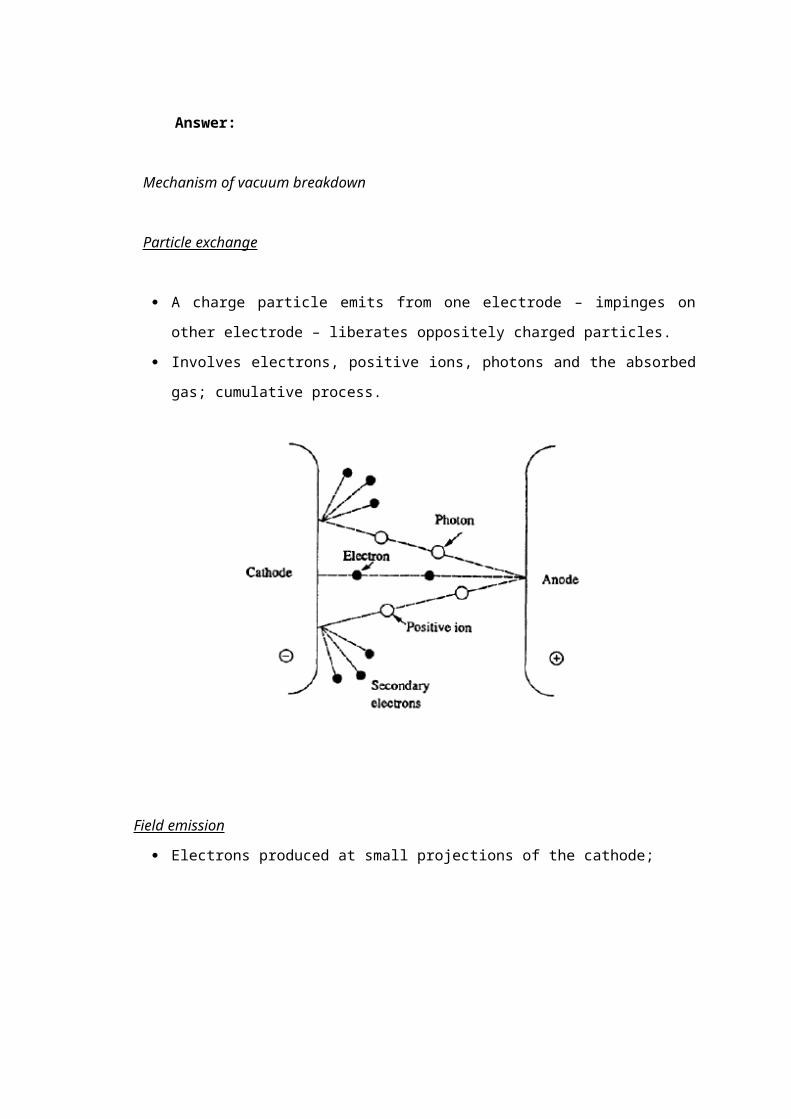
(b) A lightning stroke which reachs a peak current of 35 kA in 1 µs
strikes a 20 m tower on a 345 kV transmission line. The line has a
ground wire joining the tops of the towers; its surge impedance is 520
Ω. The tower surge impedance os 90 Ω and the ground footing
resistance is 40 Ω.
Determine whether the line insulations will flashover as a consequence
of the surge, assuming that their impulse flashover strength is 1050 kV.
A coupling factor 0.3 with the phase conductor can be assumed; the
impedance of the stroke channel can be ignored; a wave velocity on the
tower of 2.98 x 10⁸ m/s can be assumed. Show the surge progressions in
the form of Bewley lattice diagram.
SOLUTION:-
(a) 2 leader core
earth wire space charge envelope
3
Tower conductor
Tower footing resistance
Earth place
Figure 1 – Geometry of lightning leader stroke and transmission line
In the first discharge path (1), which is from the leader core of the lightning
stroke to the earth, the capacitance between the leader and earth is
discharged promptly, and the capacitance from the leader head to the earth
wire and the phase conductor are discharged ultimately bt travelling wave
action, so that a voltage is developed across the insulator string. This is

known as the induced voltage due to a lightning stroke to nearby ground. It is
not a significant factor in the lightning performance of systems above about 66
kV, but causes considerable trouble on lower voltage systems.
The second discharge path (2) is between the lightning head and the earth
conductor. It discharged the capacitance between these two. The resulting
travelling wave comes down the tower and, acting through its effective
impedance, raises the potential of the tower top to a point where the
difference in voltage across the insulation is sufficient to cause flashover from
the tower back to the conductor. This is the so-called back-flashover mode.
The third mode of discharge (3) is between the leader core and the phase
conductor. This discharges the capacitance between these two and injects the
main discharge current into the phase condustor, so developing a surge
impedance voltage across the insulator string. At relatively low current, the
insulation strength is exceeded and the discharge path is completed to earth
via the tower. This is the shielding failure or direct stroke to the phase
conductor.
(b)
20m
I
35 kA
α3 Β2
α2
ZT = 90Ω
α1
40Ω 40Ω

1 µs t
Equivalent circuit
Find Zeq :
1
Zeq
= 1ZT
+ 1Zg
+ 1Zg
1
90+ 1
520+ 1
520
Zeq = 66.86 Ω (1 Mark)
Find V surge :
V = Imax x Zeq
= 35 x 103 x 66.86
= 2.34 MV
= u(t) (1 Mark)
Find α and β :
α1 = R−ZT
R+ZT
= 40−9040+90
= -0.385 (1 Mark)
α2 = Z g Zg−ZT
Z g Zg+ZT
35kA ZT
Imax
Zg Zg

= 520520−90520 520+90
= 260−90260+90
= 0.486 (1 Mark)
β2 = 1 + α2
= 1 + 0.486
= 1.486 (1 Mark)
Time taken for wave travel from tower top to tower base
∆t = DistanceVelocity
= 20
2.98x 108 = 0.067 µs = 1 T (1 Mark)
No of travel in 1 µs after the lightning strike
0.067 µs → 1T
1 µs → 1
0.067 = 14.9 T

V1 = u(t)
V2 = α1β2 u(t - 2T)
= (-0.385)(1.486) u(t – 2T)
= -0.572 u(t – 2T)
V3 = α12α2β2 u(t – 4T)
= (-0.385)2(0.486)(1.486) u(t – 4T)
= 0.107 u(t – 4T)
V4 = α13α2
2β2 u(t – 6T)
= (-0.385)3(0.486)2(1.486) u(t – 6T)
= -0.02 u(t – 6T)
V5 = α14α2
3β2 u(t – 8T)
= (0.385)4(0.486)3(1.486) u(t – 8T)
= 0.0037 u(t – 8T)
V6 = α15α2
4β2 u(t – 10T) V7 = α16α2
5β2 u(t – 12T)
= (0.385)5(0.486)4(1.486) u(t – 10T) = (0.385)6(0.486)5(1.486) u(t – 12T)
= -0.0007 u(t – 10T) = 0.00013 u(t – 12T)
V8 = α17α2
6β2 u(t – 14T)
= (0.385)7(0.486)6(1.486) u(t- 14T)
= -0.00002 u(t – 14T)

Vtt = V1 + V2 + V3 + V4 + V5 + V6 + V7 + V8
= u(t) – 0.572 u(t – 2T) + 0.107 u(t – 4T) – 0.02 u(t – 6T) + 0.0037 u(t – 8T)
– 0.0007 u(t – 10T) + 0.00013 u(t – 12T) – 0.00002 u(t – 14T)
(4 Marks)
From graph,
Vpeak = 0.56 u(t) Vphase conductor = 0.3 Vpeak
= 0.56 (2.34 x 10⁶) = 0.3 (1.31 x 10⁶)
= 1.31 MV (1 Mark) = 0.393 MV (1 Marks)
Vflashover = Vpeak – Vphase conductor + Vphase
= 1.31 x 10⁶ – 0.393 x 10⁶ + √2 x345 x 103
√ 3
= 1.12 MV (1 Marks)
Vflashover strength = 1050 kV = 1.05
Therefore flashover occur because flashover ¿ flashover strength
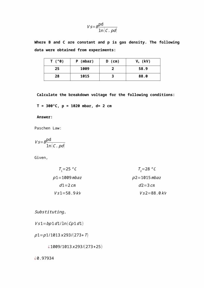
(3 Marks)

Q2. (a) Describe the lightning phenomena based on Simpson’s theory as
shown in Figure Q2a.
Figure 2a
(b) Explain what is meant by the terms ‘T1/T2 Impulse Wave’ and outline the
methode of lightning impulse voltage production in the laboratory.
SOLUTION:-
Q2. (a) According to Simpson’s theory as shown in the diagram below, there are
three essential regions the the cloud to be considered for charge formation.
Below region A, air currents travel about 800 cm/s and no rain drops fall
through. In region A, air velocity is high enough to break the falling rain drops
causing a positive charge spray in the clouds and negative charge in the air.
The spray is blown upwards but as the velocity of air decreases, the positively
charge water drops recombine with the larger drops and fall again. Thus
region A eventually becomes pre-dominately positively charged while region B
above it becomes negatively charged by air currents. In this upper regions in
the cloud the temperature is low (below freezing point) and only ice crystals
exists. The impact of air on these crystals makes them negatively charged,
thus the distribution of the charge within the cloud is shown as in the figure.

Lightning phenomena is based on the atmospheric process that takes place
during tunderstorm where charges are accumulated in the cloud or portion of
the cloud and equal and opposite charges are produced in the earth beneath.
These positive and negative charged become seperated by the heavy air
currents with ice crystals in the upper part and rain in lower parts of the cloud.
As the charges increases the potential between the cloud and the earth
increases and therefore the potential gradient is not uniformly distributed.
When the gradient exceeds the strength of the portion of air across which it is
applied, the air breakdown and a streamer starts from the cloud towards
earth. Lightning stroke may be started with potential of the order of 5 to 20 MV
between the cloud and the earth.
(b) An impulse voltage wave is a unidirectional voltage which rises rapidly to a
maximum voltage and the decays rather more slowly to zero as shown in the
diagram below.
V
100 %
90 %
50 %
10 %
T1 t
T2

The waveshape is generally defined in terms of the time T1 and T2 in
microseconds. T1 is the time taken by the voltage wave to reach its peak
value, i.e from 10% to 90% of the voltage wave. T2 is the total time from the
start of the wave to the instant when it has declined to one half of its peak, i.e
from start of the wave to 50% of the peak during decay.

Q3 (a) Will backflashover occur on a tower that was struck by lightning of
current I(t), of wave-shape with maximum value at 40kA occurring at 1.2µs and
decreased linearly. The surge impedance of tower, tower ground wire and
phase conductors are 200Ω, 250Ω and 300Ω respectively. The clearance
between the tower side and the phase conductor is 2 meter. Assume that the
breakdown of air is at 30kV per cm and the string insulator flashover at 1000kV.
Consider the coupling factor between ground wire and phase wire is 0.25. The
lighting strike when the A.C voltage is at [ 550√2√3 ] sin 110°kV.
Figure Q3(a) Transmission system with the top of tower was struck by lighting
(b) Figure Q3(b) shows a schematic diagram of a tilted transmission line
tower with two parallel ground wire and an impulse current wave-shape, i(t).
Consider the tower top is struck by the lighting current i(t) and voltage rises
to u(t).
Figure Q3(b)
(c) By referring to Fig Q3(b), discuss the validity of equation (write the
detailed derivation in order to prove it):

UTT (t) = u(t) - α T (1+β)[u(t -2TT) – (αTβ)u(t -4TT) + (αTβ)2u(t -6TT)….]
Where:
UTT (t) = potential distribution on the top of tower
α (Alpha) = coefficient of reflection
β (Beta) = coefficient of reflection on the tower top side
Solution:
(a) The ground potential rise at the point where lighting strikes the tower
Vsurge = 40 x 103 x [Z g∨¿ Zg∨¿ Z t ]
= 40 x 103 x [ Zg
2 x Z t
Zg
2+Z t
]= [ 250
2x 200250
2+200] 40kV
= [ 125 x 200325 ] 40kV = 3.08MV
(b) Zeq = Zg|| Zg|| Zg|| Zg||ZT
1Zeq
= 1Zg+ 1
Zg+ 1
Zg+ 1
Zg+ 1
ZT
= ZT+ZT+ZT+ZT+Z g
Zg ZT

=4 ZT+Zg
Z g ZT
Zeq = Z g ZT
4 ZT+Zg
So u(t) = i(t) . Zeq = Z g ZT
4 ZT+Zg
. i(t)
(c)
V1 = u(t) t = 0
V2 = (α + βα) u(t) t = 2TT
V3 = (α2β + α2β2) u(t) t = 4TT
V4 = (α3β2 + 32β3) u(t) t = 6TT
Β =UT Tα=α T
TT
Zg
Β α u(t)
V3
V2
TT
6TT
5TT
4TT
3TT
2TT
α u(t)
u(t)
Β α2 u(t)
Β2 α2 u(t)
Β2 α3 u(t)
Β3 α3 u(t)
V4
V1

VTT (t)=v1+v2+v3+v 4
= u(t) + (α + βα) u (t- 2TT ) + (α2β + α2β2) u (t- 4TT ) + (α3β2 + 32β3) u (t- 6TT )
= u(t)+α(1+β)[u(t -2TT) – (αTβ)u(t -4TT) + (αTβ)2u(t -6TT)….]
So the expression for VTT as given in the question is right
Q4 (a) Discuss in detail about the lighting phenomenon starting with the
formation of thunderclouds.
(b) A peak lighting current of 40kA has struck a ground wire at mid-span (at
the middle of two transmission towers). If the ground wire surge impedance is
given as Z=500Ω, calculate the generated voltage at the point of strike. State
the assumptions you made to answer this question.
Solution:
(a) During storms, charges are accumulated in clouds and equal charges of opposite
polarity are formed in earth. As these charges increases, the voltage gradient in
the air adjacent to the charge centre in the cloud increases.
When the gradient exceeds the insulation strength of air, a low current streamer
starts downward from the cloud and continues to grow. When the streamer
makes contact with the earth, it is like closing a switch between the two charges
of opposite polarity, one is the earth and the other in the streamer channel and in
the clouds . Thus large current flows.
In the middle stage of formation of a cloud, strong wind turbulence takes place
causing the separation of charges into several layers which are:
Intra-cloud (within the clouds)
Cloud to cloud
Cloud to ground
Cloud to air
Positive stroke or “Blue sky lightning”
(b)
I = 40kA
ZL =500ΩZL =500Ω

Assume:
1) Zs = infinity
2) No return voltage at the Earth line Zeq=Z /2
V at strike point, V=IZ /2=40 K x500 /2=10uV
ZS
Z Z
A

Q5 (a) Discuss two(2) of the followings
i. Lightning phenomena
ii. Direct strike and indirect strike
ii. Switching overvoltage
(5 marks)
(b) Lightning strike at mid-span of a transmission line ground wire at point a as
shown in Figure Q5(b). This wave travels in both direction of the
transmission line. Determine the transmission and reflection coefficients, β
and α at points b and d.
(10 marks)
Figure Q5(b)
(c) A lightning surge of magnitude 10 kA with the voltage waveshape of 1.2/50
µs strike a ground conductor at midspan of a transmission line. If the
channel surge impedance is 1500 Ω and the ground wire surge impedance
is 600 Ω, determine at the point of strike;
i. The equivalent circuit and equivalent impedance,
ii. The peak current, and
iii. The peak voltage.
R1
R2
ed
ZT1 ZT2
c Zg3Zg2bZg1

(10 marks)
Solution
(a)
i. Lightning Phenomena
Benjamin Franklin has proved lightning is an electrical phenomena. An Eletrical
phenomena carries the concept of charges involvement. So two types of charges are the
reasons for the cloud to be considered as a ‘cell’. The charge are a) positive type and
b)negative type. Fig. shows the typical thundercloud structure.
Not all clouds are lightning cloud generator. It is only the cumulonimbus cloud type that
can generate lightning. The Ice Splinter can be used to explain on the electrification of
the cloud. The moistures and precipitation particles being is suspension in air and due to
upwards action of updraft, causing supercooling to take place and resulting moistures to
become ice. The ionic migration of OH- and H- in the moistures built, leaving the OH- in
the front and II+ being lighter are pulled out to settle in the outer layer. The resultant two-
layer ice structure split due to different rate of ice expansion (the inner and outer layer).
The splinters are basically of positive-charged and negative-charged. The lighter
splinters are pulled upwards while the lighter negatively charged splinters settle at the
lower point of the cloud. If the electric field between the cloud and ground exceed the
dielectric strength of air, streamers will appear and propagate toward the ground. The
last jump of these streamers to the ground result upward streamers to move to attach
itself to the downwards-moving streamers. The attachment results in the process of
20km --
15km --
10km --
3km --
+ + + + + + + + + ++ + + + + + + + ++ + + + + + + +- - - - - - - - - --- - - - - - - - - --- - - - - - -

charges neutralisation of the positive and negative charges. This is known as return
strike. It causes large currents to flow to the ground.
[ 2.5 Marks ]
ii. (a) Direct Strike
Ground flash activities of lightning involve direct and indirect strike. If the
intend facilities or building or even structure for protection are struck by
lightning, which could end with structure damage and others, this is direct
strike.
(b) Indirect Strike
If the damage to building and equipment due to surge propagation is because
of inductive and capacitive affect. This is termed as indirect strike.
[ 2.5 Marks ]
OR
iii. Switching Voltage
With the steady increase in transmission voltages needed to fulfil the required
increase in transmitted power, switching surges have become the governing factor in
the design of insulation for EHV and UHV systems. In the meantime, lightning
overvoltage come as a secondary factor in these networks. There is a great variety of
events that would initiate a switching operations of greatest tolerance to insulation
design can be classified as follows:
a. Energization of a line
b. Load rejection
c. Switching on and off a equipment
d. Fault initiation and clearing [ 2.5 Marks ]
(b)
Point b is to be considered:
∝=Zg 2Zg 2
¿¿¿¿
Zt 1−Zg 1Zt 1+Zg 1
β=1+α

α=( Zg2 xZT 1
Zg 2+ZT 1−Zg 1)
Zg 2 x ZT 1Zg2+ZT 1
+Zg1=
Zg2 xZT 1−Zg 1(Zg 2+ZT 1)Zg2 xZT 1−Zg 1(Zg 2+ZT 1)
Point d:
α=R 1−ZT 1R 1+ZT 1
β doesnot exit
(c)
i. Based on the equivalent circuit:
Zg 1× Zg1
2Zg 1=600
2=300
ii Based on the circuit:
Zg1 Zg1
I peak
10kA10kA
I peak
1500 300

I peak= 15001500+300
×10=0.833× 10=8.33kA
iii . The peak voltage:
V surge=Zeq× Ipeak=300 ×8.33 kA=2499 kV=2.5MV
Q6. (a) A transformer has an impulse insulation level of 1175 kV and is to be
operated with an insulation margin of 15 % under lightning impulse conditions.
The transformer has a surge impedance of 400 Ω. A short length of overhead
earth wire is to be used for shielding the line near the transformer from direct
strikes. Beyond the shielded length, direct strokes on the phase conductor can
give rise to voltage waves of the from 1000e-0.05t kV (where t is expressed in µs).
If the corona distortion in the line is represented by the expression,
¿∆x
= 1β
(1−VoV ) μs /m
Where B = 100 m/µs and V₀ = 200 kV, determine the minimum length of
shielding wire necessary in order that the transformer insulation will not fail
due to lightning surges.
(10 marks)
Solution:
(a)
β= 2× 1600
1600+400¿1.6
For B.I.L of 1175 Kv, and an insulation margin of 15%, the maximum permissible
ZT=1600Ωβ
α1000e-0.05t
Zo =400Ω

voltage
¿1175×85
100
= 998.75kV
Since the voltage is increased by b= 1.6 times at the terminal equipment (transformer), the
maximum permissible incident voltage must be decreased by this factor, hence the
maximum permissible incident voltage is
=998.75/1.6
=624.22 kV
Therefore the shielding wire must reduce the surge to 624.22 kV(by virtue of the corona
distortion), that is
1000e-0.05t= 624.22
t = 9.425 µs
Hence ΔT = 9.425 µs
The corona distortion is given by
∆ tx= 1
B [1− 200624.22 ] μs/m
x=1525.53m
Therefore the minimum length of shielding wire required = 1.526 km.

Q7 (a) Discuss the following:
i. Backflashover of a lightning strike [2 Marks]
ii. Front time and tail time of lightning impulse voltage [2 Marks]
iii. The causes of switching surges [4 Marks]
(b) Prove that the reflection coefficient, α = (Z2 – Z1)/(Z2 + Z1) and the
transmission coefficient, β = 2Z2/(Z2 + Z1) for an incident lightning surge
on a transmission line where Z1 is the surge impedance of line 1 and Z2
is the surge impedance of line 2.
[4 Marks]
(c) A lightning current with the rate of rise of 25 kA/µs reaches a peak walue
in 1.6 µs has struck a ground wire at mid-span (at the middle of two
transmission towers). If the ground wire surge impedance is given as Zg
= 250 Ω, calculate the generated voltage at the point of strike. State and
justify all assumptions made.
If the striking point is changed to the top of one tower (not the end
tower) with a surge impedance of 100 Ω, calculate the generated voltage
at the point of strike.
[8 Marks]
Solution
(a)
i. Backflashover of a lightning strike

When a direct lightning stroke occurs on a tower, the tower has to carry
huge impulse currents. If the tower footing resistance is considerable , the
potential of the tower rises to a large value, steeply with respect to the line
and consequently a flashover may take place along the insulator strings.
This is known as “back flashover”.
(2 Marks)
ii. Front time and tail time of lightning impulse voltage
Front – time taken for the lightning impulse waveshape to rise from start
to peak value
Tail time – time taken for the lightning impulse waveshape to decay to
50% of it’s peak value
(3 Marks)
iii. The origin of switching surges in power system;
De-energizing of transmission lines, cables, shunt capacitor,
banks, etc.
Disconnection of unloaded transformers, reactors, etc.
Energization or reclosing of lines and reactive loads
Sudden switching off to loads
Shorcircuits and fault clearances
Resonance phenomenon like ferro-resonance, arcing grounds,
etc.
1.0
0.3
T2
T
T1
T1 =1.67TT’=0.3T1 =0.5T
T’
0.5
0.9

(3 Marks)
(b)
where, E & I – incident voltage and current
ET & IT – transmitted voltage and current
ER & IR – reflected voltage and current
No discontinuity of potential and current at junction J,
: E + ER = ET and I + IR = . . . (1)
E = Z1I, ET = Z2IT, ER = -Z1IR . . . . (2)
Substitute (2) into (1)
E/Z1-ER/ZR=(E+ER)/Z2.........(3)
By solving equition (3) gives;
Reflected coef., α , ER/E = (Z2 – Z1)/(Z2 – Z1)
Transmitted coef.,β, ET/E = 2Z2/(Z1 + Z2) (4 marks)
(c) i.
I = 25 x 1.6 = 40 kA,
Vsurge = IZeqv By assuming Zs=α;
= I(Zg//Zg)
= I(Zg/2)
Incident Wave
ER IR
ET IT
JE I
Reflected Wave
Transmitted Wave
I ZS zg Zg
Equivalent Circuit
VSURGE
I1

= 40 kA x 125
= 5 MV (4 Marks)
ii) By assuming ZS =α; Zg=250Ω; Zt =100Ω
Zeqv = (Zg/2) //ZT = Zt(Zg/2) =55.56Ω
(Zt + Zg/2)
: Vsurge = IZeqv
= 40 kA x 55.56
= 2.22 MV (4 marks)
Q8. (a) Fig. Q8 (a) shows a schematic diagram of a tilted transmission line
tower and an impulse current waveshape, i(t). Consider the tower top is struck
by the lightning current i(t) and voltage rises to u(t).
TT ZR
ZT u(t)
UR
Rt
Fig. Q8(a) Inverted tower for analysis
Also Zg is the surge impedance of the ground wire
Zt is the surge impedance of the tower
u(t) is the impulse surge function
i(t) is the current wave function
TT is the time of surge propagation from tower top to the tower footing
Rt is tower footing resistance
UTT(t) is the potential distribution on the top of tower
α is the coefficient of reflection on the tower bottom side
β is the coefficient of reflection on the tower top side
UTT(t)
i(t)βα
i(t)
Time (microsec)
Current (kA)

(i) Show that
u(t)= Zg Zt / (Zg + 2Zt ). i(t) (3 marks)
(ii) Determine whether the following equation is right or wrong (write
the detailed derivation in order to prove it)
UTT(t)=u(t)+αT(1+β)[u(t-2TT)+(αTβ)u(t-4TT)+(αTβ)2u(t-6TT)+……..]
V1=u(t)
V2=(α+ βα)
V3=(α2β+α2β2) u(t)
V4=(α3β2+α3β3) u(t)
t=0
t=2TT
t=4TT
t=6TT
TT
2TT
3TT
4TT
UTT
UtUt
=αUt
=αβ Ut
=α2β Ut
=α2β 2Ut
=α3β 2Ut
=α3β 3Ut
5TT

(b) A lightning current surge with the wave shape as shown in Fig Q8 (b), strike a
tower, which has a single ground wire in both directions. The characteristic are
as follows :
Surge impedance of lightning channel, Zl = infinity
Surge impedance of the tower, Zt = 150 Ω
Surge impedance of ground wire, Zg = 340 Ω
Velocity of wave propagation on lines = 298 m/ µs
Velocity of wave propagation on tower = 240 m/ µs
Height of tower = 30m
Effective tower footing resistance = 40 Ω
Lightning current peak magnitude = 40 kA
Based on Fig.8 (b), determine the maximum tower top potential for a duration 5
times the time of surge propagation from the tower top to the tower base after
the lightning strike the tower.
(15 marks)
Solution:
(a) i. u(t)= [Zg // Zt // Zg ] x i(t)
= Zg2
// Zt x i(t)
¿
Zg2
xZt
Zg2−Zt
x i (t )
¿ Zg x ZtZg−2Zt
x i ( t )
IDOrientation of propagation
20 µs 1 µs
Fig.Q8 (b) The simplified lightning current wave shape

ii. UTT=V1+V2+V3+V4
=u(t)- (α+βα ) u(t-2TT) - (α2β+α2β2) u(t-4TT) – (α3β2+α3β3) u(t-6TT)
=u(t)- α(1+β) [u(t-2TT) - αβu(t-4TT) – α2β2u(t-6TT)+…..]
Replace α = - αt
=u(t)- αt (1+β) [u(t-2TT) - αtβu(t-4TT) – αt2β2u(t-6TT)+…..]
The equation proves that UTT is right.
UTT=Ut(t) + β1α1ut (t-2 T) + β1α12 α2ut (t-4 T) + β1α1
3α22ut (t-6 T) +…..
=Ut(t) + (1 - β) α1ut (t-2 T) + β (1 - β) α12 α2ut (t-4 T) + (1 - β) α1
3α22ut (t-6 T) +…..
=Ut(t) + α1 (1 - β) [ut (t-2 T) - α1α2ut (t-4 T) + α12α2
2ut (t-6 T) +…..]
=Ut(t) + αT (1 - β) [ut (t-2 T) – (αTβ) ut (t-4 T) + (utβ)2 ut(t-6 T) +…..]
=Ut(t) + 0.579 (1 – 0.0625) [ut (t-2 T) – (0.579 x 0.0625) ut (t-4 T)]
=Ut(t) + 1.036 [ut (t-2 T) – (0.036)ut (t-4 T)]
=Ut(t) + 1.036ut (t-2 T) – 0.036ut (t-4 T)]
(b) The lightning current waveshape 1/20 µs
Comparison:
1 µs = 1/0.125 = 8 T
20 µs = 20/0.125 = 160
The Vsurge=
8 T
3.3 MV=1 pu
16 T
=Ut(t)
The peak voltage is 0.91 MV

Q9. (a) Discuss two (2) of the followings:
i. Lightning Phenomena (3 marks)
ii. Direct Strike and Indirect Strike (3 marks)
iii. Switching Overvoltage (3 marks)
(b) Lightning strike at mid-span of a transmission line ground wire at point a as
shown in figure Q9(b). This wave travels in both direction of the transmission
line. Determine the transmission and reflection coefficients, α and β at points b
and d.
UTT=Ut(t) + β1α1ut (t-2 T) + β1α12 α2ut (t-4 T) + β1α1
3α22ut (t-6 T) +…..
=Ut(t) + (1 - β) α1ut (t-2 T) + β (1 - β) α12 α2ut (t-4 T) + (1 - β) α1
3α22ut (t-6 T) +…..
=Ut(t) + α1 (1 - β) [ut (t-2 T) - α1α2ut (t-4 T) + α12α2
2ut (t-6 T) +…..]
=Ut(t) + αT (1 - β) [ut (t-2 T) – (αTβ) ut (t-4 T) + (utβ)2 ut(t-6 T) +…..]
=Ut(t) + 0.579 (1 – 0.0625) [ut (t-2 T) – (0.579 x 0.0625) ut (t-4 T)]
=Ut(t) + 1.036 [ut (t-2 T) – (0.036)ut (t-4 T)]
=Ut(t) + 1.036ut (t-2 T) – 0.036ut (t-4 T)]
(b) The lightning current waveshape 1/20 µs
Comparison:
1 µs = 1/0.125 = 8 T
20 µs = 20/0.125 = 160
The Vsurge=
R1 R2
ed
ZT1 ZT2
c Zg3Zg2bZg1

Figure Q9 (b)
(6 marks)
(c) A lightning surge of magnitude 10kA with the voltage waveshape of 1.2/50 µs strike a ground conductor at midspan of a transmission line. If the channel surge impedance is 1500Ω and the ground wire surge impedance is 600Ω, determine at the point of strike :
i. The equivalent circuit and equivalent impedance (2 marks)
i) The peak current (3 marks)
ii) The peak voltage (3 marks)
(d) A lightning current surge with the wave shape of figure 7 strikes a tower which
has a single ground wire in both directions. The characteristics are as follows;
Surge impedance of lightning channel = infinity
Surge impedance of tower = 150Ω
Surge impedance of ground wire = 340Ω
Velocity of the wave propagation on lines = 298 m/µs
Velocity of the wave propagation on tower = 240 m/µs
Coupling factor of phase conductors = 0.25
Height of tower = 30m
Effective tower footing resistance = 40Ω
Determine the maximum tower top potential, after 0.4 µs the tower has been
struck by the lightning. Please show clearly all the calculations involving

coefficients of the reflection and refraction. Show the surge progressions in
the form of the Bewley Lattice Diagram.
a) What will happen if the tower footing resistance increases in the value?
b) Provide one reason for the tower footing resistance increase in the value.
c) Why the speed of surge is higher in the conductor than in the tower
structure?
(17 marks)
25 kA
20 µs t 1 µs
Figure 9(d) the wave shape of the lightning current
Solution:
(a) i. Benjamin Franklin has prove lightning is an electrical phenomena. An
electrical phenomenon carries the concept of charges involvement. Two
types of charges are the reasons for the cloud to be considered as a ‘cell’.
The charges are:
a) Positive Type
b) Negative Type
Figure above show the typical thundercloud structure. Not all clouds are
lightning cloud generator. It is only the cumulonimbus cloud type that can
generate lightning. The Ice Splinter can be used to explain on the electrification
of the cloud. The moistures and precipitation particles being is suspension in air

and due to upwards action of updraft, causing super cooling to take place and
resulting moistures to become ice.
The ionic migration of OH- and H- in the moisture built, leaving the OH- in the front
and H- being lighter is pulled out to settle in the outer layer. The resultant two
layer ice structure split due to different rate of ice expansion (the inner and outer
layer). The splinters are basically of positive charged and negative charged. The
lighter splinters are pulled upward while the lighter negatively charged splinters
settle at the lower point of the cloud. If the electric field between the cloud and
ground exceed the dielectric strength of air, streamers will appear and propagate
towards the ground. The last jumps of these streamers to the ground result in
upward streamers to move to attach itself to the downwards moving streamers.
The attachment results in the process of charges neutralization of the positive
and negative charges. This is known as return strike. It causes large currents to
flow to the ground.
(a) ii.
Direct Strike
Ground Flash activities of lightning involve direct and indirect strike. If the
intend facilities or building or even structure for protection are struck by
lightning, which could end with structured damage and others, this is
direct strike
Indirect Strike
If the damage to building and equipment due to surge propagation is
because of inductive and capacitive affects. This termed as indirect
strike.
(a) iii.
With the steady increase in transmission voltages needed to fulfill the required
increased in transmitted power, switching surges have become the governing
factor in the design of insulation for EHV and UHV systems. In the meantime,
lightning overvoltage come as a secondary factor in these network. There is a
great variety of events that would initiate a switching surge in a power network.
The switching operations of greatest tolerance to insulation design can be
classified as follows:

a. Energization of a line
b. Load rejection
c. Switching on and off of equipment
d. Fault initiation and clearing
(b) Point b is to be considered:
α=Zg 2∨¿Zt 1−Zg 1Zg2∨¿Zt 1+Zg 1
β=1−α
α=
Zg2x ZT 1Zg2x ZT 1
−Zg1
Zg2 x ZT 1Zg2 x ZT 1
+Zg1
α=Zg 2 x Zt 1−Zg 1(Zg2+ZT 1)Zg2 x Zt 1+Zg1(Zg 2+ZT 1)
Point d:
α= R 1−ZT 1R 1+ZT 1
; β does not exist
(c) i.
Zeq= Zg1 x Zg12Zg 1
Zeq=6002
Zeq=300
(c) ii.
10kA
VTITi
ZgZgZs
Zg1Zg1

Ipeak= 15001500−300
x 10
Ipeak=0.833 x10
Ipeak=8.33kA
(c) iii The peak voltage
Vsurge=Zeq x Ipeak=300 x 8.33kA=2499kV=2.5 MV
(d)
Lightning Current Waveshape
25 kA
20 µsec t 1 µsec
Surge impedance of lightning channel = infinity
Surge impedance of tower = 150Ω
Surge impedance of ground wire = 340Ω
Velocity of the wave propagation on lines = 298 m/µs
Velocity of the wave propagation on tower = 240 m/µs
Coupling factor of phase conductors = 0.25
Height of tower = 30m
Effective tower footing resistance = 40Ω
Zeq = Zg//Zg//Zb
a

= 340//340//150
= 170x 150170+150
= 79.7
Step 1: To determine the potential at the top of tower at the point of lighting strike at the top
of the tower point of lighting strike
Equivalent circuit representation:
Vsurge = Î x Zc /¿ Zeq
= 25 x103 x Zeq Zc = Open Circuit
= 25 x103 x79.7
= 1.992 MV …………………………………………Assume this as 1 p.u
Step 2: To determine time for surge propagating from point a to foot of tower
t tt=30
240m /µs
= 0.125 µsec equivalent to T
Step 3: Calculation of coefficient
(i) Reflection
(ii) Refraction
VSurgeZeqZcÎ

Bewley Lattice Diagram
For a duration of a Tstrike = 0.4
0.125
= 3.2 T
α1 = R−Zb
R+Zb
= 40−15040+150
= -0.58
α2 = Z g/¿Zg−Z t
Z g/¿Zg+Z t
= 170−150170+150
= 0.0625
β = 2Z g/¿Z g
Z g/¿Zg+Z t
= 340320
= 1.063
Potential at tower top a
ua=ut (t )+ βα 1ut (t−2T )
Using graphical method to determine solution

PT 0
121+4+12
1
T µsec
The maximum tower top potential
(0.2 – 0.6p)
= 0.23 x 1.992 MV
= 0.456 MV
(i) The ground potential rise at the tower increases with the increase in tower
resistance.
(ii) Loss of moisture due to draught reason and the soil cannot retain moisture
due to bad soil condition.
(iii) The travelling wave is given by the relation V = 1
√LC . Since the tower has
higher conductance value as well as the capacitance, therefore
V t=1
LT CT
< −1LCCC
i.e; LT CT>LCCC
So, V c > V T
The speed of surge is higher in the phase conductor than in the tower structure.

Q10. (a) Figure Q10 (a) shows a schematic diagram of a tilted transmission line
tower and an impulse current waveshape, i(t). Consider the tower top is struck
by the lightning current i(t) and voltage rises to u(t).
Figure Q10(a)
Show that
u (t )=Zg Zt−(Zg+2Zt ) . i(t)
Where Zg is the surge impedance of the ground wire
Zt is the surge impedance of the tower
U(t) is the impulse surge function
T is time of surge propagation from tower top to the cross-arm
i(t) is the current wave function
TT is the time of surge propagation from tower top to the tower footing
TA is the time of surge propagation from tower cross-arm to the tower
footing
Rt is tower footing resistance
(2 marks)
(b) Show whether the following equation is right or wrong (write the
detailed derivation in order to prove it)
U TT(t)= u(t) – αT(1+ β) [ u(t-2TT)-( αT β)u(t-4TT) + ( αT β)2 u(t-6TT) ]
Where UTT(t) is the potential distribution on the top of tower
UTA(t) is the potential distribution on the tower cross-arm
Alpha (α) is the coefficient of reflection
Beta (β) is the coefficient of reflection on the top side
(5 marks)

c.
Figure Q11 (c) shows a partly distribution system of electrical power network
where an overhead line is connected to a set of three underground cables
connected each other point A, B and C respectively. At those respective points
a resistor R is connected to the ground. The line is struck by lightning at point
0H, 100m away from the underground cable UG1. The form of the lightning
current is:
I(t) = 3.0x10¹⁰t , 0 < t < 2.0 μs
= 6.0x10¹⁰ - 3.0x10⁸t , 2 < t < 101 μs
= 0 , t > 101 μs
Each underground cable is 300m length where Zoh, Za, Zb and Zc is equal to
450Ω, R=80Ω. Assume Z of lighthning channel impedance is infinity. Traveling
wave have the following velocities:
a) On the overhead conductors, 2.98x10⁸ m/s
b) On the underground cable 2.68x 10⁸ m/s

Calculate the first peak of voltage at point B after 3 microseconds the lightning
strike the overhead conductor and the time when it occurs.
(13 marks)
Solution:
(a) Zeq = Zg // Zg // Zt = Zg/2 // Zt
¿Z g /2x Z tZ g/2+Z t
x (t )=i ( t ) x Zeq
¿ i ( t ) x Z g /2x Z tZ g/2+Z t
=i (t ) x Zgx Z tZ g+2 Z t

U TT(t)= ut(t) + αUt(1+ β) (t-2TT) + α2 βu(t-4TT) + α2 β2 u(t-4TT) + α3 β2 u(t-6TT) + α3 β3
u(t-6TT)
= ut(t) + α (1+ β) ut (t-2TT) + α2 β3 (1+ β) u(t-4TT) + α3 β2 (1+ β) u(t-6TT)
= ut(t) + α (1+ β)[ ut (t-2TT)] + α β u(t-4TT) + (α + β)2 u(t-6TT)
(b)

(c)
Î = 3x1010 x 2x10-6
= 6x104 = 60KA 0<t<2us
Î =( 6x10⁴ ) – (3x108 x 2x10-6 )
= ( 6x10⁴ ) – ( 6x10² )
= 60000 – 600
= 59400 = 59.4KA
I = 0 Vsurge = 59.4 x103 x (450/2)
= 1.34mV
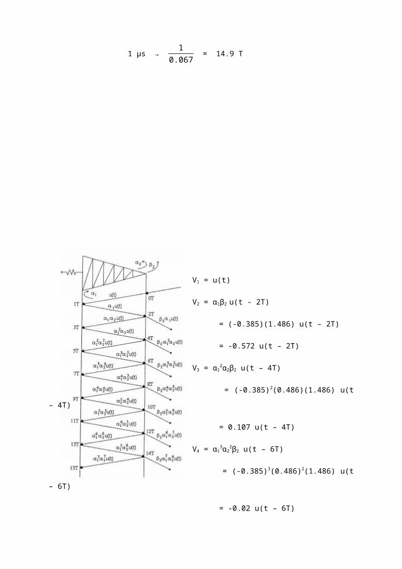
Time of travelling
At overhead line conductor
ΔOH – UG1 = 100 / (2.98 x10⁸)
= 33.6 x10 -8
= 0.34μs = ΔT

ΔUG1 = Δ UG2 = Δ UG3
= 300 / (2.98 x10⁸)
= 111.9 x10 -8
= 1.12 μs
ΔT = 1.12 μs
ΔUG1 = 0.34/1.12= 3.294
To simply the drawing
ΔUG1 = 3.00 AT
ΔOH – UG1 = (0.34/1.12) x 3.00 = 0.91 AT
Time frame = (3/0.34) x 0.91 AT = 8.02
α1 = (450-450)/(450 + 450)
= 0
β1 = 1 + α1 = 1
α2 = (6.79-450)/(67.9+ 450)
= - 0.738
β 2 = 1 + α2 = 0.262
α3 = -0.738, β3= 0.262
α4 = (80 - 450)/ (80 + 450)
= -0.698
β 2 = does not exist
Ut at B after 3 microseconds the lightning strike the overhead line = β 1 β 2 β 3 u(t-7ΔT)

VB = β 1 β 2 β 3 ut(t-7ΔT)
= 1 x 0.262 x 0.262 x ut(t-7ΔT)
= 0.069 ut(t-7ΔT)
The Zeq at lightning point of strike
= 450/2 = 225 Ω
Î =60KA
Vsurge = 225 x (59.4 x103 )
= 13.34MV
= 1 p.u
So that first peak voltage at point B after 3 microseconds the lightning strike the overhead
conductor is
= 0.069 x 13.34 MV
= 0.92 MV
The time it happen is 7ΔT + 2.0
= 7 x 0.34 + 2.0
= 4.38 μ

Q11 a. Discuss any two (2) of the followings:
i. Mechanism of lightning strike.
(4 marks)
ii. The difference between Simpson’s Theory and Reynold & Mason Theory
in explaining the phenomena oh charge formation in the clouds.
(4 marks)
iii. How does lightning strike can induce over voltages in power
transmission line?
(4 marks)
b. Protection of power transmission system from lightning strike is an important
aspect in the design of the system. A good design is to minimize the
disturbances due to lightning. Describe three (3) types of lightning protection.
It’s function and operation as a protection to the power system.
(6 marks)
c. Switching surge is an overvoltage that causes disturbances to power
transmission lines. With an increase in transmission voltage to over 400 kV,
the switching surface have caused problems as same as the lightning
overvoltage. Explain what is meant by switching overvoltage. It’s characteristic
and the methods of controlling the surge to prevent damage to the power
equipment. (6
marks)

Solution:
(a) i. Mechanism of lightning strike.
Stepped leaders propagating towards the ground
Strong attraction from the downwards stepped leaders cause oppositely charge streamers
appearing on various corners of the structure of the ground
Attachment of –ve charge downwards streamer with +ve charge upwards streamer. The final
jump is to the transmission power tower.

(a) ii. The difference between Simpson’s Theory and Reynold & Mason Theory in
explaining the phenomena oh charge formation in the clouds.
Teori Simpson
Menurut teori simpson ada tiga ruang penting dalam awan bagi pembentukan cas sepetri
didalam rajah diatas. Dibawah ruang A, kelajuan arus udara adalah melebihi 800cm/s dan
tidak terdapat titisan hujan yang jatuh. Dalam ruang A, kelajuan udara adalah tinggi untuk
memechkan titisan hujan menyebabkan percikan cas positif terbentuk pada awan dan cas
negative dalam udara. Percikan cas positif tersebut ditiup keatas tetapi dengan

pengurangan kelajuan udara, cas positif titisan air tersebut akan bercampur dengan titisan
yang lebih banyak dan jatuh kebawah. Ini menyebabkan ruang A akan bercas positif dan
ruang B keatas akan bercas negative. Pada ruang di bahagian atas awan suhu adalah
rendah dan hanya terdapat hablur ais. Kesan udara pada hablur ais tersebut menjadikannya
bercas negative.
Teori Reynold dan Manson
Menurut reynold dan manson, petir terhasil pada ketinggian antara 1 ke 2 km sehingga 12
ke 14 km dari paras bumi. Bagi pembentukan awan petir dan cas perlu ada arus udara,
lembapan dan julat suhu yang tepat. Arus udara yang dikawal oleh kecerunan suhu
bergerak keatas membawa lembapan dan titisan air. Titisan air didalam awan petir ditiup
keatas oleh arus udara dan mejadi beku sebagai hablur ais.pada suhu beku, hablur akan
bertambah dan bergerak ke bawah. Hablur tersebut membawa bersama-sama cas negative
ke ruang bawah awan sementara titisan air yang ditiup ke ruang atas awan membawa cas
positif. Proses pergerakan titisan air dan hablur ais ini yang menyebabkan berlakunya kilat.
(a) iii. How does lightning strike can induce over voltages in power transmission
line?

Sambaran Langsung
Kilat akan menyambar pada objek yang paling tinggi pada satu-satu kawasan. Talian
penghantaran adalah terdedah kepada sambaran kilat secara langsung. Sambaran terus
merupakan proses discas secara terus antara awan dan menara/dawai pengalir. Bila kilat
menjalankan cas negative pada hujung bumi, objek bumi (talian dan menara) akan
mengaruh cas positif. Disebabkan oleh penebat ke pengalir talian penghantaran. Talian
penghantaran akan berlagak sebagai kapasitor bercas positif. Cas yang teraruh ini akan
menyebabkan voltan lampau dan akan menghasilkan sambaran kilat. Voltan teraruh akan
merambar sepanjang talian, separuh akan dipantul (reflect) kebahagian lain talia. Pantulan
voltan teraruh ini boleh menyebabkan lampau kilat pada menara.
Sambaran tak langsung
Sambaran tak langsung atau sambaran teraruh merupakan discas awan pada sekitaran
menyebabkan keupayaan pengalir meningkat. Cas negative pada bahagian dasar awan
menyebabkan cas positif pada pengalir talian penghantaran yang berhampiran. Gelombang
begerak (travelling wave) voltan dan arus pada arah depan dan belakang sepanjang talian
penghantaran.

(b).
Peranti-peranti perlindungan kilat bagi system kuasa:
i. Sela Pembuangan (Expulsion Gap)
satu peranti yang mempunyai sela bunga api dengan pelindap kejutan arka (arc
quenching) yang memadamkan arka arus bila selaa tersebut pecahtebat
disebabkan oleh voltan lampau. Pada keadaan voltan lampau, kedua-dua sela
akan pecahtebat seretak dimana arka yang terhasil didalam tiub disebabkan oleh
arus kilat akan mengewap sebahagian bahan gentian. Gas yang terhasil dari
campuran wap air dan gentian akan memadamkan arka dan laluan menjadi litar
buka.
ii. Tiub Perlindungan (Protector Tubes)
Disambung dibawah pengalir pada menara talian penghantaran. Prinsip dan
kendalian sama seperti sela pembuangan. Bila voltan lampau berlaku, sela akan
pecahtebat dan arus akan dihadkan oleh rintangannya dan rintangan kaki
menara. Voltan lampau pada talian dikurangkan ke nilai kejatuhan voltan
melintangi tiub perlindungan.

iii. Penangkap Pusuan (surge arrester)
Peranti yang digunakan pada pencawang dan penghujung talian untuk mendiscas
voltan lampau kilat dan luruan penyuisan. Disambung secara selari dengan
peralatan yang dilindungi pada hujung talian atau tempat paling hampir dengan
pencawang. Ia akan mengurangkan voltan lampau ubahtika ke tahap bersamaan
dengan had penebatan peralatan. Elemen penghad arus adalah blok logam
oksida (metal oxide) yang mempunyai cirri-ciri rintangan yang tidak linear. Bila
arrester dipicu, blok logam oksida akan berada pada nilai rintangan yang rendah
untuk meghadkan arus. Bila arus luruan berkurangan, blok akan kembali ke nilai
rintangan tinggi.

(c).
Voltan lampau pensuisan merupakan voltan lampau yang terjana dalam system talian itu
sendiri. Voltan lampau tersebut boleh meningkat magnitudnya sehingga 6 kali ganda dari
voltan normal. Gelombang dedenyut pensuisan mempunyai tempoh masa yang lebih lama
dibandingkan dengan dedenyut kilat dan ia member kesan yang lebi teruk dari kilat.
Dedenyut pensuisan boleh terjadi disebabkan oleh penutupan dan pemutusan litar elektrik
menggunakan perkakasan suis (switchgear) dalam system kuasa yang mempunyai
kapasitan dan induktan yang tinggi. Dalam operasi pemutusan litar pusuan pensuisan
dengan kadar kenaikan voltan yang tinggi akan menyebabkan restriking berulangan dan
boleh merosakkan alat pemutus litar. Dedenyut pensuisan mengandungi frekuensi yang
tinggi serta pantulan gelombang dalam system.
Ciri-ciri pusuan pensuisan adalah berbeza-beza dan bergantung kepada punca asal
berlakunya dedenyut tersebut. Punca-punca berlakunya pusuan adalah :
‘De-energizing’ pada talian penghantaran, kabel shunt kapasitor
Pemutusan penyambungan transformer tanpa beban dan reactor
‘Energization’ atau penutupan(reclosing) talian dan beban reaktif.
Penutupan beban secara tiba-tiba.
‘Clearence’ kerosakan dan litar pintas
Fenomena salun seperti ferro-resonance, arching grounds

Rupabentuk gelombang dedenyut pensuisan adalah seperti dalam rajah dibawah.
Kawalan voltan lampau disebabkan oleh pensuisan boleh dilakukan dengan;
‘Energization’ bagi talian penghantaran dalam satu atau lebih langkah dengan
menyambungkan perintang dan mengeluarkannya semula selepas selesai proses
tersebut.
Kawalan fasa semasa penutupan pemutus litar
Pembuangan cas yang terperangkap sebelum pembukaan pemutus litar
Penggunaan reactor pirau (shunt reactor)
Pengurangan pusuan pensuisan menggunakan penangkap pusuan yang
bersesuaian.

Q12. (a) There are several different types of discharges in and around the
thundercloud. 90 percent of the discharges are cloud to ground lightning
discharge. A lightning strike basically involves attachment of downward leader
and the upward streamer originating from the ground or grounded structures.
Sometimes depending on the height of the building structures, lightning can
also triggered by an upward leader being attached to a downward stepped
leader coming from the cloud base. Based on these brief description of
mechanism of lightning flash, describe the basic of the Franklin Rod method of
lightning protection.
(3
marks)
(b) Fig. 12 (b) shows the damage of a building related to lightning strike. It also
shows the building is protected with a Franklin rod which is used as the basis for
lightning protection standard like IEC 62305 and others. Provide two reasons for
the lightning protection rod failure to provide protection to the building against
lightning strike.
Fig 12 (b) Lightning struck the sharp edge of a building top where the Franklin Rod is overlooking

(c) Figure 12 (c) shows the simulation of lightning strike a tower.
Figure 12 (c) Tilted Transmission Tower
(5
marks)
Based on Fig. 12 (c), shows that:
u (t )= ZgZt(Zg+2 Zt )
x i( t)
When Zg is the equivalent surge impedance of the ground wire
Zt is the surge impedance of the tower
u(t) is the impulse surge function
∆T is time of surge propagation from tower top to the cross-arm
i(t) is the current wave function
TT is time of surge propagation from tower top to the tower footing
TA is time of surge propagation from tower cross-arm to the tower
footing
Rt is tower footing resistance
Alpha(α) is the co efficient of reflection
Beta(β) is the co efficient of reflection on the tower top side
(2
marks)
(d) Fig. 12 (d) shows a tower with a 3 circuit ground wire system of Zg, 200
ohm(single circuit).The tower 30 meters high with surge impedance of 300 ohm.
The lightning current rises linearly to a peak of 60 kA in 2µs before commencing to
decline. Compute the potential UTT at the top of tower 0.21 microsecond after the
lightning strikes the tower top. Assume the lightning channel impedance is
i(t)
Time (microsec)
-αT β
i(t)
∆T
TT
UTT
ZG
RGUTA
UR
TA

infinity. The speed of lightning surge in the tower is 2.98x 10⁸ meter per second.
The tower footing resistance is 10 ohm.
Fig.12 (d) A typical transmission line tower (10 marks)
Solution:
(a) Describe the basis of Franklin Rod Method of Lightning Protection
Based on research, electrode with sharp edges will experience high electrical stress
on its tip due to electric field intensification when high voltage is applied. Before
downward streamer is within striking distance from a facility, an upward opposite
streamer will be launched from the facility as well as the Franklin Rod. A strike will
happen when both of these streamers attach together and cause lightning return
stroke. In another word, the Franklin Rod is the sacrificial point of lightning strike. The
current is the discharged to the ground terminal via the down conductor.
(b) Failure of Franklin Rod to function
i) Several upward streamers are produced at the approach of highly charged
downward streamers from the cloud base. The competitive upward streamers
attachment with cloud downward streamers can result in the streamers
Tower Footing Resistance R is 10 Ohm
Tower Footing
Tower Cross Arm
Ground Wires
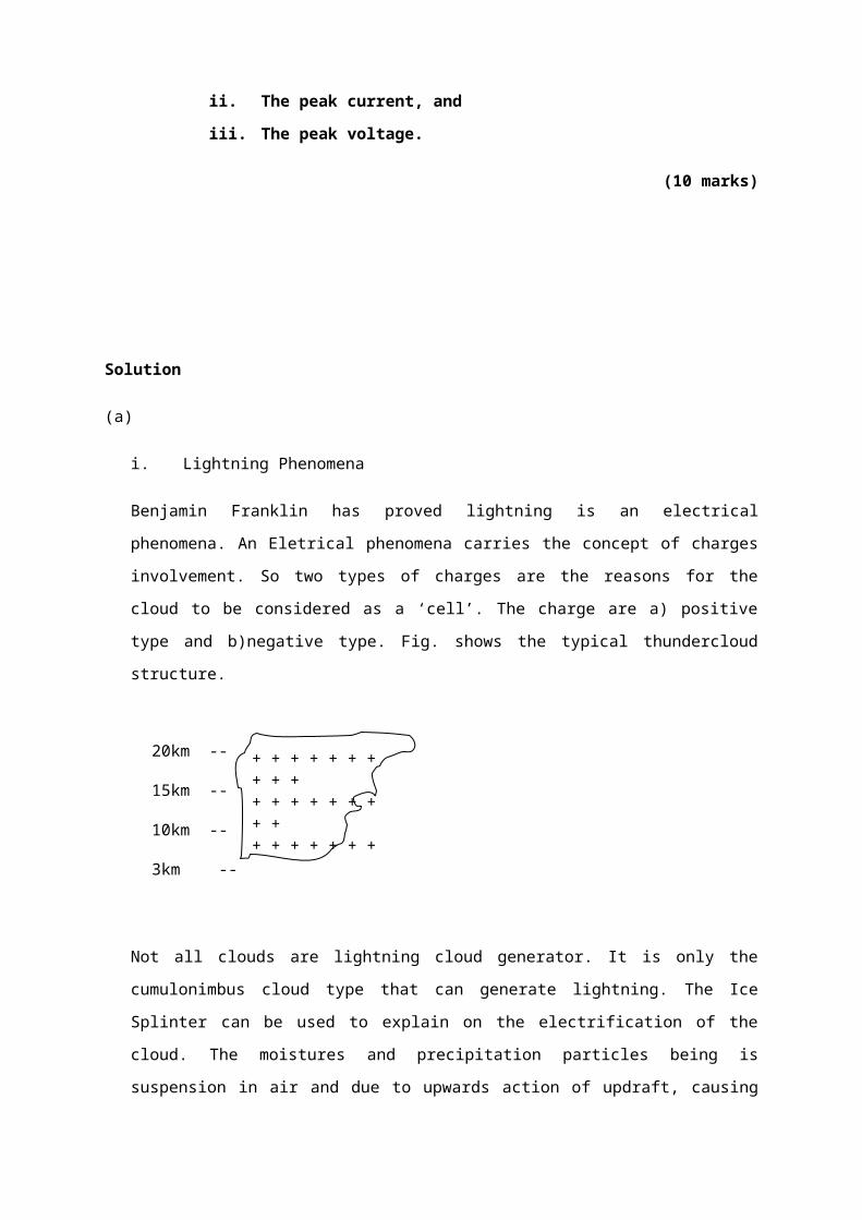
emerging from the building edges to overcome the streamers emerging from
the Franklin Rod.
ii) The lightning leader is of low current magnitude causes it to strike the building
from the side of the building. So the edge of the building is seen on the most
probable point of lightning strike.
(c)
At the point of strike,
Zequivalent (Zeq )=Zg/¿ Zt /¿Zg
¿
Zg2
x Zt
Zg2
x Zt
¿ ZgZtZg+2 Zt
The voltagesurge at the point of strike=I ( t ) x Zeq
¿ i (t ) x ZgZtZg+2Zt
¿ZgZt
Zg+2 Ztx i(t)
(d)
i(t)I(t)
Zg
Zg
Zt
δ
UTT60kA
2µs
Zt=300Ω
i(t)
-αT
β
Zg=200Ω
30
10Ω

Zg = 200Ω , Zt = 300Ω, R = 10Ω, Zl = infiniti
Zeq¿ZgZt
Zg+6 Zt
¿ 200 x300200+1800
¿30Ω
V surge ¿30Ω x60kV
¿1800kV
¿1.8 MV
Transit time from the tower top to the ground
∆t¿30
2.98x 108=10.07 x10−8
= 0.1 µsec
αT¿10−30010+300
=−0.935
-αT¿0.935=δ
β¿Zg /¿ Zg/¿ Zg/¿Zg /¿Zg /¿ Zg−Zt
ZTT+Zt
¿
Zg6−Zt
Zg6+Zt
¿
2006−300
2006+300
¿ 33.3−30033.3+300
=−0.80
ZTT

Zg
δβUt
βUt
δUt
Ut
Utt
3∆t
2∆t
∆t
UTT = Ut + αβUt
= U(t) + Ut(t-2∆t)(δ + β)
= Ut(t) + Ut(t - 2∆t)(δ + β)
= Ut(t) – 1.74 Ut(t-2∆t)
Resultant
-2p
-1p
1p
1.74 Ut(t-2∆t)
2µs
Ut(t)

Q13. (a) State the following :
i) Lightning strike mechanism
ii) Lightning strike parameter and characteristics
iii) Direct strike
iv) Indirect strike
v) Surge arrester ( 15 marks )
b) A 300m length of overhead earth conductor which is laid between two towers
is strike by a lightning. The lightning struck to a point of a distance of one third of
the length from one the tower. The surge earth conductor and tower impedances
were 300ohm and 100ohm respectively. The lightning strike carries 25 kA current
within 1.5µs and the surge impedance is about 1200ohm.Determine the surge
voltage at the tower top after the strike.
( 5 marks )
Solution:
i) Lightning strike mechanism
Apabila keamatan medan elektrik pada awan melebihi kekuatan dielektrik udara
yang terion yang lembap(~10kV/cm).Satu penjurus elektrik bergerak ke arah bumi
dengan kelajuan 1/10 dari kelajuan cahaya.Walaubagaimana pun, pergerakan
penjurus itu akan berhenti(selepas 50m) dan memancarkan kilat atau cahaya yang
terang.
Selepas lebih kurang 100µs, penjurus muncul kembali dan mengulangi proses tadi
untuk beberapa kali.Oleh kerana ia memerlukan beberapa penjurus pandu untuk
sampai ke bumi, maka ia dinamakan penjurus pandu bertangga(stepped
leader).Jumlah masa yang diperlukan bagi pandu bertangga untuk sampai ke bumi
adalah lebih kurang 20ms.
-2p

Sambaran kilat dan discas elektrik yang disebabkan oleh kilat diterangkan melalui
teori penjurus untuk discas bunga api di antara dua elektrod pada jarak yang panjang
dan medan tak sekata.Kilat mengandungi beberapa discas bermula dengan discas
pandu dan berakhir dengan discas kembali atau discas utama.Penjurus kembali
terbentuk apabila penjurus pandu telah mencecah bumi.Semasa pergerakan
penjurus pandu, cas positif bertumpuk pada hujung penjurus.Apabila mencecah atau
menghampiri bumi, keamatan medan elektrik pada bumi cukup besar untuk
menghasilkan penjurus kembali.Oleh itu cas positif tadi berpatah balik ke awan untuk
meneutralkan cas negative awan dan oleh itu arus yang besar mengalir dalam laluan
tersebut.Magnitud arus adalah dari 1000 ke 250 000 A.Kelajuan sambaran pandu
pemula ialah 1.5x107 cm/s.Sambaran seterusnya 108cm/s dan penjurus kembali
1.5x10⁹ ke 1.5x1010 cm/s(~0.05 ke 0.5 kelajuan cahaya).
Tempoh sambaran utama atau sambaran kembali ialah 100µs atau lebih.Setelah
sambaran kembali selesai, arus dalam julat yang lebih kecil (100 ke 1000 A) mungkin
terus mengalir untuk selama lebih kurang 20ms.Pengaliran arus ini akan
menyebabkan wujudnya sambaran-sambaran ulangan.Walau bagaimana pun,
sambaran ulangan ini bergerak pada halaju yang lebih kecil(~1% kelajuan cahaya)
dan tidak bercabang.Sambaran balik atau sambaran utama untuk sambaran ulangan
ini juga mempunyai arus yang lebih kecil.Jarak masa diantara sambaran ulangan
ialah 0.6 hingga 500ms dengan purata 30ms.Jumlah masa kesemua sambaran
berbilang ini mungkin mencecah lebih dari 1 saat.
Beberapa graf penting kilat ditunjukkan seperti dalam Rajah 1 hingga Rajah 8.

ii) Lightning strike parameter and characteristics
Diantara parameter penting kilat ialah
Amplitude arus dan agihan kebarangkaliannya.
Kadar naik arus dan agihan kebarangkaliannya.
Bentuk gelombang voltan.
Gelombang arus mempunyai bahagian yang mempunyai yang mempunyai
nilai yang kecil(beberapa ampere) tetapi untuk tempoh yang lama iaitu
beberapa milisaat.Ini boleh mengakibatkan kerosakan haba berlaku pada
peralatan kuasa.
iii) Direct strike

Masa ke puncak dan kadar naik juga merupakan cirri yang
penting.Kebanyakan arus sambaran kilat mempunyai kadar naik melebihi
7.5kA/µs manakala sebahagian (10%) yang lain pula melebihi 25 kA/µs.
Daripada pengukuran yang dibuat, sambaran kilat boleh mengakibatkan nilai
voltan pusuan setinggi 5000kV wujud pada talian penghantaran.Secara
purata, kebanyakan sambaran kilat menghasilkan voltan pusuan kurang dari
1000 Kv.Masa depan(front time) gelombang pusuan voltan biasanya di antara
2 hingga 10µs manakala masa ekor(tail time) pula dari 20 ke 100µs.Kadar
voltan pula ~1MV/µs.
iv) Indirect strike
Sambaran terus berlaku apabila proses discas secara terus berlaku diantara
awan dan menara atau dawai pengalir talian penghantaran.Manakala
sambaran teraruh berlaku disebabkan oleh proses discas diantara dawai
pengalir(yang mempunyai cas teraruh dari awan) dan bumi.
v) Surge arrester
Medan elektrik yang terhasil diantara awan dan bumi biasanya tidak
mendatangkan apa-apa kesan kepada dawai pengalir talian penghantaran
kerana ianya ditebat melalui penebat gantungan.Walau bagaimana pun jika
kecerunan medan adalah tinggi, kebocoran cas positif boleh berlaku dimana
cas tersebut mengalir dari menara ke dawai pengalir melalui permukaan
penebat gantungan.Proses ini mengambil masa beberapa ratus saat.Apabila
proses discas diantara awan dan sesuatu objek pada bumi berlaku, cas-cas
positif yang banyak masih lagi tertinggal pada dawai talian dan ini
mengakibatkan satu pemuat yang besar wujud diantara dawai talian dan
bumi.Oleh itu voltan lampau akan terhasil didalam dawai dan akhirnya satu
sambaran berlaku ke bumi.Oleh itu sambaran ini disebut sebagai sambaran
kilat teraruh(induced lightning stroke).
(b)

Litar setara pada pengalir bumi
Ia=IL xZg
Zg+Zg/¿ ZL
¿25k x300
(300+300 x 1500300+1500 )
= 13.636 kA
Litar setara diatas menara (TT)
n=30m
1/3 2/3
IaZg Zg
IL
ZL
Zg = 300Ω
Zt =100Ω
ZL = 1500Ω
IL = 25kA
IaZg
Zt
TTTTZgZg Ia
Zt

Z setaradiatasmenara=Zg /¿ Zt
¿ 300x 100300+100
¿75
Vpusuan diatas menara = Ia x 75
= 13.636 x 75 k
= 1022.7 kV
= 1.0227 MV
Q14. (a) Figure Q14(a) shows a schematic diagram of a titled transmission line
tower and an impulse current wave shape, i(t). Consider the tower top is struck
by the lightning current i(t).

Picture of Q14 (a)
Show that,
u(t )=Z gZ t /(Z g+2Z t) .i(t )
where,
Z g is the surge impedance of the ground wire.
Z t is the surge impedance of the tower.
u(t ) is the impulse surge function.
ΔT is time of surge propagation from tower top to the cross-arm.
i(t) is the current wave function.
T Tis time of surge propagation from tower top to the tower footing.
T A is time of surge propagation tower cross-arm to the tower footing.
RT is tower footing resistance.
(2 marks)

(a) Show whether the following equation is right or wrong (write the detailed
derivation in order to prove it).
UTT (t) ¿ u(t )– α T (1+β)¿ – (αT β)u(t – 4 TT ) +(α T β )2u¿
where
UTT ( t ) is the potential distribution on the top of tower.
UT A (t) is the potential distribution on the tower cross-arm.
Alpha (α ) is the coefficient of reflection.
Beta (β ) is the coefficient of reflection on the tower top side.
(4 marks)
(b) Figure 14 (b) shows two towers (1 and 2) of a transmission line, which are
joined by overhead ground wires. The line is struck by lightning at point y,
100m away from point 2. The form of the lightning current is,
I (t)=3.0 x 10¹⁰ t ,0<t<2.0µs
¿6.0 x10 4−3.0x 10 8 t ,2<t<101 µs
¿0 , t>101 µs
Each tower is 30 m tall and stands on a square base with a 8m side.
Zg=450Ω,R=80Ω, assume Z of lightning channel ¿1500Ω.
Travelling waves have the following velocities;
i. On the conductors, 2.98 x10 8m / s .
ii. On the towers, 2.68 x10 8m / s .
Calculate the first peak of voltage at tower 1 and the time when it occurs.
(13 marks)

Solution:
(a) u(t )=Zeq i(t )
Zeq=Z g /¿Z g /¿Z T
1Zeq
= 1Zg
+ 1Zg
+ 1ZT
1Zeq
=ZT+ZT+Z g
Z g ZT
Zeq=Zg ZT
2ZT+Zg
u(t )=Zg ZT
2ZT+Zg
. i(t)
Proved.
(b)

UT A(with time consideration).
¿M 1+M 2+M 3+M 4+M 5+M 6
¿u(t )+αu(t)+αβu(t)+α 2βu (t)+α 2 β2u(t )+α 3 β2u(t )
UT A (with time consideration).
¿u(t – ΔT )+αu [ t – (2T – ΔT )]+αβu [t – (2T +ΔT )]+α 2 βu[ t – (4T T – ΔT )]+¿
α 2 β 2u [t – (4T T +ΔT )]
Replace αwith −α T
UT A (t )=u(t – ΔT )– α T u[ t – (2T – ΔT )] – α T βu [t – (2T+ΔT )]+α T 2 βu [t – (4T T – ΔT )]+α T 2β 2u [ t – (4T T+ΔT )]
Without time consideration.
UT T=V 1+V 2+V 3+V 4
¿u(t )+αut (1+β)+α 2βu (t)(1+β )+α 3 β2u(t )(1+ β)
With time.
UT T=u(t )+α(1+β )u (t –2T T )+α 2 β(1+ β)u (t)(t – 4 T T )+α 3 β 2(1+β)u(t )(t –6T T )
¿u(t )+α(1+ β)[u(t – 2T T )+αβu (t – 4T T )+α 2 β2ut (t –6T T )]
Replace α by −α T;
¿u(t )– αT (1+β )[ut (t – 2T T )– α T βu(t – 4T T )+(αTβ)2u(t – 6T T )]
(c)

ZT=30 ln2(h¿¿2+r 2)
r2 ¿
ZT=30 ln2(30¿¿2+42)
42 ¿
ZT=30 ln [114.5 ]
¿142.2Ω
Zg/¿ZT=480 X 142.2480+142.2
Zg/¿ZT=480 X 142.2
622.2
ZT=109.7
α 1=Zg /¿ ZT−Zg
ZT+Zg
α 1=109.7−450142.2+450
α 1=−0.6

β1=1+α=0.4
αR=R−ZT
R+ZT
αR=80−142.280+142.2
αR=−0.28
α T=Zg/¿ Zg−ZT
Zg/¿ Zg+ZT
α T=225−142.2225+142.2
α T=82.8
367.2
α T=0.225
βT=1+αT=1+0.225=1.225
Therefore, the equation UTA as provided by the equation is wrong and UTT equation is right.
Bewley Lattice Presentation.

Transit Time: From the point of strike on ground wire to the tower 1.
¿ 250−100
2.98 X 10⁸
¿ 150
2.98 X 10⁸
¿50.3 X 10⁻⁸
¿0.5 µsec
Transit Time from tower top to tower footing
¿ 30
2.68 X 10⁸
¿11.19 X 10⁻⁸
¿0.11 µsec
If ΔT = 0.11 µsec, so 0.5 µsec ¿0.50.11
= 4.5 ΔT
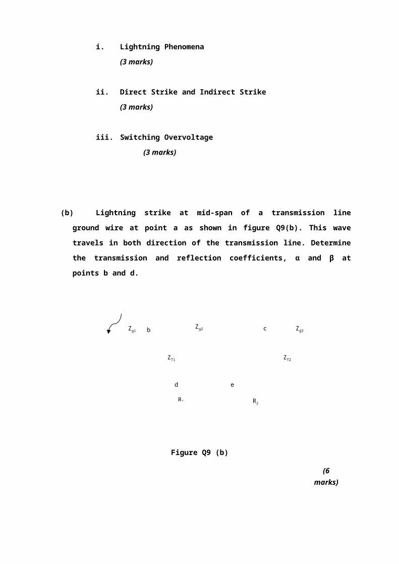
Voltage at the top of tower 1
¿V 1+V 2+V 3+…
¿ β1u( t)'+βT αR β1u(t )' '+αR2 βT β1 αT u (t) ' ' '
¿0.4u (t) '+(1.225)(−0.28)(0.4)u(t) ' '+(−0.280)2(0.4)(1.225)(−0.28)u(t )' ' '
u(t )=I (t)Z eq=30 X 225
¿6.75 MV=1 p .u .
(without Z lightning channel)
u(t )’=I (t)Z eq /¿Zlightningchannel
¿30 X 195.7
¿5.87 MV .
Graphical Representation.


CHAPTER 4
Question 1:
a) What is the basic difference between self-restoring and non self-restoring insulation?
b) Briefly explain, with the aid of suitable diagrams, the statistical method of insulation
coordination.
c) In a laboratory, switching impulses are applied to a post insulator in order to
determine the basic switching impulse insulation level (BSL) of the post insulator.
The results of the test are shown in Table Q1. These test results are then plotted on
a linear graph paper as in Figure Q1.
i) Determine the critical flashover voltage (CFO)
ii) Calculate the BSL using statistical equation
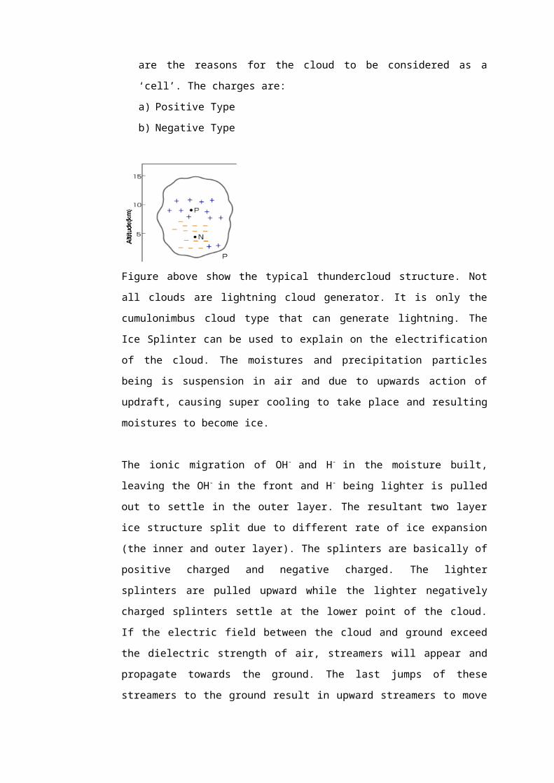
iii) Show in the graph of Figure Q1 the value of BSL, and what is the percentage of
flashover at this condition?
Table Q1
Applied crest voltage, kV
No. of "shots"
No. of "flashovers
900 100 21000 40 201050 40 331075 100 93960 40 7980 40 16960 40 10
850 900 950 1000 1050 11000
20
40
60
80
100
Applied crest voltage, kV
No.
of "
flash
over
s
Figure Q1
Answer Q1:
a) Self-Restoring (SR) Insulation
- Insulation that completely recovers insulating properties after a disruptive
discharge (flashover) caused by the application of a voltage is called self-
restoring insulation.
- This type of insulation is generally external insulation.
Non Self-Restoring (NSR) Insulation

- This is the opposite of self-restoring insulators, insulation that loses insulating
properties or does not recover completely after a disruptive discharge caused
by the application of a voltage.
- This type of insulation is generally internal insulation.
b) The aim for statistical method is to quantify the risk of failure of insulation through
numerical analysis of the statistical nature of the overvoltage magnitudes and of
electrical withstand strength of insulation.
In a statistical study, what has to be known is not the highest overvoltage possible,
but the statistical distribution of overvoltage.
The risk of failure of the insulation is dependent on the integral of the product of the
overvoltage density function fo(V) and the probability of insulation failure P (V). Thus
the risk of flashover (R) per switching operation is equal to the area under the curve.
R=∫0
∞
f o (V ) .P .dV
Since a suitable insulation cannot be found such that the withstand distribution does
not overlap with the overvoltage distribution, in the statistical method of analysis, the
insulation is selected such that the 2 % overvoltage probability coincides with the 90
% withstand probability as shown.
c)

i) CFO is defined as a voltage level at the condition of the insulation results in a
50 % probability of flashover, i.e, half the impulse flashover. Therefore, from
figure Q1 we can determine the CFO = 1000 kV.
ii) BSL=CFO(1−1.28σ
CFO )=1000(1−1.2850
1000 ) = 936
Therefore, BSL = 936 kV
Where σ is the voltage difference between the 16 % and 50 % points or
between the 50 % and 84 % points. From the Figure Q1, σ = 50 kV.
iii)
850 900 950 1000 1050 11000
20
40
60
80
100
Applied crest voltage, kV
No.
of "
flash
over
s
Therefore, the percentage of flashover at BSL is 10 %
10%
936

Question 2:
a) Fig. Q4 (a) shown an insulation coordination practice using gaps/arcing horns. Briefly
describe what you understand from the diagram.
Fig. Q2(a) Coordination using gaps/arcing horns
b) Fig. Q2(b) shown an evaluation of risk factor in an insulation coordination practice using
the statistical technique. Briefly describe what you understand from the diagram as Fo
(V) and P(V) move to Either direction (left and right).
c) A 500 kV steep fronted wave (rate of rise 1000kV/µs) reaches a transformer of surge
impedance 1500 Ὠ through a line surge impedance 500 Ὠ and protected by a lightning
Transformer insulation
1.0m line gap/arcing horns
0.66 mm co-ord gap

arrester with a protective level of 700 kV, 60 m from the transformer. sketch the voltage
waveforms at the arrester location. Determine the time at which the arrester operates.
Assume all waves travel at 3.0 x 10⁸ m/s
Fig.Q4 (b) Evaluation of risk factor
Answer Q2:
a) Consider the typical co-ordination of a HV transmission line between the transformer
insulation. A line gap ( across an insulator string) and a co- coordinating gap ( across the
transformer bushing), in a rural distribution transformer, a lightning arrester may not be
used on account of the high cost and a coordinating gap mounted on the transformer
bushing maya be the main surge limiting device. In co-coordinating the system under
consideration, we have to ensure that the equipment used is protected, and that
inadvertent interruptions are kept to a minimum. The co-coordinating gap must be chosen
so as to provide protection of the transformer under all conditions (slow as well as fast
front waves). However, the line gaps protecting the line insulation can be set to a higher
characteristic to reduce unnecessary interruptions. A typical set of characteristics for
Lower overvoltage
Overvoltage Distribution
fo (V)
P(V)Insulation withstand distribution
Higher insulation
fo (V) .P (V)
Risk of failure
90% withstand probability
2 % overvoltage probability
Voltage
Probability (%)

insulation coordination by conventional methods, in which lightning impulse voltages are
the main source of insulation failure, is shown in the above figure. For the higher system
voltages, the simple approach used above is inadequate. Also, economic considerations
dictate that insulation co-ordination be placed on a more scientific basis.
b) The aim of statistical methods is to quantify the risk of failure of insulation through
numerical analysis of the statistical nature of the overvoltage magnitudes and of
electrical withstand strength of insulation. The risk of failure of the insulation is
dependent on the integral of the product of the overvoltage density function fo(V) and
the probability of insulation failure P(V).Thus the risk of flashover per switching
operation is equal to the area under the curve ∫ fo (V) *P(V)*dV, as shown in the
diagram. Since we cannot find suitable insulation such that the withstand distribution not
overlap with the overvoltage distribution, in the statistical method of analysis, the
insulation selected such that the 2 % overvoltage probability coincides with the 90 %
withstand probability shown.
c)
500kVpeak α
Z0=500ὨD=60m β ZT=1500Ὠ
Arrester
If the separation is 50 m, the travel time in the line ( Between arrester and transformer)
τ =60
100
=0.2µs
Transimision and reflection coefficients
β =2 X 1500
1500+500
=1.5
α =1500−5001500+500
=0.5

Question 3:
a) A transformer has an impulse insulation level of 1175 kV and is to be operated with an
insulation margin of 15% under lightning impulse conditions. The transformer has a
surge impedance of 1600 and is connected to a transmission line having a surge
impedance of 400 . A short length of overhead earth wire is to be used for shielding
the line near the transformer from direct strikes. Beyond the shielded length, direct
strokes on the phase conductor can give rise to voltage waves of the form 1000e−0.05 tkV
(where t is expressed in µs).
If the corona distortion in the line is represented by the expression,
Δtx= 1
B [1−VoV ]
Where B = 110m/µs and Vo = 200kV, determine the minimum length of shielding wire
necessary in order that the transformer insulation will not fail due to lightning surges.
b) A 500kV steep fronted wave (rate of rise 1667kV/µs) reaches a transformer of surge
impedance 1600 through a line of surge impedance 400 and protected by a
lightning arrestor with a protective spark-over level 700 kV, 75 m from the transformer.
Sketch the voltage waveforms at the arrestor location. Determine the time at which the
arrestor operates. Sketch also the voltage waveforms at the transformer location.
Determine the maximum voltage at the transformer and the duration it appears across
the transformer. Assume the surge travels at 300 m/us in the line and no reflection is
considered at the arrester.

Answer Q3:
a)
1000e−0.05 t α
Z0 =400 Ω β ZT=1600Ω
β = 2 X 1600
1600+400
= 1.6For BIL of 1175 kV, and an insulation margin of 15%, the maximum permissible voltage
= 1175 X85
100
= 998.75 kVSince the voltage is increased by β = 1.6 times at the terminal equipment (transformer),
the maximum permissible incident voltage must be decreased by this factor, hence the
maximum permissible incident voltage is
= 998.75
1.6= 624.22 kVTherefore the shielding wire must reduce the surge to 624.22 kV (by virtue of the corona
distortion), that is
1000e−0.05 t=624.22
t = 9.425 µs
Hence Δt = 9.424 µs
The corona distortion is given by
Δtx= 1
B [1−VoV ] µs/m

Substituting
9.425x= 1
110 [1− 2006.24 .22 ] µs/m
X = 1525.53 m
Therefore the minimum length of shielding wire required = 1.526 km.
b)
500kV peak α
Z0 =400Ὠ ZL = 75m β ZT=1600Ὠ
Arrester
If the separation is 75m, the travel time in the line
τ = 75
300
= 0.25 µs
Transmission and reflection coefficients
β = 2 X 1600
1600+400
= 1.6
α = 16500−4001600+400
= 0.6

From the diagram, arrester operates at t = 0.7 µs
Then, the maximum voltage across the transformer = 800kV
So, the duration of this voltage across the transformer = 0.4 µs
0
Reflected surge
Time (µs)
(0.6 x 1667 = 1000 kv/µs)
Resultance voltage across arrestor
Max votage of TransformerArrestor operates at 700kv (spark over)
Arrestor voltage (kv)
200
400
600
800
0.1 0.2 0.3 0.4 0.5 0.6 0.7 0.8 0.9 1.0 1.1ך ך
0
Transmitted surge
Time (µs)
(1.6 x 1667 = 2667 kv/us)
Transfomer operating time 0.95 µs
Arrestor operates at 0.7 us + 0.25 µs ( at tx )
Arrestor voltage (kv)
200
400
600
800
0.1 0.2 0.3 0.4 0.5 0.6 0.7 0.8 0.9 1.0 1.1

Question 4:
a) What is the basic difference between self-restoring and non-self restoring insulation?
Describe a method for the implementation of insulation coordination to a power system
with self-restoring and non-self restoring insulation. In each case emphasis should to be
given to the description of Risk Failure and Critical flashover Voltage V50.
b) Describe the differences between Basic Lightning Impulse Insulation Level (BIL) and
Basic Switching Impulse Insulation Level (BSL) and explain how they affect in the design
of power system networks?
The following results are obtained for the determination of volt-time curve obtained for a
non-self restoring and self-restoring insulation in a multi-level test.
Table 4c (i) The volt-time curve characteristic of string insulator
Voltage level
(kV) 1300 1600 2280 2600 2800 2900 3000
No. of impulses
applied to the
insulator10 10 10 10 10 10 10
Time to flash
(μsec) 35 30 20 15 10 5 2
Table 4c(ii) The volt-time curve characteristic of a pair of arc-horn
Voltage level
(kV) 1200 1880 2800 3100 3300 3400 3500
No. of impulses
applied to the
insulator10 10 10 10 10 10 10
Time to flash
(μsec) 35 30 20 15 10 5 2
Answer the following questions:
(i) Based on the above volt-time curve of the Table 4c(i) and 4c(ii)
(ii) Can the arc-horn I protects the string insulator I against destructive
discharges?

(iii) If the flashover voltage of the arc-horn I is reduced by 20% while maintaining
same time to flashover, is the volt-time curve of arc-horn I suitable for insulation
coordination with the string insulator I? Give reasons.
If the volt-time curve from Table 4c(i) and 4c(ii) respectively is used for the line
insulation coordination, will there be a destructive discharge if a lightning surge with a
peak of 2000 kV at 1.5μsec and afterwards decrease linearly to zero at rate of 20 kV per
μsec, arrived at the string insulator point of connection with the conductor? If yes, where
will be the discharge takes place?
Answer Q4:
a) The basic difference between self restoring and non-self restoring insulation is:
Self-Restoring Insulation: Insulation that completely recovers insulating properties after
a disruptive discharge (flashover) caused by the application of a voltage is called self-
restoring insulation. This type of insulation is generally external insulation.
Non-Restoring Insulation: Insulation that losses insulating properties after a disruptive
discharge (flashover) caused by the application of a voltage. This type of insulation is
generally internal insulation.
Critical Flashover Voltage (CFO)
CFO is defined as a voltage level at the condition of the insulation results in a 50%
probability of flashover, i.e., half the impulses flashover.
Method of describing the risk of failure.
1. Over voltage distribution–Gaussian function.
2. Insulation breakdown probability–cumulative distribution
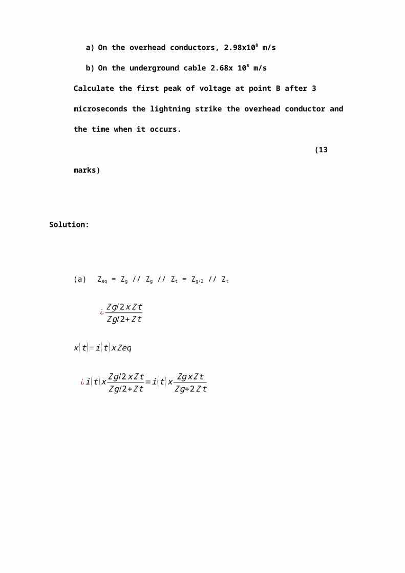
R=∫0
∞
Pb (Vk ) p ο(Vk )δu
Insulation strength characteristic for non
Self-restoring insulation

Insulation strength characteristic for
self restoring Insulation
BIL=CFO¿)
BSL=CFO(1−1.28σf
CFO )
b) For equipment rated at less than 300 kV, it is a statement of the Basic
Lightning Impulse Insulation Level (BIL) and the short duration power frequency
withstand voltage. For equipment rated at greater than 300 kV, it is a statement of the
Basic Switching impulse Insulation Level (BSL) and the power frequency withstand
voltage.
Spark gaps for surge protection
The selected gap spacing should no only be capable of withstanding the highest normal
power frequency voltage but should flash-over when over voltages occur, protecting the
equipment. However, this is not always possible due to the voltage-time characteristics
gaps and equipment having different shapes. Rod gaps are generally used as a form of
back up protection rather than the main form of protection.
Surge Diverters
Surge diverters (or lightning arrestors) generally consist of one or more spark gaps in
series, together with one or more non-linear resistors in series. Silicon Carbide (SiC) was
the material most often used in these nonlinear resistor surge diverters. However, Zinc
Oxide (ZnO) is being used in most modern day surge diverters on account of its superior

volt-ampere characteristic. In fact the ZnO arrestor is often used gapless, as its normal
follow current is negligibly small.
(i) No.
(ii) The new volt-time curve of the arc-horn I is suitable for the protection of the
string insulator I. This is true when the volt-time curve of arc-horn I lies lower
than the string insulator I.
(iii) Destructive discharge will take place. It will happen on the string insulator I.
Question 5:

a) Briefly discuss the implementation of insulation coordination for high voltage
transmission line system using statistical method?
b) Explain the differences between the insulation of a high voltage system and low voltage
system. Confine your explanation to a transmission line entering a high Voltage
substation substation whereas for the low voltage system confine to the AC mains point
entry in a house to the electrical and electronic equipment.
c) A test was conducted on a pair of arc-horn that was used for transmission line for the
Protection of string glass insulator against the lightning inducing effect on phase
conductor. This test is important because Malaysia is in the region of high isoceraunic
level where in every second there is not less that 100 flash to the ground. Before the
installation of the string insulator, lightning impulse tests are carried out in a high voltage
laboratory to determine the BIL and BSL. The results of BIL tests are shown in Table 5c
and the test set up is shown in Fig 6. Determine the BIL of the string insulator.
Table 5c: Results of lightning impulse test of a 12-unit string insulator where NO means
NO FLASHOVER and YES mean FLASHOVER
Kv\N
(injection)
1 2 3 4 5 6 7
700 NO NO NO NO NO NO NO
750 NO NO NO NO NO NO NO
800 NO YES NO NO NO NO NO
820 YES YES YES NO NO NO YES
840 NO YES YES YES YES YES NO
850 YES YES YES YES YES YES NO
860 YES YES YES YES YES NO YES
870 YES YES NO YES YES YES YES
880 YES YES YES YES YES YES YES
890 YES YES YES YES YES YES YES
S Rf
ClRtCi

Fig 5 The schematic diagram of an impulse generator where Rf is the front resistor, Rt is
the tail resistance, C1 is the load capacitance and Ci is generator capacitor.
Answers Q5:
a) Statistical Method
This is based on knowledge of the statistics of both overvoltage occurrence and of
flashover probability. The design is based on an acceptable risk of flashover. If at a
voltage level v, the probability of failure is P(v) and the frequency of occurrence if surge
of that level is f(v) then the risk of function is defined as,
r (v )=P (v ) f (v)
The risk function is shown below,
For a given insulation design, the total risk of failure will be,
R∫0
∞
P (v ) f (v )dv
The risk is R is therefore determined by the area under the r(v) curve, as the insulation
is strengthened by using a large gap or layer insulation.
Figure 5

For a given insulation design the total risk of failure will be
R∫0
∞
P (v ) f (v )dv
The risk R is therefore determined by the meas under the r(v) curve as the insulation is
strengthened (e.g by using a layer gap or longer insulation string), so this risk at failure
shall reaches.
The effect of increasing, Vg on the risk of failures. It is therefore possible to press the
P(v) curve, we can then choose a reference probability and quote the voltage as a
statistical withstand voltage Vw.

The peak value of a switching or lightning impulse test voltage at which insulation
exhibits, under the specified conditions, a 90% probability of withstand has a 10%
probability of breakdown.
b) The system design engineer will therefore specify that the insulation must have a
withstand voltage of Vw, based on the acceptable risk criterion, and the insulation
design engineer will develop insulation suitable for what withstand level.
Line insulation coordination.
1. The tower strike distance or clearance between the phase conductive and the
grounded tower sides and upper tress.
2. The insulator string length.
3. The number and type of insulation.
4. The need for and type of supplemental lower grounding.
5. The phase to ground midiper clearance.
6. The phase strike distance or clearance.
7. The need for rating and location of line surge arrestable.
c) Insulation coordination in line voltage, installation and equipment. The classification of
expected overvoltages in 230/400V consume installation resulted in the following fault
categories. The worst case is considered is the transient overvoltages occurs at the
peak of the surge voltage.
Category J: Sites that are protected a transient overvoltage’s.
Category II: Sites at which external overvoltages are not expected.
Category III: sites of category II at which particular demands are made for reliability
and availability .

Category IV: sites at which external overvoltages as especial.
CFO = 826.0 kV
σ=27.5kV
Applied Crest Voltage, kV
Kv\ N( injection) Proability of breakdown (%)
700 0
750 0
800 1/7 ×100 = 143%
820 4/7 ×100 = 67.14%
840 5/7 ×100 = 71.4%
850 6/7 ×100 = 85.7%
860 6/7 ×100 = 85.7%
870 6/7 ×100 = 85.7%
880 7/7 ×100 = 100%

890 7/7 ×100 = 100%
BIL=CFO (1−1.28σf
CFO ) ¿826 (1−1.28
27.5826 )
¿826 (1−0.0426 )
¿826× 0.957
¿790.5kV
The BIL of the string insulator is 790.5 kV
650 700 750 800 850 900 9500.00%
20.00%
40.00%
60.00%
80.00%
100.00%
120.00%
0.00% 0.00%
14.30%
67.14%71.40%
85.70%85.70%
85.70%
100.00%100.00%
Proability of breakdown (%)
Kv\ N( injection)
Proa
bilit
y of
bre
akdo
wn
(%)
Question 6:
a) What is the basic difference between self-restoring and non-self-restoring insulation?
b) Describe the differences between Basic Lightning Impulse Insulation Level (BIL) and
Basic Switching Impulse Insulation Level (BSL) and explain how they affect in the
design of power system network?
Following results were obtained for a self-restoring insulation in a multi-level test.
Voltage level (kV)
200 210 220 230 240 250
No. of impulse applied
10 10 10 10 10 10
No. of Flashovers

0 1 5 9 10 10
c) Determine the following:
(i) 50% flashover
(ii) P U standard deviation
(iii) Statistical withstand voltage
(iv) Statistical flashover voltage
(v) BIL of this insulation.
Answer Q6:
a) Self-restoring insulation regains its dielectric integrity following the occurrence of a
breakdown. The examples are gas or liquid insulations. Non-self-restoring insulation
losses its insulating property after a breakdown or disruptive discharge and must be
replaced. Solid insulation, as in cables, transformers, and machines, belongs to this
category of insulation.
b) BIL: This is the reference insulation level which is expressed as peak impulse voltage
having a standard lightning impulse waveform of 1.2/50 μsec. It is determined by tests
made using impulses of the standard lightning impulse wave shape.
BSL: Similar to BIL but is defined for a standard switching impulse voltage of 250/2500
μsec waveform. It is generally specified for equipment with rated voltage at >= 300
kVrms.
The level of voltage supply from customer side to the generation side can be
categorized as
i) Low Voltage (LV)
ii) Medium Voltage (MV)
iii) High Voltage (HV)
iv) Extra High Voltage (EHV)
v) Ultra High Voltage (UHV)
These systems are affected by transient overvoltage generally due to external source
such as lightning phenomenon and internally generated is the switching activities. In
order system components can function as they should, they have to be design to
withstand against lightning related surges as well as switching activities. Related to

withstand on lightning surge BIL is to be referred and BSL for switching. System working
more than 300kV BSL is more significant than BIL.
(c)
i) 220kV
ii) P = 16%, V = 211.2kV
P = 84%, V = 228.1kV
Standard Deviation = V50 – V16 = 220 – 211.8 = 8.2kV
Standard Deviation = V84 – V50 = 228.1 – 220 = 8.1kV
Coefficient of variation = 8.1/220 = 0.037 pu
iii) Statistical withstand voltage
= (1 – 3 Coeff)V50
= (1 – 3*0.037)*220
= 195.6kV
iv) Statistical flashover voltage
= (1 + 3 Coeff)V50
= (1 + 3*0.037)*220
= 244.4Kv
200 210 220 230 240 250 2600
10
20
30
40
50
60
70
80
90
100
Breakdown Voltage (kV)
Perc
enta
ge (%
)
84%
16%

Question 7:
a) Discuss three (3) mechanisms of solid insulation breakdown.
Answer Q7:
1. Intrinsic Breakdown
When the high voltage applied for a long time.
Electrical power is determined by the intrinsic strength.
Depend on the presence of free electrons that move through the lattice of
solid.
These electrons produce a current flow.
2. Electromechanical Breakdown
Less rigid insulation material (rubber, PVC).
Electrostatic forces that act exceed the strength of solid mechanics.
Mechanical damage will occur.
3. Thermal Breakdown
Leakage current flow when the electric stress applied.
Solid temperature increased by the heating process.
Heat transferred to the insulation surroundings by conduction and radiation
process.
Limiting the maximum thickness of a solid.
4. Chemical And Electrochemical Breakdown
Chemical changes if the electrical stress is continuously react with air and
gas.
Reactions that occur - oxidation, hydrolysis, chemical reaction.

Can be reduced by checking the material carefully.
5. Treeing And Tracking Breakdown
Two effects when electric stress is long:
i. the presence of conductive path across the surface.
ii. effects of leakage current due to sparks through the path that
produces sparks.
During the process oftracking,the spread ofsparksin the form
ofbranchescalledtreeing.
6. Internal Discharge Breakdown
Cavitycontains airinthe solidinsulation.
Fieldin the cavity larger than the field in theinsulation.
Breakdown exists in the cavity.
Question 8 :
a) Explain what is meant by the B.I.L of a high voltage equipment.
Answer Q8:
a) For equipment rated at less than 300 kV, it is a statement of the Basic Lightning Impulse
Insulation Level (BIL) and the short duration power frequency withstand voltage.

Question 9 :
a) Describe in details with the appropriate diagrams, the methods of insulation coordination
for over voltages.
b) In transmission system, components whose failure would have very severe
consequences are often protected by protective devices. Describe the coordination of
protected insulation with regards to a high voltage transformer.
Answer Q9:
a) There are two methods of insulation coordination for overvoltages:
i) Conventional Method.
This is the method used when the probability of failure for a given overvoltage is
unknown, ie. With non-self restoring insulation. The known probability distribution of
overvoltage amplitudes is used only to determine the maximum surge which is liable
to occur. To this is added a safety margin to allow for the unknown flashover
probability distribution. The resultant voltage level is specified as a ‘withstand’
voltage, V w which the insulation must be able to hold off.
ii) Statistical Method
This is based on knowledge of the statistics of flashover probability. The design is
then based on an acceptable risk of flashover. If at a voltage level V, the probability

of failure is P(V) and the frequencies of occurrence or surges of that level is f(V) then
the risk function is defined as, r(V) = P(V).f(V).
The risk function is shown below,
For a given insulation design the total risk of failure will be:
∫0
∞
P (V ) .F (V )dV
The risk is therefore determined by the area under the r(V) curve. As the insulation is
strengthened by using larger gap or longer insulation strength, the risk of failure
diminishes as in the diagram below.

For a chosen risk of failure it is therefore possible to position the curve. We can then
choose a reference probability and quote the corresponding voltage as a statistical
withstands voltageV w. In practice the reference probability is normally taken as P(V)
= 0.1, ie. V w is the voltage at which the insulation has a 90% probability of withstand.
The system design engineer will therefore specify that the insulation must have a
withstand of V w based on the acceptable risk criterion, and the insulation design
engineer will develop insulation suitable for that withstand level.
b) In transmission systems, component whose failure would have very severe
consequences are often protected by devices such as surge diverters or spark gaps.
These devices are designed to break down in preference to the insulation of the
equipment to be protected such as high-voltage transformer. The coordination of the
protective devices insulation with regards to the protected equipment can be made by
using the conventional and statistical methods. In applying the conventional method, the
maximum allowable overvoltage is coordinated with the protective level of the device, ie.
The protective device is set to flashover if V w for the more expensive equipments is
exceeded.
In applying the statistical method the flashover probabilities Pp(V) and P(V) of the
protective device and the equipment which it protects are used to calculate a probability

P*(V) that the main insulation will flash over in spite of the protective device. The risk is
then found form R*=∫0
∞
P∗(V ) .F (V )dV
If the protective device is a spark gap, it itself will be dimensioned by normal methods to
give a risk of flashover which although greater than other devices, is still limited. If surge
diverters are used there is no reason to limit the risk of flashover as surge diverters
automatically restore the system voltage due to their non-liner resistance characteristics
without damage. However if a surge diverter is triggered by a high-voltage switching
surge or lightning transient.
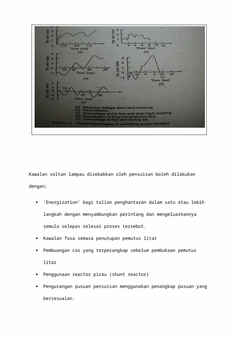
Question 10:
(a) Describe the secondary processes which can lead to an electron avalanche and how
these processes may be identified. Show that the discharge current in a multi avalanche
Townsend process in a non-attaching gas is given by
I=I 0 eαd
1−γ [e¿¿(αd−1)]¿
Where I 0 – initial voltage
Α – first Townsend ionization coefficient
γ - Second Townsend ionization coefficient
d – Gap distance in cm
(b) Measurement of breakdown voltages in a uniform field spark gap in air gave the result as
shown in the Table Q10
Table Q10
Gap spacing (mm) Pressure (Bar) Temperature (C ˚)Breakdown voltage,
V s(kV )
2.5 1.03 30 0.91
27 1.18 15 88.38
Use the expression derived from Paschen’s law V s=A (pd )+B (√ pd ) determine
i) The relative air densityρ, referred to standard atmospheric conditions of 1013.25
mbar and 20˚C.
ii) The value of constant A and B.
iii) The breakdown voltage of a 3cm gap spacing at pressure of 3000 mbar and a
temperature of 20˚C.

Answer Q10:
a) The electrical breakdown of a gas is brought about by various processes of ionization.
These gas processes involving the oscillation of electrons, ions and photons with gas
molecules and electrode processes which take place at or near the electrode surface.
When a pair of electrodes is immersed in a gas and a voltage applied across them the
current voltage characteristics of figure below is observed
At low voltage the observe current is due to collection of free carriers in the gap and as
the voltage is increased a level is reached at which the free electrons gain enough
energy to ionize. Electrons produced may cause further ionization so that an electron
avalanche is generated. Ionization is the process by which an electron is removed from
an atom, leaving the atom with a net positive charge. The probability of ionization due to
the electron will depend on the number of collision made per unit distance with
coefficient referred as the primary ionization coefficient which is the number of ionization
collisions per unit electron per cm travel. With the primary ionization alone the
discharged is not self sustaining. If the source of initial electrons is removed the current,
the current I falls to zero. This suggests that processes other than simple α - process are
occurring. This additional current is produced by secondary emission processes. A
secondary ionization coefficient γ is defined as the number of secondary electrons
produced at the cathode produced in the gap
These processes for secondary electrons liberation can be identified by:
i) Positive ion γ i- ions do not have enough energy to ionize gas molecules directly but
may release electrons on colliding with the cathode surface
I
Breakdown
Non-Self-sustain
Self-sustain
VVs
Ionization
Charge collection
Io
INon-Self-sustain S
elf-sustain
Vs
Ioniz
Charge
Io
I

ii) Photons γ p- a proportion of the collision in the gap cause excitation of neutral gas
molecules which in return to the ground state may be emit photons which release
electrons by photoemission.
iii) Metastablesγ p- metastables molecules may diffuse to the cathode and release
electrons
One or more secondary mechanism may exist giving a total secondary effect
described
γ=γ p+γ p+γ p
Let n0 = number of initials electrons at cathode
n0' = The number of secondaries
n0' '= the total emission including secondaries
i.e n0' '=n0+n0 '
At x ,n ( x )n=nο e ^ (αx)
The total number of new electros produced, n (d )=nο ( e ^ (αd-1)
dx
n0
Volts
Distanceo d
- +

If γ electrons are produced at the cathode per ionizing collision in the gap, then
nο '=γnο ( e ^ ( αd - 1)
Thus, nο = nο + γnο (e(αd−1) )¿
nο = nο over 1 - γ ( e ^ ( αd - 1) ^ <?> )¿
∴n (d )=nο e ^ ( αd ) = nο e ^ ( αd ) over 1 - γ ( e ^ left (αd - 1 right ) )
Under steady state conditions, I=Iοe(αd )
1−γ (e (αd−1))
Gap spacing (mm) Pressure (Bar) Temperature (C ˚)Breakdown voltage,
V s(kV )
2.5 1.034 30 0.91
27 1.180 15 88.38
d1=0.25cm=10mBar , t=30 ˚C ,V s=0.90kW
f 20=P
1013−273+20
273+ t
¿ 10341013
.293288
=1.19
Question 11:
a) What is the basic different between self-restoring and non-self-restoring insulation?
b) Describe the differences between Basic Lightning Impulse Insulation Level (BIL) and
Basic Switching Impulse Insulation Level (BSL)
c) Name the types of BIL that are mentioned in the standards?

(How many type of Basic Lightning Impulse Insulation Level and name them?)
d) Name the types of BSL that are mentioned in the standards?
(How many type of Basic Switching Impulse Insulation Level and name them?)
e) In relation to BIL and BSL, standards provide two types of tests to determine the best
method to obtain BIL and BSL.
(i) Explain those methods as provided by the standards document.
(ii) Discuss which method is the best by not neglecting to discuss points for instance
probability of passing test, probability of flashover per-impulse, manufacturer’s risk
and ideal test and other relevant factors.
Answer Q11:
a) Self-Restoring Insulation : Insulation that completely recovers insulating properties after
a disruptive discharge (flashover) caused by the application of a voltage.
Non Self -Restoring Insulation : Insulation that losses insulating properties after a
disruptive discharge (flashover) caused by the application of a voltage.
b) For equipment rated at less than 300 kV, it is a statement of the Basic Lightning Impulse
Insulation Level (BIL) and the short duration power frequency withstand voltage. For
equipment rated at greater than 300 kV, it is a statement of the Basic Switching impulse
Insulation Level (BSL) and the power frequency withstand voltage.
c) 2 type, statistical and conventional
d) 2 type, statistical and conventional
e)
i) 1) The n/m test : m impulses are applied. The test is passed if no more than n result
in flashover.
2) The n + m test : n impulses are applied. If none result in flashover, the test is
passed. If there are two or more flashover, the test is failed. If only one flashover
occurs, m additional impulses are applied and the test is passed if none of these
result in a flashover.
ii) These alternate tests can be analysed statistically to determine their characteristic.
That is a plot is constructed of the probability of passing the test as a function of the

actual but unknown probability of flashover per application of a single impulse. The
characteristics for the above three tests are shown in Fig 1.1
Question 12:
a) Discuss three (3) mechanisms of solid insulation breakdown
b) Show that the breakdown criterion in gas according to Paschen’s Law is given
by :
g¿¿¿
where, d s- gap distance at sparkover voltage
p-pressure

V s - sparkover voltage
f&g-different functions
c) In nitrogen gas, the static breakdown voltage V s of a uniform field gap may be
expressed as,
V s=Apd+B √ pd
Where A and B are constants, p is the gas pressure in torr referred to a temperature of
20 ° and d is the gap legth in cm.
A 1 cm uniform field gap in nitrogen at 760 torr and 25 ° is found to breakdown of 33.3
kV. The pressure is then reduced and after a period of stabilization, the temperature and
pressure are measured as 30 °C and 500 torr respectively. The breakdown voltage is
found to be reduce to 21.9 kV. If the pressure is further reduced to 350 torr while the
temperature of the closed vessel is raised to 60 ° and the gap distance is increased to 2
cm, determine the breakdown voltage.
Answer Q12:
a) Three (3) mechanisms of solid insulation breakdown :-
i) Intrinsic/Ionic breakdown
ii) Electromechanical breakdown
iii) Thermal breakdown
Intrinsic/Ionic breakdown.
Occurs at a very short duration of HV applied (10-8 s).
Depends on the presence of free electron, which capable of migration thru the lattice
of the dielectric.
G CREATIVE AND INNOVATIVE MIND

Electromechanical breakdown.
Due to electrostatic compressive forces that exceed mechanical compressive
strength.
The highest apparent electric stress before breakdown, if the thickness of specimen
do
is compressed to d under applied HV;
Mechanical instability occurs when d/do = 0.6, and Y : Young’s modulus and
depends on mechanical stress.
Thermal breakdown
Conduction current flows – heats up the specimen and the temperature rises.
Heat generated transfers to the surrounding medium by conduction and radiation.
Breakdown occurs when heat generated > heat dissipated.
Heat generated is proportional to the frequency – thermal breakdown is more serious
at high frequency.
Thermal breakdown stresses are lower under a.c. condition then d.c.

b) By neglectingattachment, breakdown criterion;
γ (ead−1 )=1…………… (1)
Since (Paschen’s Law) ,αp=f ( E
p) and γ=g (E
p) where f &g signify different function.
At breakdown, α ds=pd f (E s
p)………………. (2)
= pds f (V s
pds
)…….……….... (3)
Substitute (2) &(3) into (1) gives
g( V s
pds)exp[ pd s . f ( V s
pds)]−1=1proved
c) V s1=Ap1 d1+B √ ( p1 d1) p1=760 torr ,t 1=25 ˚ C ,d1=1cm ,V s1=33.3kV
Corrected pressure to standard temperature of 20 ˚ C,
p1=760(273+20)
273+25=747.25 torr √ p1 d1=27.3
33.3=A (747.25 ) (1 )+B (27.43 )(1)
¿747.25 A+27.34 B…….(1)

V s 2=Ap2 d2+B √( p2 d2) p2=500 torr ,t 2=30 ˚ C ,d2=1cm ,V s 2=21.9kV ,
Corrected pressure to standard temperature of 20˚C
p1=500(273+20)
273+30=483.50 torr ,√ p2d2=21.99
21.9=A (483.50 ) (1 )+B (21.99 )(1)
¿483.50 A+21.99B……………..(2)
(1 )×21.99 :732.27=16432.03 A+601.21B………(3)
(2 )×27.34 :598.75=13218.89 A+601.21B…...….(4)
(3)-(4):13352=3213.14 A A=0.042∧B=0.072
V s 3=Ap3 d3+B √( p3d3) p3=350 torr , t 3=60 ˚C ,d3=2cm ,V s 3=?
Corrected pressure to standard temperature of 20 ˚ C,
P3=350(273+20)
273+60=307.96 torr ,√ p3 d3=24.82
V s3=(307.96 ) (2 ) (0.042 )+ (24.82 )(0.072)
=27.66kV

CHAPTER 5
INSULATION DIAGNOSTIC & PARTIAL DISCHARGES
(QUESTION AND ANSWER)
Question 1
a) The dissipation factor or loss tangent is an indication to determine the performance of
insulating property of insulators. The most common method used to determine the lost
tangent is by using a.c bridges.
i) Sketch the circuit diagram of a high voltage Schering bridge for the
measurement of loss tangent (tan δ).
ii) Derive the expression for tan δ of the unknown series model of tge tested
sample when the high voltage standard capacitor used in the Schering Bridge is
a loss-free type.
Answer
i)

C : Capacitance of the sample
r : Resistance of the sample
C2 : Standard capacitor
R3 , R4 and C4 : Variable components of Schering bridge
ii)
Z1=r− jωC
; Z2=1
jωC2
; Z3=R3 ;Z4=R4
1+ jωC4 R4
AC Supply
Sample
C4R4R3
r
C2
C

At balance condition ; Z1 Z 4=Z2 Z3 ;
Z1=Z2 Z3
Z4
=[ R3
jωC2] [ 1+ jω C4 R4
R4]= − j R3
ωC2 R4(1+ jωC4 R4 )
Z1=r− jωC=
C4 R3
C2
− jR3
ωC2R4
By equating the real and imaginary parts of both side;
Therefore;
r=C4 R3
C2
;∧C=C2 R4
R3
For series model, tan δ = 𝝎Cr,
tan δ=ω(C2 R4
R3)(C4 R3
C2)=ωC4 R4
b) Breakdown in solid or liquid dielectrics arise from the action of the electrical discharges
in internal gaseous cavitties. Draw an equivalent circuit for such an arrangement and
derive the expression for energy dissipated in the cavity in one discharge.
Answer

Void in solid dielectric material Equivalent circuit of void in the structure
a
b2
b1
c tVaT
void
Cc
Cb
CaVa

Cb=ε0 εr A1
T−tC c=
ϵ 0 A1
t
Energy dissipated in the cavity in one discharge;
¿12 (C c+
CaCb
Ca+Cb )V c ²
Where
V c=Cb
Cb+Cc
∙V a
Therefore
¿12 (C c+
CaCb
Ca+Cb )( Cb
Cb+C c ) ² V a ²
¿12 (Cb²
Cc )V a²
c) A solid dielectric specimen of 5cm diameter and 10mm thickness has dielectric
constant of 3. It has an embedded air filled void of 2.5mm diameter and 1mm
thickness. It is subjected to a voltage of 100k Vrms. Find the voltage at which an
internal discharge in the void can occur. The breakdown strength of air is 3kV/mm. Also
determine the charge value each time there is discharge inside the void and what will
be the value of charge as measured on the detector?
Answer
The inception voltage of the stressed void Vi is given by:

V i=Ecb t(1+ 1εr(d /t−1))
Where
Ecb - breakdown stress of the void = 3 kV/mm
d - thickness of the specimen = 10mm
t - thickness of the void = 1mm
ε r - dielectric constant of the specimen = 3
when t = 1mm
V i=3∗1(1+ 13(10/1−1)) = 12kV peak
Capacitance of void
C c=ε0 εr A
t
When t = 1mm, area of void = π (2.5 x 10ˉ³)² / 4 = 491 x 10ˉ⁶ m²
C c=(8.854 x 10ˉ ¹²)(1)(491 x10 ˉ ⁶)
1x 10 ˉ ³=4.34 x10 ˉ ¹⁴ F
Capacitance of slab
Ca=ε0 εr A
d
Ca=(8.854 x10 ˉ ¹²)(3)(0.025) ² (3.14)
0.01=5.21x 10 ˉ ¹² F
Cb=ε0 εr A
d−t=¿ 5.79 x 10ˉ¹² F
The measured change
Qa=V i ∙Ca=(12 x103 ) ∙ (5.21x 10ˉ 12 )=65.52nC
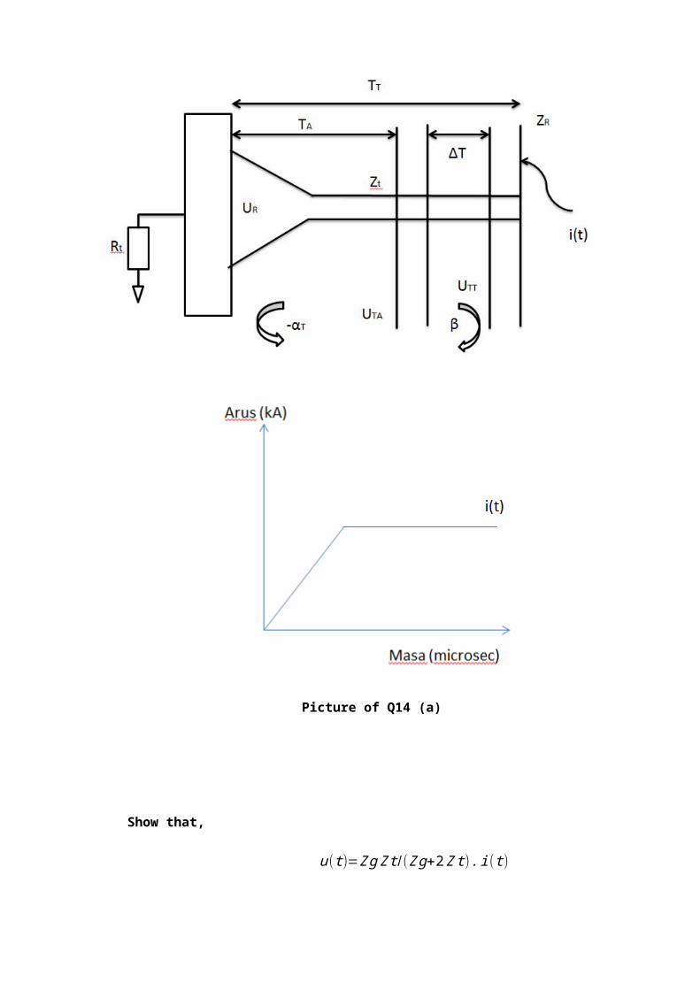
Therefore,
Qc=Cb+Cc
Cb
× Qa=5.79x 10 ˉ ¹²+4.34 x 10ˉ ¹⁴
5.79 x10 ˉ ¹²∙62.52nC ≈ 63nC
Question 2
a) Using the circuit for series and parallel models of an insulating sample, derive the loss
tangent (tan δ ) equation in terms of the capacitance (C) and resistance (R) of the
sample.
Answer
Solid Insulator Model Series Model
Rs = Rp
1+ω2 C2 p R2 p
V
Vr
V
Vc
I
θ
δ
I
Vc
Vr Rs
Cs

Cs = Cp+ 1
ω2 C pR2 p
Tan δ = ¿Vr∨ ¿¿Vc∨¿¿
¿ = IRs
I1ωs
= ωCsRs
Solid Insulator Model Parallel Model
tan δ=¿¿ Ir∨ ¿
¿ Ic∨¿=(
VRp)
(V ωCp)=
1ωCpRp
¿
¿¿
b) What are partial discharges? Describe some of the typical partial discharges.
Answer
Some of the typical partial discharges are:
I
Ir Ic
VRp Cp
Ic
I
Ir
θ
δ
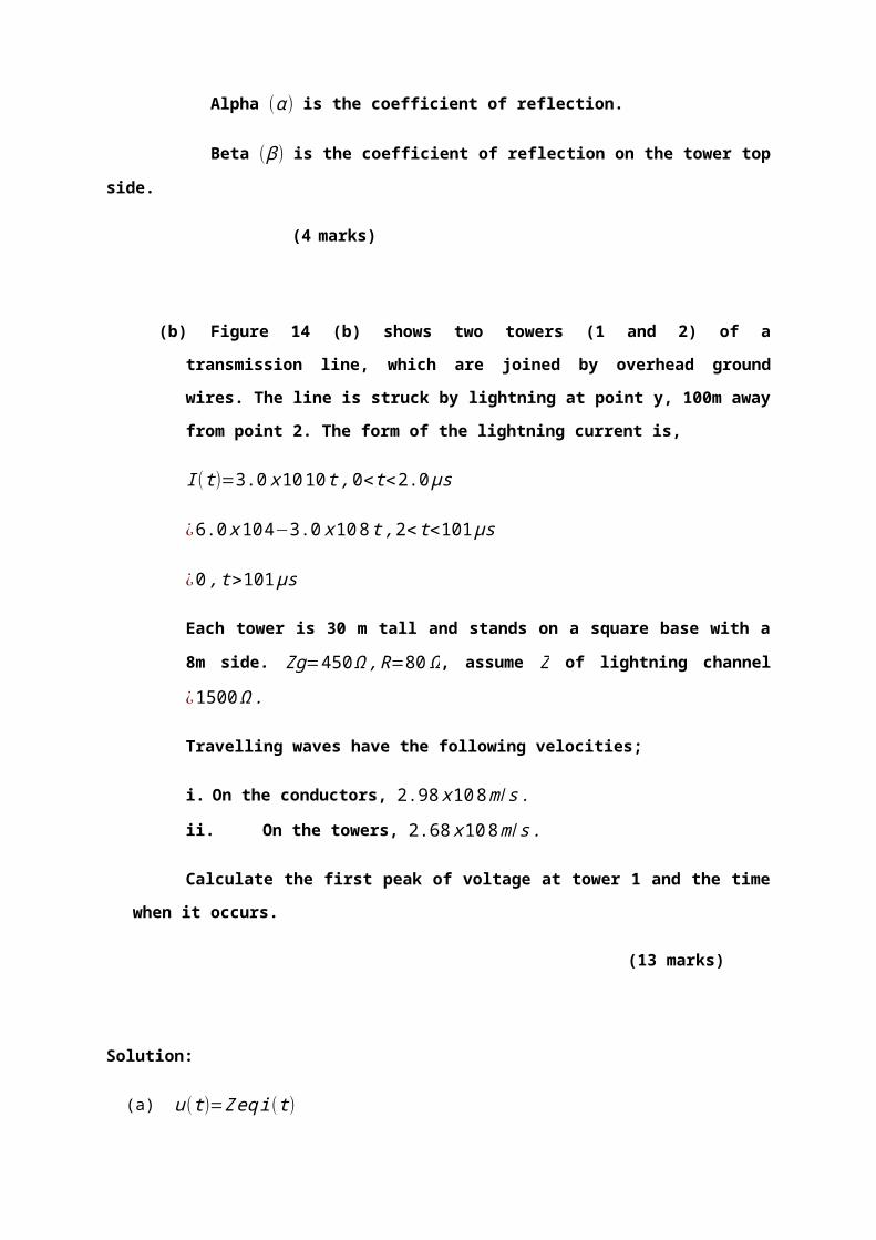
i) Corona or gas discharge. These occur due to non-uniform field in sharp edges of
the conductor subjected to high voltage especially when the insulation provided is
air or gas or liquid. [Fig. (a)]
ii) Surface discharges and discharges in laminated materials on the interfaces of
different dielectric material such as gas/solid interface. [Fig. (a) and (b)]
iii) Cavity discharges: When cavities are formed in solid or liquid insulating materials
the gas in the cavity is over stressed and discharges are formed. [Fig. (d)]
iv) Treeing Channels: High intensity fields are produced in an insulating material at
its sharp edges and this deteriorates the insulating material. The continuous
partial discharges so produced are known as treeing channels. [Fig. (e)]
c) A sample of impregnated paper (Ԑᵣ=3.5) of thickness 2mm is placed between large
parallel-plate electrodes. A cubical air-filled cavity with 2x2 mm length of its edges and
0.05mm deep, with its axis at right angles to the electrodes is located in the centre of
the dielectric. A sinusoidal alternating voltage is applied between the electrodes. The
breakdown voltages of air at different pd level is shown in figure Q5
(i) Determine the discharge inception stress in kV/mm in the dielectric for a pressure
of 550mm Hg.
(ii) Calculate the apparent discharge magnitude.
(iii) If the pressure in the void is doubled, determine the new inception voltage.

Answer
i) Discharge inception voltage, Vᵢ,
V ᵢ=C b+C cC b
.U=(1+C cC b ) .U
where U : breakdown voltage of the void
V i=[1+( ԐoA id1
ԐoԐrAid−di
)] .U=[1+( d−d1Ԑrd 1 )] .U
[1+( 2−0.053.5 x0.05 )] .U=12.14U
U is taken from the graph
At pd = (500)(0.05) = 25; therefore U≈0.46kV
Vi = 12.14 (0.46) = 5.58kV
Inception stress in kV/mm Ei = Vi/d = 5.58/2 = 2.79kV/mm
ii) Apparent discharge qₐ;
qₐ = δVₐ[C ₐ+ C bC cC b+C c
¿ ;∧δ V ₐ=δ Vc ( C bC ₐ C b
)
since Cb << Cc << Ca ; therefore δVa = δVc (CbC a
)
And qₐ = δVc (CbC a
) [ Ca + Cb ] ≈ δVcCb = U.Cb

where Cb =Ԑ oԐrAid−d 1
¿(8 .85x 10 ˉ 12) (3 .5 )(4 x10 ˉ 6)
1 .95 x10 ˉ ³ = 0.064pF
qa = (0.46x10 ˉ ³)(0.064 x10 ˉ 12)=29.44 pF
iii) If p = 2x500 = 100 mmHg
pd = 1000(0.05) = 50
U = 0.74 kV (from the graph)
Vi = 12.14 (U) = (12.14)(0.74) = 8.98kV
Question 3
a) Explain the purpose of insulation diagnostic tests on electrical power equipment. What
are the parameters or properties normally measured when investigating the insulation
performance?
Answer
The purpose of insulation diagnostic testing on the electrical equipment is to estimate
the important of any deterioration that has taken place. The tests are done on
equipment that has been in service for some time or on new equipment. For the in-
service equipment, the results of the test indicate if the equipment can safely be
returned to service or needs a major overhaul.
The parameters or properties that normally measured when investigating the insulation
performance are:
i) Breakdown strength
ii) Conductivity / resistivity
iii) Loss tangent (tan d) / dissipation factor
iv) Permittivity
v) Partial discharge
vi) Non-electrical properties – optical, acoustic, chemical, mechanical etc.
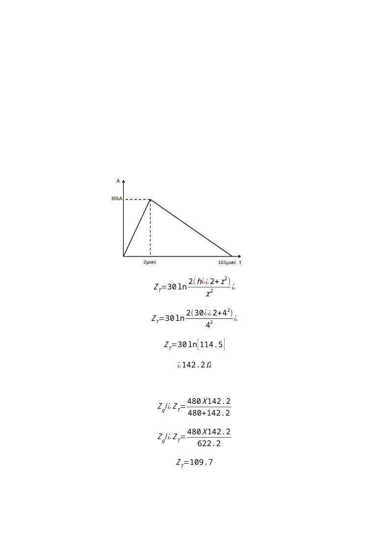
b) The circuit diagram for Schering bridge is shown in Fig. Q5. Both ends of the sample
and the standard capacitor are connected to the high voltage side of the bridge. The
standard capacitor used in the circuit has losses and can be represented as a
capacitance (C2) and resistance (r2) in series.
Show that at balanced condition, the capacitance and the resistance of the sample are:
C=C2
R4
R3
; r=(r 2+R4 C4
C2) R4
R3
Fig. Q5 Schering Bridge
Answer
At balance condition
AC Supply
Standard capacitor with losses
Sample
C4
R4R3
r r2
C2C

Z1 Z 4=Z2 Z3 - equation (i)
Where
Z1=r+ 1jωC
Z2=r+ 1jωC2
Z3=R3
Z4=R4/¿1
jωC4
=R4
1+ jω C4 R4
From equation (i)
Z1=Z2 Z3
Z4
r− jωC=(r2+
1jωC2
)(R3 )
( R4
1+ jω C4 R4)=(r2 R3+
R3
jω C2)(1+ jωC4 R4
R4)
r− jωC=
r2 R3
R4
+R3 C4
C2
− j( R3
ωC2 R4
−ωC4 r2 R3)Equal both side, gives;
r=r2 R3
R4
+R3 C4
C2
; → r=R3
R4(r2+
R4C4
C2)
and
1jωC
=R3
ωC2 R4
−ωC4 r2 R3=R3−ω2C2C4 r2 R3 R4
ωC2 R4
Therefore
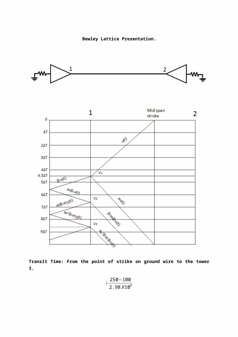
C=C2 R4
R3−ω2C2C4 r2 R3 R4
=R4
R3 ( C2
1−(ωr 2C2) (ωR4 C4 ) )
Normally, ωr 2C2≪1 and ω R4C4 ≪1
Hence C=C2
R4
R3
PROVEN
c) Show that for a solid insulating material of relative permittivity εr, containing a cylindrical
air-filled cavity of depth t, which is small in relation to the thickness T of the dielectric,
the voltage across the sample (Vo) is given by the expression;
V a=Tεr t
× V c
Where Vc is the voltage across the cavity.
From the above equation, explain why the partial discharge can occur in the cavity
even though only the normal service voltage is applied across the insulating material.
Answer

Void in solid dielectric material Equivalent circuit of void in the structure
Void capacitance,
C c=ε0 A1
t
Capacitance series with void,
a
b2
b1
c tVaT
void
Cc
Cb
CaVa

Cb=ε0 εr A1
T−t
Remaining capacitance,
Ca=ε0 εr A1
T
Voltage across cavity,
V c=Cb
Cb+CC
× V a
Therefore
V a=Cb+CC
CC
×V c=( ε0 εr A1
T−t+
ε 0 A1
t )( ε0 A1
t )×V c
Since T >>t;
V a=( εr A1
T+
A1
t )( ε r A1
T )×V c=(1+ T
εr t )× V c
Yields V a=V c+Tεr t
V c proven
In term of electric field strength
V a=Ea T and V c=Ec t
Hence EaT=(1+ Tεr t )E c t
And Tεr t
≫1
EaT=( Tεr t )Ec t ⟹ Ec ≈ εr Ea and ε r>1

Electric stress in the void is greater than the dielectric stress across the sample.
Partial discharge occurs due to the very small gap of the void even at the normal
service voltage.

Question 4
a) The dissipation factor or loss tangent is an indication to determine the performance of
insulating property of insulators. The most common method used to determine the loss
tangent is by using a.c. bridges.
i) Sketch the circuit diagram of a high voltage Schering bridge for the measurement
of loss tangent (tan δ )
ii) Derive the expression for tan δ of the unknown series model of the tested sample
when the high voltage standard capacitor used in the Schering bridge is a loss-
free type.
Answer

C: capacitance of the sample
r: resistance of the sample
C2: standard capacitor
R3, R4 and C4: variable components of Schering Bridge
ii) Given;
AC Supply
Sample
C4R4R3
r
C2
C

Z1=r− 1jωC
Z3=R3
Z4=R4
1+ jω C4 R4
At balance condition
Z1 Z 4=Z2 Z3 - equation (i)
Z1=Z2 Z3
Z4
=( R3
jω C2)( 1+ jωC4 R4
R4)
Z1=r− jωC=
R3C4
C2
− j( R3
ωC2 R4)
By equating the real and imaginary parts of both side;
Therefore: r=C4 R3
C2
; and C=C2 R4
R3
For series model, tan δ=ωCr,
tan δ=ω(C2 R4
R3)(C4 R3
C2)=ωC4 R4
b) A solid insulating material of relative permittivity, ε r comprises a cylindrical air-filled
cavity of depth t. The material has thickness T, where its value is much greater
compared to the depth of the cavity. Show that the voltage across the sample
(material), V ais given by the expression.
V a=Tεr t
× V c
Where V c is the voltage across the cavity.

From the above equation, explain why partial discharge can occur in the cavity even
though only normal service voltage is applied across the insulating material.
Answer
Void in solid dielectric material Equivalent circuit of void in the structure
a
b2
b1
c tVaT
void
Cc
Cb
CaVa

Void capacitance, C c=ε0 A1
t (i)
Capacitance series with void, Cb=ε0 εr A1
T−t (ii)
Remaining capacitance, Ca=ε0 εr A1
T (iii)
Voltage across cavity, V c=Cb
Cb+CC
× V a (iv)
Therefore
V a=Cb+CC
CC
×V c=( ε0 εr A1
T−t+
ε 0 A1
t )( ε0 ε r A1
T−t )×V c
Since T >> t;
V a=( εr A1
T+
A1
t )( ε r A1
T )×V c=(1+ T
εr t )×V c
Yields
V a=V c+Tεr t
V c
proven
In term of electric field strength
V a=Ea T and V c=Ec t
Hence EaT=(1+ Tεr t )E c t

And Tεr t
≫1
EaT=( Tεr t )Ec t ⟹ Ec ≈ εr Ea
Since ε r>1, the electrical stress in the void is greater than the electrical stress across
the sample. Thus, partial discharge occurs due to the very small gap of the void even
at the normal service voltage.
Question 5
a) Partial discharge detection and measurements were limited to the laboratory due to
high levels of electrical noise at the switchyards. With the aid of proper diagrams
describe the main sources of interferences or noise which hampered the partial
discharge detection process and the techniques to suppress the interferences.
Answer
Typical noise source :
i) Power supply
ii) Voltage regulator
iii) High voltage source
iv) Filtering of the HV source
v) Feeder line and electrodes
vi) Coupling capacitor
vii) Loose conductive objects in the vicinity of the last location
viii) Pulse shaped interferences
ix) Electromagnetic waves by radio transmitter (harmonic interferences)
x) Interference currents in ground system of PD measuring instrument
The interferences can be reduced by;
i) Filter grounding
ii) Shielded room
iii) Separate source
iv) Filter AC source (Harmonics)
b) A solid dielectric has a small cavity. Draw an equivalent circuit for such an arrangement
and define all symbols. Derive the expression for electric field strength across the
cavity.
Answer

Void in solid dielectric material Equivalent circuit of void in the structure
In the absence of the void, the electric field within the insulation would everywhere be
Eₐ = Vₐ/d. Neglecting conductance, the insulation, which its void, can be represented
by the three capacitances a, b, and c. The void capacitance is represented by c. If the
void has length d1 and the cross sectional area A1 (perpendicular to d1) then;
a
b2
b1
c tVaT
void
Cc
Cb
CaVa

C = Ԑ₀ A ₁
d₁
The void is connected to the conducting plates through two capacitance b1 and b2 .
Their series combination is represented by the single capacitance b. Clearly,
b = Ԑ₀Ԑᵣ A ₁(d−d₁ )
Where Ԑᵣ is the relative permittivity of the insulating material. The remaining capacitor
a has the value,
a=Ԑ₀ԐᵣA(d )
Where A is the cross sectional area of the insulation, minus the (usually small) cross
sectional area of the void.
The voltage across the void is;
V c=C b
C b+Cc.Vₐ
And substituting for the capacitances gives,
V c=VₐԐᵣd ₁
Ԑᵣd ₁+(d−d₁ )
In the term of electric field strength we have,
Vₐ =Eₐ.T and Vc = EC.t
Where Ec is the dielectric field strength in the void. Substituting in equation gives,
EC=EₐԐᵣd ₁
Ԑᵣd ₁+(d−d ₁ )

Usually the void will be small, so that d₁<< d and Ԑᵣd₁<< d. Consequently,
EC ≈ ԐᵣEₐ
This shows that the field strength I n the void is greater than the field strength in the
insulating material. Because the gas in the void is likely to have a lower breakdown
strength that the insulating material, partial discharge are very probable.
c) While doing studies on partial discharges in cavities of cylindrical disc of 1.0cm
diameter and 1cm thickness, a cylindrical cavity of 1mm diameter and 1mm thickness
is made its center. The discharge voltage measured across the specimen is 0.2 V with
sensitivity of 1pC/volt. Determine the magnitude of charge transferred from the cavity
by taking Ԑᵣ of the disc to be equal to 2.5.
Answer
1pC = 1volt, since the discharge magnitude measured = 0.2pC.
Capacitance of the cavity, Cₐ = Ԑ0 xarea
Thickness = Ԑ₀( π
4 ) (1 x10¯ ³ )²(1x 10¯ ³ )
= πԐ0 x10¯ ³
4F
Capacitance, Cb = Ԑ0 xarea
Thickness =
Ԑ0 X 2 X 5 X ( π4 )X (1x 10¯ ³ ) ²
9 x10¯ ³
= (Ԑ ₀ Xπ4 )X ( 2.5
9 )X 10¯ 3
Thus qc = C ₐ+C b
C b X 0.2 = 0.92pC
Question 6

a) Breakdown in solid or liquid dielectrics arises from the action of electrical discharges in
internal gaseous cavities. Draw an equivalent circuit for such an arrangement and
device the expression for energy dissipated in the cavity in one discharge.
Answer
Void in solid dielectric material Equivalent circuit of void in the structure
a
b2
b1
c tVaT
void
Cc
Cb
CaVa

Cc= εₒA ₁d ₁
Cb= εₒ εᵣ A ₁(d−d ₁)
Ca= εₒ εᵣ Ad
Energy dissipated in the cavity in one discharge;
= ½ [Cc+(CaCb )(Ca+Cb)
]Vc ²
= ½ [Cc+(CaCb )(Ca+Cb)
][ Cb(Cb+Cc)
] ² Va ²
= ½Cb ²Cc
Va ²
b) A Schering Bridge as shown in figure 5 is used to measure the dielectric loss and
capacitance of the insulation of an electrical power equipment. Prove that the
capacitance, C and tangent loss are given by;
C=C ₂R ₄R ₃
and tan δ=ωC ₄R ₄
Answer

The circuit of the Schering Bridge is shown in Figure. The unknown is represented by C
and r in series. ThusZ1=r+ 1j ωC
, and the unknown has loss tangent, tan δ=ωCr .
C₂ is standard capacitor. Often an air capacitor is used in this position, being loss free.
To balance the bridge it is necessary to have two variable components. Normally one
of these is C₄ and the other one is either R₃ or R₄. Balance occurs when,
Z₁ Z₄ = Z₂ Z₃
AC Supply
Sample
C4R4R3
r
C2
C
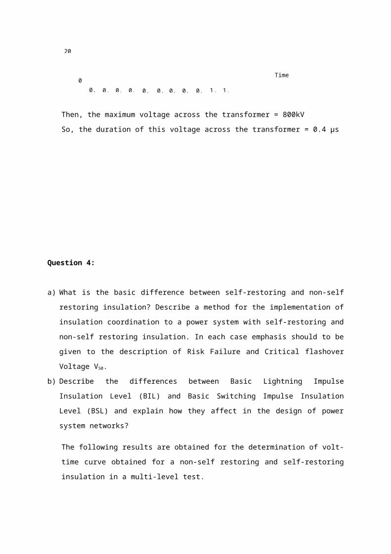
That is when,
(r –j
ωC )R 4
1j ωc 2
R 4+1
j ωc 4
=R ₃
j ωC ₂
Re-arranging and separating into real and imaginary parts gives the balance
condition,
r = R ₃C ₄C ₂
and C = C ₂R ₄R ₃
Substituting in tan δ=ωCr
Gives tan δ=ωC ₄R ₄ proved
c) A solid dielectric specimen of 5cm diameter and 10mm thickness has dielectric
constant of 3. It has an embedded air filled void of 2.5mm diameter and 1mm
thickness. It is subjected to a voltage of 100kVrms. Find the voltage at which an
internal discharge in the void can occur. The breakdown strength of air is 3kV/mm. Also
determine the charge the value each time there is discharge inside the void and what
will be the value of charge as measured on the detector?
Answer
The inception voltage of the stressed void Vi is given by;
Vi=Ecb t 1+ 1ε r ( dt −1)
Where
Ecb - breakdown stress of the void = 3 kV/mm
d - thickness of the specimen = 10mm
t - thickness of the void = 1mm
εr - dielectric constant of the specimen = 3

when t = 1mm
Vi=3∗1 1+13 ( 10
1−1)=12kV peak
when t = 0.1mm
Vi=3∗0.11+ 13 ( 10
0.1−1)=10.2kV peak
This shows that the smaller is the void then the lower becomes the discharge inception
voltage
Capacitance of void
Cc=εo εr A/ t
When t = 1mm, area of void = π (2.5 x10 ˉ ³) ² /4=491 x10 ˉ ⁶m ²
Cc=(8.854 x 10ˉ ¹²)(1)(491 x10 ˉ ⁶)
1x 10 ˉ ³
¿4.34 x10 ˉ 14
Capacitance of slab
Ca=εoεr A /d
Ca=(8.854 x 10 ˉ 12) (3 ) (0.025 )2 (3.14 )
0.01
¿5.21 x10 ˉ 12 F
Cb=ε o ε rA
[d−t ]

¿5.79 x10 ˉ 12 F
The measured change
Qa=Vi .Ca
Qa=(12x 10 ³)(5.21x 10 ˉ ¹²)
¿62.52nC
Qa= CbCb+Cc
× Qc
Therefore,
Qc=Cb+CcCb
×Qa
¿( 5.79 x10 ˉ ¹²+4.34 x10 ˉ ¹⁴5.79x 10 ˉ ¹² )×62.52nC
Qc=63nC
Therefore measured change is around 1.0% less than the actual charge

Question 7
a) A solid dielectric has a small cavity. Draw an equivalent circuit for such an arrangement
and define all symbols. Under what conditions will this system have a partial
discharge?
Answer
Fig 5.1 A cavity in a dielectric and its “abc” equivalent circuit.
Cc = Capacitance of the cavity
Cb = Capacitance of the dielectric which in series with Cc
Ca = Capacitance of the rest at the dielectric
Va = Voltage apply to the dielectric
Vc = Voltage across the cavity
b) From a survey conducted on faulty 22kV polyethylene cables that have been in service
from at least one year to tens of years were found to experience fault due to several
factors. The factor were due to unknown cause, treeing, insulation failure and others.
Cables which were just within of one year of installation faulty due to unknown reasons
while the one being installed within three years were found to have traces of treeing
initiated from the cable sheath to the cable conductor. Explain briefly the initialization of
treeing in cable insulation and how it can cause insulation failure.
Answer
Electrical treeing initiate and propagate in a dry dielectric due to high and divergent
electric stress at metallic or semiconducting contaminant and/or void due to partial
discharge such trees consist of hollow channel, resulting from decomposition of

dielectric materials by the PDs. The tree shows up clearly in translucent solid dielectric
when examined with an optical microscope and transmitted light. Electrical tree
channels are permanently visible and there is a great variety of the visual appearance
of stems and branches of such trees as well as the circumstances in which initiation
and growth of such trees occur
a) Branch type b) Bush Type
c) A solid dielectric specimen of 5cm diameter and 10mm thickness has dielectric
constant of 3. It has embedded air filled void of 2.5mm diameter and 1mm thickness.
It is subjected to a voltage of 100kVrms. Find the voltage at which an internal
discharge in the void can occur. The breakdown strength of air is 3kV/mm. Also
determine the charge value each time there is discharge inside the void and what will
be the value of charge as measured on the detector? If the cavity thickness is
reduced to 10µm, what will be its effect on the discharge inception voltage?
Answer
The inception voltage of the stressed void Vi is given by as:
Vi=Ecb t 1+ 1εr ( d
tc−1)
where,
Ecb = breakdown stress of the void = 3kV/n

t = thickness at the specimen = 10mm
tc = thickness of the void
= 1mm or 0.1 mm for the last case
εr = dielectric constant of the specimen = 3
When t = 1mm then
Vi=3 x1 1+ 13 (10
1−1)
¿12kV peak
When t = 0.1mm then
Vi=3 x0.1 1+ 13 ( 10
0.1−1)
¿10.2kV peak
This shows that smaller is the void them lower becomes the discharge inception
voltage.
Capacitance of void
Cc=εo εrAt
When tc = 1mm, area of void
¿ π (2.5 x10 ˉ ³) ²/ 4=491 x10 ˉ ⁶m ²
Cc=(8.854 x 10ˉ ¹²)(1)(491 x10 ˉ 6)
1 x10 ˉ ³

¿4.34 x10 ˉ 14
Capacitance of slab
Ca=εoεr A / t
Ca=(8.854 x10 ˉ ¹²)(3)(0.025)² (3.14)
0.01
¿5.21 x10 ˉ ¹² F
Cb=εo εr A /[ t−tc ]
¿5.79 x10 ˉ ¹² F
The measured change
Qa=Vi .Ca
Qa=(120x 10 ²)(5.21x 10 ˉ ¹²)
¿62.52nC
Qa= CbCb+Cc
× Qc
Therefore,
Qc=Cb+CcCb
xQa
¿ 5.79x 10ˉ 12+4.34 x10 ˉ 14
5.79 x10 ˉ 12 x 62.52nC
Qc=63.0nC

Therefore measured change is around 1.0% less than the actual charge.
Question 8
a) A solid dielectric has a small cavity. Draw an equivalent circuit for such an arrangement
and define all symbols. Under what conditions will this system have a partial
discharge?
Answer
Fig 5.1 a cavity in a dielectric and its “abc” equivalent circuit.
Cc = Capacitance of the cavity
Cb = Capacitance of the dielectric which in series with Cc
Ca = Capacitance of the rest at the dielectric
Va = Voltage apply to the dielectric
Vc = Voltage across the cavity
b) From a survey conducted on faulty 22kV polyethylene cables that have been in service
from at least one year to tens of years were found to experience fault due to several
factors. The factor were due to unknown cause, treeing, insulation failure and others.
Cables which were just within of one year of installation faulty due to unknown reasons
while the one being installed within three years were found to have traces of treeing
initiated from the cable sheath to the cable conductor. Explain briefly the initialization of
treeing in cable insulation and how it can cause insulation failure.
Answer
Electrical treeing initiate and propagate in a dry dielectric due to high and divergent
electric stress at metallic or semiconducting contaminant and/or void due to partial
discharge such trees consist of hollow channel, resulting from decomposition of

dielectric materials by the PDs. The tree shows up clearly in translucent solid dielectric
when examined with an optical microscope and transmitted light. Electrical tree
channels are permanently visible and there is a great variety of the visual appearance
of stems and branches of such trees as well as the circumstances in which initiation
and growth of such trees occur.
a) Branch type b) Bush Type
c) A solid dielectric specimen of 5cm diameter and 10mm thickness has dielectric
constant of 3. It has embedded air filled void of 2.5mm diameter and 1mm thickness. It
is subjected to a voltage of 100kVrms. Find the voltage at which an internal discharge
in the void can occur. The breakdown strength of air is 3kV/mm. Also determine the
charge value each time there is discharge inside the void and what will be the value of
charge as measured on the detector? If the cavity thickness is reduced to 10µm, what
will be its effect on the discharge inception voltage?
Answer
The inception voltage of the stressed void Vi is given by as:
Vi=Ecb t 1+ 1εr ( d
tc−1)
where,

Ecb = breakdown stress of the void = 3kV/n
t = thickness at the specimen = 10mm
tc = thickness of the void
= 1mm or 0.1 mm for the last case
εr = dielectric constant of the specimen = 3
i) When t = 1mm then
Vi=3 x1 1+ 13 (10
1−1)
¿12kV peak
ii) When t = 0.1mm then
Vi=3 x0.1 1+ 13 ( 10
0.1−1)
¿10.2kV peak
This shows that smaller is the void them lower becomes the discharge inception
voltage.
iii) Capacitance of void
Cc=εo εrAt
When tc = 1mm, area of void
¿ π (2.5 x10 ˉ ³) ²/ 4=491 x10 ˉ ⁶m ²
Cc=(8.854 x 10ˉ ¹²)(1)(491 x10 ˉ 6)
1 x10 ˉ ³
¿4.34 x10 ˉ 14

Capacitance of slab
Ca=εoεr A / t
Ca=(8.854 x10 ˉ ¹²)(3)(0.025)² (3.14)
0.01
¿5.21 x10 ˉ ¹² F
Cb=εo εr A /[ t−tc ]
¿5.79 x10 ˉ ¹² F
The measured change
Qa=Vi .Ca
Qa=(120x 10 ²)(5.21x 10 ˉ ¹²)
¿62.52nC
Qa= CbCb+Cc
× Qc
Therefore,
Qc=Cb+CcCb
xQa
¿ 5.79x 10ˉ 12+4.34 x10 ˉ 14
5.79 x10 ˉ 12 x 62.52nC
Qc=63.0nC
Therefore measured change is around 1.0% less than the actual charge in the
void.

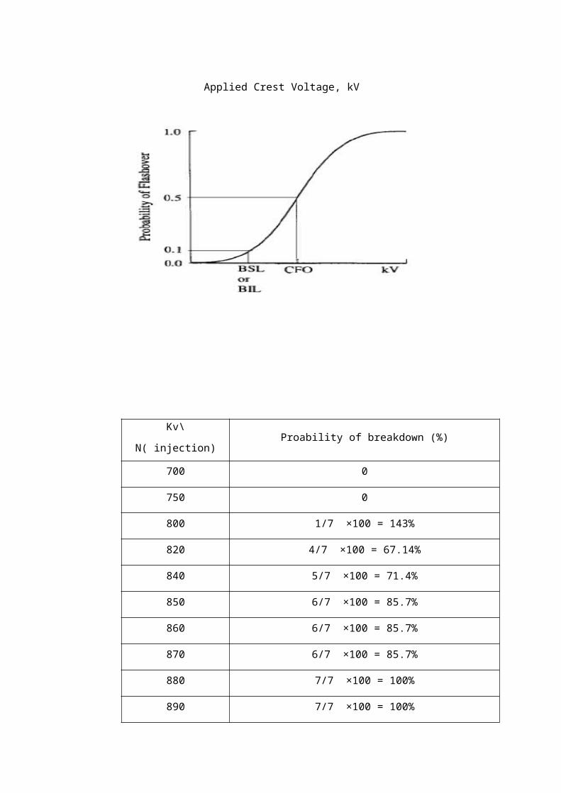
Question 9
A solid can be modeled either as parallel or series model as shown in below. Derive the
equation for tangent loss, tan δ for both models.
Solid Insulator Model Series Model
Cs
RsVr
Vc
I
δ
θ
I
Vc
V
Vr
V

Solid Insulator Model Parallel Model
Answer
δ
θ
Ir
I
Ic
CpRpV
IcIr
I
V
Vr
V
Vc
I
θ
δ
I
Vc
Vr Rs
Cs

Solid Insulator Model Series Model
Rs = Rp
1+ω2 C2 p R2 p
Cs = Cp+ 1
ω2 C pR2 p
Tan δ = ¿Vr∨ ¿¿Vc∨¿¿
¿ = IRs
I1ωs
= ωCsRs
Solid Insulator Model Parallel Model
tan δ=¿¿ Ir∨ ¿
¿ Ic∨¿=(
VRp)
(V ωCp)=
1ωCpRp
¿
¿¿
I
Ir Ic
VRp Cp
Ic
I
Ir
θ
δ

Question 10
a) How does the “internal discharge” phenomena lead to breakdown in solid dielectrics?
Answer
Cause gradual deterioration of the insulating materials, sometimes over a period of several
years, leading perhaps to eventual failure.
b) A solid dielectric has a small cavity. Draw an equivalent circuit for such an arrangement
and define all symbols. Under What condition will this system have a partial discharge?
Answer
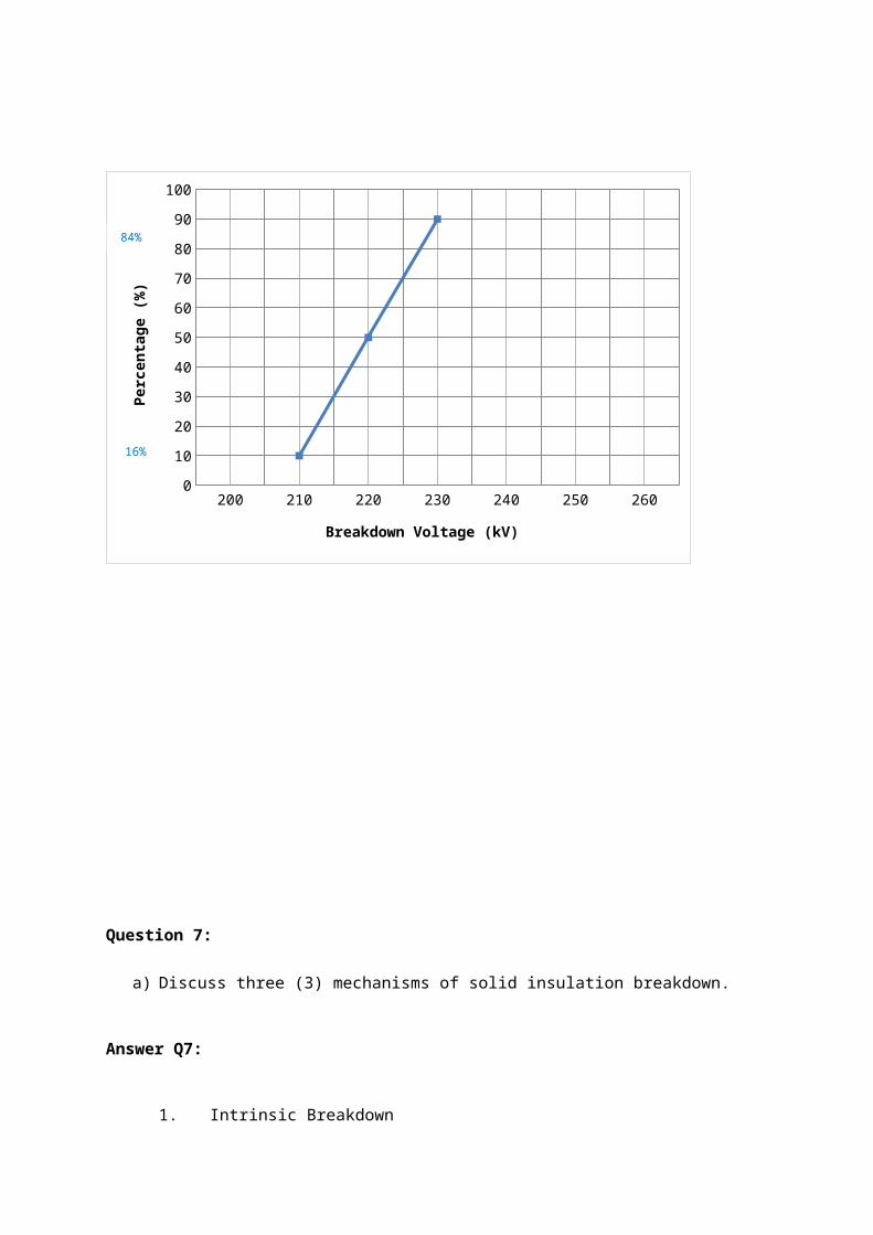
Void in solid dielectric material Equivalent circuit of void in the structure
Usually the void will be small, so that d₁<< d and Ԑᵣd₁<< d. Consequently,
EC ≈ ԐᵣEₐ
a
b2
b1
c tVaT
void
Cc
Cb
CaVa

This shows that the field strength In the void is greater than the field strength in the
insulating material. Because the gas in the void is likely to have a lower breakdown
strength that the insulating material, partial discharge are very probable.
c) A solid dielectric specimen of 5cm diameter and 10mm thickness has dielectric
constant of 3. It has an embedded air filled void of 2.5mm diameter and 1mm
thickness. It is subjected to a voltage of 100kVrms. Find the voltage at which an
internal discharge in the void can occur. The breakdown strength of air is 3kV/mm. Also
determine the charge the value each time there is discharge inside the void and what
will be the value of charge as measured on the detector? If the cavity thickness is
reduce to 100 μm, What will be its effect on the discharge inception voltage?
Answer
The inception voltage of the stressed void Vi is given by;
Vi = Ecb t 1+1/εr (d/t-1)
Where
Ecb - breakdown stress of the void = 3 kV/mm
d - thickness of the specimen = 10mm
t - thickness of the void = 1mm
εr - dielectric constant of the specimen = 3
when t = 1mm
Vi = 3 * 1 1 + 1/3 (10/1 - 1) = 12 kV peak
when t = 0.1mm
Vi = 3 * 0.1 1 + 1/3 (10/0.1 - 1) = 10.2 kV peak
This shows that the smaller is the void then the lower becomes the discharge inception
voltage
Capacitance of void
Cc = εo εr A/t
When t = 1mm, area of void = π (2.5 x 10ˉ³)² / 4 = 491 x 10ˉ⁶ m²
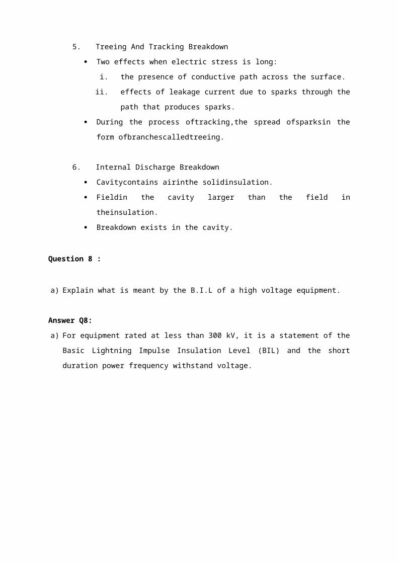
Cc = (8.854 x 10ˉ¹²) (1) (491 x 10ˉ⁶)
1 x 10ˉ³
= 4.34 x 10ˉ¹⁴
Capacitance of slab
Ca = εo εr A/d
Ca = (8.854 x 10ˉ¹²) (3) (0.025)² (3.14)
0.01
= 5.21 x 10ˉ¹²F
Cb = εo εr A/[d-t]
= 5.79 x 10ˉ¹² F
The measured change
Qa = Vi . Ca
Qa = (12 x 10³) (5.21 x 10ˉ¹²)
= 62.52nC
Qa = ___Cb____. Qc
Cb + Cc
Therefore,
Qc = _Cb_+ Cc_. Qa
Cb
5.79 x 10ˉ¹² + 4.34 x 10ˉ¹⁴ . 62.52nC
5.79 x 10ˉ¹²
Qc = 63nC

Therefore measured change is around 1.0% less than the actual charge.

Question 11
a) A Schering Bridge as shown in Figure Q7b is used to measure the dielectric loss and
capacitance of the insulation of an electrical power equipment. Prove that the
capacitance, C and tangent loss are given by;
C=C2 R4
R3
and tan δ=ωC4 R4
ANSWER
A Schering Bridge as shown in Figure Q7b is used to measure the dielectric loss and
capacitance of the insulation of an electrical power equipment. Prove that the
capacitance, C and tangent loss are given by;
C=C2 R4
R3
and tan δ=ωC4 R4

Z1 Z 4=Z2 Z3
That is when,
(r− j /ωC )R4
1jωC2
R4+1
jωC4
=R3
jω C2
Re-arranging and separating into real and imaginary parts gives the balance condition,
AC Supply
Sample
C4R4R3
r
C2
C

r=R3
C4
C2
and C=C2
R4
R3
Substituting in tan ω=ωCr gives,
tan δ=ωC4 R4 proved
Question 12
a) In a strongly inhomogeneous field, external partial discharges occur at electrodes of
small radius of curvature when a definite voltage is exceeded. These are referred to as
corona discharges and depending upon the voltage amplitude, they result in a large
number of charge pulses of very short duration. With the aid of diagram where
appropriate;
i) Define the terms corona.
ii) Types of corona and how it occurs.
iii) The problems which are created by corona discharges on high voltage
transmission lines.
Answer
i) The term corona is used to describe the discharge phenomena which occur at
highly stressed electrodes prior to the complete breakdown of the gap between
the electrodes. It is a partial discharge in air around a sharp point or thin wire in a
strong, non-uniform field. It is characterized by a visible glow, an audible noise,
radio interference, chemical effects such as production of ozone and loss of
electrical power. It occurs whenever the local voltage gradient exceeds the
ionization value of the air and depends on the air density, humidity and in outdoor
situations whether it is fair weather or raining and also on the roughness of the
conductor surface.
ii) Corona can be classified into:
DC Corona.
Positive corona (anode)

When the highly stressed electrode is the anode, the following corona
modes are observed as the voltage is increased.
- Onset streamers
Also known as ‘burst’ pulses, these are intermittent, filamentary discharges
which propagates only a short distance from the highly stressed electrodes.
- Hermstein glow
As the voltage is increased, the intermittent streamer discharges give way
to a steady glow discharges. This transition occurs when a large enough
negative ion space is generated near the anode to give a quasi-uniform
field in that region.
- Breakdown streamer
Eventually, the shielding effect of the glow discharge is not able to prevent
the formation of large streamers which propagates well into the gap.

Onset streamers Hermstein glow Breakdown streamer
Negative corona (cathode)
When the highly stressed electrode is negative, three modes are again
observed.
- Trichel pulses
These differ from the burst pulses in that their magnitude and repetition
frequency are both very regular.
- Cathode glow
As the voltage is raised a critical Trichel pulse repetition frequency is
reached and the repetitive discharge is replaced by a steady cathode glow.
- Negative streamer
These discharges are usually known as negative feathers to avoid
confusion with positive streamer discharges. They develop out of the glow
mode and a long rise time compared with other pulsating coronas.

Trichel pulses Cathode glow Negative streamer
AC Corona
With an alternating voltage applied, the same basic corona types will
appear although their characteristics may be altered to an extent which
depends on the gap length

- Small gaps (d ≤ 100cm)
Here, the ions generated in any of the corona modes above are able to
cross the gap during one half cycle to the next and the corona modes will
therefore be similar to those for direct voltages, although all three modes
may be observed in one half cycle.
- Large gaps (d > 1m)
For those gaps, space charge can persist from one half cycles to the next
and can have an effect on the corona modes observed. The usual effect is
to enhance the positive glow phase. Further, the negative streamer is never
observed in ac stressed gaps, since its onset potential is higher than the
positive polarity breakdown voltage. Breakdown always occurs on the
positive half cycle.
ii) Transmission line corona
The above description of the types of corona discharge referred particularly to the
point plane gap where there is a single site for discharges to occur. On a
transmission line, corona may occur anywhere on the line and the average
corona currents will be much higher.
iii) The problems which are created by corona discharges on high voltage
transmission lines are;
Power losses
The power losses depend upon the maximum gradient for which the line is
designed. For the single conductor, this occurs at the conductor surface.
For the given cross section of conductor required for current carrying
capacity, the maximum stress may be reduced by using bundled
conductors in which 2,4 or 6 wire assembly is used.
Radio interference
Radio interference is caused only by the pulse corona modes and only
Trichel pulses and positive streamers are of interest. The positive
streamers usually have shorter rise time than the Trichel pulses and greater
amplitude, so that the rate of change of current is greater and their RI effect

is therefore greater. These corona discharges cause radiation of
electromagnetic waves.
Audible noise
Recent studies of EHV and UHV lines indicate that audible noise may be a
problem where such lines pass near inhabit areas. Difficulties arise in
monitoring such noise levels as the ‘apparent noise’ is a non-linear function
of frequency. Measuring instruments have thus been developed which have
a similar response to the human ear and levels have been se based limits
at which most people find the noise objectionable.
b) Partial discharge detection and measurements were limited to the laboratory due to
high levels of electrical noise at the switchyards. With the aid of proper diagram;
i) Describe in details the main sources of interference or noise which hampered the
partial discharge detection and measurement process.
ii) The technique which are widely used to suppress the noise in order to measure
the partial discharges.
Answer
The source of the noise is listed as below:
i) The power system's noise through the apparatus outlets, which may excited by
the internal discharge of other equipments in power system, such as discharge of
the bus bar, switching of the breaker and so on.
ii) The high frequency noise such as coupling by capacitor and inductor form the
generator's rotator DC excitation. These noise may originated by the thyristor of
excitation system.
iii) The external noise from the environment outside, such as broadcasting
interference of AM radio and high frequency signals from mobile phone.
iv) The noise in diagnosis system itself, such as noise of circuit or switch power
supply

v) The technique which are widely used to suppress the noise in order to measure
the partial discharges. Band pass Filter, FFT Filter, Wavelet Filter, Neural
Network Filter to eliminate the noise.
Question 13
a) (i) Define the breakdown of electrical insulation.
(ii) List all mechanism of breakdown in solid and liquid insulation.
Answer
i) Electrical breakdown in insulation the maximum voltage that can be covered by
an insulating material
ii) List breakdown mechanisms in insulating
Electrodynamic
Heat
Chemical and electrochemical
Internal discharge
Tracking
b) Explain the Townsend mechanism of breakdown in the gas medium and prove that
creation of breakdown is given by (all symbols have their usual meanings):
ɤeᵉᵈ=1
Answer
Townsend breakdown mechanism used to reduce the breakdown in the gas business.
This mechanism did in low pressure conditions and the small distance between the
electrodes, the voltage supplied to the electrodes until breakdown occurs. Breakdown
process begins with the creation of the first and subsequent calculation of the
coefficient of voltage increase will occur and thus the distribution of secondary
breakdown occurs. Currents equation taking into account the secondary generator.
I= Io x eᵉᵈ1−γ (eᵉᵈ−1)

Take the breakdown criteria by taking the equation below:-
1−γ (eᵉᵈ−1)=0
γ (eᵉᵈ−1)=1
Because of; γ eᵉᵈ ≫1
Their for; γ eᵉᵈ=1
c) Breakdown voltage measurement of a uniform field pressurized gas is shown in table
below.
Distance (mm) 20.3 28.8
Pressure (mbar) 500 700
Temperature (°C) 20 25
Breakdown voltage (kV) 31.6 53
Answer
At a distance; d1 = 20.3 mm, P1 = 500mb, t1 = 20 °C, V1 = 31.6 kV
P= P11013 ( 273+20
273+t )
P= 5001013 ( 273+20
273+t )
P=0.4936
31.6=A x0.4936 x 20.3+B √0.4936 x 20.3
31.06=10.02 A+B (3.165) ………. E1

At a distance; d2 = 28.8 mm, P2 = 700mb, t2 = 29 °C, V2 = 53 kV
P= P21013 ( 273+20
273+25 )
P= 5001013 ( 293
298 )
P=0.6794
53=A x 0.6794 x 28.8+B√0.6794 x 28.8
53=19.57 A+B (4.424 ) ……. E2
When E1 x 19.57
618.412=196.09 A+61.94B
When E2 x 10.02
531.06=196.09 A+44.33 B
E1 to E2
87.352=17.61B
B=4.96
From E1
A=( 31.6−15.710.02 )
A=1.587

At a distance; d3 = 15.5 mm, P3 = 250mb, t3 = 25 °C, V3 =? kV
P= P21013 ( 273+20
273+25 )
P= 5001013 ( 293
298 )P=0.2427
V 3=1.587 x 0.2427 x15+4.96√0.2427 x1
V 3=15.24 kV
d) (i) Explain what is meant by partial discharge in high voltage engineering.
(ii) What are the effects to high voltage apparatus if the partial discharge level is
greater than the maximum allowed.
Answer
i) Partial discharge is an electrical discharge that only partially bridge the insulating
medium.
ii) The cable will damage because of the high partial discharge level is greater from
the limit of insulation limit.
Question 14
a) Write short discussions on the followings:
i) Paschens Law and its significance in gas breakdown phenomena;
ii) Thermal breakdown of solid insulators
Answer
a) i) Paschen’s Law is found to be valid over a wide range of partial discharge values.
At higher partial discharge values, the breakdown voltage in some gases is found

to e slightly higher than the values at smaller gaps for the same values of partial
discharge.
ii) Thermal breakdown is based on the experimental observation of extremely large
current just before breakdown. These high current pulses are believed to
originate from the tips of the microscopic projections on the cathode surface with
densities of the order of 1 A/cmᵌ.
CHAPTER 6
HIGH VOLTAGE GENERATION
(QUESTION AND ANSWER)

QUESTION 1
a) Describe and give an example, the significance of routine tests, type tests and
maintenance tests on high voltage equipment.
ANSWER
Routine tests are done on equipment for the purpose of eliminating equipment with
manufacturing defects by non-destructive tests. These are generally easily verifiable. Made
by manufacturer on every finished piece of product to fulfills the specifications. Example:
Resistance measurement on power transformer or partial discharge measurement in high
voltage cables.
Type tests are done on equipment to establish that the particular design is suitable for a
particular purpose. They are normally done once on new designs and when specifically
requested by consumers purchasing in bulk quantities. Performed on each type of equipment
before their supply on a general commercial scale – demonstrate performance
characteristics.
Example: One minute rain test on porcelain insulator where the insulator is sprayed
throughout the tests with artificial rain or temperature rise test and lightning impulse test on
power transformers.

Maintenance tests are usually carried out after maintenance/repair of the equipment and
conducted according the schedule provided. Purpose of the test is to ensure the equipment
lifetime is achieved.
Example: Partial discharge measurement on cables and oil breakdown test on transformer.
b) Describe briefly, with the aid of suitable diagrams the cascade arrangement of
transformers to obtain high alternating voltage for testing purposes.
ANSWER
Figure 1 shows a typical cascade arrangement of transformers used to obtain up to 300 kV
from three units each rated at 100 kV insulation. The low voltage winding is connected to the
primary of the first transformer, and this is connected to the transformer tank which is
earthed. One end of the high voltage winding is also earthed through the tank. The high
voltage end and a tapping near this end is taken out at the top of the transformer through a
bushing, and forms the primary of the second transformer. One end of this winding is
connected to the tank of the second transformer to maintain the tank at high voltage. The
secondary of this transformer too has one end connected to the tank at high voltage.
Figure 1
The secondary of this transformer too has one end connected to the tank and at the other
end the next cascaded transformer is fed. This cascade arrangement can be continued
further if a still higher voltage is required. In the cascade arrangement shown, each
transformer needs only to be insulated for 100 kV, and hence the transformer can be
relatively small. If a 300kV. Transformer had to be used instead, the size would be massive.
High voltage transformers for testing purposes are designed purposely to have a poor
regulation. This is to ensure that when the secondary of the transformer is short circuited (as

will commonly happen in flash-over tests of insulation), the current would not increase to too
high a value and to reduce the cost. In practice, an additional series resistance (commonly a
water resistance) is also used in such cases to limit the current and prevent possible damage
to the transformer.
c) A six-stage impulse generator designed to generate the standard waveform
(1.2/50µs) has a per stage capacitance of 0.06µF to be used to test transformers with
an equivalent winding to earth capacitance of 1nF. A peak output voltage of 550kV is
required for testing the transformer.
ANSWER
i) With the aid of appropriate calculations select the values of resistive elements in the circuit to produce the required waveform. State any assumptions made.
c1=6 of 0.06 μF=0.06/6=0.01μF (Capacitor effectively∈series )c2=1nFStandard waveform1.2 /50 μs ¿ time ,t 1=3 R1¿
1.2×10−6=3R1
(0.01×10−6× 110−9)(0.01× 10⁻⁶+1×10⁻⁹)
¿3 R1
(1×10⁻¹⁷)(1.1×10⁻⁸)
¿2.73×10⁻⁹ R1
∴R1=440Ω.
Tail time , t 2=0.7 (R1+R2) (C1+C2 )
50×10−6=0.7 (440+R2 ) (0.01× 10⁻⁶ )
50×10−6=0.7¿
7.7×10−9=(440+R2 )
∴R2=6494kΩ
¿1.01kΩ per stage

ii) Draw the basic circuit diagram of the multi-stage impulse generator indicating
all relevant values on it. Indicate also on the diagram the wavefront and
wavetail control resistors and the charging resistors.
ANSWER

QUESTION 2
a) Describe the types of test conducted on high voltage equipment .
ANSWER
i) Routine Tests
Routine tests are made by the manufacturer on every finished piece of product to
make such that it fulfills the specifications. Acceptance and commissioning tests
are made by the purchaser and self-explanatory. Routine testing such as a
power-frequency overvoltage tests is performed on every unit at the
manufacturer’s factory and possibly after receipt of the unit by the purchaser.
ii) Type tests
Type tests are performed on each type of equipment before their supply on a
general commercial scale so as to demonstrate performance characteristics
Wavefront control resistor
Wavetail control resistors
Wavetail control resistors

meeting the intended application. These tests are of such a nature that they need
not be repeated unless changes are made in the design of the product. Type
testing, such as an impulse voltage test, is done to prove the specifications of a
new design and is probably restricted to one or two units of each design.
iii) Maintenance Tests
Maintenance tests are usually carried out after maintenance or repair of the
equipment. Normally this tests is conducted according to the schedule provided.
The purpose of the maintenance test is to ensure the lifetime of the equipment is
achieved.
iv) Special TestSpecial tests are tests other than the above.
b) With the aid of suitable diagrams discuss the generations of high voltage direct
current (HVDC) using the full wave rectifier circuit.
ANSWER
Full Wave Rectifier for HVDC generation
Full wave rectifiers produce dc voltage less than ac maximum voltage. Ripple or voltage
fluctuation will be present and this has to be kept within a reasonable limit by means of filters.
During the +ve half-cycle, rectifier A conducts and charged up capacitor, C (smoothing
capacitor). During the –ve half-cycle, rectifier B conducts and charged up C. The source
transformer requires a centre tapped secondary with rating of 2V. The output waveform is
shown in the figure below:

c) Lightning impulse voltage is simulated in the laboratory using an impulse
generator and is used to conduct lightning impulse tests on high voltage
equipment based on standard test procedures. An impulse generator
(unmodified Marx) has five (5) stages. The following circuit elements are
available: 100kV – rated 0.2µF capacitors, a 300Ω front resistor, and a 2500Ω tail
resistor. The load capacitor is given as 100pF.
ANSWER
i) Determine the output impulse waveshape of generator and give comments on the
waveshape as compared to the standard test procedure.
Charging capacitor ,C1=0.2/5=0.04 μF
Load capacitor ,C2=0.001 μF
Front timet 1=3.0 R 1C1C2
C1+C2

¿3 (300¿ 0.04 ×10−6 × 0.001×10−6
0.04×10⁻⁶+0.001×10−6 =0.88 μs
Tail time , t 2=0.7 (R1+R2 ) (C1+C2¿
¿0.7 (300+2500 ) (0.041× 10⁻⁶ )=80.36 μs
The front time of the wave is in the tolerance of standard waveshape which is 1 .2μs± 30 % while the tail time is out of the tolerance of standard waveshape which is 50 μs± 20 %.
ii) What is the maximum output voltage of the generator if the charging capacitor is
charged up to the maximum rated voltage?
Hint:
V out max=V ¿
βCL R f
β ≈CS+CL
R f CS CL
DC charging voltage for 5 stages ,V C=5×100 kV=500kV
Maximunoutput voltage ,V O /p=V c
R1 C2 (α−β¿ [exp (−α t 1¿–exp (−β t 1 )…………… (1 )
α=1/R1 C2=3.33× 10⁶
β=1/R2 C1=1×10⁴
substitute the values into equation (1 )gives ,
V o /p=471.88kV
QUESTION 3
a) Explain with diagram, different types of rectifier circuit for producing high dc
voltages.
ANSWER
Rectifier circuits for producing high dc voltages from ac sources may be half-wave, full-
wave or voltage doubler-type rectifier. The rectifier may be an electron tube or solid-
state device. The schematic diagram of the rectifiers can be seen in the figures below.

b) Explain the different schemes for cascade connection of transformer for
producing very high ac voltages.
ANSWER
Schematic diagram of two types of cascade transformer can be shown in the figure below:
Figure (a) shows the cascade transformer units in which the first transformer is at the
ground potential along with is tank. The second transformer is kept on insulators and
maintained at a potential of V 2, the output voltage of the first unit above the ground.
ii. Half wave rectifier i. Full wave rectifier
iii. Simple voltage double iv. Cascade voltage double

Figure (a)
Figure (b) below for providing the excitation to the second and the third stages is shown.
Isolating transformer Is1 , Is2 ,∧Is3 are 1:1 ratio transformers insulated to their respective tank
potentials and are meant for supplying excitation for the second and the third stages at their
tank potentials. Power supply to the isolating transformers is also fed from the same ac input.
This scheme is expensive and requires more space. The advantage is the natural cooling is
sufficient and the transformers are light and compact.

Figure (b)
c) An impulse generator has eight stages with each condenser rated at 0.16µF and
125kV. The load capacitor available is 1000 pF. Find the series resistance and
the damping resistance needed to produce 1.2/50 µs impulse wave. What is the
maximum output voltage of the generator, if the charging voltage is 120kV?
ANSWER
Equivalent circuit for impulse generator:

C1, the generator capacitance: 0.16
Ɛ = 0.02µF
C2, the load capacitance = 0.001µF
t 1 = 1.2µs (time to front)
t 1 = 3R1 C1C2
C1+¿C2¿ ⟹ R1 =
13
t 1 C1+C2
C1C2
= 13
(1.2×10⁻⁶) (0.02×10¿¿−6)+(0.001×10⁻⁶)(0.02×10⁻⁶ )×(0.001×10⁻⁶)
¿
⟹ R1= 13
×0.0252× 10−12
2× 10−5 ×10−12 = 420Ω
t 2 = 0.7 (R1+R2¿ (C1+C2¿⟶ time total
50 × 10−6 = 0.7 (420+R2 ¿ ( (0.02×10⁻⁶ ¿+(0.001×10⁻⁶)¿
50×10−6 = (294+0.7R2 ¿ (0.021×10⁻⁶¿
294+0.7R2 = 50× 10−6
0.021× 10−6 = 2380.95
0.7R2 = 2380.95-294 = 2086.95
R2 = 2086.95
0.7 = 2981Ω
The DC charging voltage for 8 stages:
V = 8×120kV = 960kV
The maximum output voltage:
V o = V
R1C2(α−β) ( e−α t1−e−β t 1¿
α = 1
R1C2 =
1
420×0.001×10−6 = 2.38×10⁶
β = 1
R2C1 =
1
2981× 0.02× 10−6 = 0.017×10⁶

V o = V (e¿¿−2.38×106 ×1.2×10−6−e−0.017 ×106 ×1.2× 10−6
)420× 0.001×10−6 (2.38−0.017)×10−6 ¿
V o = 960kV0.9925
(0.0575-0.9798) = 967.25(-0.9223) = -892.1kV ≈ 892kV
QUESTION 4
a) With the aid of suitability labeled diagram, discuss the generation of high voltage
alternating current (HVAC) using series resonant transformer and state the output voltage
equation across the test object.
ANSWER
HVAC generation using resonant transformer:
Series Resonant Transformer
The equivalent circuit of the high voltage testing transformer consists of windings
leakage reactance & resistance, magnetizing reactance and shunt capacitance
across the output terminal due to bushing of hv terminal and test object. Utilised in
testing at very high voltage and on occasion requiring large current such as cable
test, dielectric loss and pd measurement. A voltage regulator of either auto-

transformer or induction regulator is connected to the main supply. The secondary
winding of the exciter transformer is connected across the voltage reactor, L and the
capacitive load, C. The inductance of the reactor is varied by varying its air gap and
operating range is set in the ration of 10:1. Capacitance C comprises the capacitance
of the test object, capacitance of the measuring voltage divider, capacitance of the
bushing etc.
The output voltage equation;
V c = − jV Xc /¿))
= V Xc
R
= V/ωCR
b) High voltage testing can be classified into two types which are destructive and
non- destructive tests. Discuss in details destructive and non-destructive tests
and give example of an application of the tests towards high voltage
equipment.
ANSWER
Destructive Test
The test is the deliberate application to equipment of a voltage higher than its normal
working voltage, for a specific period of time, to discover if the insulation withstands or
breaks down under that voltage. By definition, a breakdown test is a destructive
technique to measure the dielectric strength the insulation and it is usually made on a
sample piece of the material. The term “destructive” relates to phenomena associated
with the failure of the insulation under test. Normally the equipment or apparatus
underwent destructive cannot be used in the service.
Non-destructive Test
Because of their cost, the testing of components or complete equipment is usually by a
non-destructive technique designed to ensure that the level of insulation is adequate for
service conditions. Unless breakdown is intended, the test voltage is not raised high
enough to cause failure in good equipment.

The test is mainly done to assess the electrical properties, such as resistivity, dielectric
constant and loss factor. This test is done to detect any deterioration or faults in the
internal insulation of the apparatus. The apparatus is not destroyed during the non-
destructive test and can be used again.
c) The high voltage laboratory of the Institute of High Voltage and High Current
(IVAT) is to conduct a lightning impulse test on high voltage equipment. A
competent test engineer has to apply a series of reduced lightning impulse
wave, full impulse wave and chopped impulse wave on the tail. Based on the
statement given, discuss in detail the test procedures by considering the
equipment under test, standards referred, test connections and sequence.
ANSWER
The test carried out are in accordance with the BS 171; Part 3. Generally, it is carried
out at room temperature with the transformer not energized. In preliminary test, the
front and tail resistors of the generator are adjusted to give a wave as near to the
standard 1.2/50 µs as the load will permit. These tests are done at a voltage between
50 and 75% of the full test value, after which no change is made in the circuit
parameters. There are cases, however, where this standard impulse shape cannot
reasonably be obtained, because of low winding inductance or high capacitance to
earth. The resulting impulse shape is then often oscillatory. Wider tolerances may in
such cases be permitted by agreement between the customer and manufacturer.
Test Connections
The impulse test-sequence is applied to each of the line terminals of the tested
winding in succession. In the case of a three-phase transformer, the other line
terminals of the winding shall be earthed directly or through a low-impedance, such
as a current measuring shunt. If the winding has a neutral terminal, the neutral shall
be earthed directly or through a low-impedance such as a current measuring shunt.
The tank shall be earthed.
Test Sequence and Test Criteria
The peak voltage applied for the full wave test depends on the system highest
voltage and on the BIL (breakdown insulation level) for the transformer as specified
by the international standards. To ensure that any winding not under test is not
damaged by a transferred surge, its terminal are either earthed directly or through
resistors of such a value that the transferred voltage is limited to less than 75% of its
test value.

A sequence of impulses is applied to each line terminal in the following order;
1. One reduced full wave (normally 60%)
2. One 100% full wave
3. Two reduced chopped wave (60%)
4. Two 100% chopped wave
5. Two 100% full wave
During these tests, each impulse voltage and current are recorded.
Failure Detection and Location
Insulation failure in a transformer arising from an impulse test may be detected by
any, or all, of the following methods:
i) A change in the wave shape of the voltage and current oscillograms both before
and after the chopped waves has been applied.
ii) Acoustic noise within the transformer.
iii) Visual signs of flashover under oil such as the presence of carbon, bubbles and
fibre bridges in the oil.
The general opinion is that records of the current waves provide better evidence
than the voltage waves for the detection of failure in transformers.
Whilst it is relatively easy to detect failure, the possibility of locating a point of
failure from either voltage or current oscillogram is rather limited. According to
Hickling, 1968, the surge behaviour of a transformer is similar to that of a
transmission line. The propagation velocity for an impulse wave through oil-
immersed windings is about 130m of conductor length per µs. A voltage
oscillogram may provide some clue to the position of a breakdown as the
disturbance on the trace must occur at twice the wave travel time from the line to
the point of failure.
QUESTION 5
a)The type of tests conducted to high voltage equipment are as follows;

ANSWER
i) Routine Tests
Routine tests are made by the manufacturer on every finished piece of product to
make such that it fulfills the specifications. Acceptance and commissioning tests
are made by the purchaser and self-explanatory. Routine testing such as a
power-frequency overvoltage tests is performed on every unit at the
manufacturer’s factory and possibly after receipt of the unit by the purchaser.
ii) Type tests
Type tests are performed on each type of equipment before their supply on a
general commercial scale so as to demonstrate performance characteristics
meeting the intended application. These tests are of such a nature that they need
not be repeated unless changes are made in the design of the product. Type
testing, such as an impulse voltage test, is done to prove the specifications of a
new design and is probably restricted to one or two units of each design.
iii) Maintenance Tests
Maintenance tests are usually carried out after maintenance or repair of the
equipment. Normally this tests is conducted according to the schedule provided.
The purpose of the maintenance test is to ensure the lifetime of the equipment is
achieved.
iv) Special Test
Special tests are tests other than the above.
b) Discuss with the aid of suitable diagrams the generation of high voltage
direct current (HVDC) using full wave rectifier circuit.
ANSWER
Full Wave Rectifier for HVDC generation

Full wave rectifiers produce dc voltage less than ac maximum voltage. Ripple or
voltage fluctuation will be present and this has to be kept within a reasonable limit by
means of filters. During the +ve half-cycle, rectifier A conducts and charged up
capacitor, C (smoothing capacitor). During the –ve half-cycle, rectifier B conducts and
charged up C. The source transformer requires a centre tapped secondary with rating
of 2V. The output waveform is shown in the figure below;
c) Lightning impulse voltage (LIV) is simulated in the laboratory using impulse
generator to conduct lightning impulse test on high voltage equipment based
on standard testing procedures. An impulse generator has 5 stages with the

charging capacitor value of 0.2microfarad rated at 100kV, load capacitor of
1000pF, front resistor of 300ohm and tail resistor 2500ohm.
ANSWER
i) Determine the output impulse waveshape of the generator and give comments on
theswaveshape as compared to the standard testing procedure.
Charging capacitor ,C1=0.2/5=0.04μF
Load capacitor ,C2=0.001 μF
Front timet 1=3.0 R 1C1C2
C1+C2
¿3 (300¿ 0.04 ×10−6 × 0.001×10−6
0.04×10⁻⁶+0.001×10−6 =0.88 μs
Tail time , t 2=0.7 (R1+R2 ) (C1+C2¿
¿0.7 (300+2500 ) (0.041× 10⁻⁶ )=80.36 μs
The front time of the wave is in the tolerance of standard waveshape which is
1 .2μs± 30 % while the tail time is out of the tolerance of standard waveshape which
is 50 μs± 20 %.
ii) What is the maximum output voltage of the generator if the charging capacitor is
charged up to the maximum rated voltage.
DC charging voltage for 5 stages ,V C=5×100 kV=500kV
Maximunoutput voltage ,V O /p=V c
R1 C2 (α−β¿ [exp (−α t 1¿–exp (−β t 1 )…………… (1 )
α=1/R1 C2=3.33× 10⁶
β=1/R2 C1=1×10⁴
substitute the values into equation (1 )gives ,

V o /p=471.88kV
iii) Sketch the 5 stage impulse generator.
ANSWER
Multi stage Impulse Generator
QUESTION 6
a) What is the basic difference between self – restoring and non-self- restoring insulation?

ANSWER
Self-Restoring (SR) Insulation Non-Self-Restoring (NSR) Insulation
1)Insulation that completely recovers insulating properties after a disruptive discharge (flashover) caused by the application of a voltage is called self-restoring insulation
1)This is the opposite of self-restoring insulators, insulation that loses insulating properties or does not recover completely after a disruptive discharge caused by the application of a voltage
2)This type of insulation is generally external insulation.
2)This type of insulation is generally internal insulation
b) Describe the differences between Basic Lightning Impulse Insulation Level (BIL)
and Basic Switching Impulse Insulation Level (BSL) and explain how they affect in
the design of power system network?
ANSWER
Basic Lightning Impulse Insulation Level (BIL) Basic Switching Impulse Insulation Level (BSL)
1)The reference insulation level which is expressed as peak impulse voltage having a standard lightning impulse waveform of 1.2/50ᵤs
1)BSL is the electrical strength of insulation expressed in terms of the crest value of the “standard switching impulse”
2) It is determine by test mode using impulse of the standard lightning impulse wave shape.
2)The BSL may be either a statistical BSL or a conventional BSL.BSLs are universally for wet conditions.
c) Following result were obtained or a self-restoring insulation in a multi-level test
Voltage level (KV) 200 210 220 230 240 250
No of impulse applied 10 10 10 10 10 10
No of Flashover 0 1 5 9 10 10
P = m/n (%) 0 10 50 90 100 100
Determine:
i) 50% Flashover
ii) P.u standard deviation
iii) Statistical withstand voltage

iv) Statistical flashover voltage
v) BIL of this insulation
ANSWER
i) 50% Flashover
refer figure,50% Flashover is 220kV
ii) P.u standard deviation
P = 16% V= 211.8kV
P = 84% V= 228.1kV
Standard deviation
V50 – V16
= 220 – 211.8
=8.2kV
Standard deviation
V84– V50
= 228.1 - 220
=8.1kV
Standard deviation(coefficient of variation)
= 8.1/220
=0.037 pu
iii) Statistical withstand voltage
=(1- 3 (0.037 pu))V50
=(1- 3 (0.037 pu)) 220
= 195.6Kv
iv) Statistical flashover voltage
= (1 + 3 (0.037 pu) ) V50
=(1+ 3 (0.037 pu)) 220
= 244.4Kv
v) BIL of this insulation

Question 7
a) Discuss the suitable diagram the generation of high voltage direct current (HVDC) using full wave rectifier.
ANSWER
Full Wave Rectifier for HVDC generation
Full Wave Rectifier produce dc voltage less than the ac maximum voltage.
Ripple or voltage fluctuation will be present and this has to be kept within a
reasonable limit by means of filters.
During the + half cycle, rectifier A conduct and charge up capacitor,
C(smoothing capacitor)
During the –half cycle , rectifier B conduct and charge up C
The source transformer requires a centre tapped secondary with rating of 2V

The output waveform is shown in the figure below;
b) With the aid of suitable labelled diagram, describe the measurement of high
voltage alternating current (HVAC) using sphere gap and discuss factor of
affecting the sparkover voltage of the gap.
ANSWER
High voltage measurement using sphere gap is based on the BS 359 Standard. In
this standard tables of breakdown voltage are given for various sphere gap
configuration. The sphere gap arrangement is show in figure below.

Sphere Gap For Voltage Measurement
Uniform field spark gap have a sparkover voltage within a known tolerance and can
measure peak value of voltage if gap distance is known. Eg. Vs = 30kV peak at 1 cm
spacing in air at 200C and 760 torr . Arrangement : vertically with lower gap grounded
or unwanted oscillation in the source voltage when b/d occurs.
Factors affecting sparkover voltage of gap:
i) Nearby earthed object
ii) Atmospheric condition & humidity
iii) Irradiation
iv) Polarity & rise time of voltage waveform.
c) Lightning impulse voltage (LIV) is simulated in the laboratory using impulse
generator to conduct lightning impulse test on high voltage equipment. An
impulse generator has 10(ten) stages with the following parameter:
Charging capacitor of 0.2uF rated at 120kV
Load capacitor of 1000pF
Impulse wave of 1.2/50us
i) Determine the front and tail resistors,
ANSWER

Charging capacitor, C1 =0.2/10 =0.2uF
Load Capacitor, C2 =0.001uF
Front time, t1 = 1.2us = 3.0 R1 C1C2/C1 + C2
Then,
R1 = 1.2x10 -6 (C1C2) 3 C1 + C2
= 420 Ω
Tail Time, t2 = 50 us = 0.7(R1 + R2)(0.021x10⁻⁶) =0.7(420 + R2)(0.021x10⁻⁶)
Then,
R2 = 2981 ohm
ii) What is the maximum ouput voltage of the generator if the charging voltage is
120Kv,
DC charging voltage for 10 stages, Vc = 10 x 120kV=1.2MV
Maximum output voltage, Vo/p = V c ____ [exp (-αt1)-exp(-Betat1)--------------------(1) R1C2(alpha –Beta)
α= 1/R1C2= 2.38x10⁶
β = 1/R2C1 =0.0168x10⁶
Substitute the values into equation (1) gives,
Vo/p = 1.12MV
iii) Multi-stage Impulse Generator

QUESTION 8
a) i)Sketch a single stage equivalent circuit of a lighting impulse generator.
ANSWER
Single stage equivalent circuit:
ii) For the given circuit, give equation for the front and tail times (for 1.2/50 µs wave),
and the efficiency of the generator.
ANSWER

Tf=3 R2C2C1
C1+C2
Tt=0.7 R1(C1+C2)
ɳ=C1
C1+C2
×100 %
iii) If a 1.5 µF capacitor is available, determine the values of others elements of
the circuit assuming a load capacitance of 15pF.
C1=1.5µF
C2=15 pF
1.2μ=3R2(1.5μ)(15 p)
1.5μ+15 p
∴R2=1.2 μ(1.5 μ+15 p)
3(1.5 μ)(15 p)
¿26 ,666.9Ω
50 μ=0.7 R1(1.5μ+15 p)
∴R1=50 μ
0.7 (1.5 μ+15 p)
¿47.62 Ω
iii) A voltage divider with high voltage arm capacitance of 1000pF is now connected
to the output terminal. If a maximum output voltage is 100kV, determine the
minimum value of the low voltage arm capacitance required if the low voltage
reading is not exceed 100V peak.
ANSWER
Vout = 100kVp

CH+CL
CH
=100kV100V
∴CL=100kV CH−100CH
100V
¿1k CH−CH
¿1k (1000 p)−1000 p
¿9.99×10⁻⁷
¿0.999 μF
b) With the help of suitable labeled diagrams, describe how a sphere gap can be
used for high voltage measurements. Discuss the advantages and
disadvantages of this method of high measurement voltages.
ANSWER
A sphere gap can be used for high voltage measurements based on the BS358
standard. In the standard, tables of breakdown voltage were for variance sphere gap
configuration.
By following the series sphere gap configure (D and d) one can determine the applied
voltage which causes the break gap by referring K the relevant tables.
Advantages
i) Ease of use anywhere around the world
ii) Standard high voltage values one guaranteed within the series tolerance.
Disadvantages.
i) ±3% or ±5% (for DC) can be too large for today’s HV measurement.
ii) Not suitable for waveform view and continuous readings.
c) Sketch the following circuits:
i) A voltage doublers
ii) A 3-stage voltage multiplier (Cockcroft-Walton)
iii) A 3-stage impulse generator.
ANSWER
i. Voltage doublers
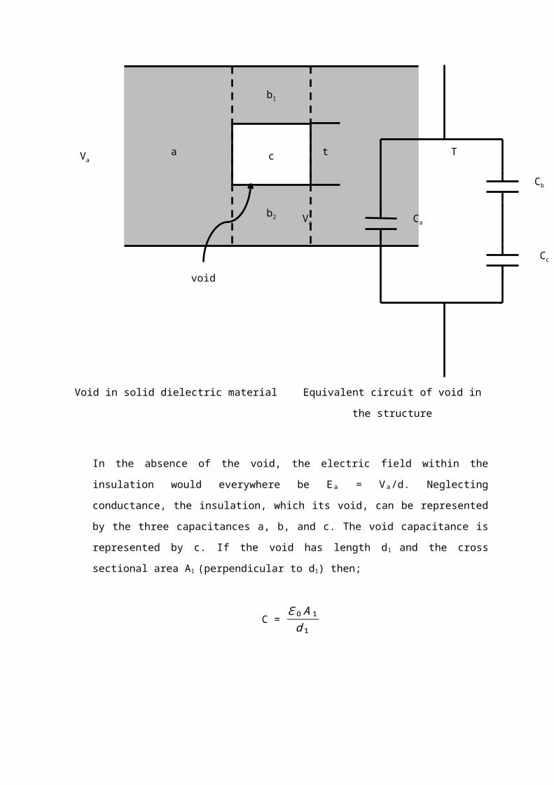
ii. A 3 stage voltage multiplier (Cockcroft-Walton)
iii. A 3-stage impulse generator

QUESTION 9
a) Explain the advantages of generating ac high voltage using cascade transformer as
compared to the normal step-up transformer.
ANSWER
Advantages
- Cheap
- Use less coil.
- Lack of insulation problem
- Small size
b) Explain the method to measure ac high voltage using capacitor voltage divider
& sphere gap.
ANSWER

i) Capacitor voltage divider
The use of capacitive voltage dividers with an electrostatic voltmeter is to eliminate
the errors due to harmonics.
The applied voltage V1 is given by,
ii) sphere gap
-Sphere gaps technique are reliable only for certain gap configurations.
-Normally, only sphere gaps are used. In certain casesuniform field gaps and rod gaps are also used, but theiraccuracy is less.
-The actual breakdown voltage Udat air density d may be found from the tabulated value, Udoby the following formula;


c) Explain the operation of Cockroft-Walton three stage multiplier for direct
current (dc) high voltage generation.
i) Used for higher voltages.
ii) Generate very high dc voltage from single supply transformer by extending
the simple voltage doubler circuit
ANSWER

d) With the aid of suitable diagrams, explain the principle of operation three
stages Mark impulse generator.
ANSWER
The 1st stage being replaced by a pulse transformer. For the trigger process, using
this transformer a voltage pulse with a polarity opposite to the charging voltage of
capacitor C1 is included resulting in an over voltage across the first stage spark gap
FS1. This over voltage causes the spark gap to break down and the Marx-generator
is erected in the usual manner.
As the spark gaps operate in the same way as in the free running mode, i.e. without
an additional trigger electrode, a longer lifetime of the spark gaps is to be expected.
QUESTION 10
a) Discuss in detail about the phenomenon starting with the information of thunderclouds
ANSWER
Terdapat banyak faktor-faktor yang menyumbang kepada pemebentukan atau
menumpuan cas di dalam awan. Secara ringkasnya semasa rebut petir, cas-cas
positif dan negative terpisah disebabkan oleh pengerakkan arus udara yang besar
berserta hablur ais pada bahagian atas awan dan kejadian pada bahagian bawah
awan. Pemisahan ini bergantung kepada ketinggian awan iatu di antara 200 ke 10
000m. suhu di dalam awan boleh mencapai nilai 1 ke 100 ˚C. Manakala voltan pula di

antara 107 ke 108 V dengan medan elektrik di antara 100kV/cm. Tenaga yang wujud
mungkin mencapai nilai 250kWh.
Adalah dipercayai bahawa kawasan arus awan bercas positif manakala bahagian
bawah arus bercas negative. Medan electric pada permukaan bumi boleh mencapai
nilai 300V/cm dibandingkan pada keadaan cuaca biasa (tanpa rebut petir) nilainya 1V/cm.
Disebabkan oleh kecerunan suhu, arus udara bergerak keatas sambil membwa
kelembapan dan titisan air. Suhu ketinggian 4kn ialah 0˚C dan pada ketinggian
12km pula -50˚C. titisan ait tidak akan membeku apabila mecapai suhu 0˚C
sebaliknya mebeku pada -40˚C dalam bentuk hablur ais yang membesar. Suhu
beku efektif adalah di antara -33 ke -40˚C.
Disebabkan beratnya, hablur ais yang tebentuk mula bergrek ke bawah. Pasa masa
yang sama titisan air yang ditiup ke atas oleh arus udara dan seterusnya titisan air
menjadi dingin melampau bergantung pada ketinggian. Oleh itu satu awan petir yang
dingin lampau bergerak ke atas dan satu hujan bergerak ke bawah.
Dalam masa penegrakan tersebut titisan air akan menjadi beku, mula-mula pada
bahagian luar titisan. Satu kelompang yang mengandungi air di tengahnya pun
terbentuk. Apabila air di dalam kelompang itu membeku, kelompang akan pecah
disebabkan oleh pengembangan yang berlaku seterusnya menghasilkan biji-
biji kecil ais yang membawa cas positif. Biji-biji ini kan di bawa oleh arus udara
kebahadian atas awan.
Hujan batu yang bergerak pula membawa cas negative yang sama bnyaknya. Oleh
itu, terbentuklah cas positif pada bahagian atas awan dan cas negative pada bahagian
bawah cas.
b) Briefly describe the followings:
i) Back flashover
ii) Ground flash density
iii) Insulation co-ordination
iv) Temporary overvoltage’s
c) A peak lighting current of 40kA has struck a ground wire a mid span (at the
middle of the transmission towers). If the wire surge impedance is given as

Z=500Ω, calculate the generated voltages at the point of strike. State the
assumption you made from this question
ANSWER
Anggap
i) Zs infinitiii) Tiada balikan voltan pada talian bumi
Zsetup: Z/2
V pada titi ukuran, V=IZ2
= 40 k×500
2
= 10 MV10.
Zl=500ΩZc=500Ω
I=40kA

QUESTION 11
a) Explain what is meant by the terms “T1/ T2 Impulse Wave” and outline the
method of lightning impulse voltage production in the laboratory.
ANSWER
An impulse voltage wave is a unidirectional voltage which rises rapidly to a maximum
value and then decays rather more slowly to zero as shown in the diagram below:
The wave shape is generally defined in terms of the time T1 and T2 in microsecond.
T1 is the time taken by the voltage wave to reach its peak value. i.e from 10% to 90% of
the voltage wave. T2 is the total time from the start of the wave to the instant when it has
declined to one half of its peak, i.e from start of the wave to 50% of the peak during decay.
T2T1
t
V
100%
90%
50%
10%

b) It is required to impulse test a 200pF, 500kV capacitor at twice its rated voltage
using a 50/250 µs impulse. A number of 0.01 µF, 100kV capacitors are available
and high voltage resistors can be constructed as required.
i) Design and sketch a suitable Marx multistage generator utilizing the maximum number of capacitor.
ANSWER
ii) Calculate the maximum peak voltage possible when each capacitor is
charged to its maximum value of 100kV.
Given
C1= 0.001µF, 100kV
C2 = 200pF, 500kV
T1 = 50µs
T2 = 250µs
ANSWER
Twice = 2(500kV)

Choose stages = 10
C1 = the Generator Capacitance
= 0.01µ
10
= 0.001µF
T1 = 50µs
50µ = 3 R1.[C 1.C 2C 1+C 2
]
50µ = 3 R1. [(0.001µ ) (200 p )(0.001 µ )+(200 p )
]
R1= 100kΩ
T2 = 0.7(R1+R2) (C1+C2)
250µ = 0.7(100k+R2) (0.001µ+200p)
R2 = 197.6kΩ
The DC Charging Voltage of 10 stages
V = 10 x 100k
V = 1MV
The Maximum Output Voltage
Vo = V
R 1.C 2 (α−β ).(e−αt 1−e−βt 1)
α=1
R 1.C 2β =
1R 2.C 1
= 1
(100k )(200 P) =
1(197.6k )(0.001 µ)
=50 x103 = 5.061 × 10³
Vo = 1 M
(100k× 200 p )(50k−5.061k).(e (−50 k )(50 µ)−e(−5.061 k)(50 µ))
= 767.7kV

QUESTION 12
a) Surge diverters (or lightning arrestors) generally consist of one or more spark gaps in series, together with one or more non-linear resistors in series.
ANSWERINSPIRING CREATIVE AND INNOVATIVE MINDS
Silicon Carbide (SiC) was the material most often used inthese nonlinear
resistor surge diverters.
Zinc Oxide (ZnO) is being used in most modern day. Surge diverters on
account of its superior volt-ampere characteristic. In fact the ZnO arrestor is
often used gap less, as its normal follow current is negligibly small.
The volt-ampere characteristics of SiC and of ZnO non-linearelements are
shown below for comparison with that of a linearresistor.
b) Discuss in detail about the lightning phenomenon starting with the formation of
thunderclouds.
An electrical phenomenon carries the concept of charges involvement. So two
types of charges are the reasons for the cloud to be considered as a cell. The
charges are positive type & negative type.
ANSWER

Figure shows the typical thundercloud structure.
Not all clouds are lightning cloud generator. It is only the cumulonimbus cloud type
that can generate lightning. The ice Splinter can be used to explain the electrification
of the cloud. The moistures and precipitation particles being is suspension in air and
due to upwards action of updraft, causing super cooling to take place and resulting
moisture to become ice.
The ionic migration of OH- & H- in the moisture built, leaving the OH-in the front and
H- being lighter are pulled out to settle in the outer layer. The resultant two-layer ice
structure split due to different rate of ice expansion ( the inner & the outer layer).
The splinters are basically of positive-charged & the negative-charged. The lighter
splinters are pulled upwards while the lighter negatively charged splinters settle at the
lower point of the cloud. If the electric field between the cloud & ground exceed the
dielectric strength of air streamers will appear and propogate towards the ground.
The last jump of this streamers to the ground result in upward streamers to move to
attach itself to the downwards-moving streamers. The attachment results in the
process of charges neutralization of the positive & negative charges. This is known as
return strike. It causes large currents to flow to the ground.