high voltage igbt modules (hv-igbt) - hy-line · high voltage igbt modules (hv-igbt) features...
TRANSCRIPT
4.01
56
4
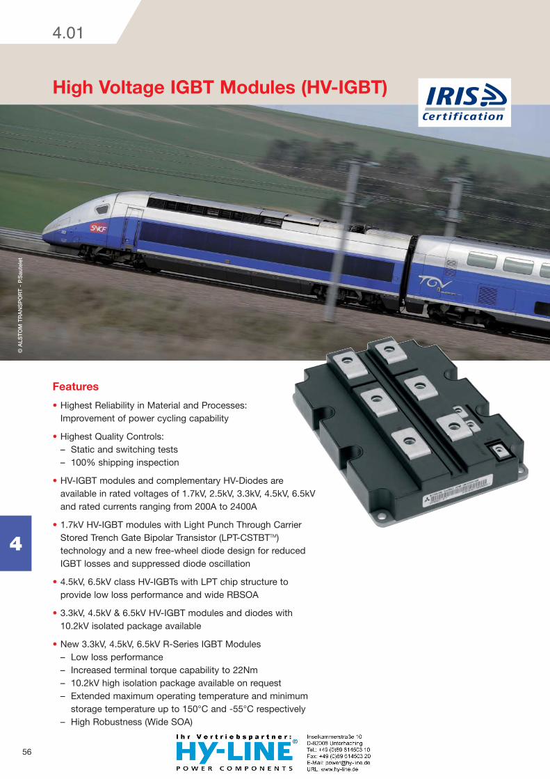
High Voltage IGBT Modules (HV-IGBT)
Features
Highest Reliability in Material and Processes: Improvement of power cycling capability
Highest Quality Controls: – Static and switching tests – 100% shipping inspection
HV-IGBT modules and complementary HV-Diodes are available in rated voltages of 1.7kV, 2.5kV, 3.3kV, 4.5kV, 6.5kV and rated currents ranging from 200A to 2400A
1.7kV HV-IGBT modules with Light Punch Through Carrier Stored Trench Gate Bipolar Transistor (LPT-CSTBTTM) technology and a new free-wheel diode design for reduced IGBT losses and suppressed diode oscillation
4.5kV, 6.5kV class HV-IGBTs with LPT chip structure to provide low loss performance and wide RBSOA
3.3kV, 4.5kV & 6.5kV HV-IGBT modules and diodes with 10.2kV isolated package available
New 3.3kV, 4.5kV, 6.5kV R-Series IGBT Modules – Low loss performance – Increased terminal torque capability to 22Nm – 10.2kV high isolation package available on request – Extended maximum operating temperature and minimum
storage temperature up to 150°C and -55°C respectively – High Robustness (Wide SOA)
© A
LST
OM
TR
AN
SP
OR
T -
P.S
aute
let
57
4
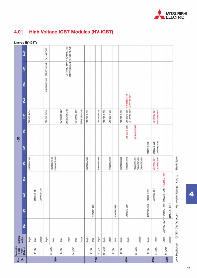
Line-up HV-IGBTs
4.01 High Voltage IGBT Modules (HV-IGBT)
I C (
A)
45
00
33
00
Gen
erat
ion
&
Bas
e P
late
M
ater
ial
Co
nfi
gu
-
rati
on
VC
ES
(V)
17
00
25
00
20
0
40
0
60
0
75
0
80
0
90
0
10
00
1
20
0
15
00
1
60
0
18
00
2
40
0
Si
ngle
CM
800H
A-34
H
CM
1200
HA-3
4H
G1 (C
u)
Dual
CM
600D
Y-34
H
Ch
oppe
r
CM
600E
2Y-3
4H
Si
ngle
CM12
00HC
-34H
CM16
00HC
-34H
CM
1800
HC-3
4H
CM24
00HC
-34H
G3 (A
lSiC
)
Dual
CM
800D
Z-34
H
CM80
0DZB
-34N
2
G4 (C
u)
Dual
CM12
00DB
-34N
2
CM
1200
HCB-
34N
2
CM
1800
HC-3
4N2
CM24
00HC
-34N
2
Si
ngle
CM18
00HC
B-34
N2 C
M24
00HC
B-34
N2
G4 (A
lSiC
)
Du
al
CM
1200
DC-3
4N2
Ch
oppe
r
CM12
00E4
C-34
N2
Si
ngle
CM
800H
A-50
H
CM
1200
HA-5
0H
G1 (C
u)
Du
al
CM
400D
Y-50
H
G2
(Cu)
Si
ngle
CM
800H
B-50
H
CM
1200
HB-5
0H
G3
(AlS
iC)
Sing
le
CM
1200
HC-5
0H
Sing
le
CM80
0HA-
66H
CM12
00HA
-66H
G1
(Cu)
Du
al
CM
400D
Y-66
H
G2 (C
u)
Sing
le
CM80
0HB-
66H
CM12
00HB
-66H
CM40
0HG-
66H3
CM80
0HC-
66H
CM
1000
HC-6
6R4
CM12
00HC
-66H
CM
1500
HC-6
6R4
Si
ngle
CM
1200
HG-6
6H3 C
M15
00HG
-66R
1,3,
4
CM80
0E2C
-66H
CM10
00E4
C-66
R4
G3 (A
lSiC
)
Ch
oppe
r
CM
800E
4C-6
6H
CM
800E
6C-6
6H
G2 (C
u)
Sing
le
CM
400H
B-90
H CM
600H
B-90
H
CM
900H
B-90
H
CM60
0HG-
90H3
CM
800H
C-90
R1,4
CM90
0HC-
90H
CM
1200
HC-9
0R4
G3 (A
ISiC
) Si
ngle
CM80
0HG-
90R3,
4 CM
900H
G-90
H3
CM12
00HG
-90R
3,4
Si
ngle
CM
200H
G-13
0H3
CM40
0HG-
130H
3 CM
600H
G-13
0H3
CM75
0HG-
130R
3,4
G3
(AlS
iC)
Ch
oppe
r
CM40
0E4G
-130
H3
65
00
1 Un
der D
evel
opm
ent
2
CSTB
TTM C
hip
Tech
nolo
gy
3 Hi
gh Is
olat
ion
Pack
age
(10.
2kV r
ms)
4
New
R-S
erie
s

Type
Number
VCES (V)
Typ. Max.
IGBTRth(j-c)
(K/W)
Max.
DiodeRth(j-c)
(K/W)
Max.
Rth(c-f)
(K/W)
Max.
Electrical
Characteristics
Package-
No.
Package
Symbol
Maximum
Ratings
IC (A)
Viso (V)
VCE(sat)
@ Tj = 25°C(V)
Vf
@ Tj = 25°C(V)
Typ.
Err
@ Tj = 125°C(J/P)
Typ.
Eon
@ Tj = 125°C(J/P)
Typ.
Eoff
@ Tj = 125°C(J/P)
Typ.
Free Wheel
Diode
Thermal & Mechanical
Characteristics
58
4
4.01 High Voltage IGBT Modules (HV-IGBT)
1700 Volt HV-IGBT Modules
CM600DY-34H 1700 600 4000 2.75 3.58 0.28 0.15 2.4 0.09 0.0180 0.056 0.016 HV2
CM800DZ-34H 1700 800 4000 2.60 3.30 0.35 0.26 2.3 0.12 0.0200 0.034 0.016 HV2
D CM800DZB-34N 1700 800 4000 2.10 2.70 0.30 0.20 2.2 0.18 0.0240 0.036 0.018 HV2
CM1200DC-34N 1700 1200 4000 2.15 2.80 0.38 0.36 2.6 0.22 0.0190 0.042 0.016 HV10
CM1200DB-34N 1700 1200 4000 2.15 2.80 0.38 0.36 2.6 0.22 0.0180 0.04 0.016 HV10
CM800HA-34H 1700 800 4000 2.75 3.58 0.30 0.30 2.4 0.15 0.0135 0.042 0.012 HV1
CM1200HA-34H 1700 1200 4000 2.75 3.58 0.45 0.45 2.4 0.22 0.0090 0.028 0.008 HV1
CM1200HC-34H 1700 1200 4000 2.50 3.25 0.40 0.44 2.25 0.18 0.0120 0.020 0.010 HV1
CM1200HCB-34N 1700 1200 4000 2.05 2.70 0.43 0.32 2.2 0.29 0.0140 0.021 0.010 HV7
CM1600HC-34H 1700 1600 4000 2.60 3.30 0.54 0.58 2.3 0.22 0.0100 0.017 0.008 HV1
H CM1800HC-34H 1700 1800 4000 2.40 3.10 0.59 0.67 2.2 0.26 0.0080 0.013 0.007 HV4
CM1800HC-34N 1700 1800 4000 2.15 2.80 0.55 0.56 2.6 0.28 0.0125 0.028 0.011 HV12
CM1800HCB-34N 1700 1800 4000 2.00 2.60 0.56 0.50 2.1 0.44 0.0090 0.013 0.007 HV4
CM2400HC-34H 1700 2400 4000 2.60 3.30 0.81 0.87 2.3 0.33 0.0070 0.012 0.006 HV4
CM2400HC-34N 1700 2400 4000 2.15 2.80 0.64 0.84 2.6 0.38 0.0095 0.021 0.008 HV12
CM2400HCB-34N 1700 2400 4000 2.10 2.70 0.65 0.70 2.20 0.50 0.0080 0.012 0.006 HV4
E2 CM600E2Y-34H 1700 600 4000 2.75 3.58 0.28 0.15 2.40 0.09 0.0180 0.056 0.016 HV13
E4 CM1200E4C-34N 1700 1200 4000 2.15 2.80 0.38 0.36 2.60 0.22 0.0190 0.042 0.016 HV12
2500 Volt HV-IGBT Modules
D CM400DY-50H 2500 400 6000 3.20 4.16 0.50 0.40 2.90 0.11 0.036 0.072 0.016 HV3
CM800HA-50H 2500 800 6000 3.20 4.16 1.00 0.80 2.90 0.21 0.018 0.036 0.008 HV5
CM800HB-50H 2500 800 6000 2.80 3.64 0.80 0.86 2.50 0.33 0.012 0.024 0.008 HV7
H CM1200HA-50H 2500 1200 6000 3.20 4.16 1.50 1.20 2.90 0.31 0.012 0.024 0.006 HV6
CM1200HB-50H 2500 1200 6000 2.80 3.64 1.20 1.29 2.50 0.45 0.008 0.016 0.006 HV4
CM1200HC-50H 2500 1200 6000 2.80 3.60 1.30 1.20 2.50 0.45 0.0085 0.017 0.006 HV4
Circuit Diagrams
D H E2 E4 E6
For detailed connections please refer data sheet.

Type
Number
VCES (V)
Typ. Max.
IGBTRth(j-c)
(K/W)
Max.
DiodeRth(j-c)
(K/W)
Max.
Rth(c-f)
(K/W)
Max.
Electrical
Characteristics
Package-
No.
Package
Symbol
Maximum
Ratings
IC (A)
Viso (V)
VCE(sat)
@ Tj = 25°C(V)
Vf
@ Tj = 25°C(V)
Typ.
Err
@ Tj = 125°C(J/P)
Typ.
Eon
@ Tj = 125°C(J/P)
Typ.
Eoff
@ Tj = 125°C(J/P)
Typ.
Free Wheel
Diode
Thermal & Mechanical
Characteristics
59
4
Preliminary Data For detail test conditions please refer to data sheets.
4.01 High Voltage IGBT Modules (HV-IGBT)
3300 Volt HV-IGBT Modules
D CM400DY-66H 3300 400 6000 4.40 5.72 0.67 0.40 3.30 0.17 0.036 0.072 0.016 HV3
CM400HG-66H 3300 400 10200 3.30 0.59 0.52 2.80 0.30 0.027 0.0525 0.018 HV9
CM800HA-66H 3300 800 6000 4.40 5.72 1.60 0.80 3.30 0.33 0.018 0.036 0.008 HV5
CM800HB-66H 3300 800 6000 3.80 4.94 1.20 0.96 2.80 0.47 0.012 0.024 0.008 HV7
CM800HC-66H 3300 800 6000 3.30 4.20 1.10 1.05 2.80 0.60 0.013 0.025 0.008 HV7
CM1000HC-66R 3300 1000 6000 2.45 1.85 1.65 2.15 1.20 0.012 0.0225 0.009 HV14
H CM1200HA-66H 3300 1200 6000 4.40 5.72 2.00 1.20 3.30 0.50 0.012 0.024 0.006 HV6
CM1200HB-66H 3300 1200 6000 3.80 4.94 1.80 1.44 2.80 0.70 0.008 0.016 0.006 HV4
CM1200HC-66H 3300 1200 6000 3.30 4.20 1.60 1.55 2.80 0.90 0.0085 0.017 0.006 HV4
CM1200HG-66H 3300 1200 10200 3.30 1.60 1.55 2.80 0.90 0.009 0.0175 0.006 HV8
CM1500HC-66R 3300 1500 6000 2.45 2.75 2.45 2.15 1.75 0.008 0.015 0.006 HV15
CM1500HG-66R 3300 1500 10200 2.45 2.75 2.45 2.15 1.75 0.0085 0.0155 0.006 HV16
E2 CM800E2C-66H 3300 800 6000 3.80 4.94 1.20 0.96 2.80 0.47 0.013 0.025 0.008 HV4
E4
CM800E4C-66H 3300 800 6000 3.30 1.10 1.05 2.80 0.60 0.013 0.025 0.006 HV4
CM1000E4C-66R 3300 1000 6000 2.45 1.85 1.65 2.15 1.20 0.012 0.0225 0.007 HV15
E6 CM800E6C-66H 3300 800 6000 3.30 4.20 1.10 1.05 2.80 0.60 0.013 0.025 0.008 HV4
4500 Volt HV-IGBT Modules
CM400HB-90H 4500 400 6000 3.00 3.90 2.00 1.20 4.00 0.28 0.021 0.042 0.015 HV7
CM600HB-90H 4500 600 6000 3.00 3.90 2.80 1.80 4.00 0.42 0.0135 0.027 0.010 HV7
CM600HG-90H 4500 600 10200 3.45 2.80 1.70 4.80 0.67 0.0165 0.033 0.009 HV11
CM800HC-90R 4500 800 10200 3.50 3.15 2.60 2.60 1.50 0.015 0.0285 0.009 HV14
H
CM800HG-90R 4500 800 10200 3.50 3.15 2.60 2.60 1.50 0.016 0.0295 0.009 HV17
CM900HB-90H 4500 900 6000 3.00 3.90 4.00 2.70 4.00 0.88 0.009 0.018 0.007 HV4
CM900HC-90H 4500 900 6000 3.45 4.20 2.50 4.80 1.00 0.0105 0.021 0.006 HV4
CM900HG-90H 4500 900 10200 3.45 4.20 2.50 4.80 1.00 0.011 0.022 0.006 HV8
CM1200HC-90R 4500 1200 6000 3.50 4.70 3.85 2.60 2.25 0.010 0.019 0.006 HV15
CM1200HG-90R 4500 1200 10200 3.50 4.70 3.85 2.60 2.25 0.0105 0.0195 0.006 HV16
6500 Volt HV-IGBT Modules
CM200HG-130H 6500 200 10200 4.5 1.50 1.20 4.0 0.70 0.042 0.066 0.018 HV9
H
CM400HG-130H 6500 400 10200 4.5 3.00 2.70 4.0 1.40 0.021 0.033 0.009 HV11
CM600HG-130H 6500 600 10200 4.5 4.50 4.30 4.0 2.00 0.014 0.022 0.006 HV8
CM750HG-130R 6500 750 10200 3.9 4.10 4.60 3.0 1.85 0.012 0.022 0.006 HV16
E4 CM400E4G-130H 6500 400 10200 4.5 3.00 2.70 3.8 1.40 0.021 0.033 0.009 HV8

60
4
Package HV1 Package HV2
Package HV3 Package HV4
Dimensions in mm
Package HV5 Package HV6
4.01 High Voltage IGBT Modules (HV-IGBT)
61
4
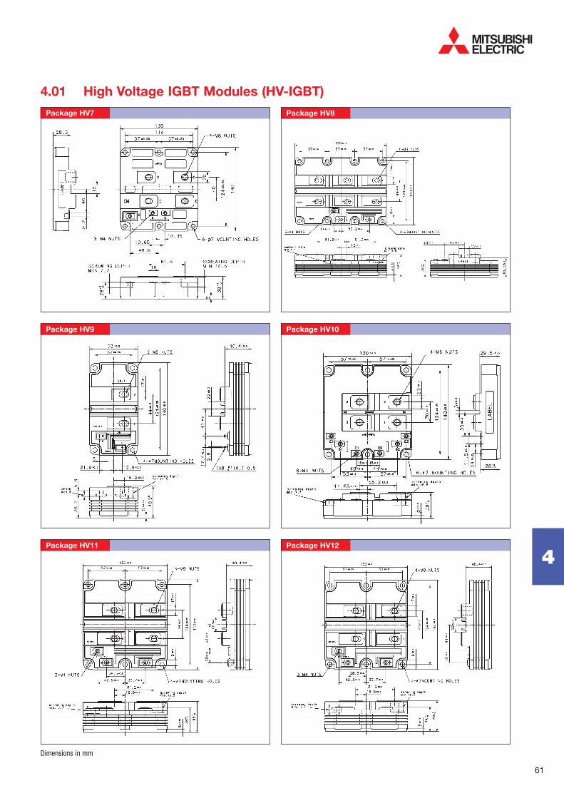
4.01 High Voltage IGBT Modules (HV-IGBT)
Package HV7 Package HV8
Package HV9 Package HV10
Package HV11 Package HV12
Dimensions in mm

62
4
Package HV13 Package H14
Package HV15 Package HV16
Dimensions in mm
Package HV17 Notes
4.01 High Voltage IGBT Modules (HV-IGBT)

63
4
4.02
High Voltage Diode Modules
Features
Complementary to HV-IGBT modules for multilevel inverter designs
Wide creepage distance between main terminals
Ease of both installation and connection allows application equipment to be reduced in dimensions and weight
Circuit Diagrams
H D
For detailed connections please refer data sheets.
© A
LST
OM
TR
AN
SP
OR
T

64
4
4.02 High Voltage Diode Modules
VCES
(V)
IC (A)
200 250 300 400 600 900 1000 1200 1500 1800
G3 (AlSiC) Single RM1800HE-34S
1700
G3 (Cu) Dual RM1200DB-34S
G1 (Cu) Dual RM400DY-66S RM600DY-66S
3300 G2 (Cu) Dual RM1200DB-66S G3 (AlSiC) Single RM1200HE-66S
Dual RM400DG-66S1 RM1000DC-66F2 RM1200DG-66S1 RM1500DC-66F2
G2 (Cu) Dual RM900DB-90S 4500
G3 (AlSiC) Single RM600HE-90S
Dual RM300DG-90S1 RM400DG-90F1,2
6500 G3 (AlSiC) Dual RM200DG-130S1 RM250DG-130F1,2 RM600DG-130S1
Generation
& Base Plate
Material
Con-
figu-
ration
1 High Isolation Package (10.2kVrms) 2 New R-Series
Line-up HV-Diode Modules
Type Number VRRM (V)
IDC
(A)Viso (V)
VFM (V)
@ Tj = 25°C
IFSM
(A)
Qrr
(μC)Typ.
Err
(J/P)Typ.
trr(μs)Max.
Rth(j-c)
(K/W)Rth(c-f)
(K/W)
Electrical CharacteristicsMaximum Ratings Thermal & Mechanical
CharacteristicsPackage-
No.
Package
Symbol
1700 Volt HV-Diode Modules
D RM1200DB-34S 1700 1200 4000 20800 2.10 0.30 420 0.85 0.020 0.024 RM6
H RM1800HE-34S 1700 1800 6000 9600 2.90 0.40 600 0.8 0.022 0.017 RM2
3300 Volt HV-Diode Modules
RM400DY-66S 3300 400 6000 3200 3.75 0.15 200 0.75 0.072 0.036 RM1
RM400DG-66S 3300 400 10200 3200 2.80 0.30 270 1.00 0.054 0.048 RM4
RM600DY-66S 3300 600 6000 4800 3.75 0.23 300 0.75 0.048 0.024 RM1
D RM1000DC-66F 3300 1000 6000 9400 2.20 1.20 1150 0.75 0.024 0.026 RM5
RM1200DB-66S 3300 1200 6000 9600 3.00 0.75 850 0.75 0.018 0.016 RM3
RM1200DG-66S 3300 1200 10200 9600 3.00 0.90 800 1.00 0.018 0.016 RM4
RM1500DC-66F 3300 1500 6000 14000 2.20 1.85 1700 0.75 0.016 0.0175 RM5
H RM1200HE-66S 3300 1200 6000 9600 3.20 0.85 900 1.40 0.020 0.015 RM2
4500 Volt HV-Diode Modules
RM300DG-90S 4500 300 10200 2400 4.80 0.33 250 1.00 0.066 0.048 RM4
D RM400DG-90F 4500 400 10200 3400 2.55 0.75 580 0.90 0.0585 0.048 RM4
RM900DB-90S 4500 900 6000 6400 4.00 0.70 650 0.90 0.020 0.016 RM3
H
RM600HE-90S 4500 600 6000 4800 4.80 0.62 600 0.90 0.039 0.015 RM2
RM900HC-90S 4500 900 6000 7200 4.80 1.00 750 1.00 0.021 0.016 RM3
6500 Volt HV-Diode Modules
RM200DG-130S 6500 200 10200 1600 4.00 0.70 300 1.00 0.066 0.048 RM4
D RM250DG-130F 6500 200 10200 2350 3.30 0.80 340 0.60 0.0675 0.048 RM4
RM600DG-130S 6500 600 10200 4800 4.00 2.00 900 1.00 0.022 0.016 RM4
For detail test conditions please refer to data sheets.

65
4
4.02 High Voltage Diode Modules
Package RM1 Package RM2
Package RM3 Package RM4
Package RM5 Package RM6
Dimensions in mm
66
4
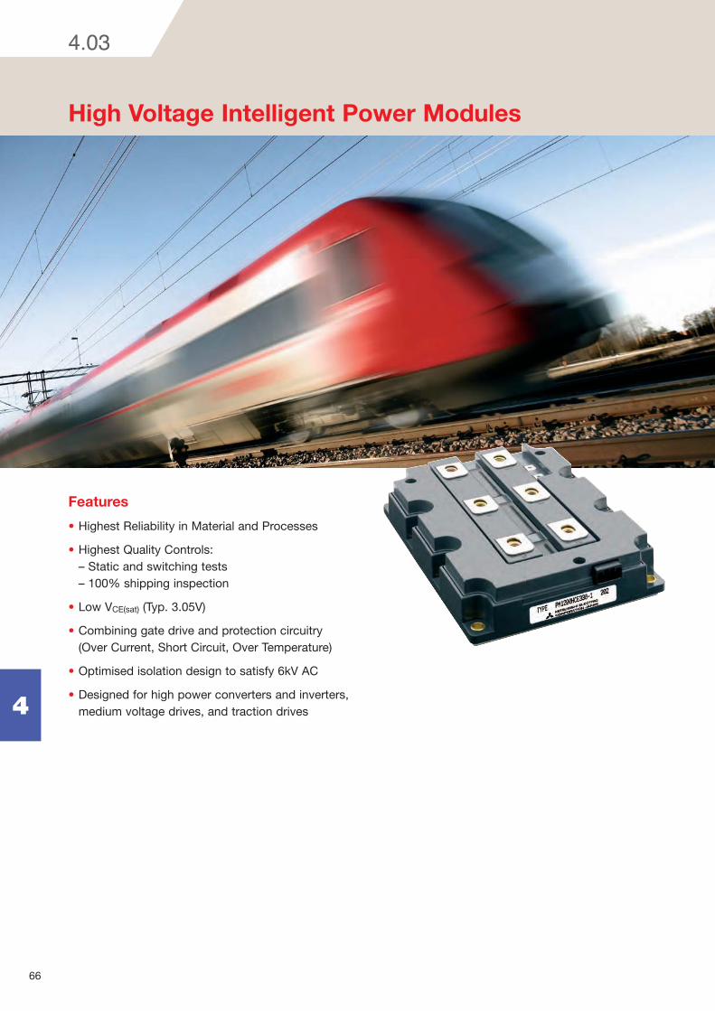
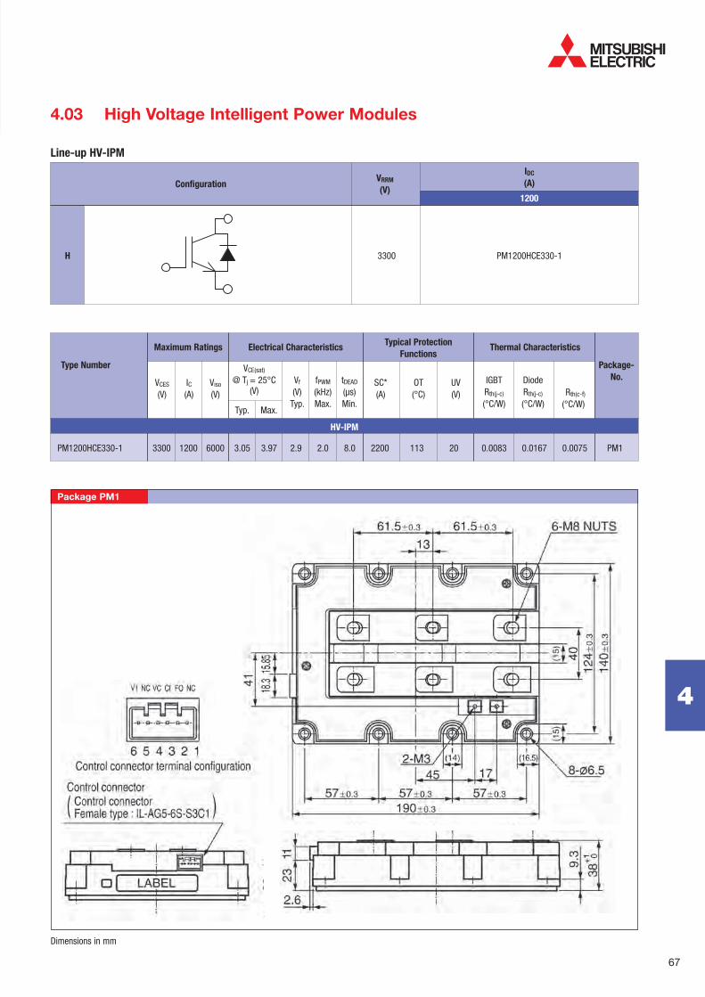
High Voltage Intelligent Power Modules
Features
Highest Reliability in Material and Processes
Highest Quality Controls: – Static and switching tests – 100% shipping inspection
Low VCE(sat) (Typ. 3.05V)
Combining gate drive and protection circuitry (Over Current, Short Circuit, Over Temperature)
Optimised isolation design to satisfy 6kV AC
Designed for high power converters and inverters, medium voltage drives, and traction drives
4.03
67
4
IDC
(A)
1200
Configuration
Maximum Ratings
Typ. Max.
IC (A)
VCE(sat)
@ Tj = 25°C(V)
Electrical Characteristics
Package-
No.fPWM
(kHz)Max.
Vf
(V)Typ.
tDEAD
(μs)Min.
IGBTRth(j-c)
(°C/W)
DiodeRth(j-c)
(°C/W)Rth(c-f)
(°C/W)
SC*(A)
OT(°C)
UV(V)
Thermal CharacteristicsTypical Protection
Functions
Type Number
HV-IPM
PM1200HCE330-1 3300 1200 6000 3.05 3.97 2.9 2.0 8.0 2200 113 20 0.0083 0.0167 0.0075 PM1
Viso (V)
VCES (V)
Package PM1
H 3300 PM1200HCE330-1
4.03 High Voltage Intelligent Power Modules
VRRM
(V)
Line-up HV-IPM
Dimensions in mm
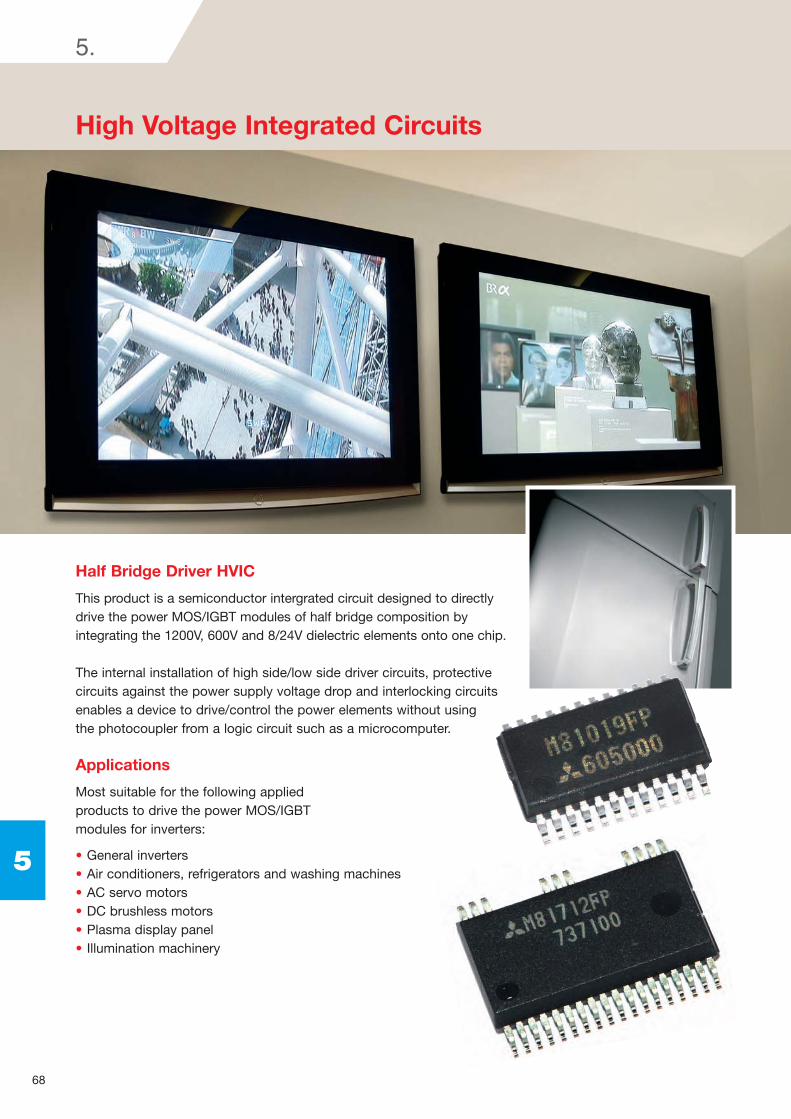
Half Bridge Driver HVIC
This product is a semiconductor intergrated circuit designed to directly drive the power MOS/IGBT modules of half bridge composition by integrating the 1200V, 600V and 8/24V dielectric elements onto one chip.
The internal installation of high side/low side driver circuits, protective circuits against the power supply voltage drop and interlocking circuits enables a device to drive/control the power elements without using the photocoupler from a logic circuit such as a microcomputer.
Applications
Most suitable for the following applied products to drive the power MOS/IGBT modules for inverters:
General inverters Air conditioners, refrigerators and washing machines AC servo motors DC brushless motors Plasma display panel Illumination machinery
High Voltage Integrated Circuits
68
5
5.

69
5
5. High Voltage Integrated Circuits
Typename
Floating
supply voltage
(V)
Output
current
(A)
Generation
Number
of input-
signals
Driving
method
3 Phase 2x3Ø
Half Bridge
Dual
Half Bridge
Single
High side1
Dual
Low side1x2 3rd
3rd
3rd
3rd
3rd
4th
4th
4th
3rd
2nd
1x2
1
2
2
Dead-time
controlFunctions
Package
outline
UV: Under Voltage / IL: Inter Lock / NF: Input Noise Filter / SC: Short Current / SD: Shut Down /
SS: Soft Shutdown / FO: Failure Output / FOIN: FO Input / FORST: FO reset / CFO: Capacitor FO
M81712FP 600 0.2/-0.5 Input Signal UV, IL, NF 28X9R
M81706AFP 600 0.2/-0.35 Input Signal UV, IL 8P2S
M81708FP 600 0.2/-0.35 Input Signal UV, IL 16P2N
M81719FP 600 0.2/-0.35 Input Signal UV, NF 8P2S
M81720FP 600 0.2/-0.35 Input Signal UV, IL, NF 8P2S
M81721FP 600 1.0 Input Signal UV, NF, SC, FO, FORST, FOIN 24P2Q
M81019FP 1200 1.0 Input Signal UV, NF, SC, FO, FORST, FOIN 24P2Q
M81700FP 600 2.5 Input Signal UV, IL, SD 16P2N
M81701FP 600 2.5 Input Signal UV, IL 16P2N
M81702FP 600 2.5 Input Signal UV, SD 16P2N
M81703FP 600 2.5 Input Signal UV 16P2N
M81709FP 600 2.5 Input Signal UV, IL 16P2N
M81722FP 600 3.0 Input Signal UV, NF 8P2S
M81736FP 600 0.2/-0.35 Input Signal UV, IL compatible with M81706AFP 8P2S
M81735FP 600 0.5 Input Signal UV, IL 16P2N
M81713FP 600 0.5 Internal UV 8P2S
M81734FP 600 0.5 Internal UV compatible with M81713FP 8P2S
M81707FP 600 0.1 Input Signal UV 16P2N
M81731FP 600 3.0 Input Signal UV, NF 16P2N
M81723FP 600 0.13/-0.1 Input Signal UV compatible with M81707FP 16P2N
M81737FP 600 0.2 Input Signal UV 16P2N
M81711FP 24 1.01/-0.8 Low active 8P2S
M81716FP 24 1.01/-0.8 High active 8P2S
M81705FP 600 0.15/-0.13 UV 8P2S
M81725FP 600 3.0 UV, NF 8P2S

70
5
5. High Voltage Integrated Circuits
Package 28X9R (28pin 450mil SSOP)
Package 8P2S (8pin 225mil SOP) Package 16P2N (16pin 300mil SOP)
Package 24P2Q (24pin 300mil SSOP)
Notes
Dimensions in mm