high voltage dc transmission prof. s. n. singh …textofvideo.nptel.ac.in/108104013/lec36.pdf ·...
TRANSCRIPT

High Voltage DC Transmission
Prof. S. N. Singh
Department of Electrical Engineering
Indian Institute of Technology, Kanpur
Module No. # 07
Lecture No. # 02
HVDC Light/Plus
So, welcome to lecture number 2 of this module module number 7, and in this module, I will
discuss the HVDC Light and also sometimes called as HVDC plus. Basically, this HVDC
light, the nick name or trade mark given by ABB; and HVDC plus is given by Siemens. So,
but the technology and concept is the same, that is why I will be using in this presentation as
HVDC light.
So, to start with let us see, what are the various problems in HVDC in a conventional HVDC
transmission system? And to you can see, the mostly the HVDC transmission system is used
for the long distance point to point transmission.
(Refer Slide Time: 00:49)
No doubt, we saw also that we can go for the multi terminal HVDC links or transmission
system, where we can tap the power in between, not it is one to one, so but it is again

becomes very complex and also we have the limited terminals like whenever you are adding
more than two converters, you are you doing any extra convertor, then it becomes multi
terminal HVDC. So, already in the previous lecture, we saw this multi terminal DC link. So,
it is said that it is a mostly used for the long distance, point to point transmission, although
some people may argue that it is not only for long distance, bulk power long point to point
transmission.
But now-a-days HVDC links are also used, and they are known as back to back connections,
they are very near to each other, and the purpose of this HVDC link is to control the power
from one region to another region, one system to another system or can provide the
asynchronous connection between the two systems, two regions as well. But in the early,
when thus people were talking about the long distances of HVDC applications, they were
mostly concerned about the transmitting bulk amount of power from one region to another
region, that is why it is said that it is mostly used for the long distance point to point
transmission, but it is now not so.
Now, we are also using back to back connections that as I said to control the power from one
area to another area, and also the sometime the HVDC system are also used to stabilize the
AC systems. Normally, they are the modulating the power and that is why AC, DC
transmission systems are running parallel. So, we know the point to point, because if you are
going to tap the power in between, then you require some extra converter, and also you have
to change the control philosophy, which we saw in the MTDC transmission system.
Another problem in conventional HVDC technology, that it requires the fast communication,
channels between the two stations or the three stations. Whenever you are having a multi
terminal, then you require the communication channel between all the sub stations or
converter stations. Why it is fast because, we saw the control characteristic in our control
philosophy, that that module we saw that what will be the characteristics of the rectifier, what
will be the characteristics of the inverter, they are the different.
So, once is operating in either as I say, thus it can operate you know rectifier is there, so it can
operate in the two modes, one can be your CIA mode, that is a constant ignition angle control,
that is a alpha minimum control or it can operate in the constant current mode. Similarly, the
inverter side, it can operate in this control mode that is CEA mode, that is a constant
extinction angle control, as well as it can also operate it in the constant current mode. In the

constant current mode also there in a inverter side, people are also argue that we can add the
constant voltage or a constant beta control, especially at this connection of this CC and CA,
where we require due to the various region, already we had discussed it, in our previous
modules.
So, we require that if, one converter station is working for one dedicated to voltage control or
current control or there will be taking care of voltage current or voltage vice versa. And also
we require a dedicated control that is what will be the current margin, as we known in this
conventional HVDC, the main concern, that we are using the constant current source
convertors, this CSC the current is basically, maintained constant and voltage is keep on
varying varying and thereby we are controlling the power.
So, this is a second problem in classical HDVC technology, another that is it is a large
reactive power support at the both the station; we know although this is the DC system does
not require any reactive power support, and the DC line as well as say. But, at the converter
stations and already we have proved that, in the ideal case already it has been proved, that the
power factor is equal to your cos alpha cosα , and alpha is the delay angle of the converter
station.
So, now we can find, if the alpha you are keep on delaying you are changing the voltage, and
cos alpha is a directly related to the DC voltage and the power is controlled by the DC
voltage. Once your power is controlling from either reversing or zero to certain value you are
going, the alpha is changed, once alpha is changed what is happening, then your power factor
requirement at the converter station is going to be high.
So, in the thumb rule normally people say that if its 100 mega watt HVDC line is there, and
you require at least 60 percent reactive power support at the both the terminal station;
terminals means two terminal, then you are having a rectifier and inverter, so you have to put.
So, huge reactive power support is required, that is basically to take care of the voltage
variation of the converters.
Then you have to put that is installation and again it is become very very bulky, and a station
becomes very very large, because we have to put a huge reactive power support, and
especially it is a capacitive support, we require at that end. Third thats in a conventional
HVDC technology in the beginning we started using the thyristors, and you know the
thyristors are basically, the line commutated converters, we can have and you know the

commutative means once you are going to turn it off, you have to make this is a primary
requirement of the thyristors, if you want to turn it off, the current flowing through the
thyristors should be zero.
So, in the normal way, it is keep on flowing the constant current, so you cannot turn it off. So,
to make it turn off the current should be zero, and the voltage across that thyristor should be
the reverse. So, to make current zero, we can use some auxiliary circuits and based on that we
can make some way, that we can make the zero, across this and then we can turn off the
thyristors. So, the conventional thyristors are valves, valves means is a series of the thyristors,
in the series and parallel make certain voltage level and the current carrying capacity, because
one thyristor unit is not able to provide complete support for that rating of the your HVDC
station.
So, we can use the valves and valves means, that we can use the series or the thyristors as
well as the parallel to make the particular rating, so and they are use the line commutate
convertors. Some other concern about HVDC already explained that is also, in the
conventional HVDC system, they introduce harmonics and not only the normal harmonics,
characteristics harmonics they also introduce the uncharacteristic harmonics.
Characteristics harmonics, if you remember this I already discussed, this NP plus minus one
np±1 those are even though current harmonics, then DC side also we are also having NP
the p is number of pulses, N is number of integer, so in the DC side also we are having some
harmonics. So, we require the filters for those and already in the AC side that for current
harmonics we use, if it is a 6 pulse convertor we use the 5th and 7th harmonics and filters
also 9th and 11th harmonics filters are used.
At the same time, they provide some reactive power support as well as the providing the
minimum impedance path to that one. So, this is the filters are used and it is very bulky and
also require the huge space. So, the harmonics and other concern are these major concerns,
the cost and other things are keep on declining, so cost was also in beginning concern, but
again thanks to the power electronics development and so on, so forth.
The costs are declining and in the future again in break even, when the AC and DC may go
down presently, it may be 6 to 700 kilometers, but it may again in future it may go down. So,
to avoid all these problems this conventional HVDC system, the HVDC light or HVDC plus,
again I want to re trade that, HVDC light the trade name given by ABB HVDC, plus it is a

name given by the Siemens, but the concept is the same. And both are using now instead of
the CSC that is a current source convertors, now they are going to replace these by using the
voltage source convertors, and we know the advantage and disadvantage of the current source
and the voltage source convertors well, I talk in the beginning, of this module 1 or module 2
there.
So, what changes they are doing, in this the basic change that the power transmission through
the HVDC utilizing the voltage source convertor as I just mentioned, and they are using the
IGBTs. IGBTs is nothing but, insulated gate bipolar transistors, now just see here it is a
transistor technology, however in the conventional, we are using the thyristor technology both
are different. So, using this which is the extinguishes the current more faster, and the less
energy loss than the GTOs and GTOs are gate turn off thyristors.
So, this is another grade of a thyristors, the conventional thyristors you cannot turn it off by
simple giving the gate pulse, you have to make the current across the flowing through the
thyristor should be zero in the conventional thyristor. But, in the GTOs by putting the
negative gate pulse, you can turn it off even though the current is flowing full capacity,
current flowing through the GTOs. But, you have require some of the circuits, because there
will be some transient your suddenly the current extinguishes, so that we use some extra
circuit to minimize those transients.
So, this HVDC light, the basic concept, the CSC convertors, it is a current source convertors
are replaced with the voltage source convertor. And they are utilizing the IGBTs that is a
insulated gate pole transistor, so the major difference here, that the transistors are used rather
than thyristors.

(Refer Slide Time: 10:00)
So, it is again that why here, I have written the HVDC light or plus, that is why here I am
right now using both, but in the some of my presentation we define only HVDC light,
because as we find more literature on the HVDC light compared to the HVDC plus. So, but,
again as I said the, they are using the voltage source convertors the VSC of HVDC.
If you see, the first HVDC light, the pilot transmission for the 3 megawatt only it was very
small, it was pilot project 3 megawatt and the plus minus ± 10 kilo volt in the march 1997,
it was established in the Sweden and the plus minus plus minus ± 10 KV as indicates, it is
a bipolar. And the bipolar that is why it is one is operating on the positive polarity, and
another is operating on the negative polarity.
And the voltage level between these two poles, it is a 20 KV, because from the 0 is a 10 KV
from below the 0 it is a minus 10 KV. The first commercial project, because this was the pilot
and the testing project. So, the first commercial project basically, just came into the practice
in 1999, and this was having the carrying the 50 megawatt, and that it is a plus minus ± 80
KV, you can see from here, the summary or the various projects commercial projects, it is in
table written in table.
This see this is nothing but, this is a Gotland, Sweden project, the Gotland is one island
already I explained this in the beginning of the this HVDC course. That the Gotland is Island
of the Sweden, which is almost it is a 70 kilo meters away from the main land, and that is and
it is this provided this HVDC light project, and it was commission in 1999, it is started

operating in 1999. So, current carrying capacity this is power capacity was 50 mega watts and
the voltage level was plus minus ± 80 KV means, again it is a bipolar. The distance here,
you can see it is a 70 kilo meters, it was used as a sea cable and it is a two cables are used,
because it is having the bipolar. So, two cables one is negative, another positive it is operating
and it connects even the wind farm to the load center, because that Island is having the full of
wind potential, and that is connected through this that cables, and that is sea cable.
Second project of it is there is so many smaller and smaller projects also came in, the Europe
as well as in other part of the world, but the here it is listed those are the bigger projects, and
bigger commercial projects here. So, this another is called the direct link that is in Australia,
and it was commissioned in 2002, and it was carrying 3 into 60, because the 3 lines were
there.
So, why it is that one bipolar is having 60, here you where using this 50, so here you can say
3 means, we are having the 3 bipolar operation of this 60 each means the total capacity, that is
flowing it is your 180 megawatt. And again the voltage level was plus minus 80 KV between
the 2 bipoles, that is why here you can see here it is a 6 we have multiplied, because we are
having the 6 cables, one cable for positive, one cable for negative, so it is one bipolar. So,
similarly we are having 3, so it is a 6 multiplied by 65 and it connects basically, the two
regional electricity markets and here, this length is a 65 kilo meters.
Another which was basically established, this is a cross sound cable, in US 2002 again, and it
was having huge power that is 330 megawatt and the voltage level also you can see, it is a
plus or minus 150 voltage ±150 kV , so it is larger side. But, here again it is a 2 cables
again the bipolar and the 42 kilo meters and basically, it was a power transmission to the long
Islands; it was for used in the Australia again the Murraylink, that is a Murraylink is called in
Australia in 2002.
Again it was having the 200 megawatt and again the voltage level they increase, from the 80
here kilo volt to 150 kilo volt, and the line length now you can see, it is 180 kilo meters. So, it
is not possible to have a cable, it is a more than 100 kilo meters, even though earlier people
were only having the cable of the 50 kilo meters; but now, it the different you know polymers
and different insulating materials here and there, now it is said that we cannot have a cable
more than 100 kilo meter, because whatever the power you are injecting, it will be the taken
only the charging of this cable. So, this basically, this link connects the two regional

electricity markets and controls the power flow between the two regions, that is very
important, so it is used to control the power over there.
Another in the Norway in 2005 this Troll A, this it is again the its voltage is not so high, but it
came later and it is again the 2 into 40 megawatts means they had, the bipolar operation plus
minus whenever, you will find it is a bipolar. So, it is the 2 bipoles and that is each is having
the 40 megawatts, so total power carrying capacity over all this link is your 80 megawatt, and
it has a 68 kilo meters.
So, here 4 is 2 multiplied by 2 is a 4 cables and this is a power compressors to increase the
natural gas production on oil platform, and Troll A oil platform provides 10 percent of the
Europe’s oil, that is needs, this is the basically used there to in the oil platform basically.
Another in the Finland, it is now then 2006, it is a very high and it is you can see, it is a 350
megawatt power, that is carrying and the voltage level is also very high this is a plus minus
150 kilo volt ±150 kV .
And distance also you can see, the distance is 105 kilo meters and the 2 bipoles are there, the
improved security of electricity supply in the baltic state and the Finland this is used and this
is the bigger one. So, it is only listed the some of the commercial projects, that is here I have
listed the 5 commercial project, but from 2000 onwards also they are so many projects are
commission. And also the some of the projects are under the process undergoing, and then
future again we will have more and more this type of HVDC voltage source convertor base
technology, for the HVDC transmission system.
(Refer Slide Time: 16:00)
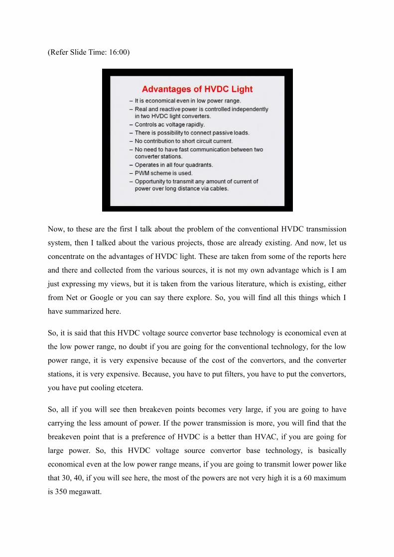
Now, to these are the first I talk about the problem of the conventional HVDC transmission
system, then I talked about the various projects, those are already existing. And now, let us
concentrate on the advantages of HVDC light. These are taken from some of the reports here
and there and collected from the various sources, it is not my own advantage which is I am
just expressing my views, but it is taken from the various literature, which is existing, either
from Net or Google or you can say there explore. So, you will find all this things which I
have summarized here.
So, it is said that this HVDC voltage source convertor base technology is economical even at
the low power range, no doubt if you are going for the conventional technology, for the low
power range, it is very expensive because of the cost of the convertors, and the converter
stations, it is very expensive. Because, you have to put filters, you have to put the convertors,
you have put cooling etcetera.
So, all if you will see then breakeven points becomes very large, if you are going to have
carrying the less amount of power. If the power transmission is more, you will find that the
breakeven point that is a preference of HVDC is a better than HVAC, if you are going for
large power. So, this HVDC voltage source convertor base technology, is basically
economical even at the low power range means, if you are going to transmit lower power like
that 30, 40, if you will see here, the most of the powers are not very high it is a 60 maximum
is 350 megawatt.

But, if you see the conventional power HVDC transmission system, they are carrying more
than 1000 megawatt more carry more than 2000, 3000 megawatt power, so it is very very
high. So, this is even though economical for the low power range as well, another major
advantage of HVDC voltage source convertor technology, is that we can control real and
reactive power independently, in the two HVDC light convertors.
So, here if you see the control philosophy, that we were using in the conventional HVDC
transmission system; it is basically we were controlling the voltage and the current, and then
thereby power. One is controlling this current, another is controlling the voltage and we were
maintaining.
So, it was not possible to control the power DC power, we are controlling the real power it
was we were controlling, but we were unable to control the reactive power independently, no
doubt, once your firing is changing, your reactive power is also going to change. So, you are
doing, but still, is not independent control based on the power.
But, here in this technology, we can control both active that is real power and also the
reactive power that is the q power is control independently in the two HVDC voltage source
convertors. And that is a great advantage here, the power are independently means you can
control the DC power, you can control the reactive power, that we need and that is a, that is a
beauty of this HVDC voltage source converter based technology.
Another advantage it is stated, that this HVDC voltage source convertors, can control the AC
voltage rapidly compare to your conventional HVDC transmission system. The reason is that.
The convertor which we use in the conventional HVDC transmission system, they are the line
commutated and there are lot of slowness, in that one. And sometimes they say, it is a
controls much faster even the 20 times faster than, your the conventional HVDC transmission
system. So, it controls the AC voltage rapidly compared to your the conventional
conventional HVDC transmission system.
Another the major advantage is that with the help of HVDC voltage source convertor, we can
possibly connect the passive loads, as I said it was not possible to connect the passive load, in
this conventional HVDC, because we have to control the current one way in one convertor,
and other there. So, what is happening here in the passive load, I mean that you can have the
one convertor, you can directly connect the load and then you can utilize and you can see the
power control and the reactive power, which is not possible. So, here this since we do not

require big communication channel between the two convertors with this technology, we can
control independently. We can control the real and reactive power independently; thereby we
can also control the passive loads independently without any problem. Another here,
advantage although this is also an advantage of conventional HVDC transmission system,
that the no contribution to the short circuit current, whenever there is a fault normally you
know the circuit breakers, there is a bus you are having, so many AC lines.
If the fault is there at that bus, now we calculate and we will see how much the fault is
contributed by this lines, if your HVDC line is there and you can control very fast, then we
can say the fault level contribution by that line is almost nil.
(Refer Slide Time: 21:05)
No doubt in the HVDC line, what is the fault level this I will explain here, suppose you are
having here a bus where so many, so many this your lines are AC lines are there, and if you
are having a DC here conventional I am talking here, the conventional your converter station,
and then you are having.
So, whenever there is a fault here, three phase fault, now we can see the contribution of fault
current from this line, this line and if other lines are there, and what will be the contribution
was from this HVDC link, if this is a slow, so during that fault, during the few cycles, few
mill seconds this will be also contributing the fault current.
But, if can control very effectively, very fast we can say the fault contribution here can we

can make it zero, and sometimes we can take in other way; we can stabilize a system by
controlling this one. So, that is why here this advantage is mentioned that no contribution to
the short circuited current, because we can control very fast. So, that is line is almost we can
we can assume that, it is not going to contribute the fault level at that bus. So, whenever you
are adding the transmission line the fault level at that bus is going to increase as you know,
the impedance seen up for this fault.
If you are adding another line here, the fault will be going to increase, because all this lines
going to be parallel of this. So, that is why we require that designing the circuit breaker
etcetera, that what should be the circuit breaker reading etcetera, that is use to for that is a
found that is a calculated based on the fault level of that bus and contributed by the various
lines.
Another advantage is that the no need of the fast communication between the two convertor
station, as I said we can control these two convertor stations independently; even though
there is only one convertor station, if you are connecting a convertor station with the passive
loads, its only one convertor station. So, here the communication between these two, suppose
you are having two bilateral here, that one is the rectifier another is inverter.
So, this is a fast communication is not required between these two channels, they can work
independently and that is the beauty of this HVDC voltage source convertors. Another here
advantage is that, HVDC transmission system based on the voltage source convertor
technology, can operate in all the four coordinates of your operation means, if you are having
here, you can see this is the four coordinates, and if you see our conventional thyristor
HVDC transmission system.
We had, if it is your I, this is your voltage we find that we can have the operation is this 2,
here this is your rectifier mode. And if you are going this side, then it is a inverter mode,
because the power voltage is reverse, the power is you know the power is just technology, p
is your v into I P=VI p voltage at the reverse, then you are going in the inverter mode
(Refer Slide Time: 23:25). But, with the help of this, we can even though operate in this
coordinate, at this coordinate as well, having the voltage on the y axis and this is your current
is x axis.
So, we can operate this, because we have the full freedom into control and then, we can
operate in all the four coordinates that is the beauty of this and wherever you want, you can
control here and there. So, this that is why it is said, this can operate in the all four
coordinates of the V I plane. Another why basically, why it is a possible to use, that we can
use the pulse width modulating, its PWM scheme, that can be used and you know the if we
are using the pulse width modulate scheme, you can a achieve a lot of advantage.
Those where the problem in the conventional HVDC, because there is the harmonics and
other things, we can minimize the harmonics, we can minimize the reactive power demand,
we can fire in a such way using the pulse width modulated control, there is a various type of
the pulse width modulated schemes are there, that can be used here and based on that, we can
solve the various problems, those where in the conventional HVDC transmission systems.
So, using the pulse width, we can improve the power factor, we can improve the harmonics
injection means, there is we know in minimum harmonic injection in the system, and also we
can operate very effectively in all the four coordinates of V I plane. Another thus advantage
that opportunity to transmit, any amount of current of power over the long distance via cable,
here the opportunity to transmit any amount of current of current of power over the long
distance, I mean to see that, it is also in HVDC that we can load the system up to its thermal
limit.
What ever the current is that, is a is the thermal limit is there, we can go up to that limit and
we can load and in this cable because, the DC cables are going to be more more popular,
because the AC cable you know the charging is a big concern, and you cannot load even up to
their thermal limit, because the charging is a huge requirement. But, if you can go here, then
you can use this HVDC light means, one side you can have a convertor, then you can have a
DC cable and then you can have AC, so it is no limitations and you can go for the longer
distance.
And it is a very small and you can control all the way independently, real and reactive power.
So, this is giving opportunity to transmit the current limit, not is a any amount which we
cannot go after infinite amount, there is a some limitation means, that we can go up to a
thermal limit without making any problem.

(Refer Slide Time: 26:24)
Another people say, now a question is why this HVDC, the ABB has a call it HVDC light,
that it is they say, it is a really light in weight, what is means, it has a low complexity and
why the low complexity, because it requires the fewer components. Because, we do not
require the filters, we require the filters of certain magnitude, because we can minimize the
filters by control itself.
So, the we require the fewer components, so we require the lesser size, lesser speed, lesser
sorry space and thereby, we can say it is a light in the weight, means it is if you will see the
conventional HVDC convertor station is very bulky you require a big room for your
converter station. Then you require the cooling, then you require the filters all the things we
are keep on adding is a very bigger station, but with the help of this voltage source convertor,
we can minimize, so many things.
And you know the size of reactors are nothing but, they are size of transformers, we require a
smoothing reactors, we require the various filters, and if you will see the inductors and other
values are used, you see for the even though higher the lower order frequency 5th and 7th you
see find there reactors just like a transformers.
So, and next here, I can say this complexity is low and I can say thanks to fewer components
those are used, also we do not use the line commutate circuits for commutation of the
thyristors, we can simply turn it off and turn it on, whenever we require. But, however in the
conventional grid, if HVDC technology if we are using thyristors, then you require some

extra circuit, to turn it off the thyristors while they are conducting; also I said they are small
small in the sense, the small space is required, they are very compact and that is why it is
called HVDC light. Another advantage that you know that is, now the windmills or the wind
farms, whatever you are calling, now people are putting all this wind farms not only on the
onshore, but they are also offshore.
And they are also putting in the sea, because most of the European seas, they are the shallow
and the most of the farms are in the sea and by the way we have to collect the power from
them. So, then if you are using your AC cables, now the question is which type of wind farm
you are using, you are using the doubly fed induction generator or you are using your
induction just simple squirrel cage induction generators or you are using the permanent
magnet synchronous generators. All this here the technologies are existing, but we have to
most commonly used the doubly fed induction generator for the larger capacity.
So, if you are using the induction doubly fed induction generator DFIG we call it, then the
power which you are putting connecting to the system, it is AC power. So, once you are
having the AC power, and then you are using the long AC cable may be of 70, 80 or 100 kilo
meters, then the charging and other problems is the big concern. So, what we can use, we can
use the DC cables, we can use the converter station very near to in the very near to the in the
collector of the wind farm.
If you are using the conventional, then it becomes a very bulky as I said, you require huge
space and in the sea putting all this is very very expensive, but now since having the fewer
components, the smaller compact, we can put the HVDC voltage source convertor near to the
collector system of the wind farms or windmills. And then we can have the DC cable and
finally, we can take it to the shore and finally we can again transmit, in terms of or we can
convert from DC to AC and finally, we can connect with the grid or distribution or
transmission whatever the grid you want to connect.
So, it is very useful for the wind mills, and we will see some of the application in our
previous in the next lectures, this I will discuss about. Another advantage that it can offer
asynchronous operation, this is true and this is equally valid for all the applications, even
though even though conventional HVDC transmission system, can also can also connect the
two asynchronous means the two different frequency systems can be connected by the DC
links, that is no doubt. But, this offers more advantage that it can be very fast control, very

better one in the various way we can control real and reactive power as well. So, this offers
the more advantageous in asynchronous operation compared to the conventional HVDC
transmission system. So, with this advantage I can say it offers a lot of advantage, and but
still we can see the IGBTs base technology is still, it is not so cheap compared to our
conventional HVDC technology. Because, here the IGBTs are still expensive compared to the
thyristors.
So, the whole convertor is still you can see just in this example as I saw, here the ratings are
still not very high compared to your thyristor technology. But, again we can thanks to the
power electronics development, and we can say in the future there will be surprises, we can
go for the all these things, we can go for the more than 1000 megawatt power over this higher
voltage may be plus minus 500 ±500 kV , approximately 800. Once this IGBT technology
will be more mature we will have, when the lesser cost higher rating development etcetera
will take place, and then we can go for this more and more.
So, that is why this HVDC voltage source convertors, now there is ABB, siemens all other
manufacturing companies, now there is doing lot of research, lot of other development is
happening in this area. So, that in the future, we will find this HVDC that is the base standard
voltage source convertor, will be more useful compared to the current source convertors, so
these are the advantage we saw.
(Refer Slide Time: 31:52)
Now, we have to go for CC HVDC light technology, HVDC plus here basically, the HVDC
light is a high voltage, direct current transmission technology, and the transmission up to this
330 megawatt and for the DC range the 150 voltage. So, we saw with the various application
here, even though we saw some times some short term ratings is 350 megawatt, and but the
voltage level is right now is only limited 150 kilo volt. But, again some of the going to be
synchronized with maybe even though not I have notice, but may be the voltage rating is
more than this 1 plus minus 150 kilo volt ±150 kV range.
But, I am sure in the future, we are going to get higher voltage level and higher power
transmission via, the voltage source convertor HVDC system. So, here in this, it consists of
again two AC to DC convertors stations and appear of underground cable in the connecting
each convertor stations means, what here we are getting that is the similar to that here, we are
having this is a one station and that is we require two cables, if you are using two bipolar and
here you are having another sorry another convertor here, that is the inverter here (Refer Slide
Time: 32:51).
I can say and here you are having the rectifier and if you are having the bipolar operation
then, it is a grounded and then you are having another one here, and then you can operate
here with this this is a grounded and then I can say this is your. So, this is your operating
positive, this is negative and then it is a bipolar operation that we are having. So, this
technology provides the HVDC light convertors with the switching speed 27 times faster than
the traditional HVDC thyristor control convertor, comparing the thyristor based HVDC
transmission system we are converter technology, which is used in the transmission system, it
is more than 27 times faster.
So, that it is almost very fast and then we can, that is why we can achieve whatever the
advantage, whatever the problems were there that we can overcome and we can get the
advantage by this voltage source convertor based HVDC transmission system and
technology.

(Refer Slide Time: 33:55)
Now, we will go for this principle of HVDC light, so the principle of HVDC light that can be
understood by this diagram, you can say the HVDC voltage source convertor is basically
composed of whole transmission system. Basically, I am talking is composed of transformer,
you can see this is a transformer, this is a convertor transformer we call it that is connecting
your AC system, then with the your convertor system, we are having the filters, we also need
the filters.
As I said in the beginning, that is not that even, we using the here the thyristor are even as
IGBTs it is a free from harmonics, some harmonics are injected. So, we require some of the
filters, may be it is again the band pass filters etcetera that we can use the some filters, and
filters are used. And then we require, the DC capacitors that is more important, we use the
here the convertors, you can say this is a convertors here, we use the reactors here and we
also use the capacitor.
One big difference you will find from your HVDC conventional, HVDC transmission system,
that earlier we were using this, we were using the transformer, we were using this filter, we
were using this convertor,no doubt those convertors were based on the thyristor, based or the
GTO base technology. But, we were using here the reactors, especially to smoothen, the
ripples of the DC as well as to have the constant DC current, we are using the inductors that
were the series of this convertor.
But, instead of that we are using the capacitors and that is called the DC capacitors and they

are use in this way, and there are basically putting here the voltage constant. So, that is why it
is the voltage source convertor, and it is not a current source; if you are using current source,
you have to use the current constant and is a ripple free and then for that you have to use the
your smoothing reactors. So, the transformer is used to step down the AC voltage to satisfy
the demand of commutated commutative solid state devices and self commutate, they are not
line commutated.
So, they are self commutate and such are the series and the parallel combination of GTOs,
IGBTs are the IGCTs now the again people are talking the insulated gate control thyristors,
that can be also used. Here, the transformer here we are using, if you are taking this is a
convertor you can say from AC to DC, here means your AC voltage is higher and your DC
voltage is lower because, the again due to the limitations on the converter side, the voltage is
again as say that we are going up to only plus minus 150 kilo volt.
And this side we can have even though 760 kilo volt or may be AC side we can have the 1100
kilo volt, so this transformer is basically nothing. But, the step down transformer, if you will
see from here this is your primary, always you know the step up and step down transformers
are designated and this classification is only valid, if they are connected in this system. So,
which is your primary source, which is your secondary, when it is connected when you can
call it step down?
So, if your power is flowing from the high voltage to low voltage, then we can say this step
down transformer. So, this is the step down transformer from high voltage AC to DC and then
this side the lower voltage, and then we are rectifying here and that the DC voltage is coming
here. So, this is a step down, same way this is a rectifier operation, because from AC to DC.
But, if you are using the same here concept that power is flowing from this side to this side.
So, this because this becomes your inverter, and this inverters you can say this lower voltage
DC, now it is coming all the way here, we are going to step up, because the this both side the
voltage is lesser than compared to this side. So, this power is flowing from this side to this
side, then this transformer is just as a step up transformer and here this is used to the self
commutate side, the solid state device, because we are having the limited the voltage rating
and another things, and that is why, we it is used.

(Refer Slide Time: 37:40)
Now, the high frequency components caused by this switching or switches or valves are
isolated from the power system by the filters, the filters are used that whenever the high
because, the switching is very fast, and the switching harmonics those are going to enter in
the system, they are used by this filters basically. So, whenever the switching harmonics are
there, they are coming here in the AC system that must be filtered out here, and that is why
the filters are used, so we can filter out the high frequency.
So, we can pass the high frequency, and put it to ground and only we can pass the
fundamental or nominal frequency power in that side. So, the key part of this HVDC light or
the convertor, which can be realize by the conversion of AC to DC by directly. So, it is
always from AC to DC or DC to AC that can be utilized and it is very fast control, that is a
possible.
Another difference as I said, thus we are having here the DC capacitors, in this HVDC
voltage source convertor and you know the voltage source convertor, means you are
connecting the DC with the capacitor. If you are using your inductor, means it is a current
source convertor it is very well and general, it is very you know vague differentiation,
although people would defining this voltage source, and the current source convertor in
different way.
So, the DC capacitors are used as the DC voltage source, because here the charging and the
discharging is done by the DC capacitors. In this this system which need being charged and

the recharged recharge, because your charging and recharging, whatever the power which is
flowing, this basically the capacitor here, works as a shock absorber; means whenever the
power is going from here. And it is not transmitted completely to another end, this capacitor
gets charged, means store that energy and the voltage rise and then whenever, it is require
suppose you are putting less energy and more energy is withdrawn, then this capacitor is
discharged.
So, charging and discharging are done here the capacitors are used for this to the always
charge and discharge and we require a big DC DC capacitors, and that is a major difference.
However, in the conventional we are using inductors, inductors were also storing the energy,
whenever the currents is changing with the frequency of the current were changing, so half I
square 12
LI 2 you know the current is there, so energy is stored but, that is a current based.
Now, to see this whole here the philosophy, which I said here suppose this is a one side, you
are having another side, so that can be here seen by the equivalent circuit, you can see how
we are going.
(Refer Slide Time: 40:05)
So, this is you can see, this is the current which is flowing from here, we are having this is
this inverter operation, we are having single phase is represented by you can say I d is
flowing and thus we are having our I g, it is here based technology. And this is the voltage
that is from 0 to this U d and I can say, this is your inductor which is connected and the

current is flowing, and this is going this side. So, we can write, what will be the power, that is
a here the magnitude and the phase angle decide the reactive power and active power
exchange between the AC to DC system, here the DC this side this is AC. And believing this
power is flowing from the DC to AC side.
Similarly, the same concept can be utilized from the AC to DC system as well, the power
transmitted by the DC light is given by, how much power this we are showing from here, that
will be basically the voltage here, this is a side we are having the AC. So, this apparent power
that is complex power here, S b if taking the mod it is apparent power, but this S b is the
complex power, that is the you are having real and reactive component, there is a real
component is P. And your reactive component is Q that can be written, no doubt here since,
we are having the single phase.
So, it is a three phase multiplied by the phase voltage U and multiplied by I R the current
which is flowing here. So, this you can say V I conjugate it is a very well formula you know,
under root three term is appearing, because the voltage here we are taking the single phase,
the phase voltage. Because, if a 3 phase system, so it is a thats under root 3 multiplied by
here, the line to line and this is a current, so we have this U F we are taking line to line, so
this a 3 phase power. So, whatever the DC power it is going it is going to be the 3 phase AC
power.
So, this always, if as we assume the converter is loss less, then we can say the DC power real
power will be equal to your AC real power. So, this under root 3 basically term is appearing,
because this U F we are taking line to line, if we are taking this phase then this will be 3. So,
this under root 3 term is appearing, you know it is a very very basic concept of electrical
engineering, and this is I conjugate and thus I conjugate, we can write what is I R here, it is a
the voltage this minus this because, we have taken this direction.
So, this U C minus U F and then here sorry we have left this conjugative you can make here
conjugate. So, this is we are putting divided by your the Z R and Z R is nothing but, this is
what is the impedance between this your U C and U F. So, you will see that terminology
which are use, S b this is the magnitude here, it is a is apparent power of HVDC light, P is the
active power, Q is reactive power, U F is the voltage of AC system as I said is AC system side
here, U C is the output voltage of the converter which is coming here, and Z R is clearly you
can see here is the equivalent impedance of the converter system, including the transformer
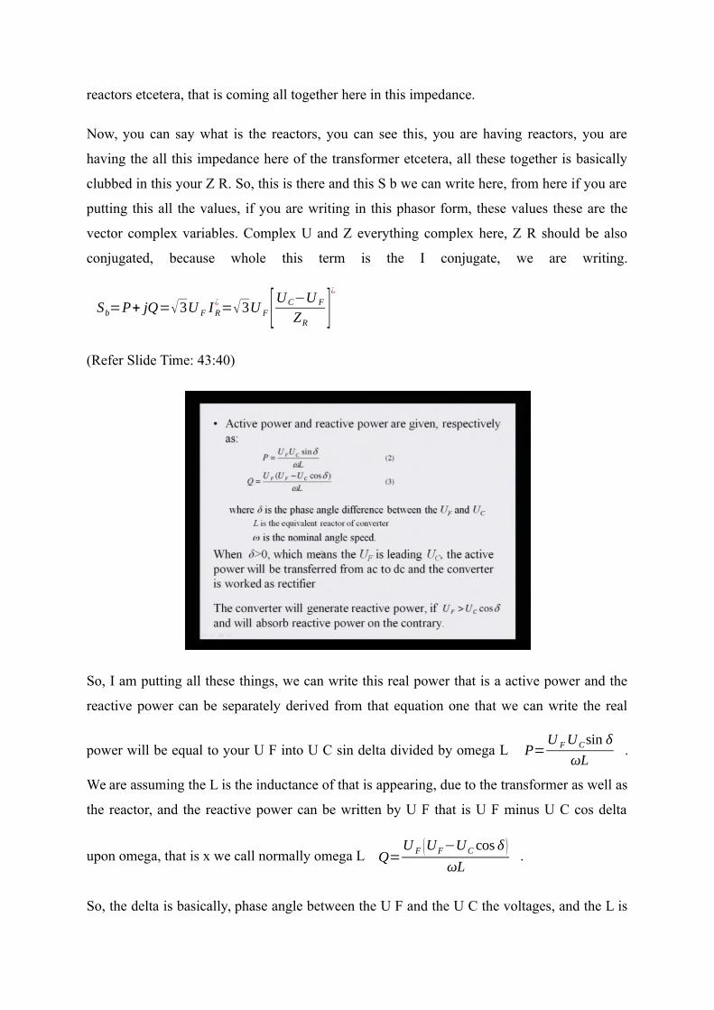
reactors etcetera, that is coming all together here in this impedance.
Now, you can say what is the reactors, you can see this, you are having reactors, you are
having the all this impedance here of the transformer etcetera, all these together is basically
clubbed in this your Z R. So, this is there and this S b we can write here, from here if you are
putting this all the values, if you are writing in this phasor form, these values these are the
vector complex variables. Complex U and Z everything complex here, Z R should be also
conjugated, because whole this term is the I conjugate, we are writing.
Sb=P+ jQ=√3U F IR¿=√3U F [UC−U F
ZR]¿
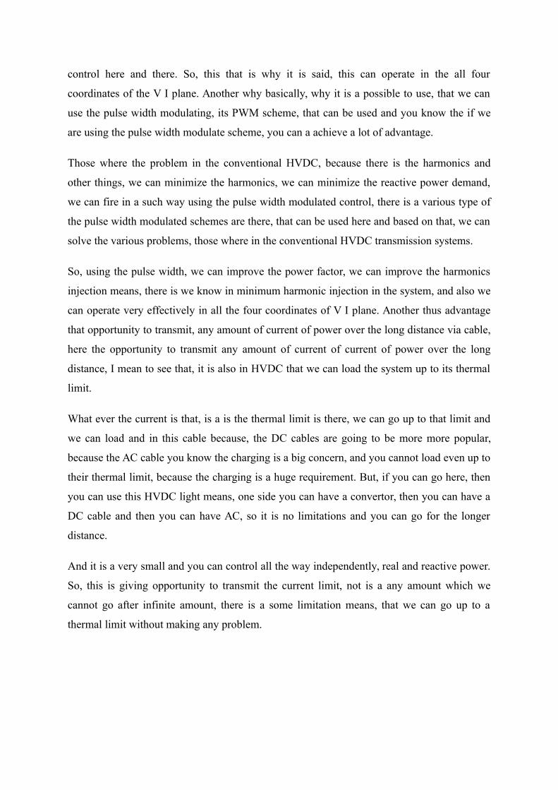
(Refer Slide Time: 43:40)
So, I am putting all these things, we can write this real power that is a active power and the
reactive power can be separately derived from that equation one that we can write the real
power will be equal to your U F into U C sin delta divided by omega L P=U FUCsin δ
ωL.
We are assuming the L is the inductance of that is appearing, due to the transformer as well as
the reactor, and the reactive power can be written by U F that is U F minus U C cos delta
upon omega, that is x we call normally omega L Q=U F (UF−UC cos δ )
ωL.
So, the delta is basically, phase angle between the U F and the U C the voltages, and the L is

the equivalent reactors converter of the equivalent reactance of the converter along with the
transformer etcetera, and omega is the nominal nominal this is speed, that is radian per
second, this omega is a frequency of the system, that is a 2 pi F 2πf , you know it very
well and F is a frequency of the system. When alpha is greater than 0 means, alpha positive,
means this P it becomes the positive, which is flowing from your going to the AC system.
And since, that is you can see this U F is the leading U C, and the active power will be the
transferred from the AC system to DC system, and the converter it is work to rectifier.
Now, if you are taking that is another here in this derivation, I took for the inverter system,
but we can equally write the equation for the rectifier system, and based on this delta, we can
say whether it is going into this rectifier system or it is coming out from the rectifier system,
it decided by the delta, what is you have taken the is U F delta a U C delta, all these things
you can very clearly, you can define and you can find the power is going here.
One thing you can find here, this reactive power the reactive power here, we are having the U
F and U C and your delta. So, this reactive power that you can control as I said it is a very
control variable, we can independently this and this we can control, because here you can
control the U C. And thus converter will generate reactive power, if this value is positive
which U F is more than U C cos delta, then this value is positive, means it is generating
reactive power in the rectifier side; and it is again the reverse is also true and it will be
absorbing the reactive power on the contrary if it is a reverse only that.
So, you can see this real and reactive power, they can be control independently, we can
control the delta here one side, we can control the U C and by these, we can control the p and
your real and reactive power independently. So, in this and the remaining things we will
discuss in this our next lecture, now here I want to summarize that, in this lecture what we did
we basically saw, the various problems of conventional HVDC transmission system. Already
I just discuss, it very detail although, the same thing was also discussed in the very first
lectures of the module first.
Where we discussed the various problems compare that time I compared your AC system and
the DC system, in this one I had compare the HVDC voltage source converter, and the
HVDC current source converter, current source converter based HVDC transmission system;
means you have thus we call the conventional system. And whenever we are talking this
voltage source converter based HVDC system, this is HVDC light or HVDC plus, we also

saw the various components, then we saw the what will be the real and reactive power, how it
is a flowing and how it is going, and that is also derived in this this lecture.
In this next lecture, we will see the various control philosophy, we will see the various cable
approaches and also I will talk about the hybrid transmission system having the HVDC light,
already having in the AC and DC system; means if you are having already DC conventional
DC system, if you are putting this HVDC with the voltages source converters, what will be
the advantage, what will be the what will be the various impact basically, we will discuss in
the next lecture.
Also we will find that is the multi in feed HVDC system, because you are having the multi
terminal systems, where you are having the, and then you are having HVDC light, and then
what will be the various gain, we can have that will be discuss in our next lecture, thank you.
Keywords: HVDC light, HVDC plus, constant ignition angle control, constant extinction
angle control, current source convertors, classical HDVC technology, reactive power support,
Pulse Width Modulation (PWM), Doubly Fed Induction Generator (DFIG).