high temperature testing of ceramicskutik.bzlogi.hu/fileadmin/uploads/prezentaciok/prez... ·...
TRANSCRIPT

HIGH TEMPERATURE TESTING OF CERAMICS
František Lofaj
Institute of Materials Research of SASKošice, Slovakia
Carpathian Virtual Institute for Research and Innovation
Summer School
August 28, 2007

OutlineIntroduction•
Advanced ceramics vs. advanced structural ceramics
•
Market with the advanced ceramics –
an overview•
Applications of advanced ceramics
•
Requirements to HT structural ceramics in CGTTesting at HT – mechanical tests
Geometry (bending, compression, tension)Strength, fracture toughness, creepTensile creep testing Creep mechanisms – techniques of theirdeterminationCorrosion resistance
•
Conclusions

ADVANCED CERAMICS VS. ADVANCED STRUCTURAL CERAMICS
•
Traditional ceramics-
building (bricks, concrete, glass..).
-
pottery & home tools-
refractories
(blast furnaces, etc...)
•
Advanced ceramics -
electronic (wafers, chips, etc...)
-
structural ceramics (for heat-, wear-
and corrosion-
resistant components
-
others (e.g., coatings, bioceramics... )

OLDER & NEW “TRADITIONAL” CERAMICS

Market in Advanced Structural Ceramics in North America by Industry, 2005 and 2010
($ Millions)
Source: BCC Research, 2006

Summary of the advanced ceramic market in US
•
The North American advanced structural ceramic market in 2005 ~ $2.3 billion (65%)($3 bill. by 2010)
•
Its average annual growth rate (AAGR) of 5.8%
•
Bioceramics (2005) ~ $1.5 billion, AAGR of 4.6%. •
Wear-resistant and cutting tool inserts ~ 17% of the total market.
•
Ceramic armors represent about 13% of the total market.
•Energy cost escalations, => more use as components
for heat exchangers, recuperators and as solid oxide fuel cell elements.
Source: BCC Research, 2006

APPLICATIONS OF ADVANCED STRUCTURAL CERAMICS AND CERAMIC
MATRIX COMPOSITES
CUTTING TOOLS BEARINGS PARTS OF ENGINE/TURBINE
AUTOMOTIVE/ AIRCRAFT COMPONENTS WEAR AND
HEAT RESISTANT COMPONENTS
BIOCERAMICS GLASSES...
PIEZO/ELECTROCERAMICS

CUTTING INSERTS AND BEARINGS
60% lighter as steel =>less energy and 80% higher speed silicon nitride
High hardness and wear resistance –
silicon nitride,
alumina, sialon
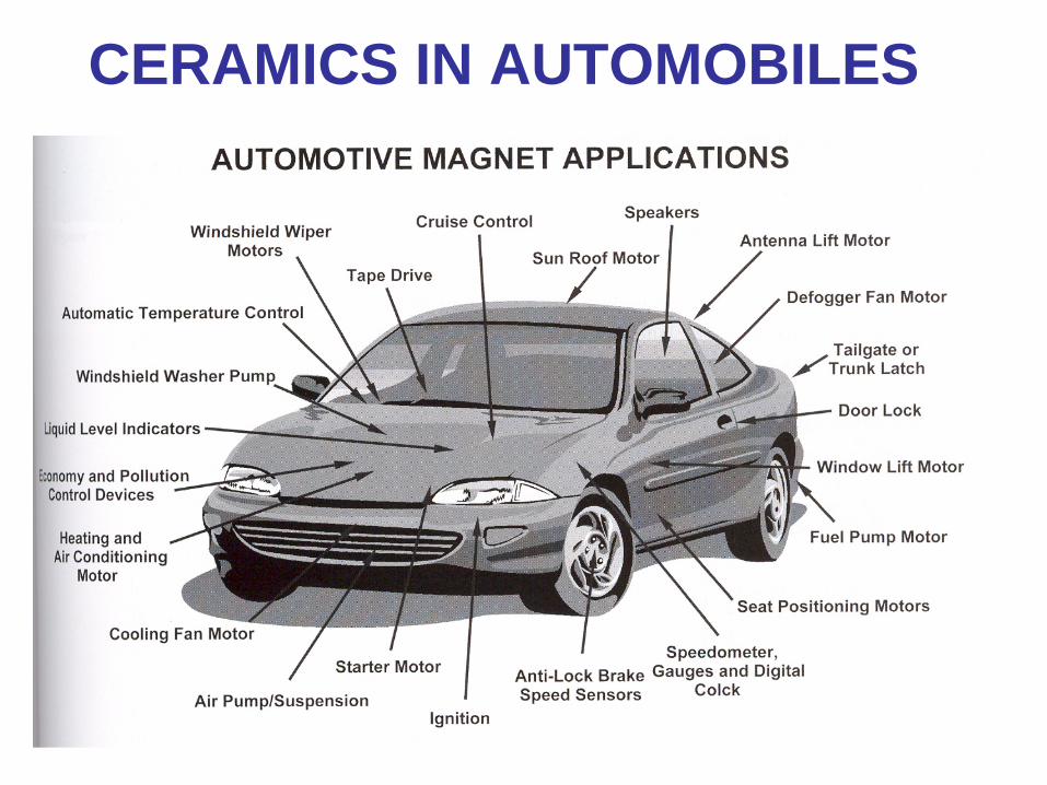
CERAMICS IN AUTOMOBILES

STRUCTURAL CERAMICS IN
AUTOMOBILESOxygen sensor
Water pump seals
Turbocharger
Alumina, zirconia, silicon nitride, silicon carbide
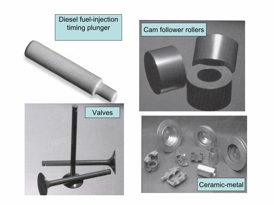
Diesel fuel-injectiontiming plunger Cam follower rollers
Valves
Ceramic-metal

HEAT RESISTANT TILES
33000 ceramic (C-C composite with SiC and SiO2 overcoats) tiles ; TMAX
~1260 C

AIRFRAME COMPONENTS Eurofighter Typhoon.
airframe surface: 70% -
CFCs
15% Al-
and Ti- alloys
12% Glass Reinforced Plastics (GRP)
15% metals 3% other materials
www.eurofighter.com/et_mp_ma_cf.asp

AIRFRAME COMPONENTS Airbus A380
25
wt. % -
Composite materials
Carbon-fibre reinforced plastic, glass- fibre reinforced plastic,
and quartz-fibre reinforced plastic
(wings,
fuselage sections, tail surfaces, doors)
Thermoplastics
(
leading edges). GLARE
(Glass-reinforced fibre Al
laminate) (
upper fuselage
and on the stabilizers' leading edges).
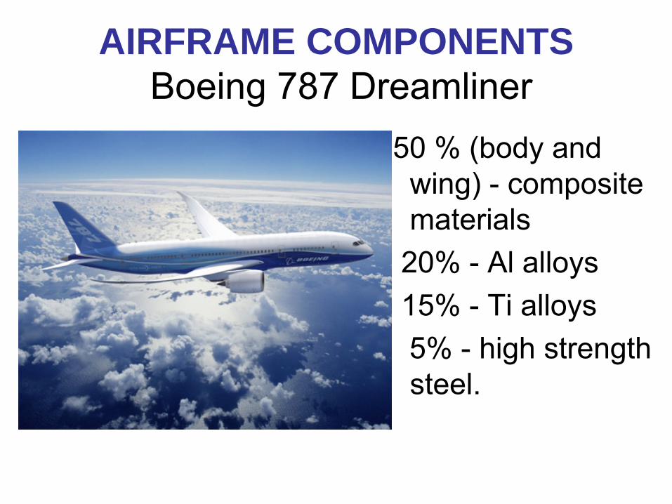
AIRFRAME COMPONENTS Boeing 787 Dreamliner
50 %
(body
and wing)
-
composite
materials20% -
Al alloys
15% -
Ti alloys 5% -
high strength
steel.

EFFICIENCY vs. GT SIZE
Source: http://www.khi.co.jp/gasturbine/english/rd_e/rd1.html]

WHY CERAMICS IN GAS TURBINES ???
Carnot cycle
pressure
volume
Thermal efficiency = (Th
– Tc)
/Th
Tcooler
Theater1
Theater2
Higher operating temperature necessary!!!
Basic thermodynamics of gasses ...

BETTER GAS TURBINES.....
HOT ZONE –
HIGHER TURBINE INLET TEMPERATURE (TIT)

IR Power Works Frame 3

U.S. CERAMIC GAS TURBINE PROGRAMS - History
Brittle Material Design –HTT/ Ford Motor Co. (1971-78)
AGT –
Allison vs. Garrett Co. /AGT 100 vs. AGT 101
(1979-87) 85 h at 1204oC
ATTAP -
Allied Signal -
331 APU (commercially used in the MD 80 and A320 aircrafts since late 90-s)
-
Hybrid Vehicle Turbine Engine Technology -1992
-
Allison AGT 5 engine (5000 h at <1385oC
ATS (1992-2000) -
CSGT (1992-1998)
-
Ceramic Vane Effort
-
Materials and Manufacturing
Distributed Energy -
(2000 -2006) IGT (relatively big -
4-5 MW turbines)-
Microturbines
(relatively small <500 kW turbines)
Subtask: Ceramic Turbine Risk Reduction (Jan 05 –Mar
09)

CERAMIC STATIONARY GAS TURBINE PROGRAM
Solar turbine Centaur with silicon nitride rotor blades, tested
in CA since 1997
4.5 MW turbine for energy cogeneration; retrofit, TIT ~1000 oC; around 50 000 h accumulated; failure due to FOD
Solar Turbine Inc.

DISTRIBUTED ENERGY PROGRAM (DoE)

SILICON NITRIDE COMPONENTS IN MICROTURBINE PROGRAM
PowerWorks 70 kW Source: J.
Kesseli, Ingersoll-Rand Energy Systems

CGT IN JAPAN
Source: www.khi.co.jp/gasturbine
NEDO Program: R&D on CGT (300 kW class)
PEC Program: CGT for automobiles (100 kW)
Thermal efficiency of 42% at 1350 C achieved
Problems with the reliability and lifetime

Development of ceramic turbine components -1981Turbine wheel (ASEA CERAMA)
tested in a car 1982
GT110 demonstrated reliable at 1250 ºC -
1987
European AGATA project developedCeramic radial turbineCeramic recuperatorCeramic catalytic combustor
Source: Lars Sundin, Volvo Aero Presentation,
July
2003,
Brussels
KTT MK II / GT110•Developed 1985- 1987•Automotive GT for cars.•Power 115
kW (155 hp)•2-shaft with ceramic HP turbine•Low emission combustor (LPP)•
EUROPE and CGT (SWEDEN)

CGT – success or failure???Silicon Nitride ceramic rotor technology is
adaptable at moderate temperatures
and stresses(up to 20,000 /mo turbine rotors were produced (2003) for the turbocharger industry)
Main benefits: •
Increase in thermal efficiency (C200/ORC system -
38% electrical
efficiency (Mar 2005))•
Slightly better fuel economy (7%)
•
Higher output power•
Significant NOx
reduction
Main problems:�•
Water vapor corrosion at higher temperatures
•
Long term reliability•
FOD
•
Component price

CRITICAL CERAMIC COMPONENTS
Vane ring stator nozzles
Radial Turbine Wheels
Rotor blades/blisk
Combustor (SiC, C-C)
Recuperator
SILICON NITRIDE – Si3 N4
Static load100 000 rpm at >1000 -1400 C

Requirements to structural ceramics in CGT
TIT > 1300oC
[ Licht]:•
Flexural strength at RT and at 1300oC -
>950 MPa and > 600 MPa, respectively;•
Weibull
modulus >12
•
Fracture toughness > 6.5 MPa. m1/2
•
Creep rate < 2 . 10-8 s-1
at 1250oC and 130 MPa.
•
Oxidation and corrosion resistance up to 1250oC

MODES OF MECHANICAL TESTING
Tension
Strain = relative size (length) change
Compression Bending

What is STRENGTH?
strain
4-point bendingStress
Strain
Brittle behavior
Ductile behavior
Strength
> 10 samples ( tests) to get the strength... at each temperature
Slope = Young’s modulus

STRENGTH and FAILURE
Tension - the largest flaw propagates (after reaching critical stress)
Compression - many flaws propagate => general crushing

STRENGTH
σ = KIC /(πa)1/2
High strength ceramics require:
•small defects (ceramics - several um, in metals – tens of mm)
•higher fracture toughness (in ceramics <10 MPa.m1/2, metals - >50 MPa.m1/2)
KIc
–
fracture toughness; a –
flaw size

STRENGTH STATISTICS
Chalk - Pf = 0,3
cutting tool - Pf = 10-2
protective tile of space shuttle - 10-8
Strength of metals = deterministic
strength of ceramics = probabilistic

FAILURE PROBABILITY IN BRITTLE MATERIALS
VOLUME DEPENDENCE OF STRENGTH
Large sample fails at a lower stresses

Weibull: survival probability Ps (V0 ) = fraction of identical samples with the volume V0 ,
which survive loading to a tensile stress of σ.
Ps (V0 ) = exp{-(σ/σ0 )m},σ0 is the characteristic stress that allows 37% of the samples to survive;
m - Weibull modulus shows the variability (scatter) of the strength.
WEIBULL STATISTICS FOR BRITTLE FRACTURE
Failu
re p
roba
bilit
y

COMPARISON OF FAILURE PROBABILITIES
Higher m : -
technology defect elimination
-
materials with higher fracture toughness
Careful design –
no stress concentration

FRACTURE TOUGHNESS
KI = Y.σ.√a [MPa.m1/2]
KI – fracture toughness (stress intensity factor)σ
- outer fibre bending stressY= Y(a/W) - geometry function
Definition
Pre-defined defect –
crack is necessary

FRACTURE TOUGHNESS MEASUREMENT METHODS
SENB, SEPB, SEVNB, IF, DT ...Chevron
Notch
Vickers indentation on tensile surface

INDENTATION FRACTURE TOUGHNESS
Specimen with Vickers (Berkovich, Knoop) Indentation Crack
KIC ~ H(a)1/2(E/H)1/2(c/a)-3/2

STRENGTH vs. TEMPERATURE and TIME
1300 CRT Temperature
Ben
ding
Stre
ss
Weibull
strength scatter
0.8 –
1.5 GPa
1000 -1100 C
Source: G.D. Queen, 1990
Fast fracture
No failureSCG
Creep fracture
0.001 h
10000 h
Possible failure modes:
1. Fast failure
2.
Slow crack growth
3.
Creep fracture
0.1 h
10 h

What is CREEP?
~ creep
strain
4-point bending creep Creep is time dependent plastic deformation
CREEPBendingTensionCompression

TENSILE CREEP TESTING
+ geometry unbiased values
-
experimentally troublesome: serious alignment problemsdifficult elongation measurement
-
expensive
Hot grips vs. Cold grips

Creep behavior of SN 88 silicon nitride (Yb/Y-based additives)
0
0.005
0.01
0.015
0.02
0.025
0.03
0 20 40 60 80 100
Tens
ile S
train
Time, [h]
1400°C/ 150 MPainterrupted creep tests
No. 3: 5.70 h, 0.51 %
No. 4: 24.0 h, 1.20%
No. 5: 70.0 h, 2.30 %
No. 6: 85.06 h, 2.70% creep fracture
6
5
4
3
1400oC/ 150 MPa
Minimum strain rate

CREEP RESISTANCE IN COMMERCIAL Si3 N4 CERAMICS
Cree
p Ra
te, s
-1
150 MPa
SN 88
(Yb2 O3 )
Temperature, oC
AS 950
(SiC part.)
Pure SN 75 MPa
NT154 (Y2 O3 ) SN 282SN281
(Lu2 O3 )1% after 10 000 h

CREEP MECHANISMS IN VITREOUS BONDED CERAMICS
Initial state Deformed Creep Mechanisms:
1. Mutual sliding of grains
2. Viscous flow of glassy phase
3. Grain shape change
4. Cavitation„strain“
CAVITATION is crucial for creep behavior of ceramics

CAVITATION – TECHNIQUES OF THEIR
MEASUREMENTDESTRUCTIVE NON-DESTRUCTIVE
Density change Tensile – compressive
A-USAXS strain
TEM/SEM Ultrasonic velocity
SLAM

Densitometry (Sink-Float)
water heater/cooler for temperature control
H2 O
thermocouple
water solution of thalium malonate formate
ρ
~3.55 g/cm3Standard 1
Standard 2
Grip sample
Gauge sample
density of TMF solution linearly changes with temperature
mV

DENSITY CHANGE VS. STRAIN
Δρ/ρο
= (ρgage - ρgrip )/ρgrip = - fv
relative density change = - volume fraction of cavities
0
0.01
0.02
0.03
0.04
0.05
0.06
0 0.01 0.02 0.03 0.04 0.05 0.06Tensile Strain
1.0SN 88 silicon nitride1400°C - 1500°C
fv = 0.85 + bε
slope 0.85
Vol
ume
frac
tion
of c
aviti
es
Cavitation strain
Creep strain

ULTRASOUND VELOCITY MEASUREMENT
Pulser/Receiver
20, 10 MHz Transducer
Δt
d
V l,sh = 2d/Δt l,sh
oscilloscope
50 MHz
measurement locations

Ultrasound velocity vs. Strain
10150
10200
10250
10300
10350
10400
0 0.005 0.01 0.015 0.02 0.025 0.03
specimen A - interrupted test
specimen B - interrupted test
9 interrupted creep tests
Ave
rage
Rat
e of
Lo
ngitu
dina
l Wav
es, [
m/s
]
Tensile Strain
SN88, 1400°C, 150 MPa
ε th <0.001
grips
vl0 = 10390 ± 35 ms-1
gauges

ELASTIC MODULI VS. CAVITATION
-0.08
-0.07
-0.06
-0.05
-0.04
-0.03
-0.02
-0.01
0
0 0.005 0.01 0.015 0.02
(E-E0)/E
0
(G-G0)/G
0
(K-K0)/K
0Rel
ativ
e C
hang
e of
the
Ela
stic
Mod
uli
Volume Fraction of Cavities (= Porosity), fv
SN 88, 1400°C/ 150 MPa
(X - X 0)/X 0 = bx . fv

CAVITATION BY SLAM
A
A – compressive strain zone
B – neutral axis zone
C – tensile strain zone
C
4-point bending creep, experimental silicon nitride
B

CAVITATION BY SLAM
High attenuation zone development in tensile stress zone

OXIDATION RELATED MICROSTRUCTURE CHANGES
ST1 silicon nitride
1400oC, 70 MPa, 270 h, 15.4 % strain
Layer formation during HT
creep in air
1400oC, 50 MPa, 263 h
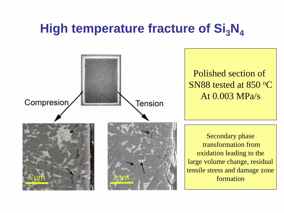
High temperature fracture of Si3 N4
Polished section of SN88 tested at 850 oC
At 0.003 MPa/s
Secondary phasetransformation from
oxidation leading to thelarge volume change, residualtensile stress and damage zone
formation

CONCLUSIONSStructural ceramics reached their maturity and found wide applications at room temperature
High temperature ceramics have limited applications up to now and further development is necessary
Main problems for HT ceramics include water vapor corrosion, long term reliability and cost
Problems with HT testing of ceramics :
Temperatures 1200 –
1600 C
Stresses –
up to 600 MPa in tension/400 MPa for long term tests (up to 100 00 h
Difficulties with the elongation measurement
Role of environment