high strength resilient ce earthbag: strip rc footings for
TRANSCRIPT

HIGH STRENGTH RESILIENT CE EARTHBAG: Strip RC Footings for Moderate to High Risk
March 2021
Patti Stouter
Build Simple Inc., Albuquerque, New Mexico
Figure 1: Best reinforcement for contained earth use in high seismic risk areas.
High-Strength Resilient CE Earthbag by Patti Stouter is licensed under a Creative Commons Attribution-NonCommercial 4.0 International License.
CONTENTS:
PART I: BASIC EARTHBAG INFORMATION
1 INTRODUCTION 4
2 MATERIALS FOR RESILIENT CE 13
3 PROVING SOIL FILL STRENGTH 18
PART II: HIGH STRENGTH RESILIENT CE REINFORCEMENT SYSTEM
4 THE BASICS OF RESILIENT CE FOR MODERATE TO HIGH RISK 22
5 PLANS FOR RESILIENT CE 24
6 FOOTINGS FOR MODERATE TO HIGH RISK 29
7 EMBEDDED REINFORCEMENT FOR MODERATE TO HIGH RISK 33
8 INTERCONNECTED WALLS FOR MODERATE TO HIGH RISK 46
9 WALL OPENINGS FOR MODERATE TO HIGH RISK 52
10 BOND BEAMS FOR MODERATE TO HIGH RISK 55
11 OPTIONAL CONSTRUCTION DETAILS 57
12 ABBREVIATIONS AND DEFINITIONS 63
2Build Simple Inc., March 2021

This document is dedicated to Owen Geiger for taking the time to teach and demonstrate earthbag worldwide. He kept answering question after question that I asked. Owen encouraged natural builders to use earthbag, but also warned that earthquake forces needto be considered carefully.
Kelly and Zana Hart: thank you for encouragement, feedback and suggestions throughout the past ten years.
No engineer has specifically approved the construction detailing contained in this volume. But thanks are due to engineers who have been invaluable in evaluating improved techniques for earthbag, including:
Dilendra Maharjan, Heatly Engineering
Anthony Dente, Verdant Structural Engineers
Tonya Nilsson, Santa Clara University
Brandon Ross, Clemson University
Gabriel Miller, Blue Marlin Residential Engineering
Thanks also to the Creator for giving subsoil the qualities that allow us to create beautiful and safe buildings of earth.
3Build Simple Inc., March 2021
PART I: BASIC EARTHBAG INFORMATION
1 INTRODUCTION
EARTHBAG VS. EARTHQUAKES
Conventional earthen buildings are well suited to areas with minimal or no seismic risk. But where risk is moderate earthquakes often damage or destroy unreinforced buildings ofearth, stone, or brick.
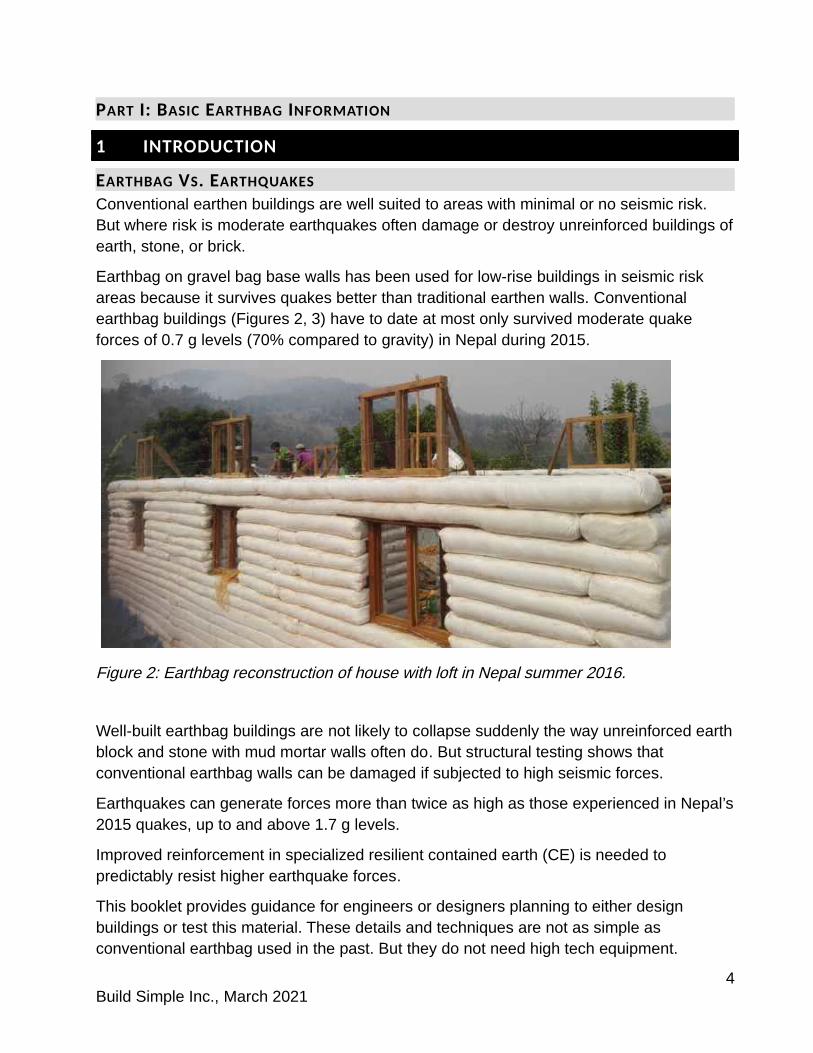
Earthbag on gravel bag base walls has been used for low-rise buildings in seismic risk areas because it survives quakes better than traditional earthen walls. Conventional earthbag buildings (Figures 2, 3) have to date at most only survived moderate quake forces of 0.7 g levels (70% compared to gravity) in Nepal during 2015.
Figure 2: Earthbag reconstruction of house with loft in Nepal summer 2016.
Well-built earthbag buildings are not likely to collapse suddenly the way unreinforced earthblock and stone with mud mortar walls often do. But structural testing shows that conventional earthbag walls can be damaged if subjected to high seismic forces.
Earthquakes can generate forces more than twice as high as those experienced in Nepal’s2015 quakes, up to and above 1.7 g levels.
Improved reinforcement in specialized resilient contained earth (CE) is needed to predictably resist higher earthquake forces.
This booklet provides guidance for engineers or designers planning to either design buildings or test this material. These details and techniques are not as simple as conventional earthbag used in the past. But they do not need high tech equipment.
4Build Simple Inc., March 2021

Figure 3: Plastered School in Phuleli by Edge of Seven and Small World Nepal survived the 2015 earthquakes without damage despite earthbag construction with conventional techniques.
Builders without code restrictions or requirements from investors may not be willing to use these more complex techniques or increase their amount of costly concrete and steel. But some builders and owners will feel that an investment of time and modest increases to material costs are well worth while if they ensure natural buildings can survive.
CONVENTIONAL EARTHBAG CONSTRUCTION
Earthbag building requires a lot of heavy labor but few power tools, few and low-cost manufactured materials. It is an immediate process with few steps of preparation. It is usually lightly reinforced with little advance planning by hammering rebar into walls.
Earthen buildings are more wall than openings, with openings traditionally spaced 0,9 m (36”) away from each other or from wall corners. Walls or buttresses (short stub walls for bracing) are spaced every 3 m (10’).
Gravel-filled bags are often used as a water-resistant base wall and foundation. Earthen courses begin above the finished floor level. Damp soil is poured into fabric bags or tubes used as forms. Bag or tube ends are laid with a running bond type of overlap. Courses conform around shapes beneath, and can be laid over plumbing or electrical elements or support poles. Tubes are closed at the end by tucking under or pinning with wire. Walls are tamped to consolidate and to level courses.
Two strands of barbed wire are laid immediately on each course, 80- 100 mm (3- 4") in from the wall edges (Figure 4a) leaving 180 mm (7”) unobstructed in the center to insert
5Build Simple Inc., March 2021
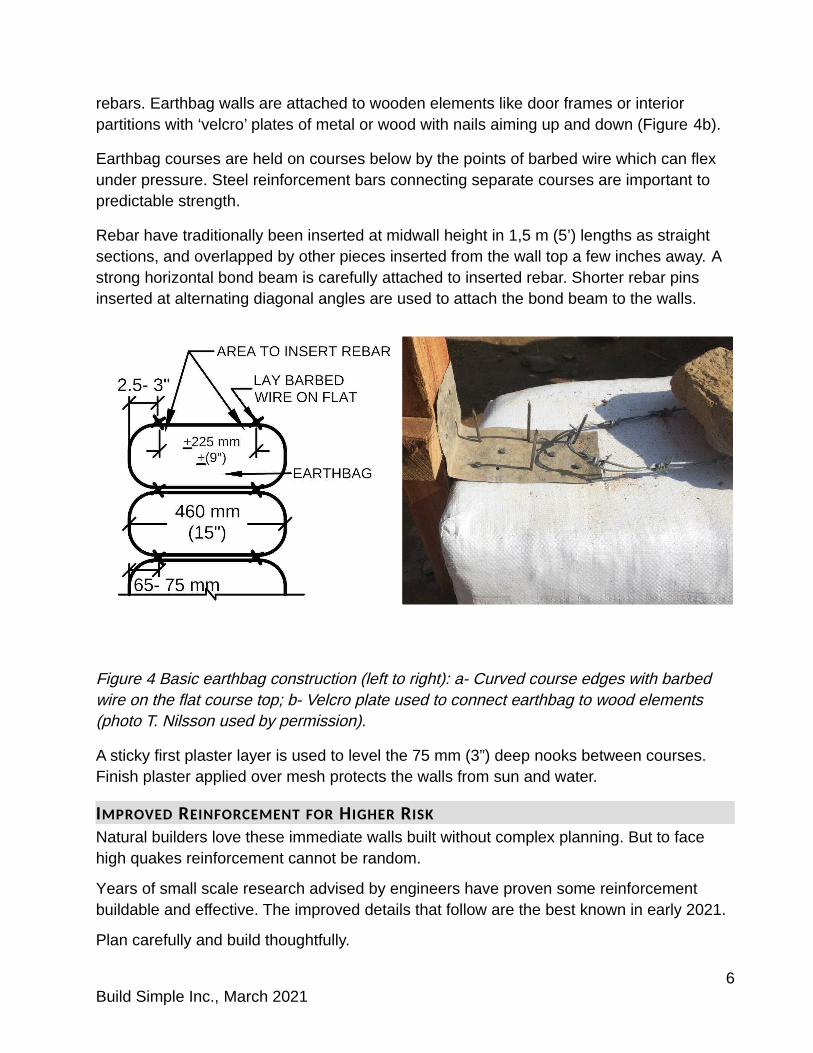
rebars. Earthbag walls are attached to wooden elements like door frames or interior partitions with ‘velcro’ plates of metal or wood with nails aiming up and down (Figure 4b).
Earthbag courses are held on courses below by the points of barbed wire which can flex under pressure. Steel reinforcement bars connecting separate courses are important to predictable strength.
Rebar have traditionally been inserted at midwall height in 1,5 m (5’) lengths as straight sections, and overlapped by other pieces inserted from the wall top a few inches away. A strong horizontal bond beam is carefully attached to inserted rebar. Shorter rebar pins inserted at alternating diagonal angles are used to attach the bond beam to the walls.
Figure 4 Basic earthbag construction (left to right): a- Curved course edges with barbed wire on the flat course top; b- Velcro plate used to connect earthbag to wood elements (photo T. Nilsson used by permission).
A sticky first plaster layer is used to level the 75 mm (3”) deep nooks between courses. Finish plaster applied over mesh protects the walls from sun and water.
IMPROVED REINFORCEMENT FOR HIGHER RISK
Natural builders love these immediate walls built without complex planning. But to face high quakes reinforcement cannot be random.
Years of small scale research advised by engineers have proven some reinforcement buildable and effective. The improved details that follow are the best known in early 2021.
Plan carefully and build thoughtfully.
6Build Simple Inc., March 2021
For higher seismic risk use:
1,7 MPa (250 psi) compressive strength soil fill or higher special care to completely interconnect all the reinforcement
WHERE IS SEISMIC RISK ‘HIGH’?
Earthquake risk can only be estimated.
Scientists use history of earthquakes and local bedrock conditions, and then government officials choose what level of motion they want buildings to resist.
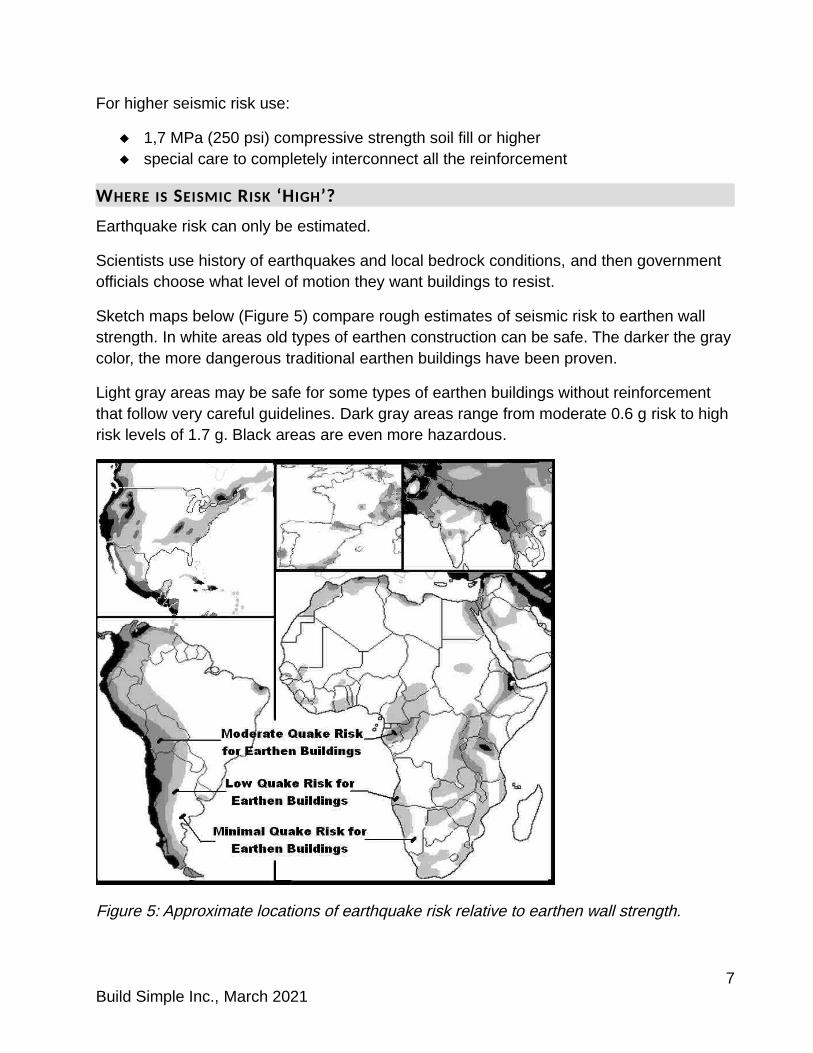
Sketch maps below (Figure 5) compare rough estimates of seismic risk to earthen wall strength. In white areas old types of earthen construction can be safe. The darker the graycolor, the more dangerous traditional earthen buildings have been proven.
Light gray areas may be safe for some types of earthen buildings without reinforcement that follow very careful guidelines. Dark gray areas range from moderate 0.6 g risk to high risk levels of 1.7 g. Black areas are even more hazardous.
Figure 5: Approximate locations of earthquake risk relative to earthen wall strength.
7Build Simple Inc., March 2021

The US, Canada, Europe and Australia have detailed risk maps online. Many areas have accurate recent risk maps online. Get current information about your level of risk. Builders in areas with seismic risk can always benefit from engineering advice and/ or special design help.
This author uses force levels based on US and Australian standards so that designers canmore easily relate earthbag to existing examples of earthen building standards.
HIGH RISK IS:
1.1- 1.7 g (gravity) peak ground acceleration (pga)
occurring in quick ‘Ss’ pulses of 0.2 second (that cause the most damage to low-rise buildings)
likelihood of 2% probability of excedance (pe) in 50 years.
Professionals in different countries use different scales to measure risk. The 10% in 50 year probability of excedance is used in Europe and seen in the online world maps in the Global Earthquake Model (GEM)1, using lower numbers for the same risk. To compare the sketch map above to more detailed maps for the GEM or European codes:
HIGH RISK PROBABILITYOF EXCEDANCE MEASUREMENT COLOR
BSI risk maps2 2% in 50 years >1.1 g pga dark grayGEM hazard maps 10% in 50 years >+ 0.2 g pga yellow
VERY HIGH RISK:BSI risk maps3 2% in 50 years >1.7 g pga blackGEM hazard maps 10% in 50 years + 0.35 g pga yellow-orange
A building code for highly seismic New Zealand was developed based on structural testing. Earth Buildings not Requiring Specific Engineering (NZS 4299:1998) is a resourcefor designers with accurate information for adobe block or rammed earth. A more recent revision (NZS 4299:2020) reflects quality information for CEB (compressed earth block).
Earthbag research to date has not yet proven exactly how earthbag wall strength compares to the materials used in New Zealand’s code. Results imply that earthbag with conventional reinforcement is both stronger and less brittle than unreinforced adobe walls.This means many types of CE may be safe in areas with seismic risk of 0.6- 0.8 g forces.
1 Global Earthquake Hazard and Risk Model online at https://www.globalquakemodel.org/gem 2 https://buildsimple.org/BSI_Risk _Map3 https://buildsimple.org/BSI_Risk _Map
8Build Simple Inc., March 2021

If engineers can consider the high ductility (a type of flexibility that helps buildings survive continuing motion from earthquakes) shown by earthbag research, reinforced adobe walls following NZ guidelines can still resist more force than conventional earthbag. Build Simple Inc. hopes in the future to know how resilient CE earthbag relates to the New Zealand earthen building wall strengths for use in seismic risk areas of 1 g or more.
WHAT STRENGTH OF QUAKE CAN EARTHBAG SURVIVE?
To date engineers can only estimate actual strengths of resilient contained earth with high strength details4. For current structural test results check BuildSimple.org or email [email protected].
Earthen walls are usually brittle, but earthbag shows toughness and flexibility. No anecdotes can prove earthbag’s ability to survive earthquakes, but one serious accident inrural Nepal ended well. A heavy truck drove off of a steep hill top. The vehicle ended up ontop of an earthbag residence (Figure 6). This 1.5 story building had earthbag walls and a welded tubular steel floor structure.
After the accident, the roof had to be rebuilt but walls were not damaged.
Figure 6: Roof was damaged but not the earthbag walls by this truck accident (C. Ziegler, used by permission).
4 Test strength results to date are based on 60% scale testing of earth-plastered samples with scale-reducedrebar and 80% scale testing of unplastered samples with faulty reinforcement underestimated resilient CE. Tests either allowed rebar to rotate at the base attachment or connections at the bond beam failed, so future testing with better full-scale reinforcement may perform better.
9Build Simple Inc., March 2021
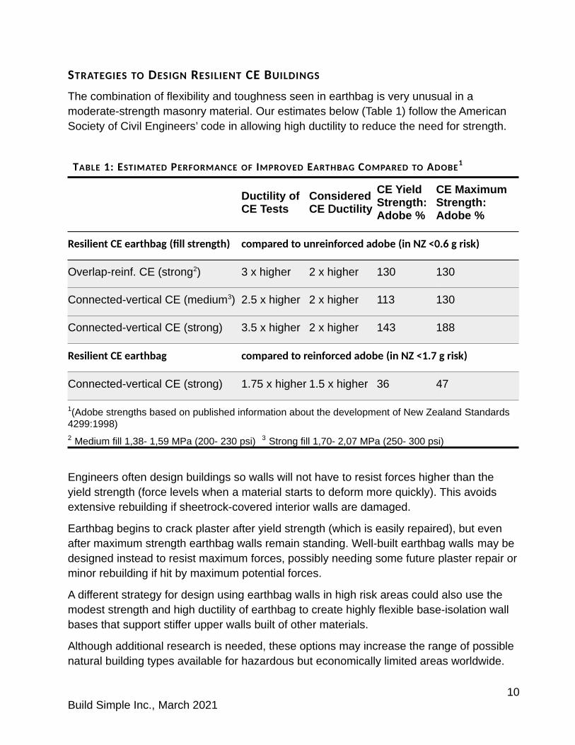
STRATEGIES TO DESIGN RESILIENT CE BUILDINGS
The combination of flexibility and toughness seen in earthbag is very unusual in a moderate-strength masonry material. Our estimates below (Table 1) follow the American Society of Civil Engineers’ code in allowing high ductility to reduce the need for strength.
TABLE 1: ESTIMATED PERFORMANCE OF IMPROVED EARTHBAG COMPARED TO ADOBE1
Ductility of CE Tests
Considered CE Ductility
CE Yield Strength: Adobe %
CE Maximum Strength: Adobe %
Resilient CE earthbag (fill strength) compared to unreinforced adobe (in NZ <0.6 g risk)
Overlap-reinf. CE (strong2) 3 x higher 2 x higher 130 130
Connected-vertical CE (medium3) 2.5 x higher 2 x higher 113 130
Connected-vertical CE (strong) 3.5 x higher 2 x higher 143 188
Resilient CE earthbag compared to reinforced adobe (in NZ <1.7 g risk)
Connected-vertical CE (strong) 1.75 x higher 1.5 x higher 36 47
1(Adobe strengths based on published information about the development of New Zealand Standards 4299:1998) 2 Medium fill 1,38- 1,59 MPa (200- 230 psi) 3 Strong fill 1,70- 2,07 MPa (250- 300 psi)
Engineers often design buildings so walls will not have to resist forces higher than the yield strength (force levels when a material starts to deform more quickly). This avoids extensive rebuilding if sheetrock-covered interior walls are damaged.
Earthbag begins to crack plaster after yield strength (which is easily repaired), but even after maximum strength earthbag walls remain standing. Well-built earthbag walls may be designed instead to resist maximum forces, possibly needing some future plaster repair orminor rebuilding if hit by maximum potential forces.
A different strategy for design using earthbag walls in high risk areas could also use the modest strength and high ductility of earthbag to create highly flexible base-isolation wall bases that support stiffer upper walls built of other materials.
Although additional research is needed, these options may increase the range of possible natural building types available for hazardous but economically limited areas worldwide.
10Build Simple Inc., March 2021
RESILIENT CE EARTHBAG REINFORCEMENT SYSTEMS
Buildings begin to fail when a single weak element breaks or separates first. All parts of a building must be chosen with similar strengths.
Use a system of reinforcement with multiple elements of matched similar strength. Other resilient CE reinforcement systems are described online at BuildSimple.org/ Resources. Use Low-cement CE for low seismic risk and Standard Grade for moderate risk.
Some optional details are included with each reinforcement system. Quality buildings at each strength level can be built without using the more complex optional details.
For the high strength CE reinforcement system, one of the optional details may be very important. Steel opening frames (see section 11, pp. 61- 62) when combined with trussed buttresses may provide enough additional stiffening to allow design of resilient contained earth buildings for higher seismic risk areas where flexible buildings are not usually encouraged.
In addition, designers may use extra vertical rebars more closely spaced like used in the New Zealand non-engineered standards to allow heavier roofs and lofts.
The most important differences between the Low-cement, Standard, and High Strength systems of reinforcement are their foundation construction (Table 2). Low-cement CE has no rigid footings while Standard Grade uses spot footings only at corners. High Strength uses a continuous concrete strip footing that confines a wider gravel bag base.
At this time, all resilient CE reinforcement systems rely on embedded rebar because theseelements stiffen earthbag’s extremely flexible walls. Hiperadobe technique using mesh tubing that allows walls to dry as monolithic would be a better choice if builders must limit embedded steel reinforing bars, but hiperadobe strengths have not been adequately tested.
11Build Simple Inc., March 2021

TABLE 2: COMPARING REINFORCMENT SYSTEMS FOR RESILIENT CE
Low-Cement Standard Grade High-Strength
Footings Gravel bag RC spot at corners RC strip entire length
Base Wall Detached angled pins Covered splices Continuous verticals
Corners Open splice + fork Continuous verticals Continuous verticals and buttresses with trussing
Wall Inter- sections
Open splice/fork Open splice Continuous verticals
Techniques Punched Punched and cut Punched and cut
Rebar Mostly inserted Spliced @ doorways Continuous or spliced
Windows Lap from bond bm Connect one vertical to bond bm
Continuous to bond beam
Doorways Connect to bond bm Connect verticals to
bond bmContinuous to bond beam
Lintels Wood RC or wood RC or wood
Bond Beam Wood RC or steel (wood with ceiling diaphragm)
RC (steel with ceiling diaphragm)
NOTE ABOUT DIMENSIONS
To make this information accessible for builders worldwide, both metric and imperial units are used. In some cases illustrations contain only imperial units because they require less room in the image.
When the measurement is an approximate one, both metric and imperial units are rounded even though they are not exactly equal.
12Build Simple Inc., March 2021

2 MATERIALS FOR RESILIENT CE EARTHBAG
Earthbag building walls are more than 95% natural soil fill. Manufactured materials used, including fabric tubes, wire, cord and rebar, are common and widely available.
CONTAINED EARTH (CE) SOIL FILL
Take care choosing soil fill because for every 15 m (50’) of building walls workers will needto transport, stir and lift almost 27 tons (30 US tons) of it.
Use subsoil. Leave valuable topsoil for agriculture. Stir a handful of building soil into a cup of water. Subsoil will all sink. If much material floats on top of the water, it includes organic material found in topsoil. Dig deeper for your fill, under the topsoil.
Natural soil fill can contain gravel but must be cohesive enough to hold together when dried. Unless building soil is tested by an engineer, or purchased from a source that has already tested it, check the qualities and prove the strength of soil proposed for building.
CHECKING SOIL BY HANDLING
Pinch some damp soil. Pinch and open your fingers (Figure 7a).
COHESIVE SOIL WILL:
Stick to the upper finger
Not just brush off when dry, but must be washed off
Get the pinch wetter and rub it between your fingers.
SOIL WITH SAND (AND/ OR SMALL GRAVEL) is easy to build with and:
Feels gritty like salt between your fingertips
Hand texturing soil shows its cohesion. Squeeze a large handful of barely damp fill into a lump. Squeeze it in one hand to push a ribbon out between thumb and forefinger, a little thicker than your thumb (Figure 7b,c). How long will this ribbon hang before breaking? Repeat to find average performance.
RIBBON LENGTH TYPE OF SOIL
<12 mm (half inch) Little cohesion
12- 20 mm (half to 7/8 inch) Minimum cohesion for building (sandy or silty)
25- 37 mm (one to 1.5 inch) Good cohesion (loam soil)
>37 mm (1.5 inch) High cohesion (clay soil)
13Build Simple Inc., March 2021

Figure 7 Handling soil (left to right): a- Cohesive soil sticks; b- Sandy texture soil drops off after 12 mm (half inch); c- Loam soil with good cohesion drops off after >25 mm (an inch).
The most important quality is how the fill acts in a bag. If a damp gritty soil doesn’t stick together well in hand testing, try tamping it in a bag. The soil inside should hold together. After it dries for 24 hours, use a piece of metal under it and turn the bag gently over. Cohesive soil with some strength is usually firm enough to turn without the fill inside breaking up or crumbling.
Soil fill may be cohesive enough for earthbag. But to create high quality resilient CE for a hazardous area soil must be proven strong enough.
Stronger soil fill creates stronger and stiffer walls. New Zealand requires 1,3 Mpa (190 psi)compressive strength fill for standard grade adobe but to reach good resilient CE strengths builders need 2,1 MPa (300 psi) soil or stronger.
Soil strength can only be tested when completely dry. Large samples can take a month or more to dry but estimates can be made with fist sized samples that can be dried in a day (see section 3 for soil fill strength tests).
STABILIZED EARTHEN FILL
Chemical stabilizers like Portland cement can increase the strength of wall masses, but thick earthbag walls require a very large amount of cement. Labor is also increased to measure and mix fill, and material must be built quickly or discarded. Stabilizers also prevent inserting steel.
Stabilized cohesive soil fill can be used for water-resistant base courses where gravel is not available, but has less potential for damping vibrations than gravel.
GRAVEL BAGS
Wall bases of gravel fill use doubled long bags of fabric or single short tubes of strong mesh. Settle the fill but don’t overfill because gravel does not compress during tamping.
14Build Simple Inc., March 2021

REINFORCED CONCRETE
Some reinforced concrete is needed in footings to reduce risk of soil cracking or subsidingand to decrease wall warping in earthquakes. Mix using clean washed sand in proportionsapproved by experts. Use as little concrete as possible, but use enough cement in it.
CONTAINERS
SMOOTH WOVEN FABRIC
The most common containers for earthbag are woven of flat polypropylene strands about 2mm wide. This breathable fabric is common in grain bags and allows earthen masses inside the walls to dry out gradually. The smooth fabric causes low friction between courses so that CE walls flex rather than crack. Barbed wire barbs and embedded steel rebar bridge the fabric surfaces between courses to make CE a composite metal and natural soil layered wall.
Fabric containers may help walls to resist bulging outward from sideways forces but do notincrease wall strength. Use good condition fabric and protect from sun damage by plastering early- in the tropics or at high altitudes within 2 weeks. After wall fill dries fabric prevents material loss if walls are damaged, keeping walls standing.
Fabric is available in bags or tubes, but use tubes for best integration of reinforcement with walls.
Mesh tubes are not recommended at this time for walls in moderate to high seismic risk because their monolithic wall material may be less ductile than traditional earthbag, and has not yet been as fully researched.
CONTAINER SIZES
Measure tube sizes laid flat. 460 mm (18”) wide tubes are standard for small buildings.
Wall thickness varies based on how high courses are built. Holding tubes more upright during filling produces taller courses. 460 mm (18”) tubes can produce either:
WALL THICKNESS COURSE BEFORE TAMPING COURSE AFTER TAMPING
380 mm (15”) 130 mm (6”) high 125 mm (5”) high
370 mm (14.5”) 178 mm (7”) high 150 mm (6”) high
15Build Simple Inc., March 2021

REINFORCEMENT
Non-biodegradable reinforcement inside earthen walls lasts for generations, but in warm climates insects can damage elements made of bamboo or other natural materials.
Steel and plastic will not be eaten. For increased longevity rebar in contact with soil can be coated with a rust-resistant but non-slippery paint.
Fiberglass and basalt reinforcement are not usable if they lack surface texturing, cannot be bent to produce critical end hooks or cannot have bolts or cross-pieces welded on.
STEEL REBAR
Use only ‘deformed’ (textured) rebar for good bond with dried soil.
D10 (3/8”) rebar allows easy bending and can be used for short pins. If bending before inserting, always bend to 90° to allow hammering to insert.
D12 (half-inch) diameter steel rebar is common for longer vertical reinforcement. Thicker diameter steel may increase wall strength when stiffly anchored in footings.
BARBED WIRE
Use only 4-point galvanized. High tensile strength wire costs less and is common. Low-strength barbed wire which has longer barbs may be used at potential stress points to increase resistance to warping.
STRAPPING OR TIE CORDS
Use common polypropylene electrician’s pull cord or other lightweight non-biodegradable twine able to resist about 90 kg (200 lbs) pull force. Unless builders are experienced in earthbag with enough labor to complete the project quickly, strapping should be UV resistant. Knots must cinch tight and not slip, or use and heat seal packaging straps.
16Build Simple Inc., March 2021
OTHER MATERIALS
PLASTER MESH
Avoid chicken wire which rusts in contact with alkaline cement stucco or lime plaster. Plastic geomesh or fencing mesh may be too costly. Weak plastic bird netting or fishing net is less costly and results in a fine grid which transmits forces well when embedded in plaster.
PLASTER OR STUCCO
Cover all walls with a finish coating to protect bags from sun damage and wall material from water.
Use a sticky first plaster layer to level the 75 mm (3”) deep nooks between courses. If the finish coat will be cement stucco, use a sticky earthen plaster stabilized with 4- 8% Portland cement or hydraulic lime. Stabilized earthen plaster reduces future stucco damage because it shrinks and swells with temperature changes similar to stucco.
Earthen walls reach full strength when fully dry and can survive some dampness if allowedto dry between wettings. In damp climates use a good roof overhang to reduce the amount of wetting. Plaster made from hydraulic lime allows earthen walls to dry better than cement stucco which holds dampness. Consider using lime or earthen plaster on an upper interior area of all raw earthen walls in humid regions even when the majority of the surfaces are finished with cement stucco.
17Build Simple Inc., March 2021

3 PROVING SOIL FILL STRENGTH
Be sure your soil is strong enough before choosing a plan and reinforcement type.
Soil fill can be modified to make it easier to build or to be stronger. Added sand and/ or small gravel can reduce stickiness or shrinking in smooth soils. Adding strong clay to a soilthat is not very sticky can increase fill strength.
Construction is quicker if you can use a local soil that proves strong. Modified fill soil must be measured, have additions mixed in and be stirred in batches, increasing time to build.
SLOW WAYS TO FIND OUT FILL STRENGTH:
Earthen building materials do not reach full strength until fully dry. Large samples must dryout of the rain for up to two months.
An accurate proof of strength that engineers prefer requires at least three full-sized building units crushed under laboratory equipment for unconfined compressive strength.
When a builder has time before building but can’t find a lab to do a compressive strength test, estimate strength by dropping dry, full-sized or 80% scale samples (Figure 8a).
DROPPED FROM THIS HEIGHT IF IT PASSES IT IS THIS STRONG OR MORE :
0,9 m (35”) 1,3 Mpa (190 psi)
1,4 m (56”) 2,1 Mpa (300 psi)
Prepare five or more samples, cut the bags off, and mark 100 mm (4”) from one corner (Figure 8b). Hold the bare sample with the corner aiming down. Drop one sample at a timefrom the correct height (Figure 8c) onto a hard surface.
A sample passes if it doesn’t lose more than 100 mm (4”) off a corner and doesn’t break intwo. Write a list of the height the sample was dropped and the condition of the sample after dropping.
Use the average result. If three out of five samples pass, that is the average strength.
If a sample is not damaged when dropped from a 0,9 m (35”) height, do not reuse it to drop from the greater height. Dropping once can cause tiny fractures and reduce strength so that a higher test is inaccurate.
18Build Simple Inc., March 2021

Figure 8 Drop test large samples: a- 80% scale earthbag size; b- Remove bag and mark distance from corner; c- drop from the correct height.
QUICK WAYS TO ESTIMATE FILL STRENGTH:
Smaller samples can be crushed underfoot or under a simple home-made lever after drying for one day.
For small samples, soil cannot contain gravel. Remove any gravel 2 mm or larger from thefill. Dampen the soil a little, and shape small samples that can be dried within a day.
Dry samples in the shade for a few hours, then place in an oven at 93° C (200° F) until thewhole batch doesn’t get any lighter (check the batch with a kitchen scale every half hour).
BALL CRUSH METHOD
Make twenty balls. Be careful to make them the same 30 mm diameter. These samples can be slightly flattened instead of a perfect ball. When dried compare them to circles or bottle caps the right size (Figure 9a). Reject samples that are too small or too big.
Find someone light and add weight to their pockets or in a backpack until they weigh 60 kg (132 lb).
Test at least ten balls and write the results on a list.
The tester wears a rubber-soled shoe and stands (without twisting) with their heel on a single ball. They slowly lift their toe up to shift weight onto the ball. Then lift the other foot off the ground (Figure 9b). Holding on to a person or wall is good for balance, but let go to put all the weight on the sample.
If a ball does not crush, good! It is minimum strength for resilient CE.
19Build Simple Inc., March 2021
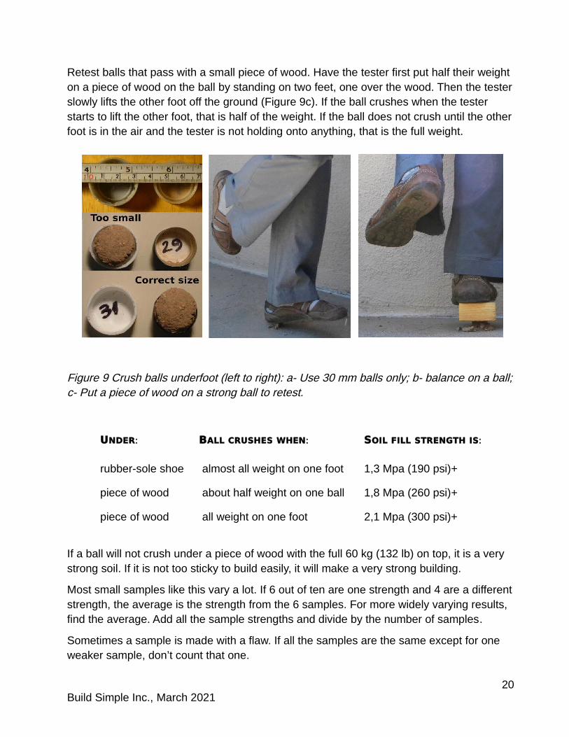
Retest balls that pass with a small piece of wood. Have the tester first put half their weight on a piece of wood on the ball by standing on two feet, one over the wood. Then the testerslowly lifts the other foot off the ground (Figure 9c). If the ball crushes when the tester starts to lift the other foot, that is half of the weight. If the ball does not crush until the otherfoot is in the air and the tester is not holding onto anything, that is the full weight.
Figure 9 Crush balls underfoot (left to right): a- Use 30 mm balls only; b- balance on a ball;c- Put a piece of wood on a strong ball to retest.
UNDER: BALL CRUSHES WHEN: SOIL FILL STRENGTH IS:
rubber-sole shoe almost all weight on one foot 1,3 Mpa (190 psi)+
piece of wood about half weight on one ball 1,8 Mpa (260 psi)+
piece of wood all weight on one foot 2,1 Mpa (300 psi)+
If a ball will not crush under a piece of wood with the full 60 kg (132 lb) on top, it is a very strong soil. If it is not too sticky to build easily, it will make a very strong building.
Most small samples like this vary a lot. If 6 out of ten are one strength and 4 are a differentstrength, the average is the strength from the 6 samples. For more widely varying results, find the average. Add all the sample strengths and divide by the number of samples.
Sometimes a sample is made with a flaw. If all the samples are the same except for one weaker sample, don’t count that one.
20Build Simple Inc., March 2021
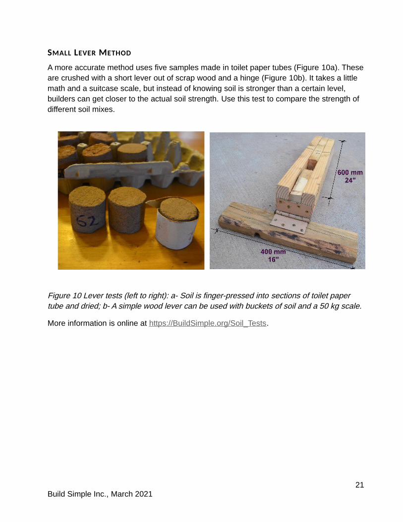
SMALL LEVER METHOD
A more accurate method uses five samples made in toilet paper tubes (Figure 10a). Theseare crushed with a short lever out of scrap wood and a hinge (Figure 10b). It takes a little math and a suitcase scale, but instead of knowing soil is stronger than a certain level, builders can get closer to the actual soil strength. Use this test to compare the strength of different soil mixes.
Figure 10 Lever tests (left to right): a- Soil is finger-pressed into sections of toilet paper tube and dried; b- A simple wood lever can be used with buckets of soil and a 50 kg scale.
More information is online at https://BuildSimple.org/Soil_Tests.
21Build Simple Inc., March 2021

PART II: HIGH STRENGTH RESILIENT REINFORCEMENT SYSTEM
4 THE BASICS OF RESILIENT CE FOR MODERATE TO HIGH RISK
High strength resilient CE earthbag detailing (Figure 11) uses more and stiffer connectionsthan other kinds of CE. For high strength use:
A confining RC strip that surrounds gravel bag footings
Vertical pins anchored in the RC strip
Continuous rebars anchored in the wall base connected directly to the bond beam
Buttresses at external corners that include trussed diagonal rebars to stiffly connect horizontal bond beam steel to vertical wall steel
Figure 11: Improved reinforcement system for highest strength requires Portland cement for footings.
22Build Simple Inc., March 2021

Additional wall strength (Figure 12) also results from:
Diagonal rebar inserted from lintels to stiffen small wall panels Trussed rebar diagonals between lintels and the bond beam over large wall
openings
Figure 12: Optional techniques include trussed rebars above large window or door openings and at corners with half-height piers.
When extra wall strength is needed builders may choose to use one additional important detail: optional welded steel opening frames (see section 11, pp. 61- 62). Because steel strength is more easily proven than earthen walls, steel frames may be helpful in locationswhere code officials or engineers are not allowed to use (or are unfamiliar with) ductility factors when designing masonry walls.
Ductility is an engineering term for a measured level of flexibility that delays damage. Many builders think of earthbag as best when it is not stiff, so that walls can flex and survive earthquakes without breaking. But conventional earthbag is overly flexible, closer to pudding than to steel springs.
Adding reinforcement that stiffly connects rebars in contained earth walls increases the toughness of these walls by reducing the amount of deformation that different levels of force cause. Stiffening earthbag reinforcement connections does not make it brittle, but brings its performance closer to that of a strong steel spring that can recoil without damage.
23Build Simple Inc., March 2021

5 PLANS FOR RESILIENT CE
Earthen walls do not have to be as strong as poured concrete walls. They only need to be strong enough to keep adjacent earthen walls upright.
The shape of a building influences how strong its walls need to be.
BUILDINGS THAT NEED MORE STRENGTH BUILDINGS THAT NEED LESS STRENGTH
Large buildings, large rooms Small buildings, small rooms
Long, narrow buildings (>3:1) Square or rectangular buildings (1:1- 2.5:1)
Taller, heavier walls Shorter, lighter walls
Asymmetrical or irregular shapes Symmetrical and compact shapes
Rectangular corners Curving walls
Crowded or irregular openings Regular, well-spaced windows and doors
DON’T USE: DO USE:
Oversized wall openings for picture windows Upright windows <1,2 m (4’) wide
Large gaps in walls Framed wall openings <1,5 m (5’)
Chimney or gable of heavy materials Light materials only above the bond beam
L shaped buildings Two separate compact-shape buildings
Even though resilient CE earthbag walls are tough and flexible rather than brittle, as muchas possible choose building shapes that are naturally more resistant to earthquake forces.
Reinforcement levels should be based on the overall building size and the weight resting on the wall tops from lofts or heavy roofs.
Buildings with more than 1,5 m (5’) between windows can use a rule of thumb to include additional vertical reinforcement at a standard spacing. Traditional earthbag builders used rebar every 1,2 m (4’) on center, and guidelines used in New Zealand specify base-anchored rebar at similar spacings or as close as 1 m (3’3”) on center for buildings needing extra strength.
DISTANCES BETWEEN OPENINGS
Past rules of thumb borrowed from adobe practice are not helpful for earthbag openings.
Crowding openings may bring reinforcement too close together and reduce resistance to quake stresses. Cob testing showed that vertical rebars 0,9 m (3’) apart improved strength, but 300 mm (12”) spacing in both directions reduced strength instead of helping.
24Build Simple Inc., March 2021
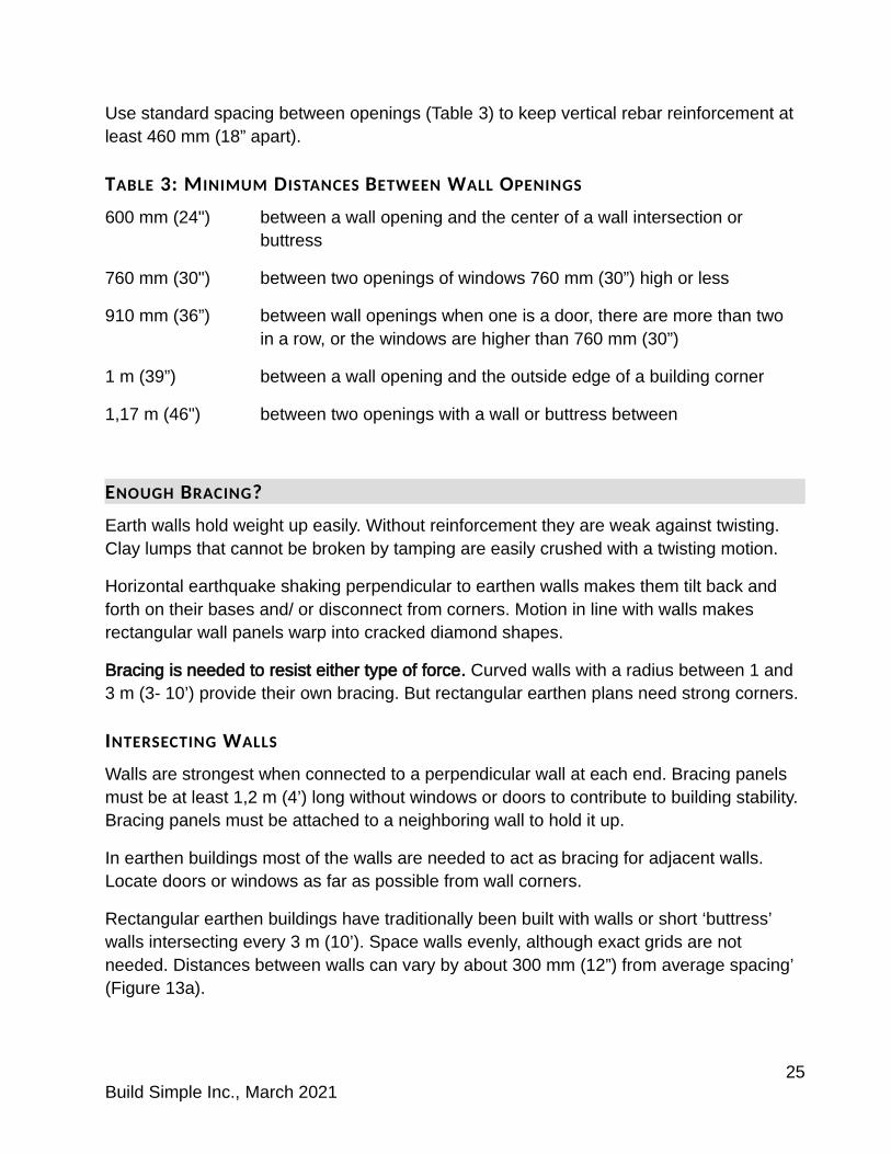
Use standard spacing between openings (Table 3) to keep vertical rebar reinforcement at least 460 mm (18” apart).
TABLE 3: MINIMUM DISTANCES BETWEEN WALL OPENINGS
600 mm (24") between a wall opening and the center of a wall intersection or buttress
760 mm (30") between two openings of windows 760 mm (30”) high or less
910 mm (36”) between wall openings when one is a door, there are more than two in a row, or the windows are higher than 760 mm (30”)
1 m (39”) between a wall opening and the outside edge of a building corner
1,17 m (46") between two openings with a wall or buttress between
ENOUGH BRACING?
Earth walls hold weight up easily. Without reinforcement they are weak against twisting. Clay lumps that cannot be broken by tamping are easily crushed with a twisting motion.
Horizontal earthquake shaking perpendicular to earthen walls makes them tilt back and forth on their bases and/ or disconnect from corners. Motion in line with walls makes rectangular wall panels warp into cracked diamond shapes.
Bracing is needed to resist either type of force. Curved walls with a radius between 1 and 3 m (3- 10’) provide their own bracing. But rectangular earthen plans need strong corners.
INTERSECTING WALLS
Walls are strongest when connected to a perpendicular wall at each end. Bracing panels must be at least 1,2 m (4’) long without windows or doors to contribute to building stability. Bracing panels must be attached to a neighboring wall to hold it up.
In earthen buildings most of the walls are needed to act as bracing for adjacent walls. Locate doors or windows as far as possible from wall corners.
Rectangular earthen buildings have traditionally been built with walls or short ‘buttress’ walls intersecting every 3 m (10’). Space walls evenly, although exact grids are not needed. Distances between walls can vary by about 300 mm (12”) from average spacing’ (Figure 13a).
25Build Simple Inc., March 2021

Good building designers must learn to check if the building has enough bracing panels to hold the adjacent walls up. Use lists and notes on plans to check whether doors or windows are too close to any specific corner (Figure 13b).
Figure 13 Earthen buildings need walls at regular bracing line distances (left to right): a- Average the wall distances if actual spacing is within 300 mm (12”) of the average; b- Are wall panels long enough to brace each wall?
The New Zealand Standards Earth Buildings not Requiring Specific Engineering (4299:1998) has a complex process for non-engineers to check bracing that considers wall thickness, height, and the weight of a loft, upper story or roof. This process designed for code officials has many steps, including calculating total bracing need of each wall, then adding up separately the exact bracing capacity of each wall panel.
A simpler process can be used by designers as illustrated in Figure 13b:
1. Measure the length of the supported wall (including all openings). Note that walls A and B are the same length but wall C is longer because it includes longer buttresses.
2. Measure all the connected wall sections perpendicular to each supported wall but do not include doors or windows. Wall A is supported by panels A1, A2 and A3. Note that panel A1 is measured to the middle of the distance between walls A and B. If any panel is less than 1,2 m (4’) in length it is too short to help brace the building.
26Build Simple Inc., March 2021

3. Find a table or chart based on the strength of your wall fill and reinforcement5- ask an engineer how long bracing walls need to be for each length of supported wall.
4. Adjust bracing amounts for each wall by moving or narrowing doors or windows or by extending buttresses. If wall A in Figure 13b needs more bracing, buttresses in A1 and A3 can be lengthened, the door in panel A3 can be moved further from Wall A, and panel A2 could extend into the room.
When bracing walls are spaced further apart, the bracing panels need to be longer. Early earthbag builders managed the unusual wall flexibility with short bracing distances of 3 m (9’- 9”). An alternative is to use a longer distance between walls and then to add buttresses between them to stiffen walls (Figure 14a).
Most contained earth buildings for high seismic risk areas benefit from buttresses at all external wall ends and at corners to add extra stability (Figure 14b).
Figure 14 Bracing panels increase strength (top to bottom): a- a little with a few buttressesbetween walls; b- More with buttresses extending from most wall ends.
Buttresses, like any stub walls, should extend out from walls between 500 mm (20”) and 1,2 m (4’). Buttresses less than 500 mm (20”) long require a short bag that does not receive enough barbed wire barbs and wall weight to attach well into the wall. Buttresses plus aligned walls must be 1,2 m (4’) long or more to add significantly to the building’s bracing capacity. Shorter lengths are too easily damaged. But stub walls extending further from their intersecting wall than 1,2 m (4’) can reduce wall stability.
5 The Standard Grade Resilient CE booklet includes some tables of basic bracing wall lengths needed for 2,4 m (7’- 11”) height walls for different bracing wall spacing distances in seismic risk areas up to 1 g. Those tables are based on loose estimates of CE wall strength from limited testing. This author hopes in the future to provide similar tables to use in higher seismic risk areas. Until better research has been completed, ask engineers for advice.
27Build Simple Inc., March 2021
Some specifics of the New Zealand code includes the fact that generally well-braced buildings can use 30% less bracing panels on just one of the bracing lines. But other recommendations are more restrictive, and include bracing walls lengthened by:
35% for interior walls compared to exterior at 3 m (10’) bracing line spacing
42% for interior walls at 4,5 m (15’) spacing
12% for walls 2,7 m (8’- 11”) height compared to 2,4 m (7’- 11”) height
15% for walls 3 m (9’- 10”) height compared to 2,4 m (7’- 11”) height
Professional advice can consider these types of complex requirements for a particular building and may reduce building costs and save lives.
28Build Simple Inc., March 2021
6 FOOTINGS FOR MODERATE TO HIGH RISK
Reinforced concrete (RC) in foundations are critical to resist damage from stronger earthquakes. RC footings connect more wall weight to resist uplift. The bottom hook embedded in concrete also stiffens rebar against wall warping.
Earthen buildings with 380 mm (15”) thick walls require a lot of cement for footings 430 mm (17”) or wider. Instead use a narrower reinforced concrete strip and unite it strongly to gravel bags. Gravel bags alone can be used for the foundations of many interior walls.
Resilient CE walls are tough and flexible so their footings can allow vertical flexing. Strength in footings comes from the size of the steel reinforcement more than from the depth or width of concrete. Footings 125 mm (5”) deep will be less stiff against vertical motion than thicker footings.
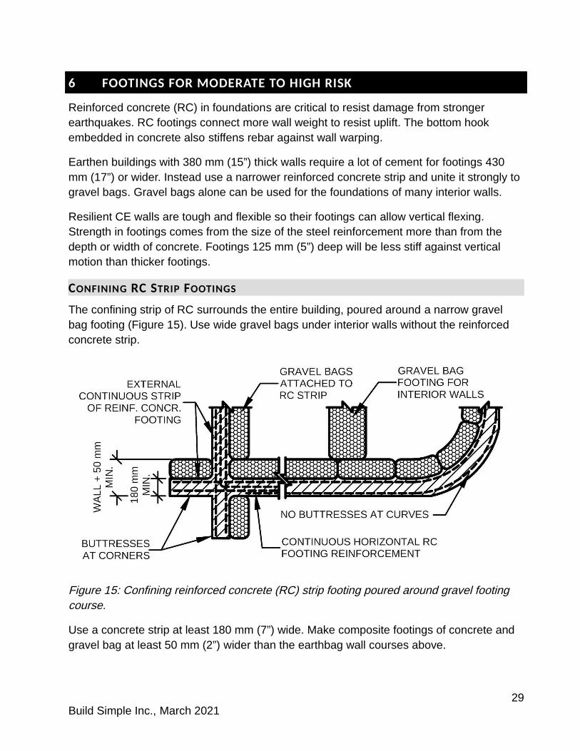
CONFINING RC STRIP FOOTINGS
The confining strip of RC surrounds the entire building, poured around a narrow gravel bag footing (Figure 15). Use wide gravel bags under interior walls without the reinforced concrete strip.
Figure 15: Confining reinforced concrete (RC) strip footing poured around gravel footing course.
Use a concrete strip at least 180 mm (7”) wide. Make composite footings of concrete and gravel bag at least 50 mm (2”) wider than the earthbag wall courses above.
29Build Simple Inc., March 2021
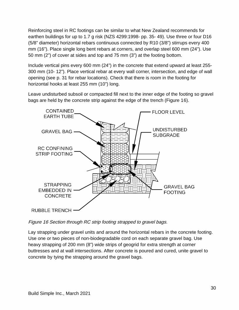
Reinforcing steel in RC footings can be similar to what New Zealand recommends for earthen buildings for up to 1.7 g risk (NZS 4299:1998- pp. 35- 49). Use three or four D16 (5/8” diameter) horizontal rebars continuous connected by R10 (3/8”) stirrups every 400 mm (16”). Place single long bent rebars at corners, and overlap steel 600 mm (24”). Use 50 mm (2”) of cover at sides and top and 75 mm (3”) at the footing bottom.
Include vertical pins every 600 mm (24”) in the concrete that extend upward at least 255- 300 mm (10- 12”). Place vertical rebar at every wall corner, intersection, and edge of wall opening (see p. 31 for rebar locations). Check that there is room in the footing for horizontal hooks at least 255 mm (10”) long.
Leave undisturbed subsoil or compacted fill next to the inner edge of the footing so gravel bags are held by the concrete strip against the edge of the trench (Figure 16).
Figure 16 Section through RC strip footing strapped to gravel bags.
Lay strapping under gravel units and around the horizontal rebars in the concrete footing. Use one or two pieces of non-biodegradable cord on each separate gravel bag. Use heavy strapping of 200 mm (8”) wide strips of geogrid for extra strength at corner buttresses and at wall intersections. After concrete is poured and cured, unite gravel to concrete by tying the strapping around the gravel bags.
30Build Simple Inc., March 2021

Mesh tubing for gravel units next to the footing allows poured concrete to embed the gravel containers. Strong extruded mesh tube like that used in erosion control wattles alsoallows longer gravel units than traditional fabric bags.
CONNECTING GRAVEL BAG FOOTINGS TO RC FOOTINGS
Barbed wire used for gravel bag footing courses must be embedded in the RC strip or in spot footings to unite the separate materials. Wire binding alongside courses connects better than barbed wire on course tops (see section 7, pp. 37- 38 for wire binding techniques).
RC SPOT FOOTINGS
Small houses may be reinforced well enough with strong external walls, but buildings with larger rooms or more rooms need stiffly base-anchored vertical rebar at major wall intersections.
Use 910 mm (3’) square reinforced concrete spot footings at interior wall intersections in buildings larger than 90 m2 (1000 s.f.) or with more than four rooms (Figure 17a).
ANCHORING REBAR IN RC FOOTINGS
Most vertical rebars are located near the external surfaces of the earthen building wall (Figure 17b) and anchored in the reinforced concrete confining strip footing.
Figure 17 Details of RC spot and strip footings (left to right): a- Locate spot footings at intersections of major interior walls; b- Locate vertical rebar 125 mm (5”) in from surfaces of contained earth walls above to provide good embedment of steel in earthen fill.
31Build Simple Inc., March 2021

The standard 125 mm (5”) setback from wall surfaces to vertical rebar allows barbed wire to bend around the rebar in many locations, but gives the rebar enough embedment in thedried soil fill.
Where forms or ‘bucks’ will be used at doorways, windows, or the ends of stub walls, rebars can be located 230 mm (9”) from the form so that a standard tamping tool can fit between the rebar and the form. If this causes rebar crowding in the wall, instead locate the vertical reinforcement 125 mm (5”) from the opening or wall end and use a piece of 100 x 100 (4 x 4) to tamp between the rebar and the form.
FULL RC FOOTINGS
Full-width reinforced concrete (RC) footings may be needed in locations with more risk of subsoil loss:
near steep slopes or erosion gullies
in light, poorly compacted soils (sometimes found where streams widen out at the base of mountains)
on very sticky clay soils that crack when dry
near cracked pavement or foundations or leaning trees or posts on slopes
Wider RC footings may also be needed on some types of subsoil.
Footing width spreads building weight out over a strip of soil as wide as the footing. Earthbag building walls weigh twice as much as concrete block, so on some soft or weak soils extra wide footings may be needed. Engineers must choose whether wider footings can be created out of gravel bags under the confining strip, or whether a full-width RC footing is needed.
32Build Simple Inc., March 2021
7 EMBEDDED REINFORCEMENT FOR MODERATE TO HIGH RISK
Builders and designers new to earthbag building should learn from several sources such as a hands-on course, basic Earthbag Information Slide Shows online at BuildSimple.org, and a full-length book like Hart’s, Essential Earthbag Construction. Videos by Geiger online at the Naturalhouses youtube channel also show generally accepted practices.
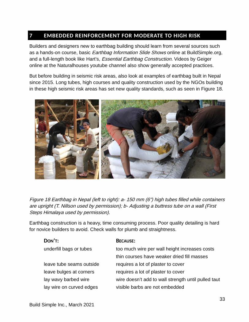
But before building in seismic risk areas, also look at examples of earthbag built in Nepal since 2015. Long tubes, high courses and quality construction used by the NGOs building in these high seismic risk areas has set new quality standards, such as seen in Figure 18.
Figure 18 Earthbag in Nepal (left to right): a- 150 mm (6”) high tubes filled while containersare upright (T. Nillson used by permission); b- Adjusting a buttress tube on a wall (First Steps Himalaya used by permission).
Earthbag construction is a heavy, time consuming process. Poor quality detailing is hard for novice builders to avoid. Check walls for plumb and straightness.
DON’T: BECAUSE:
underfill bags or tubes too much wire per wall height increases costs
thin courses have weaker dried fill masses
leave tube seams outside requires a lot of plaster to cover
leave bulges at corners requires a lot of plaster to cover
lay wavy barbed wire wire doesn’t add to wall strength until pulled taut
lay wire on curved edges visible barbs are not embedded
33Build Simple Inc., March 2021

BETTER BONDING WITH FILL
The bond between dried strong soil and steel is what gives resilient CE the ability to resist earthquakes. Keep soil fill material just damp enough to consolidate well. Tamped coursesmust consolidate without dry crumbs loose in the fabric containers at edges or corners.
Soil fill must also not be damp enough to ‘jelly’ up so that it cannot be tamped. In rainy regions, cover the soil pile when not in use. Put a fussy person in charge of the soil pile. Check frequently for optimum moisture content by dropping a squeezed small handful from 1,5 m (5’). It should split into 2- 3 pieces and not leave a wet mark on the ground.
Barbed wire and pins must be placed on each course immediately after tamping for good bond. Rebar must also be in place as soon as the highest course pierced is tamped.
The ideal time to hammer steel into earthbag walls is within two to three weeks of laying the lowest course that will be pierced. Insert early for the most continuous and strongest bonds between rebar and fill. Although interiors of courses dry slowly for months, the edges of every course begin to dry soon after construction.
New techniques to embed base-anchored rebars result in damp walls being built around steel rebars. This produces continuous high-quality connections between steel and fill.
BEST WALL CONTINUITY
Fine-grained connections spread out forces before they concentrate at damaging levels. Earthbag containers contribute to wall longevity when long sections overlap alternating courses at corners. Use tubes as long as possible in walls. For one course run all east-west walls continuous through the corners or wall crossings. At the next run all north-southwalls continuous (compare Figures 17a and 17b).
Get the most strength from barbed wire by straightening the wire, pulling it taut along straight walls and bending it sharply at corners (Figure 19a). Tack it in place at bends nearopenings (Figure 19b,c). Run at least one strand on every course continuous around the external walls as far as possible.
Use electrician’s staples to tack wires. For extra strength make wire mesh pins cut from strips of mesh. Cut each with three or more teeth. When using mesh pins, bend them just before placing. Pins tangle together if cut and bent ahead of time.
34Build Simple Inc., March 2021

Figure 19 Hold barbed wire in place (left to right): a- Wrap around a vertical rebar; b- Tackwire at corners with an electrician’s staple; d- Tack with pins cut from wire mesh.
After laying exterior wall wire, run straight lengths of wire continuous on interior walls out across the exterior walls where they connect (Figure 20). At the end of a stub wall or near a wall opening, turn wire and return into the wall.
Figure 20 Run barbed wire continuous around corners and near wall ends or openings.
End barbed wire strands with at least a 600 mm (24") overlap (Figure 21) that does not occur at corners or wall openings.
NEVER END A BARBED WIRE STRAND AT A WALL CORNER!
35Build Simple Inc., March 2021
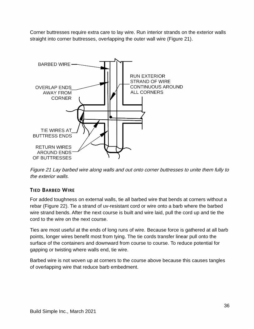
Corner buttresses require extra care to lay wire. Run interior strands on the exterior walls straight into corner buttresses, overlapping the outer wall wire (Figure 21).
Figure 21 Lay barbed wire along walls and out onto corner buttresses to unite them fully tothe exterior walls.
TIED BARBED WIRE
For added toughness on external walls, tie all barbed wire that bends at corners without a rebar (Figure 22). Tie a strand of uv-resistant cord or wire onto a barb where the barbed wire strand bends. After the next course is built and wire laid, pull the cord up and tie the cord to the wire on the next course.
Ties are most useful at the ends of long runs of wire. Because force is gathered at all barbpoints, longer wires benefit most from tying. The tie cords transfer linear pull onto the surface of the containers and downward from course to course. To reduce potential for gapping or twisting where walls end, tie wire.
Barbed wire is not woven up at corners to the course above because this causes tangles of overlapping wire that reduce barb embedment.
36Build Simple Inc., March 2021

Figure 22 Use tie cords to hold barbed wire in place at corners and intersections to unite walls.
GRAVEL BAG FOUNDATIONS AND BASE WALLS
Base walls can be built of gravel bag above the footing as a moisture break. But since gravel fill does not bond with reinforcing rebar, straps and pins are needed to ensure gravel courses hold together well.
Strap all gravel courses vertically from beneath the main footing. Tie the strapping above one or two CE courses on top of the gravel courses. Never strap three or more courses of CE to avoid loose straps if the earthen fill shrinks during drying.
ANGLED BASE WALL PINS IN GRAVEL BAG
When using more than a single course of gravel bags above concrete also:
Insert angled base wall pins through every bag or at least every 600 mm (24”) Bind barbed wire around straight segments of gravel bag interior wall footings
Insert rebar pins at a 30° or steeper angle through at least two courses of contained earth.Start rebars 300 mm (12”) distant from footing pins and all other locations where longer rebars will be inserted above.
BINDING GRAVEL BAG COURSES
Barbed wire laid on gravel-filled courses does not attach strongly to the bags. Instead, run wire around bags (Figure 23a).
Bind any straight lengths of gravel bag courses. Connect wire where strands end by inserting a small nail between the twisted wire of each strand. Lever it to pull the wires taut. Bend the nail and wrap it and the two wires with galvanized tie wire (Figure 23b).
37Build Simple Inc., March 2021

Figure 23 (left to right) Binding gravel bag courses: a- Wrap straight lengths; b- Attach securely.
Or to join wire ends, twist loops around a rebar pin and embed it in a chunck of concrete.
On every course some buttress or stub wall sections cannot be bound (like the buttress onthe top of Figure 24a). On the next course that element will have bags laid in the other direction (Figure 24b) and can be bound.
Figure 24 (right to left): a- Bind around straight lengths of gravel bag courses; b- On alternating courses bind the continous bag or tube lengths.
38Build Simple Inc., March 2021
EMBEDDING REBAR IN CE WALLS
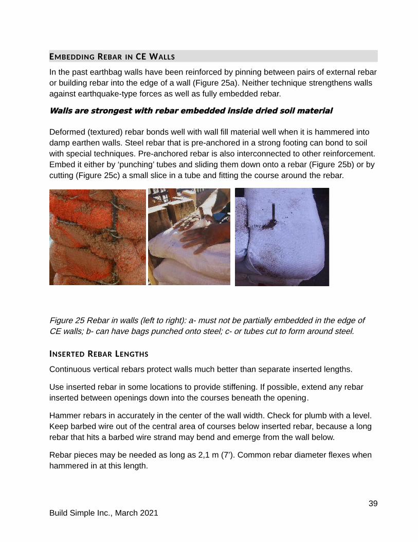
In the past earthbag walls have been reinforced by pinning between pairs of external rebaror building rebar into the edge of a wall (Figure 25a). Neither technique strengthens walls against earthquake-type forces as well as fully embedded rebar.
Walls are strongest with re bar embedded inside dried soil material
Deformed (textured) rebar bonds well with wall fill material well when it is hammered into damp earthen walls. Steel rebar that is pre-anchored in a strong footing can bond to soil with special techniques. Pre-anchored rebar is also interconnected to other reinforcement.Embed it either by ‘punching’ tubes and sliding them down onto a rebar (Figure 25b) or by cutting (Figure 25c) a small slice in a tube and fitting the course around the rebar.
Figure 25 Rebar in walls (left to right): a- must not be partially embedded in the edge of CE walls; b- can have bags punched onto steel; c- or tubes cut to form around steel.
INSERTED REBAR LENGTHS
Continuous vertical rebars protect walls much better than separate inserted lengths.
Use inserted rebar in some locations to provide stiffening. If possible, extend any rebar inserted between openings down into the courses beneath the opening.
Hammer rebars in accurately in the center of the wall width. Check for plumb with a level. Keep barbed wire out of the central area of courses below inserted rebar, because a long rebar that hits a barbed wire strand may bend and emerge from the wall below.
Rebar pieces may be needed as long as 2,1 m (7’). Common rebar diameter flexes when hammered in at this length.
39Build Simple Inc., March 2021

To insert rebars longer than 1,5 m (5’):
Cut the tip at a sharp angle Prepare a guide hole by hammering a narrower smooth steel bar 300 mm (1’) deep
in the correct location and then removing it Hold the rebar in a narrow pipe a little shorter than the exposed rebar while
hammering Use a tool made of a long capped pipe so that workers pull the tool down around
the rebar to insert lengths of steel higher than they can reach
SPACE INSERTED LAP REBARS
Align main inserted rebars one above the other at the location where reinforcement is needed. Use a separate shorter lap rebar that overlaps both the upper and lower verticals (Figure 26). The lap bar is parallel for only a short distance, so lap bars can be closer than460 mm (18”). Space the lap away from the main verticals as far as the length of the overlap.
Figure 26 Align separate inserted rebar lengths where reinforcement is needed but use a shorter lap rebar spaced as far away as the overlap length.
DIAGONAL PINS
Straight rebar lengths inserted at an angle lack stiff anchorage from a bottom hook. But they provide some resistance against upward forces. The weight of the fill is held on the steel by the bond between the dried fill and steel. Use diagonal rebars to connect
40Build Simple Inc., March 2021

elements together (door or window frames to walls, bond beams to walls, piers to main walls) and to stiffen wall panels against bulging damage.
When angled rebars are used aiming in different directions, insert them at least 100 mm (4”) apart on top of the course.
VERTICAL REBAR CONNECTIONS
Rebars do not give maximum strength to walls unless the top stays connected to the bondbeams. Use the correct end on any steel rebar in earthen walls.
HOOKS AT THE REBAR TOP
All major verticals at corners, wall intersections and near wall openings should have 255- 300 mm (10- 12”) long hooks bent on the end that will be embedded in the reinforced concrete bond beam. Reinforcing steel embedded in concrete should always have 25 mm (one inch) of cover or more.
If a hook is bent at 90 degrees the rebar can be hammered into a wall. To make insertion easiest, bend a top hook after inserting a rebar by attaching a heavy pipe wrench on the rebar next to the top of the earthen course. Place a long pipe over the end of the rebar about 75 mm (3”) above the top course so that less force is needed to bend the steel.
Rebars inserted through wood lintels only need a short hook of 75- 100 mm (3- 4”). Because 12- 18 mm (half- ¾ inch) diameter rebar bends safely at a 50 mm (2”) radius, drillan angled hole next to the vertical hole for the pin. Let the curve near the hook sink into the wood so that the hook can snug up to it. Or instead of a hook, weld a perpendicular stub on rebars to be inserted through wood.
BOLTS AT THE REBAR TOP
If a base-anchored main vertical rebar (used at external corners and wall intersections as well as near openings) must be attached to a wood lintel or a steel window frame, weld a strong bolt to the end before anchoring it in the footing.
BASE-ANCHORED REBAR
Rebars pre-anchored in a stiff concrete footing allow earthen walls to survive stronger earthquakes. Embed them in damp earthen CE wall fill using small holes or cuts to fabric.
Punched-bag or cut-bag techniques are equally useful on verticals at corners and wall intersections. For rebars in the middle of straight walls near wall openings use punched-bag as much as possible with some cut-bag technique.
41Build Simple Inc., March 2021

PUNCHED-BAG CONSTRUCTION
Builders slide a partly filled tube down over the top of a rebar.
Place two small cuts in a tube and fill past the holes. Shake and compress the fill. With a finger in the hole on the bottom of the tube (Figure 27a) slide the rebar through the bottomand then through the top hole. With a fist or wood piece re-pack fill in the tube and continue filling (Figure 27b). Tamp around the rebar (Figure 27c).
Figure 27 Punched-bag construction (left to right): a- Cut the hole before filling, then slide a partly-filled tube end over a rebar; b- Continue filling the tube; c- Tamped punched-bag.
Builders can punch through the tube without cutting the hole but fabric frays more (Figures25b and 27b). Small cuts made before punching the rebar leave little fabric damage (Figure 27c) and may speed work.
Prepare standard tube ends where punching many courses. Staple or sew the end of a clean tube, pre-measure and make a small cut. The distance from the end of a flat empty tube must include the curving bag side:
COURSE HEIGHT DISTANCE OF HOLE FROM END OF BAG
125 mm (5”) 37- 50 mm (1.5- 2”) + desired distance from the wall
150 mm (6”) 75 mm (3”) + desired distance from the wall
Patch holes in clean tubes with duct tape before filling if the fill has low cohesion.
Using a punched tube creates a ‘head-joint’ between ends of the tube. This interferes with continuous course lengths in straight wall segments. If using only punched-bag to embed a vertical rebar under a window, alternate the side of the rebar with tube ends at least 150 mm (6”) from the rebar for good overlap distances (Figure 28a).
To reduce the number of head joints, builders can punch tubes onto rebars as much as 380 mm (15”) from the tube end. Under windows heavy punched tubes will reduce the
42Build Simple Inc., March 2021

number of head joints (Figure 28b), but a tube end filled that deeply will weigh 30 kg (65 lbs). Heavy punched tubes may slow or complicate the work process. Punched-bag tubes alternating around a rebar must also be built running in opposite directions.
Figure 28 Punched tubes beneath a window opening (left to right): a- alternate around rebar to maintain minimal overlap distance; b- heavy punched tubes below center of window alternate with head joints near rebar.
When tamping around vertical rebars already anchored in place, be careful to maintain therebar vertical and at the correct distance from openings and/or wall surface.
Bags can only be ‘punched’ onto vertical rebars near the beginning of a tube. A tube that has been punched near the beginning can’t be punched again near the end. Because high-strength resilient CE walls need vertical rebar throughout building walls, punched-bagtechnique is usually combined with cut-bag technique to reduce head-joints.
43Build Simple Inc., March 2021
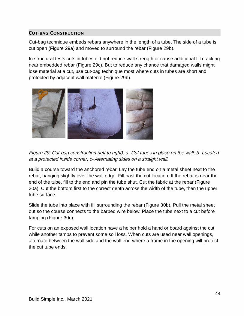
CUT-BAG CONSTRUCTION
Cut-bag technique embeds rebars anywhere in the length of a tube. The side of a tube is cut open (Figure 29a) and moved to surround the rebar (Figure 29b).
In structural tests cuts in tubes did not reduce wall strength or cause additional fill crackingnear embedded rebar (Figure 29c). But to reduce any chance that damaged walls might lose material at a cut, use cut-bag technique most where cuts in tubes are short and protected by adjacent wall material (Figure 29b).
Figure 29: Cut-bag construction (left to right): a- Cut tubes in place on the wall; b- Located at a protected inside corner; c- Alternating sides on a straight wall.
Build a course toward the anchored rebar. Lay the tube end on a metal sheet next to the rebar, hanging slightly over the wall edge. Fill past the cut location. If the rebar is near the end of the tube, fill to the end and pin the tube shut. Cut the fabric at the rebar (Figure 30a). Cut the bottom first to the correct depth across the width of the tube, then the upper tube surface.
Slide the tube into place with fill surrounding the rebar (Figure 30b). Pull the metal sheet out so the course connects to the barbed wire below. Place the tube next to a cut before tamping (Figure 30c).
For cuts on an exposed wall location have a helper hold a hand or board against the cut while another tamps to prevent some soil loss. When cuts are used near wall openings, alternate between the wall side and the wall end where a frame in the opening will protect the cut tube ends.
44Build Simple Inc., March 2021
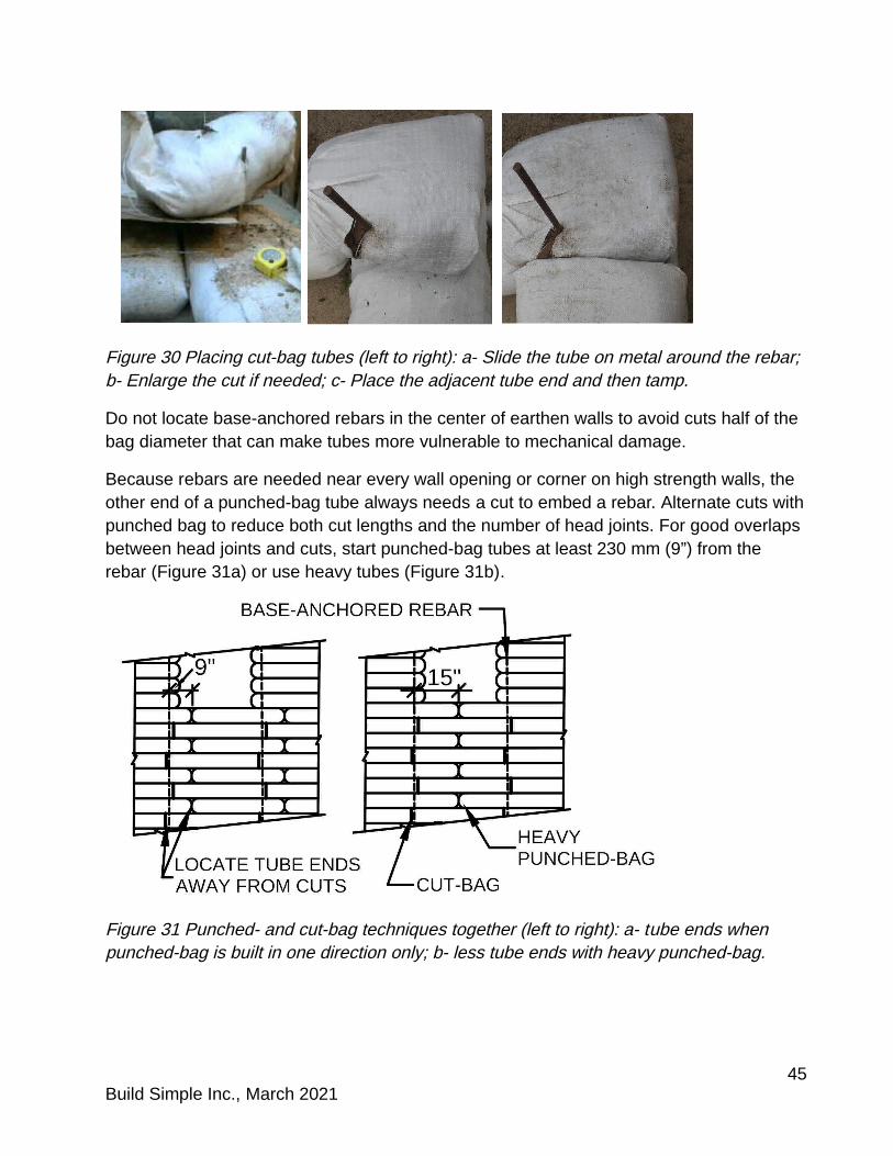
Figure 30 Placing cut-bag tubes (left to right): a- Slide the tube on metal around the rebar; b- Enlarge the cut if needed; c- Place the adjacent tube end and then tamp.
Do not locate base-anchored rebars in the center of earthen walls to avoid cuts half of the bag diameter that can make tubes more vulnerable to mechanical damage.
Because rebars are needed near every wall opening or corner on high strength walls, the other end of a punched-bag tube always needs a cut to embed a rebar. Alternate cuts withpunched bag to reduce both cut lengths and the number of head joints. For good overlaps between head joints and cuts, start punched-bag tubes at least 230 mm (9”) from the rebar (Figure 31a) or use heavy tubes (Figure 31b).
Figure 31 Punched- and cut-bag techniques together (left to right): a- tube ends when punched-bag is built in one direction only; b- less tube ends with heavy punched-bag.
45Build Simple Inc., March 2021
8 INTERCONNECTED WALLS FOR MODERATE TO HIGH RISK
Strong rebar horizontals in the footings and bond beams connected by verticals embedded in the walls are the most important reinforcement in resilient CE buildings. Steel reinforcement must form an interconnected 3D grid.
STRENGTH INCREASES MOST WHEN EMBEDDED REINFORCEMENT IS CONNECTED TO
OTHER EMBEDDED REINFORCEMENT.
Use strong connections, but connection between steel and soil is more important than connections between wire and rebar.
WALL INTERSECTIONS
Where walls cross inside a building, alternate tube direction between courses and also runstraight wires crossing to connect them.
Do not bend wire around all rebars. On interior walls barbed wire should run straight to where the wall ends. Base-anchored rebars in the crossing area at interior wall intersections should not have barbed wire bent around them.
At intersections of walls use embedded rebars to pin the alternating sections together. If there is no continuous vertical from a footing, insert spaced lap rebars in the center of the intersection so that the rebar pins the tubes and earthen fill from course to course.
EXTENDED WALLS, BUTTRESSES AND STUBS
Where interior walls end at the exterior wall they can continue into a buttress.
Any buttress or stub wall must be at least 500 mm (20”) long. Insert lap rebars near the end of the wall element. Limit stub walls and buttresses to 1,2 m (4’) maximum. Full heightbuttresses and stub walls must be included under the bond beam.
Build a stub wall or buttress longer than 1 m (39”) on a strip or full concrete footing and locate a continuous vertical rebar at the end. Use the same width as walls, and run tubes continuous to the end of the buttress every other course.
CORNERS
Buildings with curved walls have innate bracing strength and resist pulling apart. A curve as small as 1 m (39”) in radius is stronger than a 90 degree building corner.
Rectangular buildings need reinforcement at corners. Use continuous vertical rebar at each exterior corner and embed the rebar fully in the damp soil fill.
46Build Simple Inc., March 2021
CORNER BUTTRESSES
Use two buttresses at each major external wall corner to add bracing capacity and to provide extra mass to reduce vibration motion.
TRUSSED CORNER BUTTRESSES
Because stresses are highest on wall tops and earthbag walls tend to warp under in-line stress, use stiff triangular steel trussing (see pp. 50- 51) on at least one of each pair of corner buttresses. Trusses can be most effective on the buttress perpendicular to an external wall with shorter bracing panels.
Trusses are built by inserting a diagonal rebar to bridge from the bond beam down to a vertical rebar in the middle of the story height. A covered splice forms a secure stiff connection.
SPLICES TO CONNECT REBARS
Stiffly anchored vertical rebars with cut- and punched-bag techniques make a simple construction process. Special connections are needed for trussing that use slightly more complex techniques.
Rebar pieces spliced together with a concrete plug act structurally very similar to continuous rebar. If using splices, plan carefully because no rebar inserted from above willbe able to pass through a splice.
OPEN SPLICES
A simple open splice has concrete formed one course high in a gap on top of a course. The splice embeds exposed horizontal hook ends of inserted rebars. This connects only the top of rebars that are inserted downward, such as diagonals at a lintel, but cannot create a truss.
COVERED SPLICES
Covered splices are needed to connect rebars below the level where they are inserted intothe wall, including for trussed reinforcement.
A small target sandbag is located in a wall. When the wall above is completed, rebars are inserted down into the target bag. The sandbag is then emptied and the void space replaced with concrete to connect the separate rebars (Figure 32).
47Build Simple Inc., March 2021
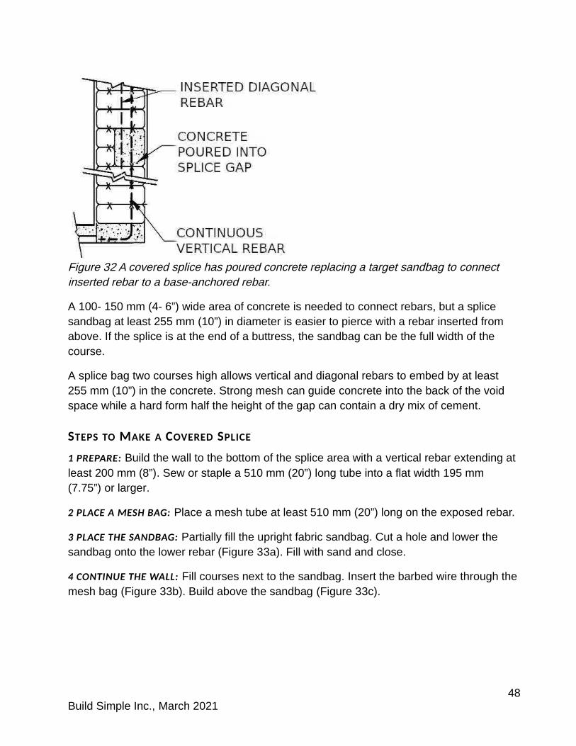
Figure 32 A covered splice has poured concrete replacing a target sandbag to connect inserted rebar to a base-anchored rebar.
A 100- 150 mm (4- 6”) wide area of concrete is needed to connect rebars, but a splice sandbag at least 255 mm (10”) in diameter is easier to pierce with a rebar inserted from above. If the splice is at the end of a buttress, the sandbag can be the full width of the course.
A splice bag two courses high allows vertical and diagonal rebars to embed by at least 255 mm (10”) in the concrete. Strong mesh can guide concrete into the back of the void space while a hard form half the height of the gap can contain a dry mix of cement.
STEPS TO MAKE A COVERED SPLICE
1 PREPARE: Build the wall to the bottom of the splice area with a vertical rebar extending at least 200 mm (8”). Sew or staple a 510 mm (20”) long tube into a flat width 195 mm (7.75”) or larger.
2 PLACE A MESH BAG: Place a mesh tube at least 510 mm (20”) long on the exposed rebar.
3 PLACE THE SANDBAG: Partially fill the upright fabric sandbag. Cut a hole and lower the sandbag onto the lower rebar (Figure 33a). Fill with sand and close.
4 CONTINUE THE WALL: Fill courses next to the sandbag. Insert the barbed wire through themesh bag (Figure 33b). Build above the sandbag (Figure 33c).
48Build Simple Inc., March 2021

Figure 33 A target sandbag for a covered splice (left to right): a- inserted over the rebar into a mesh tube; b- courses next to the sandbag; c- courses added to final wall height.
5 INSERT THE UPPER REBAR down through the center of the wall thickness deep enough to pierce the sandbag. Let the wall dry for one to two days.
6 PREPARE THE SPLICE GAP: Cut the sandbag, remove sand and fabric. Bend all exposed barbed wire into the gap space (Figure 34a). Tack the form in place.
7 ADD CONCRETE TO THE SPLICE: Pour concrete into the mesh bag. Squeeze to place the concrete around the upper parts of the rebar (Figure 34b). Trim excess mesh and remove the form (Figure 34c). After drying, fill gaps with nook plaster to level the surface.
Figure 34 Making the splice (left to right): a- Remove sandbag fabric, b- Place form and use mesh to fill the top, c- Concrete splice with mesh trimmed.
49Build Simple Inc., March 2021

TRUSSED BUTTRESSES
Stiffly anchored reinforcement in a triangular shape provides bracing stronger than rectangular connections. A truss in a buttress stiffly connects the horizontal bond beam rebar to the vertical buttress rebar and the diagonal inserted rebar (note the gray triangle in Figure 35). Trussed buttresses located at corners increase overall building strength.
Figure 35 Diagonal rebars inserted through target sandbags make trusses when spliced.
The barbed wire on the top course may conflict with the rebar location. Build the top course, then insert the diagonal truss rebar before laying barbed wire on the course. Inserttruss rebars carefully using guide poles. Or attach an obvious tag to the outside of the wallso the worker can aim the rebar accurately at the target.
After the diagonal is in the wall, bend the top down into a hook that fits within the poured concrete bond beam. Finish the covered splice to connect the rebars.
The target sandbag must be at the correct height for the planned diagonal (Figure 36). The length of the diagonal determines the height of the target sandbag and the insertion point. These dimensions use a 60 degree angle:
50Build Simple Inc., March 2021

DIAGONAL REBAR LENGTH DISTANCE WALL TOP TO DISTANCE FROM CORNER
BOTTOM OF TARGET SANDBAG TO INSERTION POINT
1,5 m (5’) 1,2 m (4’) 660 mm (26”)
1,8 m (6’) 1,37 m (54”) 760 mm (30”)
2,1 m (7’) 1,5 m (5’) 860 mm (34”)
Figure 36: Choose lengths of trussed diagonals to end in a covered splice.
The vertical at the end of the buttress does not have to be a continuous full-height rebar. Instead it can be spliced to reduce tube cutting. Use a shorter base-anchored rebar at the buttress end. On the course above the target sandbag, insert an upper length of vertical rebar through the sandbag that is long enough to have a hook in the bond beam.
51Build Simple Inc., March 2021
9 WALL OPENINGS FOR MODERATE TO HIGH RISK
Courses above openings can be poorly integrated into wall material, and forces from along an entire length of building wall are concentrated between openings. If possible unite the lintel into the bond beam and use a lighter wall panel or transom above the top ofthe door or window.
Spaced lap rebars may be used for additional wall stiffening between openings. Aligned verticals that are less than 1 m from the nearest continuous base-anchored rebar do not need a shorter lap rebar, since the continuous rebar nearby provides the same function.
One optional wall opening detail is not necessary for high strength resilient CE, but may be very helpful for buildings in the higher seismic risk areas and/ or where engineering design is required. In buildings with many evenly spaced openings, builders who can use welded steel tube door and window frames may reduce wall deformation and/ or receive easier code approval (see section 11, pp. 61- 62).
LINTELS
Lintel size and strength should relate to the span length and weight of wall above the opening and extend 300 mm (12”) or more each side of an opening.
Wood lintels are needed for upward pins. Lintels narrower than 255 mm (10”) should be placed on a 250 x 50 mm (2 x 10) bearing plate on the wall top to spread the weight carried by the lintel out across more of the wall thickness.
Lintels can be sized according to New Zealand guidelines if earthen walls extend 1 m (39”) above the lintel:
WIDTH OF OPENING SIZE OF WOOD LINTEL TYPE OF LINTEL
<900 mm (35”) 100 x 300 mm (4 x 12) laid flat single piece of wood
three 100 x 100 mm (4 x 4) built-up
<1,5 m (5’) 150 x 300 mm (6 x 12) laid flat single piece of wood
three 150 x 100 mm (4 x 6) built-up
Use standard guidelines for reinforced concrete or wood lintels in masonry walls when earthbag walls have fewer courses above openings.
52Build Simple Inc., March 2021
CONNECT LINTELS TO WALLS NEXT TO OPENINGS
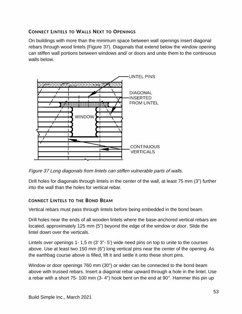
On buildings with more than the minimum space between wall openings insert diagonal rebars through wood lintels (Figure 37). Diagonals that extend below the window opening can stiffen wall portions between windows and/ or doors and unite them to the continuous walls below.
Figure 37 Long diagonals from lintels can stiffen vulnerable parts of walls.
Drill holes for diagonals through lintels in the center of the wall, at least 75 mm (3”) further into the wall than the holes for vertical rebar.
CONNECT LINTELS TO THE BOND BEAM
Vertical rebars must pass through lintels before being embedded in the bond beam.
Drill holes near the ends of all wooden lintels where the base-anchored vertical rebars are located, approximately 125 mm (5”) beyond the edge of the window or door. Slide the lintel down over the verticals.
Lintels over openings 1- 1,5 m (3’ 3”- 5’) wide need pins on top to unite to the courses above. Use at least two 150 mm (6”) long vertical pins near the center of the opening. As the earthbag course above is filled, lift it and settle it onto these short pins.
Window or door openings 760 mm (30”) or wider can be connected to the bond beam above with trussed rebars. Insert a diagonal rebar upward through a hole in the lintel. Use a rebar with a short 75- 100 mm (3- 4") hook bent on the end at 90°. Hammer this pin up
53Build Simple Inc., March 2021
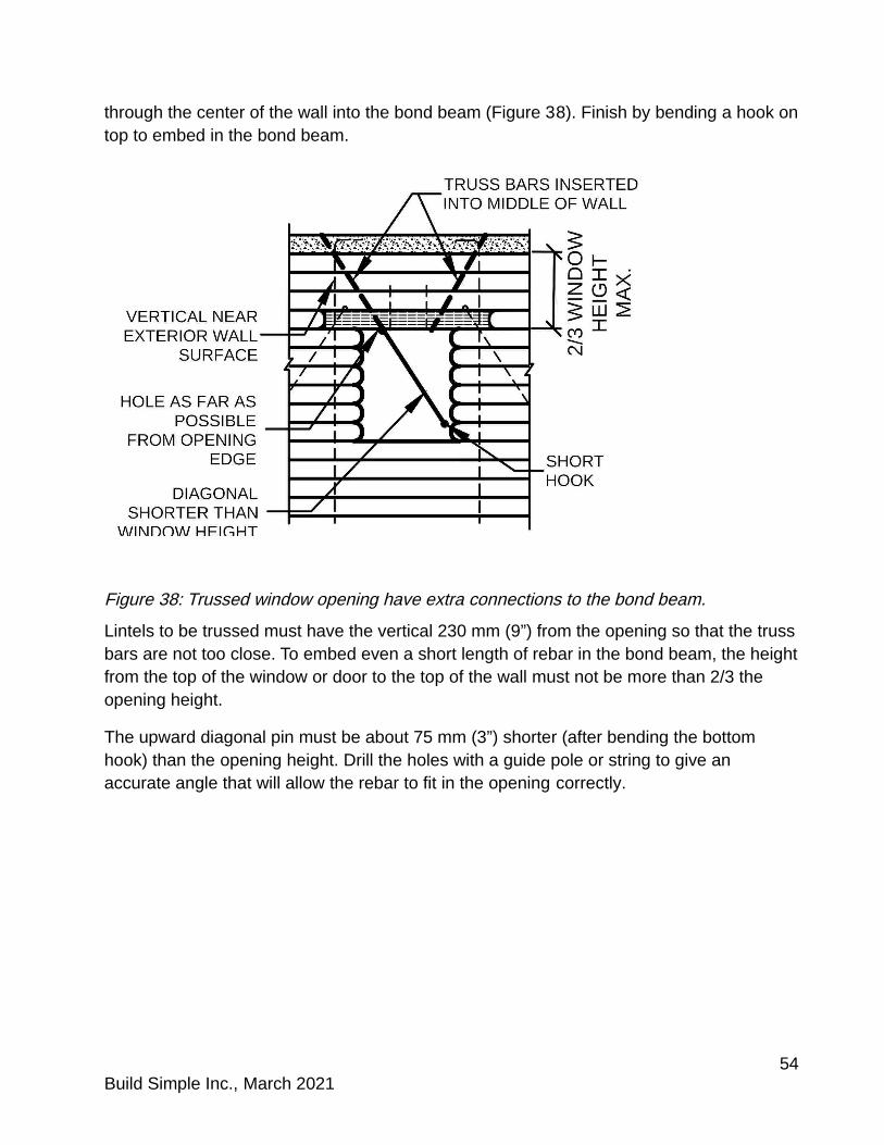
through the center of the wall into the bond beam (Figure 38). Finish by bending a hook ontop to embed in the bond beam.
Figure 38: Trussed window opening have extra connections to the bond beam.
Lintels to be trussed must have the vertical 230 mm (9”) from the opening so that the trussbars are not too close. To embed even a short length of rebar in the bond beam, the heightfrom the top of the window or door to the top of the wall must not be more than 2/3 the opening height.
The upward diagonal pin must be about 75 mm (3”) shorter (after bending the bottom hook) than the opening height. Drill the holes with a guide pole or string to give an accurate angle that will allow the rebar to fit in the opening correctly.
54Build Simple Inc., March 2021
10 BOND BEAMS FOR MODERATE TO HIGH RISK
The bond beam must have enough steel for the weight of the wall and roof or loft. Consider the wall thickness and height, the type of roof and/ or loft and the distance between bracing lines when choosing reinforcement.
Connections to the wall and to the roof above must be stronger than many builders expectbecause earthquakes exert the highest forces in buildings at wall tops. Check with local engineers before using traditional construction. In areas subject to strong winds use special types of attachments for roof framing that are embedded in the bond beam.
Because plaster is an important part of the reinforcing system of resilient CE earthbag, attach the plaster mesh strongly at the wall top. Embed all mesh in concrete bond beams.
The bond beam concrete must embed tops of all pins as well as bent tops of vertical rebar255 mm (10”) or more long. Insert steel so hooks are contained within the depth and widthof the bond beam.
Guidelines in New Zealand recommend bond beams 75% as wide as the wall. Earthbag courses built 125 mm (5”) high have a flat top surface 67% the width of the completed wall. Builders can side tamp the top course of a resilient CE wall within 24 hours of building to flatten the curved outer surface and allow a slightly wider bond beam to rest on the wall top if desired. When side tamping, use a mallet or piece of timber and have at least one person stand on the course to reduce shaking.
Insert diagonal pins joining wall tops with bond beams while wall material is damp. Space pins that extend 600 mm (24”) deep into the wall 600 mm (24”) apart on average at alternating angles. Conventional earthbag relies on the alternating angles of these pins to hold the bond beam to the wall. Because resilient CE relies on bolts or strong hooks on the continuous vertical rebar, angled pins are not the only connection to bond beams but may provide wall stiffening as well as fine grained connection between bond beam and wall.
REINFORCED CONCRETE BOND BEAMS
In high seismic risk areas these construction techniques for resilient CE earthbag should be used with a reinforced concrete bond beam.
New Zealand’s earth building guidelines can be adapted to resilient CE earthbag with the consideration that CE is tougher and flexes more than adobe or rammed earth. In its standard width CE is also 9% wider (and heavier) than the earthen walls specified for NewZealand.
55Build Simple Inc., March 2021
Bracing distances 90% of the New Zealand recommendations for adobe or rammed earth with a conventional light roof are:
BOND BEAM SIZE REBAR SIZE MAX. BRACING DISTANCE
285 x 150 mm (6” x 11.2”) Two D16 (5/8 inch) 3,8 m (12’- 6”)
285 x 175 mm (7” x 11.2”) Two D20 (0.9 inch) 5,1 m (16’- 9”)
For buildings with a heavy roof the bracing distances for the same size bond beams are reduced to 3,2 m (10’- 6”) or 4,6 m (15’- 1”) respectively.
STEEL TUBE BOND BEAMS
Strong steel tube can be welded to form an integral bond beam and ceiling or loft diaphragm, but must be located where both vertical rebar and also angled pins can be welded or bolted to it.
Because a steel tube bond beam will not cover 2/3 of the wall top, use strong strapping every foot from under the top two courses to integrate the bond beam to the upper courses. Stronger soil fill is recommended for the top course under a steel bond beam than that used in the walls.
56Build Simple Inc., March 2021

11 OPTIONAL CONSTRUCTION DETAILS
Careful detailing can increase strength sometimes without increasing cost significantly. The following construction techniques can be used with high strength detailing.
STRONGER FILL INCLUSION
The compressive strength of dried soil fill determines how well wall masses resist cracking. Test walls built of stronger soil fill showed exceptional toughness by bending andtwisting under force but recovering after force removal.
Extra strength can be added to specific parts of walls where stresses concentrate, usually by adding some extra strong clay into the fill mix. Smooth textured soils may also benefit from the addition of a small proportion of sharp sand.
Areas that will benefit from higher strength fill:
the lowest course of building walls, especially within 460 mm (18”) of openings or corners
upper half of walls within 300 mm (12”) of corner rebar upper half of walls within 300 mm (12”) of wall intersections truss-reinforced buttresses
SPLICES
Builders may choose to use open splices in some locations to connect diagonal inserted rebars together or to verticals. Verticals that extend upward can also be connected.
Using two downward diagonals with a vertical creates a fork that will resist uplift by the weight bearing on the diagonal rebars as well as the bond strength between the steel and the dried soil fill. Use vertical strapping where fork diagonals extend into gravel bag courses. This can be an alternative to improve rebar resistance against uplift for areas where a concrete footing is not needed.
OPEN SPLICES
Build tubes to the edge of the splice area. Leave an exposed gap large enough to include the hooks of the rebars. Hammer pre-bent rebars into the gap area, and turn hooks perpendicular to the direction of the wall (Figure 40a).
If upper rebars are used, brace them by tying to an inserted pin or inserting into two courses beneath the open splice.
Pour concrete into the tube end to connect all the rebar hooks (Figure 40b). Shake the concrete down into the tube well and tuck the end under (Figure 40c).
57Build Simple Inc., March 2021

Figure 40: Splice on current course using tube as concrete form (left to right): a- Insert diagonal; b- Insert vertical; c- Both hooks fit within tube form on wall top.
Lay barbed wire on the course immediately to connect to the splice. Delay building above the splice until after the concrete is firm enough to survive tamping forces from above.
PLAIN CORNERS
Some external wall corners may not need two buttresses. Different conditions will require different locations for the vertical rebars.
CORNERS WITH INTERIOR REBARS
Wall corners in the center of buildings (such as at nooks) do not need buttresses. With no buttress, vertical rebars located near the exterior corner leave cut-bag tube containers somewhat exposed to mechanical damage. Locate vertical rebars for minor external corners in an enlarged section of the concrete strip footing so that the rebar is 125 mm (5”) from both interior wall surfaces (Figure 41).
Figure 41 Enlarge strip footings at corners without buttresses, for interior rebar locations.
58Build Simple Inc., March 2021

Make the enlarged footing large enough for the hook.
When building wall above a plain corner, bend the inner barbed wire strand sharply around the vertical rebar at the corner and tie the external strand of wire out the corner.
TRUSSED CORNERS WITH HALF-PIERS
Builders can use trussing on corners without buttresses where seismic risk is moderate or for a small building that has enough bracing within the walls alone. Piers half the story height at a corner provide some compact mass to make walls more stable.
To protect cut-tube containers at a vertical corner rebar without a buttress from mechanicaldamage, use a partial height corner pier just below the splice (Figure 42).
Figure 42 Half height corner piers combined with a trussed wall.
Piers are short sections of wall built twice as wide as normal. Always alternate tube directions and run barbed wire on each course to unite the pier to adjacent walls. Pier length must be a multiple of the wall width (Figure 43a).
This detail allows a plain corner (with no buttresses) to be trussed. Because a trussed rebar is inserted into a covered splice, the vertical rebar must be placed near the exterior corner. A target bag cannot be located at the interior side of a corner where there will be little or no access to the splice void.
At a corner pier locate the corner vertical rebar 125 mm (5”) in from both external edges ofthe walls. Tie barbed wire at all outer corners. Use an inserted lap rebar near the outer corner of the pier (Figure 43b) for extra strength.
59Build Simple Inc., March 2021

Figure 43 Corner pier (left to right): a- Alternate directions of tubes and tube cuts; b- Unite pier to wall corner with interior strand of wire while exterior strand runs continuous.
TRUSSED CORNERS WITH ONE BUTTRESS
If only one buttress is needed at a corner, locate the corner vertical rebar 125 mm (5”) from one exterior wall surface at the inside of the corner made by the buttress (Figure 44).Cuts to the container fabric will be protected by the adjacent tubes, but no wire will be bentaround the rebar. Tie the barbed wire out the corner.
Figure 44 For a single buttress at an external corner locate vertical rebar near the externalbarbed wire strand but near the corner formed byt the buttress.
A single buttress can be trussed. Insert the diagonal truss rebar down from the wall cornerinto a covered splice in the buttress end.
60Build Simple Inc., March 2021
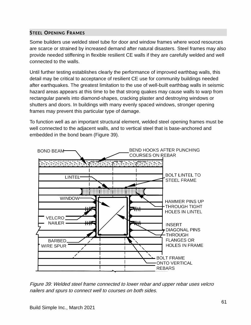
STEEL OPENING FRAMES
Some builders use welded steel tube for door and window frames where wood resources are scarce or strained by increased demand after natural disasters. Steel frames may alsoprovide needed stiffening in flexible resilient CE walls if they are carefully welded and well connected to the walls.
Until further testing establishes clearly the performance of improved earthbag walls, this detail may be critical to acceptance of resilient CE use for community buildings needed after earthquakes. The greatest limitation to the use of well-built earthbag walls in seismic hazard areas appears at this time to be that strong quakes may cause walls to warp from rectangular panels into diamond-shapes, cracking plaster and destroying windows or shutters and doors. In buildings with many evenly spaced windows, stronger opening frames may prevent this particular type of damage.
To function well as an important structural element, welded steel opening frames must be well connected to the adjacent walls, and to vertical steel that is base-anchored and embedded in the bond beam (Figure 39).
Figure 39: Welded steel frame connected to lower rebar and upper rebar uses velcro nailers and spurs to connect well to courses on both sides.
61Build Simple Inc., March 2021

Weld vertical bolts extending above the frame to attach the lintel. Add horizontal rebar spurs about 180 mm (7”) long every 255- 300 mm (10- 12”) in height on both sides of the frame so that barbed wire on every other course can be attached to the frame (Figure 39).
Fasten the frame onto base-anchored verticals topped with bolts. Build the wall around theframe. At courses with a spur, run the course barbed wire up to the spur, wrap around one side and then the other, then return wire back into the wall. Every other course place a velcro nailer between the courses that buts up to the frame. Screw or nail the frame securely to the nailer.
Add diagonal pins at a 45º angle to either side near the bottom, through holes drilled into the frame.
Attach the lintel and/ or frame to the bond beam using vertical rebars. Rebars near the ends of the lintel must be inserted through holes before building the courses above, which use cut-bag and punched-bag technique. Rebars near the center of the opening can be inserted up into the wall above the opening after the earthen wall is completed. All of theseverticals must have hooks bent on top after the earthen wall is completed.
62Build Simple Inc., March 2021
12 ABBREVIATIONS AND DEFINITIONS
Buttress: A stub wall added perpendicular to a building wall to brace it. Often used on exterior walls, especially at corners or wall intersections
CE: Contained earth (earthbag built with damp cohesive soil fill) in bags or tubes
CG: Contained gravel a.k.a. gravel bag (water-resistant earthbag filled with gravel) in bags or short tubes
CS: Contained sand (low strength earthbag with loose fill or dry fill) in bags
Covered splice: Section of concrete to connect lower rebars to an upper rebar in a void space below current course.
FDN: Foundation
Fork: Multiple lower diagonal inserted rebars spliced to an upper rebar.
FTG: Footing
Spaced lap: When separate rebars are inserted one directly over the other and a shorter lap rebar overlaps them both.
LVL: Level
MAX: Maximum
MIN: Minimum
Open splice: Section of concrete to connect lower rebars together or an upper rebar to lower rebars. Concrete is poured below building above the splice level.
O.C.: On center (similar to at __ centres)
Pier: An area of thickened wall. This can be a repeating identical element where a wall is thickened for bracing purposes
Stub: A short wall with only one end attached to another wall that lacks bracing
TYP: Typical indicates that every where this element appears in the detail or plan itis the same
63Build Simple Inc., March 2021