high speed transmission over mmf and pf-pof using mimo ... · two mmf detection points ¾two...
TRANSCRIPT
Lehrstuhl fürNachrichten- und Übertragungstechnik
Technische Fakultät derChristian-Albrechts-Universität zu Kiel
L N T
S.Schöllmann, 9.1.07
1
Stefan Schöllmann
High Speed Transmission over MMF and PF-POF using MIMO
Approach

Lehrstuhl fürNachrichten- und Übertragungstechnik
Technische Fakultät derChristian-Albrechts-Universität zu Kiel
L N T
S.Schöllmann, 9.1.07
2
Motivation
Initial Point: High speed transmission over short distances (< 300m)
Easier handling compared to SMF
Multi Mode Fibre & Plastic Optical Fibre
• Bending
• Connectors
• Cheaper components
Short reach at high speed
• Low bandwidth distance product
• Coarse (C)WDM
• Equalization
• Mode Group Diversity Multiplexing
Research Topic: Increase of bandwidth distance product
Existing Alternative

Lehrstuhl fürNachrichten- und Übertragungstechnik
Technische Fakultät derChristian-Albrechts-Universität zu Kiel
L N T
S.Schöllmann, 9.1.07
3
Outline
• Motivation
• Introduction
– Multi Mode Fibre (MMF) and Plastic Optical Fibre (POF)
– Optical Multi Input Multi Output (MIMO) system
• Experimental Investigations
– Intensity distributions for different launching positions
– Mode dispersion
– Crosstalk
– Equalization
• Conclusion and outlook

Lehrstuhl fürNachrichten- und Übertragungstechnik
Technische Fakultät derChristian-Albrechts-Universität zu Kiel
L N T
S.Schöllmann, 9.1.07
4
Introduction (1)
• Large core diameter
(MMF:50 – 62,5 μm; POF: 62,5 -1000 μm)
• Multi mode character
• Mode dispersion
• Mode coupling
1
0( ) ( )
M
m mm
h t P tδ τ−
== −∑
MMF and POF
M = Number of excited mode groupsPm = Power of mode group m
r
Signal 1
Sign
al 2
Signal 3
Impulse Response
τm = Time delay of mode group m
With the effect of mode coupling
,
1
0m n m
N
nn
P Pγ−
== ⋅∑

Lehrstuhl fürNachrichten- und Übertragungstechnik
Technische Fakultät derChristian-Albrechts-Universität zu Kiel
L N T
S.Schöllmann, 9.1.07
5
Assignment of different
signals to different mode groups
Separation of different
mode groups
Introduction (2)
Principle of Mode Group Diversity Multiplexing as MIMO approachTransmitter Receiver
high order modes
low order modes
Multiplexing De-Multiplexing
rest
ricte
d la
unch
ing
spot
s
core
OLP
CLP
Intensity [a.u.]
Radius [um]
0
Power distribution in MMF/POF
CLP OLP
Lehrstuhl fürNachrichten- und Übertragungstechnik
Technische Fakultät derChristian-Albrechts-Universität zu Kiel
L N T
S.Schöllmann, 9.1.07
6
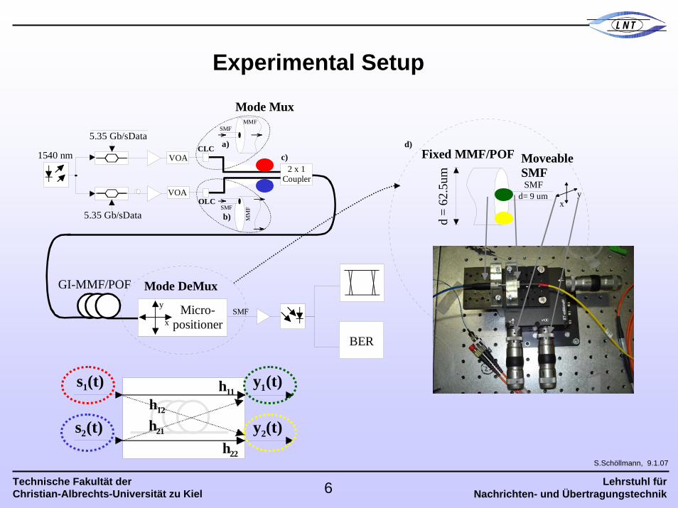
Experimental Setup
VOA
VOA
GI-MMF/POF
Mode Mux
Mode DeMux
SMFMMF
OLP
a)
SMF
MM
F
b)
c)1540 nm
5.35 Gb/sData
CLP
CLC
OLC
2 x 1Coupler
Micro-positionerx
y
BER
SMF
xy
SMF
d)Fixed MMF/POF Moveable
SMF
d =
62.5
um
d= 9 um
5.35 Gb/sData
s1(t)
s2(t)
y1(t)
y2(t)
h11
h21
h12
h22

Lehrstuhl fürNachrichten- und Übertragungstechnik
Technische Fakultät derChristian-Albrechts-Universität zu Kiel
L N T
S.Schöllmann, 9.1.07
7
Intensity distributions for different launching positions on MMF
Experimental Results (1)
-10
-20
-30
-40
-50
60 μm
60 μm
[dBm]
Centre Launch Position
Concentration of power
in the centre of the core
Offset Launch Position
Power is distributed over complete core radius (closer to core cladding)
-10
-20
-30
-40
-50
60 μm
60 μm
[dBm]
CLP OLP 20 um

Lehrstuhl fürNachrichten- und Übertragungstechnik
Technische Fakultät derChristian-Albrechts-Universität zu Kiel
L N T
S.Schöllmann, 9.1.07
8
Intensity distribution after 300 m GI-MMF
Experimental Results (2)
OLP, 20 umCLP, 0 um
-10
-20
-30
-40
-50
-60
[dBm]-25
-30
-40
-50
-60
[dBm]
60um
60um
60um60
um
No significant change for intensity distributions at CLP and OLP

Lehrstuhl fürNachrichten- und Übertragungstechnik
Technische Fakultät derChristian-Albrechts-Universität zu Kiel
L N T
S.Schöllmann, 9.1.07
9
Demultiplexing of the signals (MMF)
Experimental Results (3)
Completely distorted eye based on mode dispersion
No error free transmission reduction of mode dispersion,
3020100-10-20-30
30
20
10
0
-10
-20
-30
boun
dary
e) area 1
area 2
200 ps
200 ps
f)
g)
2 x 5.35 Gb/s with MGDM
Overfilledlaunch
position
MM
F's c
ore
Transmitter Receiver
Completedetection
area
MM
F's c
ore
1 x 10.7 Gb/s
500ps
Wide open eyes error free transmission is possible
Reduced influence of mode dispersion
Widened one level higher influence of crosstalk

Lehrstuhl fürNachrichten- und Übertragungstechnik
Technische Fakultät derChristian-Albrechts-Universität zu Kiel
L N T
S.Schöllmann, 9.1.07
10
Experimental Results (4)
10-1
10-12
10-10
10-8
10-6
10-4
10-2
-34 -32 -30 -28 -26 -24 -22
BER
Received input power [dBm]
Detection Area 2
Detection Area 1
only s2(t) transmittedonly s1(t) transmitted
6 dB
10-1
10-12
10-10
10-8
10-6
10-4
10-2
BER
-32 -30 -28 -26 -24
ΔPdB=(P2 -P1)dB
ΔP=0dB
ΔP=3
ΔP=6dB
ΔP=9dB
Only detection Area 2for varying ΔP
both, s1(t) & s2(t)transmitted
300m GI-MMF 300m GI-MMF
Received input power [dBm]
Strong mode coupling from low order modes to high order modes for equal power levels
Equalization
Significant reduction for increasing ΔP = P2-P1
Performance analysis: MGDM with different power levels for s1(t) and s2(t)
Unequal power levelsEqual power levels

Lehrstuhl fürNachrichten- und Übertragungstechnik
Technische Fakultät derChristian-Albrechts-Universität zu Kiel
L N T
S.Schöllmann, 9.1.07
11
Intensity distributions after 10m GI-POF
Experimental Results (5)
CLP
No significant change in intensity distributions for CLP and OLP
-10
-20
-30
-40
-50
100 μm
100 μ m
[dBm]
-10
-20
-30
-40
-50
100 μm
100 μm
[dBm]
OLP, 20 um

Lehrstuhl fürNachrichten- und Übertragungstechnik
Technische Fakultät derChristian-Albrechts-Universität zu Kiel
L N T
S.Schöllmann, 9.1.07
12
Restricted detection point 1
200 ps
Demultiplexing of the signals (POF)
Experimental Results (6)
Wide open eye for CDP
low influence of mode dispersion
low interference from second channel
Restricted detection point 9
200 ps
ODPWide open eye for ODP
more distorted due to
Mode dispersion
High crosstalk from second signal
CDP
Lehrstuhl fürNachrichten- und Übertragungstechnik
Technische Fakultät derChristian-Albrechts-Universität zu Kiel
L N T
S.Schöllmann, 9.1.07
13
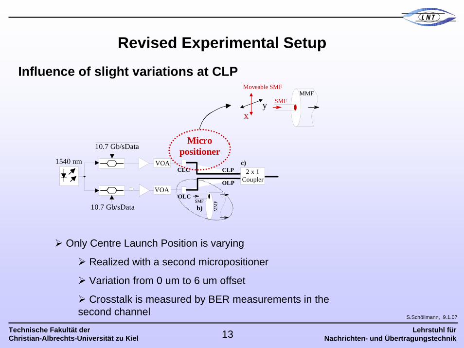
Influence of slight variations at CLP
Revised Experimental Setup
10.7 Gb/sData
VOA
VOA
SMFMMF
OLP
SMF
MM
Fb)
c)1540 nm
10.7 Gb/sData
CLPCLC
OLC
2 x 1Coupler
xy
Micropositioner
Moveable SMF
Only Centre Launch Position is varying
Realized with a second micropositioner
Variation from 0 um to 6 um offset
Crosstalk is measured by BER measurements in the second channel

Lehrstuhl fürNachrichten- und Übertragungstechnik
Technische Fakultät derChristian-Albrechts-Universität zu Kiel
L N T
S.Schöllmann, 9.1.07
14
Influence of slight variations at CLP
Experimental Results (7)
0 um to 3 um offset
no significant performance change
4 um and 5 um offset
significant performance reduction to a BER of 10-4
6 um offset
BER of 3*10-3 Correction by standard FEC is not possible
Equalization
10-1
10-12
10-10
10-8
10-6
10-4
10-2
0 1 2 3 4 5 6
BER
offset [um]
10 m GI-POF
Lehrstuhl fürNachrichten- und Übertragungstechnik
Technische Fakultät derChristian-Albrechts-Universität zu Kiel
L N T
S.Schöllmann, 9.1.07
15
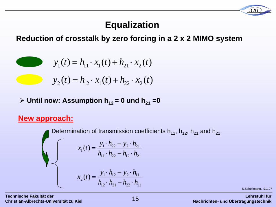
Equalization
Until now: Assumption h = 0 und h =012 21
Reduction of crosstalk by zero forcing in a 2 x 2 MIMO system
1 11 1 21 2( ) ( ) ( )y t h x t h x t= ⋅ + ⋅
2 12 1 22 2( ) ( ) ( )y t h x t h x t= ⋅ + ⋅
New approach:Determination of transmission coefficients h11, h12, h21 and h22
1 12 2 112
12 21 22 11
( ) y h y hx th h h h
⋅ − ⋅=
⋅ − ⋅
1 22 2 211
11 22 12 21
( ) y h y hx th h h h
⋅ − ⋅=
⋅ − ⋅

Lehrstuhl fürNachrichten- und Übertragungstechnik
Technische Fakultät derChristian-Albrechts-Universität zu Kiel
L N T
S.Schöllmann, 9.1.07
16
Experimental Equalization Setup
Two MMF detection points
Two detection points with different power influence of the signals (Distance:10 um)
Determination of the transmission coefficients (h11, h12, h21, h22)
Sampling the bit sequences with the oscilloscope at both points (y1 and y2)
Offline equalization
10 Gb/sData
VOA
VOA
GI-POF
Mode MuxSMF
MMF
OLP
a)
SMFM
MF
b)
c)1540 nm10m
10 Gb/sData
CLP
CLC
OLC
2 x 1Coupler
Mode DeMux
x
MMF
Fixed MMFMoveableMMF
d)
Fibre 1: 62.5 um
y
MMFDetektor Sampling the bit
sequence with 4050points

Lehrstuhl fürNachrichten- und Übertragungstechnik
Technische Fakultät derChristian-Albrechts-Universität zu Kiel
L N T
S.Schöllmann, 9.1.07
17
Experimental Results (8)
Both eye diagrams show four different power levels (00, 01, 10 11)
Completely distorted eye due to crosstalk
Two MMF detection points
Detection point 2Detection Point 1
0 0
0 11 0
1 1
s1 s2

Lehrstuhl fürNachrichten- und Übertragungstechnik
Technische Fakultät derChristian-Albrechts-Universität zu Kiel
L N T
S.Schöllmann, 9.1.07
18
Experimental Results (9)
Determination of the transmission coefficients by detecting only one signal
Only power influence is measured
Determination of transmission coefficients
Detection point 1 Influence of signal 1
Influence of signal 2
h11
h21
Lehrstuhl fürNachrichten- und Übertragungstechnik
Technische Fakultät derChristian-Albrechts-Universität zu Kiel
L N T
S.Schöllmann, 9.1.07
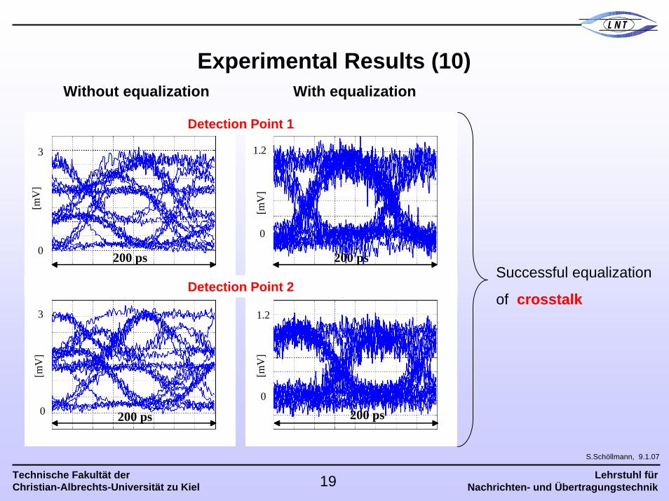
19
Without equalization
200 ps 200 ps
200 ps 200 ps0
0
3
3
[mV
][m
V]
[mV
][m
V]
0
0
1.2
1.2
With equalization
Successful equalization
of crosstalk
Detection Point 1
Detection Point 2
Experimental Results (10)

Lehrstuhl fürNachrichten- und Übertragungstechnik
Technische Fakultät derChristian-Albrechts-Universität zu Kiel
L N T
S.Schöllmann, 9.1.07
20
Conclusion & Outlook
Experimental investigations of MIMO approach using MMF/POF
Experimental realization of a 2 x 2 MIMO setup based on MGDM
Reduction of the mode dispersion influence
Investigation of crosstalk between the channels
Dependant on the power levels in the channels
Dependant on the exact launching positions
Successful equalization of crosstalk by zero forcing method
Investigation of modal noise in optical MIMO systems