high-speed real-time digital emulation for hardware-in-the-loop
TRANSCRIPT

High-Speed Real-Time Digital Emulation forHardware-in-the-Loop Testing of Power Electronics:
A New Paradigm in the Field of Electronic DesignAutomation (EDA) for Power Electronics Systems
The MIT Faculty has made this article openly available. Please share how this access benefits you. Your story matters.
Citation Kinsy, Michel A., Dusan Majstorovic, Pierre Haessig, JasonPoon, Nikola Celanovic, Ivan Celanovic, and Srinivas Devadas."High-Speed Real-Time Digital Emulation for Hardware-in-the-Loop Testing of Power Electronics: A New Paradigm in the Fieldof Electronic Design Automation (EDA) for Power ElectronicsSystems." International Exhibition and Conference for PowerElectronics, Intelligent Motion and Power Quality 2011 (PCIM Europe2011), May 17-19, 2011, Nuremberg, Germany.
As Published http://toc.proceedings.com/12357webtoc.pdf
Publisher Mesago PCIM GmbH
Version Author's final manuscript
Citable link http://hdl.handle.net/1721.1/87082
Terms of Use Creative Commons Attribution-Noncommercial-Share Alike

Detailed Terms http://creativecommons.org/licenses/by-nc-sa/4.0/

High-Speed Real-Time Digital Emulation for Hardware-in-the-LoopTesting of Power Electronics: A New Paradigm in the Field of
Electronic Design Automation (EDA) for Power Electronics Systems
Michel A. Kinsy, Dusan Majstorovic, Pierre Haessig, Jason Poon, Nikola Celanovic,Ivan Celanovic, and Srinivas Devadas
Massachusetts Institute of Technology, Cambridge, USA. [email protected]
Abstract
This paper details the design and application of a new ultra-high speed real-time simulationfor Hardware-in-the-Loop (HiL) testing and design of high-power power electronics systems.Our real-time hardware emulation for HiL system is based on a custom, heterogeneous, recon-figurable, multicore processor design that emulates power electronics, and includes a circuitcompiler that translates graphic system models into processor executable machine code. Wepresent digital processor architecture details, and describe the process of power electronic cir-cuit compilation. This approach to real-time emulation yields real-time execution in the order of1µs simulation time step (including input/output latency) for a broad class of power electronicsconverters. In addition, we present HiL simulation experimental results for three representativesystems: namely, a variable speed induction motor drive, a utility grid connected photovoltaicconverter system, and a hybrid electric vehicle motor drive.
1 INTRODUCTION
Power electronics is one of the key technologies enabling wider proliferation of renewable energy gener-ation and realization of the smart grid vision. Power electronics could potentially reduce overall electricityconsumption by more than 30% [1]. In order for power electronics to reach this point, advancementsare needed in the area of Electronic Design Automation (EDA) tools, among others. Design automationcould significantly reduce development cycles, improve reliability, and accelerate the development ofmore complex systems. In particular, we believe that an integrated EDA tool would immensely benefitthe area of control testing and rapid design prototyping.
In this paper, we propose a new software/hardware co-design EDA platform for comprehensive testingand validation of power electronics controller hardware, firmware, and software performance by meansof high-fidelity, real-time emulation of power electronics in Hardware-in-the-Loop (HiL) configuration. InHiL testing configuration, the power electronics converter is replaced by ultra-fast real-time emulationthat interacts with the controller via high-speed physical input/output interfaces. From the controllerpoint of view, the emulation is so seamless that there is no distinction between the real-time control ofthe physical plant and the hardware emulator. The paper is organized in five sections. Section 2 framesthe challenges facing the design automation and testing of power electronics. Section 3 describes theproposed framework for real-time hardware emulation. Section 4 compares the fidelity of the proposedreal-time emulator with the real power electronics system, and presents two more design examples.Section 5 summarizes the paper.
2 DESIGN REQUIREMENTS FOR HiL POWER ELECTRONICS
2.1 Benefits of Hardware Emulation for Power Electronics
Today, power electronics engineers mostly rely on off-line simulations in the early design stage, andon hardware prototypes–low voltage simulators–in the final stages of the design and testing. However,
off-line simulations are generally slow and only provide a certain level of functional faithfulness, espe-cially when modeling embedded controller and its interactions. Hardware emulation in HiL configurationenables more realistic testing while reducing the complexity and cost. The key benefits of the real-timeemulation for HiL testing are: (1) accelerated testing and validation; (2) reduced testing time needed inthe lab; (3) simulation of all operating points and scenarios that are difficult or impossible to recreate witha real system (4) fault injection capability; (5) real-time access to all signals that are difficult to measurein a real system.
2.2 Hardware Emulation: A Known Design Concept in Design Automation
The automotive industry has been using the concept of HiL simulation as a ubiquitous tool for testingthe engine control unit (ECU). Connecting an ECU to a real-time simulator of a car enables exhaustivetesting of ECU. In computer engineering, hardware emulation, or in-circuit emulation, is used to describethe testing of a digital processor design by replacing it with another system (hardware emulator) thatimitates the behavior of the system under test. In power electronics, replacing the power converter, grid,and electromechanical components with a real-time digital emulation takes high-power hardware out ofthe testing environment without any loss of fidelity(from the controller point of view). High-fidelity testingrequires a real-time emulation system with: (1) ultra-low latency and high-speed simulation (∼1µs); (2)ability to simulate switched and nonlinear systems; (3) flexibile modeling; (4) ease of use and variablelevels of abstraction. Most HiL simulators, based on off-the-shelf processors, exhibit large latencies onthe order of 50µs. Yet, power converters operate at switching frequencies of ∼10kHz, thus limiting thefidelity and applicability of HiL platforms based on the standard processors.
3 HiL SYSTEM ARCHITECTURE
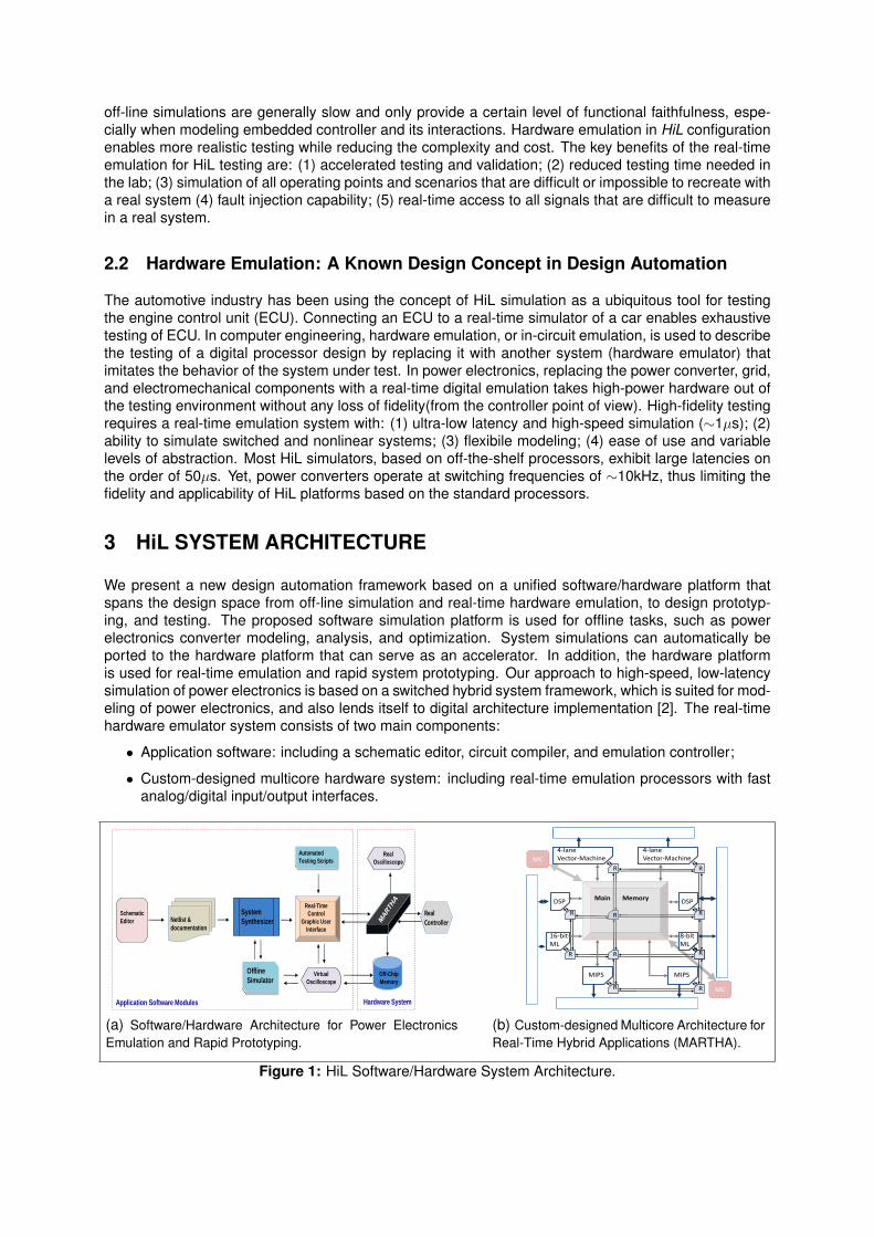
We present a new design automation framework based on a unified software/hardware platform thatspans the design space from off-line simulation and real-time hardware emulation, to design prototyp-ing, and testing. The proposed software simulation platform is used for offline tasks, such as powerelectronics converter modeling, analysis, and optimization. System simulations can automatically beported to the hardware platform that can serve as an accelerator. In addition, the hardware platformis used for real-time emulation and rapid system prototyping. Our approach to high-speed, low-latencysimulation of power electronics is based on a switched hybrid system framework, which is suited for mod-eling of power electronics, and also lends itself to digital architecture implementation [2]. The real-timehardware emulator system consists of two main components:
• Application software: including a schematic editor, circuit compiler, and emulation controller;
• Custom-designed multicore hardware system: including real-time emulation processors with fastanalog/digital input/output interfaces.
Schematic
Editor Netlist &
documentation
System
Synthesizer
Real-Time
Control
Graphic User
Interface
Virtual
Oscilloscope
Application Software Modules
Offline
Simulator
Automated
Testing Scripts Real
Oscilloscope
Off-Chip
Memory
RealController
Hardware System
(a) Software/Hardware Architecture for Power ElectronicsEmulation and Rapid Prototyping.
Main Memory
MC
DSP DSP
16-bit ML
8-bit ML
MIPSMIPS
4-lane Vector-Machine
4-lane Vector-Machine
R
R
R
R
R
R
R R
R
R
MC
I/O
I/O
I/O
I/O
(b) Custom-designed Multicore Architecture forReal-Time Hybrid Applications (MARTHA).
Figure 1: HiL Software/Hardware System Architecture.
3.1 Modeling Approach: Switched Hybrid Automaton
the proposed switched hybrid system approach to power electronics converter modeling relies on piece-wise linear passive elements, piece-wise linear switches, current and voltage sources (both controlledand idependent). The switched hybrid system model is given in the state space form, as:
x(t) = Aqx(t) +Bqu(t) (1)
where x(t) ∈ X ⊂ Rn is the continuous state space vector, Aq ∈ Rn×n; Bq ∈ Rn×m; and u ∈ Rm is theinput vector. Any discrete state of the circuit belongs to a finite set Q = {q1..qn} and further defines thegiven state space representation. Every discrete state therefore has a unique dynamic behavior, thatwe call mode, associated with it that defines the operation of the circuit. In this framework we can alsodefine a mode, denoted mq, where q ∈ Q, is the operation of the system defined by given state spacex(t) = Aqx(t) +Bqu(t) and a given q.
Definition 1 (Switched Hybrid Automaton) A switched hybrid system is a collectionH = (Q,X, f,E,G)where: Q = {q1..qn} is set of discrete states, X ⊆ Rn is the continuous state space; f : Q 7→ (X 7→ Rn)assigns to every discrete state continuous vector field on X; E ⊆ Q × Q is a collection of discretetransitions; G : E 7→ 2X assigns each e = (q, q′) ∈ E a guard.
The state space representation of hybrid automaton modes, as defined in Equation 1, can be discretized.We use the exact discretization method via state-transition matrix. The discretized state space systemmatrices, for a given mode are given as:
x(k + 1) = Ad(q)x(k) +Bd(q)u(k) (2)
y(k) = Cd(q)x(k) +Dd(q)u(k) (3)
g(k) = Cgd(q)x(k) +Dgd(q)u(k) (4)
where k is the discrete time, y is the output vector, g is the guard vector (it is treated as the outputvector). In the discretized form the set of matrices {Ad(q), Bd(q), Cd(q), Dd(q), Cgd(q), Dgd(q)} completelydefines the dynamic behavior of the system.
3.2 Application Software
Application software is the interface for specifying the system that is emulated in hardware. After thesystem is specified in the schematic editor, the circuit compiler analyzes the circuit, and extracts thefull switched hybrid system representation, followed by compilation and linking of the model into theprocessor executable binary file. The simulation controller loads the binary file into the processor andprovides control of the simulation via start/stop commands, etc. and configures the “in-circuit” probing.
Application Software Implementation
The software environment comprises three layers: (1) the power electronics modeling layer, (2) formula-tion and analysis layer, and (3) the synthesis and simulation layer. In the software domain, we focus onabstraction, structure, and modularity. Figure 1(a) shows the software modules and the data flows. Thefirst layer consists of the schematic editor and the circuit netlist abstractor. The Schematic Editor librarycomponents include piece-wise linear circuit elements (e.g. resistors, inductors, capacitors), machinemodels, semiconductor devices (e.g. diodes and IGBTs), independent and controlled sources, con-tactors and predefined power electronics switching blocks(e.g., a three-phase two-level voltage sourceinverter etc.) and control blocks. Given a power electronics circuit, the Netlist Extractor module gen-erates a list of components, values, and connectivity. The hybrid model formulation is done throughthe System Synthesizer module, which generates the set of state space matrices, modes, transitionequations, guards, etc. The synthesizer output files can be used by the offline simulator, or by the real-time controller to be mapped onto the the hardware. The Offline Simulator module uses hybrid modelformulation (both preset and actively user controlled), and outputs via the Virtual Oscilloscope module
time-domain signals. The Real-Time Control Graphic User Interface module allows user to run the modelin real-time on the hardware, and to control the emulation manually or via script.
3.3 Multicore Hardware Architecture
We developed a domain-specific digital processor architecture that consists of two sets of computa-tional elements: high-speed, low-latency, dynamic system state space solver (discretized with fixedtime-step), vector cores, and reduced instruction set computing (RISC) cores that control simulation andinput/output access. The architecture guarantees combined real-time emulation latency and executiontimes of 1µs.
Hardware Implementation
Figure 1(b) shows the macro-view of the architecture. Processing cores are connected via an irregular,two dimensional mesh network of bufferless reconfigurable routers. The number of any class of process-ing cores (e.g., vector-machines, DSPs, RISC cores) is expandable, and the interconnect network isscalable. The architecture uses two techniques to achieve parallelism: namely, Single Program-MultipleData (SPMD), where the two autonomous vector processors can simultaneously execute the same pro-gram on different data sets, and Multiple Program-Multiple Data (MPMD) style approach, where thedifferent processors and micro-processors simultaneously operate on independent programs. The ar-chitecture comprises: two four-lane chained vector-machine cores for fast and parallel matrix computa-tion [3, 4], two RISC cores, two digital signal processors (DSP), a 16-bit programmable microprocessor,an 8-bit programmable microprocessor, a bank style main memory, with no cache for deterministic dataaccess [5], and two memory controllers for off-chip communication.
The performance of the proposed hardware architecture is verified on a Xilinx ML506 FPGA developmentboard, with a custom-designed analog/digital I/O board for the controller under test and user outputs.Our current design roughly uses 90% of the slices and BRAMs on the FPGA, and runs at 200MHz.
4 EXPERIMENTAL RESULTS AND APPLICATION EXAMPLES
To demonstrate the fidelity and the versatility of our full electronic systems design and automation ap-proach, and our integrated software/hardware system solution, we present Hardware-in-the-Loop sim-ulations of three representative systems: namely, a variable speed induction motor drive, a utility gridconnected photovoltaic converter system, and a hybrid electric vehicle motor drive.
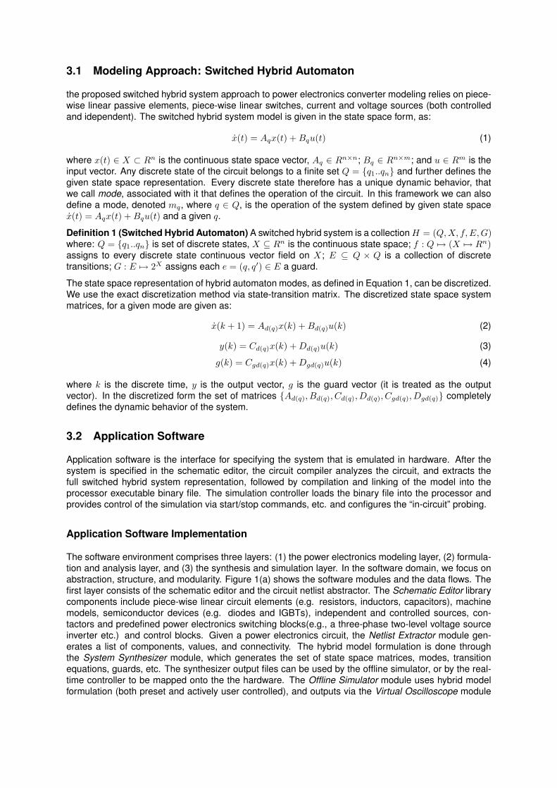
4.1 Variable Speed Induction Motor Drive
The variable speed drive consists of a three-phase voltage source, a three-phase diode bridge rectifier,a DC-link, a three-phase two-level voltage-source inverter, an output filter and an induction machine.
Induction Motor
3 Ph Inverter
Rdc1
L_rect_outA
Lrect a
Lrect c
Lrect b
V V1
Laf
Caf1
Lcf
V Udc
V V2
V V3
Rbf1
Ccf1
V U_rect_out
Cbf1
Rdc
Raf1
Va
Vb
Vc
Cdc
3 Ph Rectifier
AI_inv
Rcf1
Lbf
schematic "08 3P_Rec_2L_Inv_Motor connected2.tse" - 13/03/2011 00:08:33
(a) Schematic diagram of the motor drive model ofa three-phase rectifier, two-level voltage source in-verter, filter and induction machine that is emulatedin real-time in our system.
(b) Experimental measurements of the real-timeemulation system inverter output current, line to linemotor voltage, and stator current, on channels 1, 2,and 3 respectively.
Figure 2: Variable Speed Induction Motor Drive Application Experimental Results.

(1) ACS-150 variable speed drive controller. Device-under-test (DUT)
(3) Variable speed drive converter connected to three-phase induction machine.
(2) HIL platform simulating variable speed drive connected to three-phase
Controller signals(2)
(1)
(3)
Figure 3: Motor-drive experimental setup for parallel physical system and real-time digital emulatortesting.
(a) Experimental measurements of the line-to-linemotor voltage and the motor phase current of thephysical system are shown on channels 2 and 4,and the real-time hardware emulator waveforms areon channels 1 and 3.
1
2
3
1
32 ~1.2ms
Physical system (ACS150) line-to-line voltage response
Digital gate drive signal
Real-time digital emulator line-to-line voltage response
(b) Three-phase inverter line-to-line voltage re-sponse on the physical system, and real time em-ulation system to a gate drive signal.
Figure 4: High-Fidelity Emulation of Variable Speed Induction Motor Drive Application.
To illustrate the fidelity of our real-time digital emulation platform, we run in parallel an industrial gradeopen-loop variable speed drive, ABB ACS-150, and our real-time hardware emulator, both driven fromthe same controller. Figure 2 shows the system comprising three-phase diode rectifier and three-phasetwo-level IGBT inverter. Figure 3 shows the experimental setup, where the same controller is used forboth the real system and the real-time emulated system. Measured waveforms on both the real systemand the emulator are shown in Figure 4(a) with almost one-to-one matching. Emulator response latencyis measured to be less than(1.3µs), as shown in Figure 4(b).
4.2 Utility Grid Connected Photovoltaic Converter System
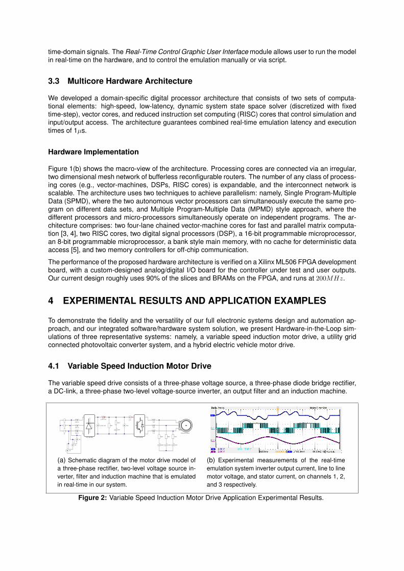
To illustrate, that beyond the real-time high-fidelity, our EDA environment also provides support for mod-eling, design, prototyping, and HiL testing to a wide range of applications, we present another examplesystem: a grid connected photovoltaic converter system.
Figure 5(a) shows a two-stage utility grid connected photovoltaic converter model, that consists of aphotovoltaic panel module, boost converter, a three-level NPC inverter, an input filter, and a grid. Figure5(b) shows voltages Vab and Vbc on channels 1 and 2, respectively.
4.3 Hybrid Electric Vehicle Motor Drive
In recent years, we have witnessed a significant increase in the development efforts focused on hybridand electric vehicle drivetrains. Presenting a safety critical application, these development efforts require
Lb
Lc
La
Rdc2
Rdc1
Rb2
Rb1
Ra
Lp
Rc
Rp
Lb1 Lb2PV panel
AI_c
AI_b
AI_a
Ra2
Ra1
C2
C1
3-level Inverter
Rc1
Rc2
V Vpv
3-level Boost
Cpv
Va
Vb
VcLc2Lc1
CcCb
Rb
La1
AIpv
gnd
Ca
La2
schematic "03 ABB PV 3L Boost Model connected3.tse" - 12/03/2011 23:44:47
(a) Schematic diagram of the PV panel, boost con-verter, three-level voltage source inverter, filter andutility grid.
(b) Experimental measurements of the real timeemulation system waveforms, voltages at the three-level inverter and current at utility grid.
Figure 5: Utility Grid Connected Photovoltaic Converter System Application.
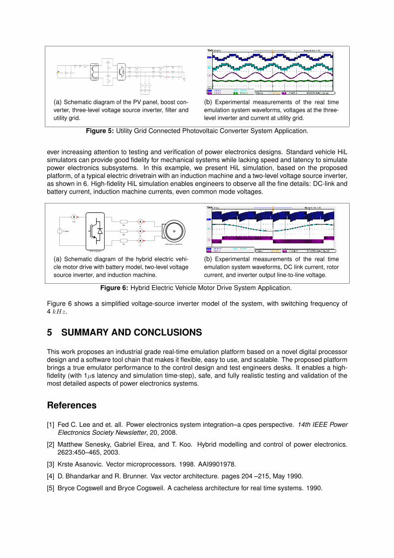
ever increasing attention to testing and verification of power electronics designs. Standard vehicle HiLsimulators can provide good fidelity for mechanical systems while lacking speed and latency to simulatepower electronics subsystems. In this example, we present HiL simulation, based on the proposedplatform, of a typical electric drivetrain with an induction machine and a two-level voltage source inverter,as shown in 6. High-fidelity HiL simulation enables engineers to observe all the fine details: DC-link andbattery current, induction machine currents, even common mode voltages.
3Ph inverter
V batt
AIa
induction machine
Ra
Rb
Rc
AI dc
AIc
AIb
schematic "eCar Model.tse" - 11/03/2011 18:44:52
(a) Schematic diagram of the hybrid electric vehi-cle motor drive with battery model, two-level voltagesource inverter, and induction machine.
(b) Experimental measurements of the real timeemulation system waveforms, DC link current, rotorcurrent, and inverter output line-to-line voltage.
Figure 6: Hybrid Electric Vehicle Motor Drive System Application.
Figure 6 shows a simplified voltage-source inverter model of the system, with switching frequency of4 kHz.
5 SUMMARY AND CONCLUSIONS
This work proposes an industrial grade real-time emulation platform based on a novel digital processordesign and a software tool chain that makes it flexible, easy to use, and scalable. The proposed platformbrings a true emulator performance to the control design and test engineers desks. It enables a high-fidelity (with 1µs latency and simulation time-step), safe, and fully realistic testing and validation of themost detailed aspects of power electronics systems.
References
[1] Fed C. Lee and et. all. Power electronics system integration–a cpes perspective. 14th IEEE PowerElectronics Society Newsletter, 20, 2008.
[2] Matthew Senesky, Gabriel Eirea, and T. Koo. Hybrid modelling and control of power electronics.2623:450–465, 2003.
[3] Krste Asanovic. Vector microprocessors. 1998. AAI9901978.
[4] D. Bhandarkar and R. Brunner. Vax vector architecture. pages 204 –215, May 1990.
[5] Bryce Cogswell and Bryce Cogsweil. A cacheless architecture for real time systems. 1990.