high speed needle punching machine with cylindrical journal
TRANSCRIPT
Strzelecki S., Kapusta H., Czaplicki Z., Ruszkowski K.; High Speed Needle Punching Machine with Cylindrical Journal Bearings.FIBRES & TEXTILES in Eastern Europe 2009, Vol. 17, No. 4 (75) pp. 72-76.
72
n IntroductionThe development of textile technology can be described, among others, in terms of increasing production efficiency and improving the quality of the final prod-uct. An increase in both these factors depends on the development of manufac-turing technology, new design solutions for production machines as well as their application in the design of machinery for materials and design elements of high performance. These rules concern non-woven technologies [1].
Non-woven materials as products in the flat textile range are relatively new struc-tures. Stitch non-woven has found very wide application in the clothing industry, medicine and civil engineering. This field of textile production has generated not only new methods of manufacturing but
also new hitherto unknown manufactur-ing machines, as well as influencing the development of new variations of tradi-tional machines.
The development process of non-woven technology depends on progress in the production of passing needles, new de-sign solutions for needle punching ma-chines as well as on new driving systems for needle punching plates that allow for an increase in the punching speed. Pass-ing needles, which are manufactured by highly specialised companies, have undergone significant changes in recent years in terms of needle materials and their design. The number of different types of punching needles is very wide, thus in the range of one manufacturer’s production program, the user can obtain very specialised consultation. Differenc-es lie in the hardness of the needle mate-rial, the number and shape of burrs on the operating part of the needle, the length of the needle’s shank, special designs, and so on.
A classic needle-punching machine can be manufactured using different design solutions, e.g. as a machine with one or more needle-punching fields, with perfo-rated flat or cylindrical plates, as the ini-tial or final one, with the needle-punch-ing plates placed one over the other (box needle-punching machine), or displaced fields as an anti-run needle-punching machine. Multiple punching fields in one machine is directly connected to its efficiency at the assumed parameters of the non-woven manufactured, such as the number of needle runs on the unit surface or the depth of punching. Another way to obtain an increase in the efficiency of a needle-punching machine is to increase the rotational speed of its main shaft.
Such a solution requires the application of special machine elements that transmit the drive from the electric motor to the machine’s needle plate, which mainly concerns the eccentric or crankshafts that change the rotational motion to a to-and-fro motion as well as the pusher guides (tappets) of the mechanism of the needle plate. At present the most popular solu-tion applied in the driving systems of needle-punching machines are gear box-es - splash or pressure lubricated. Such a solution decreases the overheating of the driving system, ensuring reliable lubrica-tion and dampening the noise. Improving the manufacturing process by increasing the speed of machine elements requires additional equipment. For technical rea-sons it is necessary to place the machine on an additional, thick and heavy founda-tion and on special dampers. An acoustic cover for the full volume of the machine is also necessary. The speed of needle-punching machines in the first half of the XX century was about hundreds per minute, whereas at present these speeds are thousands per minute [1 - 4]. To-gether with the increase in punching speed, there has been a decrease in the magnitude of the stroke of needle punch-ing plates. The stroke of needle punching plates is the largest for the initial punch-ing, which decreases during basic punch-ing to obtain the lowest values in special-ised machines, e.g. for the closing of the non-woven structure punched. All these aspects certify the necessity for the devel-opment of very reliable and durable bear-ing systems for modern needle-punching machines, which are fitted with systems of continuous monitoring of both of the technological parameters of stitching and sensitive nodes of the mechanisms of needle punching machines.
High Speed Needle Punching Machine with Cylindrical Journal Bearings
Stanislaw Strzelecki, *Henryk Kapusta,
**Zdzisław Czaplicki, **Kazimierz Ruszkowski
Research-Development Centre of Textile Machinery POLMATEX-CENARO,
ul. Wólczańska 76, 90-150 Łódź, Poland
*Łódź University of Technology, ul. Stefanowskiego 15, 90-344 Łódź, Poland
**Institute of Natural Fibres,ul. Poznańska 24, 83-456 Poznań, Poland
AbstractThe development process of non-woven technology and needle-punching machines assumes an increase in machine output. which can be achieved by an increase in machine speed. These machines are heavy, dynamically loaded and their operation depends on reliable journal bearings. The design of such bearings depends on the application of computer programs that allow to obtain the journal centre trajectory under a dynamic external load. This paper contains the results of evaluation of journal bearings of needle punching ma-chines that can run at high speeds in dynamic load conditions. The programs applied and the results create a robust tool for the design of dynamically loaded journal bearings for both needle-punching machines and internal combustion engines.
Key words: non-woven, needle-punching machine, journal bearings, dynamic load.

73FIBRES & TEXTILES in Eastern Europe 2009, Vol. 17, No. 4 (75)
The tribological system of a needle-punching machine [5] consists of a gear box, journal bearings and lubricated guides. All these elements decide the performance of the machine. An increase in machine efficiency can be obtained by increasing the punching speed, which is decided by the correct design and tech-nology of its dynamically loaded journal bearings [3 - 5]. Know-how on dynami-cally loaded bearing calculations [6 - 17] and access to robust and efficient com-puter programs [11, 12] allows to obtain bearings that fulfil the requirements of very efficient, high speed, heavy, dynam-ically loaded needle-punching machines.
Cylindrical journal bearings can transmit large loads at low or medium speeds of the shafts. Modifications in the design of these bearings [9, 11, 15, 16] allow to apply the supply of oil under higher pressures. Such bearings are hybrid ones combining a hydrodynamic action with a hydrostatic one, giving the possibility to control the bearing operation without mixed friction [10].
This paper concerns the analysis of the journal bearings of needle punching ma-chines that can run at high speeds in dy-namic load conditions. The effect of the type of bearing on the journal trajectory under a dynamic load was also investi-gated. A procedure that allows to calcu-late, analyse and design journal bearings for high performance needle-punching machines was applied. A modification of the main program of bearing calculation elaborated by us, allows to apply its re-sults to other commercial programs de-voted to obtain the deformation of bear-ings [12 - 14], which is very important in the case of the dynamically loaded bear-ing system.
n Bearing loads Investigation of punching in dynamic conditions was carried out for viscose fi-bres (Argon), polyacrylonitril (Anilana), polyoilphinowych (Polyprophylen PP), phenol (Kynol) and their mixtures [1]. Example time runs of forces consist of the total value of the punching force at punching with a plate of 19 needles num-bering 15×18×36×3.5 RB, which corre-sponds to No. 77/8 from the catalogue of the Famid Company (Poland) – these needles are mostly applied in the Polish industry. Figure 1 gives the run of dy-namic forces of punching raw material
of mp = 480 g/m2 made of the follow-ing elementary fibres: élan 3.3 dtex/87, élan HS and PP 6.7 dtex/90 mm of 50%, 20% and 30% proportions, respectively. The frequency of punching is given as l/min (number of strokes of the punching plate in a minute or the number of main shaft revolutions (r.p.m) of the crank mechanism). An example time depend-ent run of the value of the punching force at a punching frequency of 10.07 Hz is shown in Figure 1.
The physical model of a real system is based on the layout of the driving sys-tem of a punching bench [1]. This is a discrete model in which such elements as the gears, shafts, V-belts, and so on are
modelled as elastic-dissipative members. Properties of the kinematical chain ele-ments, e.g. stiffness coefficient k, damp-ing coefficient c are described on the re-spective elements in Figure 2.
In these conditions there is a lack of damping activity in the stitched fleece layer, and inertia forces reach extreme values for a given rotational speed of the shaft driving the stitching bench.
The main bearings are affected by the re-sultant inertia force of masses in rotation-al movement and masses in plane-back motion. The value of this force according to [1] is determined by the equation (1), where: mp - mass in plane-back motion, r - crank radius, w - angular velocity of shaft, b - balance coefficient of masses in the plane-back motion, j - angle of shaft rotation, l = r/l, l - length of connecting rod.
Equation (1) gives the total inertia force of the first and second order. The direc-tion of the non-balanced inertia force is determined from the equation (2):
( )tgψ b j
b j l j=
−− +
sincos cos1 2
(2)
Figure 1. Time dependent run of the value of the punching force at a punching fre-quency of 10.07 Hz.
Figure 2. Lay-out of needle-punching machine: 1 - elec-tric motor, 2 - belt drive, 3 - gear box, 5 - main shaft, 6 - crank mecha-nism, 7 - guide, 8 - needle bench, A, B, C, D – main jour-nal bearings [1].
Equation 1.
(1)
FIBRES & TEXTILES in Eastern Europe 2009, Vol. 17, No. 4 (75)74
The vector of force W rotates with a vari-able angular velocity in a direction oppo-site to the velocity w of the driving shaft.
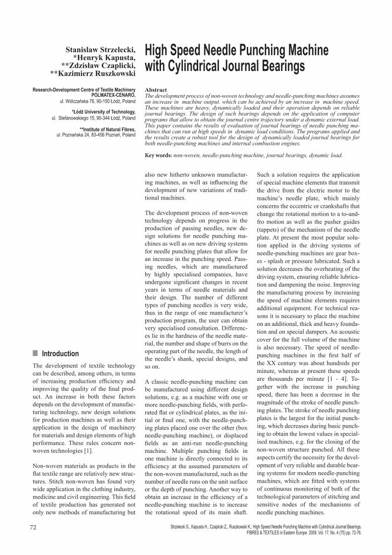
Figure 3 introduces the run of the re-sultant force of inertia W calculated us-ing the following data: mp = 24.2 kg, n1 = 4000 r.p.m., a = 1, b = 0.5, r = 0.015 m, l = 0.136 m, l = 0.111.
The resultant inertia force of 1st and 2nd order at a = 1; b = 0.5; l = 0.111;
2max 611,0 w⋅⋅= rmW p
n Journal centre trajectoryThe main bearings of needle punching machines are loaded with large radial dy-namic forces [1 - 5]. The reliable opera-tion of a machine and its stable motion depend on the bearings.
Knowledge of journal centre trajectory [7, 11] allows the determination of the minimum oil film thickness, the maxi-mum value of pressure and temperature distributions, i.e. the magnitudes required for the correct design of a journal bear-ing. The bearing clearance, the radius of operating surfaces of the bush and their displacement with regard to the circle in-scribed in the bearing profile as well as the length of the bearing are magnitudes which can be established on the basis of the journal centre trajectory.
As a result of numerical analysis of a dynamically loaded cylindrical journal bearing [2 - 5], the pressure distribution and resultant force of the oil film, and the journal centre trajectory are obtained. The character and value of these loads determine equation (1) and Figure 1. The classic, cylindrical journal bearing with the geometry of lubrication gap given by equation (3) has been assumed for con-sideration:
( )aje −⋅−= cos1cH (3)
where: e - relative eccentricity of the bearing, a - attitude angle, j - peripheral co-ordinate.
The journal centre trajectory of the jour-nal bearing considered was determined
by numerical solution of the Reynolds, energy, viscosity and geometry of the oil film equations. The method [3, 11] ap-plied for the solution of the Reynolds, energy, and viscosity equations and for determining the journal centre trajectory is characterised by the assumption nec-essary for describing the phenomena of lubrication and the dynamic of the tribo-logical system: journal-lubricant-bearing bush, i.e.:n the adding of pressures in the calcula-
tion of the components of the resultant hydrodynamic force,
n assumption of non-deformable journal and bush.
The method also assumes: n conditions of heat exchange - isother-
mal or adiabatic model with the tem-perature determined from the heat bal-ance,
n boundary conditions of the oil film - zones of negative pressure are ne-glected.
The Reynold’s equation applied in the calculation of the journal centre trajecto-ry has the form of equation (4) [11 - 17], where: D - bearing diameter, L - bearing length, H - dimensionless oil film thickness
p - dimensionless oil film pressure, Sh - Strouhal number, z - dimensionless axial co-ordinate, η - dimensionless vis-cosity of lubricant.
The pressure fields computed from equa-tion (4) allows to obtain the resultant force W of the bearing. Equating the oil film force W to the load F applied yields, at any instant, [5, 8],
F W LD
= ( , , , & , & )e a e a (5)
the calculation of the eccentricity, atti-tude angle, i.e. the journal centre trajec-tory in the function of the rotation angle of the driving shaft. The Runge-Kutta method has been applied for journal cen-tre trajectory calculation [11]. Oil film temperature distributions were obtained from the coupled solution of pressure and energy equations [8, 12, 14].
n Results of calculationCalculation have been carried out for a set of cylindrical journal bearings as well as for 2-pocket cylindrical ones with a different arrangement of the pockets. Ap-
Figure 3. Dynamic load of bearing at the rotational speed of 4000 r.p.m.
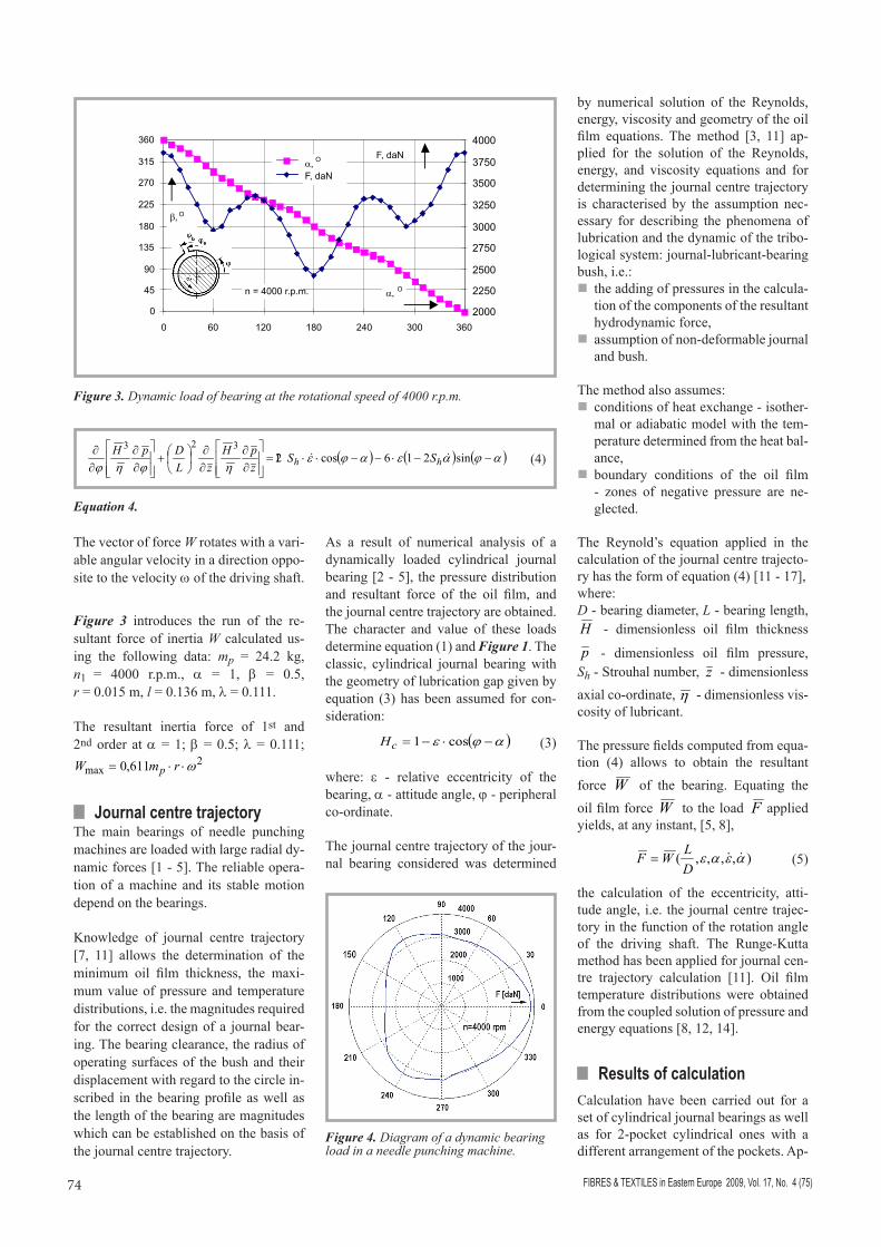
Figure 4. Diagram of a dynamic bearing load in a needle punching machine.
( ) ( ) ( )ajaeajeηjηj
−−⋅−−⋅⋅=
∂∂
∂∂
+
∂∂
∂∂ sin216cos12
323&& hh SS
zpH
zLDpH
(4)
Equation 4.

75FIBRES & TEXTILES in Eastern Europe 2009, Vol. 17, No. 4 (75)
Figure 5. Journal trajectories in a dynamically loaded cylindrical and 2-pockets journal bearing of needle punching machine at different relative clearances of the bearing and different working conditions.
plication of pressurised lubrication and a supply of oil to two pockets allows to control the operation of the bearing. This paper concerns the results of calculation for the following cases: bearing diam-eter D = 85 mm; relative length of the bearing L = 51, L = 65, L = 85 mm, re-spectively, with aspect ratios L/D = 0.6, L/D = 0.812, and L/D = 1.0; journal speed n = 4000 r.p.m; relative clearance of the bearing y =1.0 ‰, y =1.2 ‰, and y =1,5 ‰. The dynamic load applied for the calculations is shown in Figure 4.
Exemplary results of journal trajectory calculations are presented in Figures 5. The oil film pressure and temperature distributions are shown in Figure 6.a & 7.b, which result from calculations that, at an assumed bearing length to diameter ratio, variations in the relative clearance of the bearing have an effect on the jour-nal trajectories. An increase in the rela-tive clearance of the bearing causes an increase in the magnitude of the journal trajectory (Figure 5). At an assumed relative clearance of the bearing, an in-crease in the bearing length to diameter ratio decreases the extent of the journal trajectory and increases the minimum oil film thickness (e.g. Figures 5.b & 5.c)
Journal trajectories in a dynamically loaded 2-pocket cylindrical journal bear-ing of a needle punching machine at dif-ferent relative clearances of the bearing are shown in Figure 5.c. There is a dif-ference in the shape of trajectory com-pared with that of the cylindrical journal bearing (e.g. Figures 5.b & 5.c).
Exemplary oil film pressure distributions for two points on the journal trajectory and for two types of bearings are shown in Figures 6. For both cases at relative ec-
Figure 6. Oil film pressure distribution in a cylindrical journal bearing at different point of the journal trajectory and different working conditions.
Figure 7. Oil film temperature distribution in a cylindrical journal bearing at an assumed point of journal trajectory and different working conditions.
centricities considered, there is a similar run of pressure curves (e.g. Figure 6.a). In the case of a 2-pockets bearing, there are two ranges of oil film pressure (Fig-ure 6.b), which is characteristic for such a type of bearings.
Exemplary distributions of the oil film temperature for two points on the journal trajectory are shown in Figures 7; at a small value of bearing relative eccentricity, e = 0.18, there is almost the same run of temperature distribution for both bearing
a) b) c)
a) b)
a) b)
length to diameter ratios considered (Fig-ure 7.a); the values of the maximum oil film temperature are almost equal. How-ever, at a larger value of bearing relative eccentricity, e = 0.38 there is a difference in the run of oil film temperatures of the bearing calculated (Figure 7.b), with the maximum oil film temperatures reach-ing 102 °C and 87 °C for the bearing length to diameter ratios L/D = 0.6 and L/D = 1.0, respectively.

FIBRES & TEXTILES in Eastern Europe 2009, Vol. 17, No. 4 (75)76
The oil film thickness and its minimum value are the most important bearing characteristics. The program of numeri-cal calculations allows to obtain both pa-rameters on the assumption of different bearing geometric and operational data. It is possible to analyse the effect of bear-ing parameters on both these perform-ances.
The run of load and corresponding values of the oil film thickness for a cylindrical journal bearing can be observed in Fig-ure 8. At a smaller value of the bearing’s relative clearance, y = 1.0 ‰, the value of the oil film thickness H ranges from about 19 mm up to 32 mm (Figure 8).
n ConclusionsAs result of the analysis and calculations of the journal centre trajectory for differ-ent types of journal bearings of a needle punching machine, the following conclu-sions can be drawn.
The journal centre trajectories for the types of cylindrical journal bearings con-sidered depend on the profile of the bear-ing.
All trajectories obtained have a profile that is close to a deformed ellipse.
A trajectory close to a triangle with rounded tips was obtained for an asym-metrical cylindrical 2-pocket bearing.
Oil film pressures and temperature dis-tributions on the journal peripheral are similar for different angles j, resulting from the similarity of dynamic forces.
At an assumed dynamic load of the bear-ing, an increase in its relative clearance causes a decrease in the minimum oil film thickness.
The method of calculation and programs developed give a robust and very effi-cient tool that can be applied in the de-sign process of dynamically loaded jour-nal bearings of different profiles that op-erate, e.g. in needle punching machines.
References1. Kapusta H. Dynamic analysis of needle
machine. Research report Technical Uni-versity of Łódź 1998.(in Polish)
2. Kapusta H., Strzelecki S., Numerical Analysis of Needle Punching Machine Journal Bearings Operation. VI Interna-tional Textile Conference IMTEX”2000. Łódź 2000. Textile Research. Scientific Bulletin Technical University of Lodz. No. 58. 341-347.
3. Kapusta H., Strzelecki S., Numerical analysis of slide bearings of a needle punching machine (in Polish). Procedings of 6th International Science Conference IMTEX”2000. Informatyka Włókienniczej Inżynierii Mechanicznej i Informatyka we Włókienniczej Inżynierii Chemicznej, Łódź 2000. 1-6.
4. Strzelecki S., Swiatek J., Oil film pressure distribution in the dynamically loaded bearings of needle loom machine. SLAVYANTRIBO 6, 2004. Sankt Peters-burg.2004 Rybinsk 2004. Russia. Vol. 2. 257-265.
5. Kapusta H., Strzelecki S., Tribological System of Dynamically Loaded Journal Bearings of Needle Punching Machine. First Mediterranean Tribology Conferen-ce, Jerusalem, 8-9 November 2000.
6. Jędrzejewski J. Mechanics of crankshaft systems of combustion engines. 1986.(in Polish)
7. Carl T., Das zylindrische Gleitlager unter konstanter und sinisformiger Belastung. Eine experimentelle Untersuchung. Diss. TU Fridericana Karlsruhe.1962.
8. Strzelecki S., Someya T., Maximum Oil Film Pressure and Temperature of Dynamically Loaded Journal Bearing. Proceedings of the 5th International Tri-bology Conf. in Australia. 6-9 December 1998. Brisbane, 219-224.
9. Strzelecki S., Maximum pressure and stresses in the dynamically loaded journal bearing with the peripheral oil groove. Journal of KONES 1997 Vol.2 No. 1 KONES’97. 23rd International Scientific Conference on Combustion Engines. Bielsko-Biała, Poland 1997, 433-438
10. Strzelecki S., Wójcicki R., Mixed lubri-cation in the dynamically loaded journal bearings. W, Journal of KONES. Internal Combustion Engines. Vol. 5, no 1. War-saw, Scientific Publication of Permanent Committee of KONES, 1998; 294-299.
11. Strzelecki S., Journal centre trajectory of dynamically loaded Offset-Halves bearing Proceedings of the 3rd International Con-ference of Tribology, BALKANTRIB’99, June 1- 4 th 1999, Vol. II, Sinaia, Roma-nia. 373-378.
12. Strzelecki S., Thermoelastohydrody-namic analysis of dynamically loaded journal bearings. 26th Int. Conference on Combustion Engines, KONES 2000. Nałęczów, 10-13 Sept. 2000, 497-502.
13. Strzelecki S., Problems of dynamically loaded engine journal bearings. Między-narodowa Konferencja Motoryzacyjna ‘2000. KONMOT-AUTOPROGRES, Doskonalenie Konstrukcji, Technologii i Eksploatacji Pojazdów. 17-20.10.2000, Zakopane. Nr 20, 391-400.
14. Strzelecki S., Computation of Thermo-Elastic Deflections of Dynamically Lo-aded Cylindrical Journal Bearings. 27th Int. Conference on Combustion Engines, KONES 2001. September 9 - 12, 2001, Jastrzêbia Góra. Conference Proce-edings. 216 - 224.
15. Strzelecki S., Ghoneam, S. M., Dy-namically Loaded Cylindrical Journal Bearing with Recess. KONES 2004. Zakopane.2004. Journal of Kones Vol. 11, No.3-4. 234-241.
16. Strzelecki S., Swiatek J., Dynamically Loaded 2-Lobe Journal Bearing. Proc. of the 11th Nordic Symposium on Tribology NORDTRIB2004. Tr�mso- Harstad-Hur-Tr�mso- Harstad-Hur-tigruten. Norway. June 2004. 477-487.
17. Strzelecki S., Swiatek J., Dynamically Loaded 2-Lobe Journal Bearing. TRI-BOLOGIA. Helsinki, Finland. September 2004. Finnish Journal of Tribology. Vol. 23/2004. 13-22.
Figure 8. The run of load and oil film thickness versus the crank angle.
Received 26.02.2008 Reviewed 02.03.2009