high speed naval craft 2003 - american bureau of … · abs guide for building and classing...
TRANSCRIPT
GUIDE FOR BUILDING AND CLASSING
HIGH SPEED NAVAL CRAFT 2003
PART 3 HULL CONSTRUCTION AND EQUIPMENT
American Bureau of Shipping Incorporated by Act of Legislature of the State of New York 1862
Copyright 2002 American Bureau of Shipping ABS Plaza 16855 Northchase Drive Houston, TX 77060 USA

This Page Intentionally Left Blank

ABS GUIDE FOR BUILDING AND CLASSING HIGH-SPEED NAVAL CRAFT . 2003 iii
P A R T
3 Hull Construction and Equipment
CONTENTS CHAPTER 1 General....................................................................................1
Section 1 Definitions .................................................................3 Section 2 General Requirements............................................11 Section 3 Direct Analysis Methods .........................................19
CHAPTER 2 Hull Structures and Arrangements.....................................31
Section 1 Primary Hull Strength..............................................43 Section 2 Design Pressures....................................................57 Section 3 Plating .....................................................................75 Section 4 Internals ..................................................................95 Section 5 Hull Structural Arrangement .................................109 Section 6 Arrangement, Structural Details and
Connections ..........................................................115 Section 7 Keels, Stems and Shaft Struts..............................131 Section 8 Rudders ................................................................135 Section 9 Protection of Deck Openings ................................145 Section 10 Protection of Shell Openings ................................155 Section 11 Bulwarks, Rails, Ports, Portlights, Windows,
Ventilators, Tanks Vents and Overflows...............169 Section 12 Protective Coatings...............................................179 Section 13 Welding, Forming and Weld Design .....................183 Appendix 1 Guidelines for Calculating Bending Moment
and Shear Force in Rudders and Rudder Stocks ...................................................................187
Appendix 2 Guide on Analysis of the Cross Deck Structure of a Multi-hull Craft................................................191
Appendix 3 Alternative Method for Determination of “V” Shaft Strut Requirements .....................................195
iv ABS GUIDE FOR BUILDING AND CLASSING HIGH-SPEED NAVAL CRAFT . 2003
CHAPTER 3 Subdivision and Stability .................................................. 199 Section 1 General Requirements..........................................201 Appendix 1 Alternative Requirements for the Subdivision
and Stability of High Speed Naval Craft ...............203 Appendix 2 Onboard Computers for Stability Calculations......215
CHAPTER 4 Fire Safety Measures ......................................................... 223
Section 1 Structural Fire Protection ......................................225 CHAPTER 5 Equipment .......................................................................... 227
Section 1 Anchoring and Mooring Equipment ......................229 Appendix 1 Alternative Standard for the Required Anchor
Size .......................................................................243 CHAPTER 6 Testing, Trials and Surveys During
Construction – Hull............................................................ 245 Section 1 Tank, Bulkhead and Rudder Tightness Testing ...247 Section 2 Trials .....................................................................249 Section 3 Surveys .................................................................251

ABS GUIDE FOR BUILDING AND CLASSING HIGH-SPEED NAVAL CRAFT . 2003 1
P A R T
3 C H A P T E R 1 General
CONTENTS SECTION 1 Definitions...............................................................................3
1 Application .............................................................................3 3 Length ....................................................................................3 5 Breadth ..................................................................................3 7 Depth .....................................................................................3 9 Draft for Scantlings ................................................................3 11 Decks .....................................................................................4
11.1 Freeboard Deck ................................................................ 4 11.3 Bulkhead Deck .................................................................. 4 11.5 Strength Deck ................................................................... 4 11.7 Superstructure Deck ......................................................... 4
13 Superstructure .......................................................................4 15 Deckhouses ...........................................................................4 17 Displacement and Block Coefficient ......................................4
17.1 Displacement .................................................................... 4 17.3 Block Coefficient (Cb) ........................................................ 4
17 Deadweight (DWT) .................................................................5 19 Significant Wave Height.........................................................5 21 Rabbet Line (Fiber Reinforced Plastic)..................................5 23 Naval Administration..............................................................5 25 Military Personnel ..................................................................5 27 Passenger..............................................................................5 29 Safe Harbor............................................................................5 31 Fiber-Reinforced Plastic (FRP)..............................................6
31.1 Reinforcement................................................................... 6 31.3 Resin................................................................................. 7 31.5 Laminate ........................................................................... 9 31.7 Encapsulation.................................................................. 10
33 Units .....................................................................................10

2 ABS GUIDE FOR BUILDING AND CLASSING HIGH-SPEED NAVAL CRAFT . 2003
SECTION 2 General Requirements......................................................... 11 1 Materials...............................................................................11
1.1 Selection of Material Grade .............................................11 1.3 Note for the Users ...........................................................12 1.5 6000 Series Aluminum Alloys..........................................12
3 Workmanship .......................................................................13 5 Design..................................................................................13
5.1 Continuity ........................................................................13 5.3 Openings .........................................................................14 5.5 Brackets ..........................................................................14 5.7 Structural Design Details .................................................16 5.9 Termination of Structural Members .................................17
7 Effective Width of Plating.....................................................17 7.1 FRP Laminates................................................................17 7.3 Steel and Aluminum Plating ............................................18
TABLE 1 Material Grades..........................................................11 TABLE 2 Material Class of Structural Members........................12 TABLE 3A Brackets (Steel)..........................................................15 TABLE 3B Brackets (Aluminum)..................................................15 FIGURE 1..........................................................................................13 FIGURE 2..........................................................................................14 FIGURE 3..........................................................................................14 FIGURE 4 Bracket .......................................................................16 FIGURE 5 Effective Width of FRP Plating...................................18
SECTION 3 Direct Analysis Methods ..................................................... 19
1 General ................................................................................19 3 Loading Conditions ..............................................................19
3.1 General............................................................................19 3.3 Environmental and Service Conditions............................20 3.5 Loading Conditions for Direct Analysis ............................20
5 Motion Predictions ...............................................................22 5.1 Model Testing..................................................................22 5.3 Accelerations from Direct Analysis ..................................23
7 Load Predictions ..................................................................23 7.1 Global Loads ...................................................................23 7.3 Local Loads .....................................................................24
9 Structural Response ............................................................26 9.1 Global Response.............................................................26 9.3 Local Response...............................................................27
11 Structural Acceptability ........................................................29 11.1 Beam, Grillage, or Plane Frame Analysis........................29 11.3 Finite Element Analysis ...................................................29
TABLE 1 Sea States..................................................................19

ABS GUIDE FOR BUILDING AND CLASSING HIGH-SPEED NAVAL CRAFT . 2003 3
P A R T
3 C H A P T E R 1 General
S E C T I O N 1 Definitions
1 Application
The following definitions of terms apply throughout the requirements in this Guide.
3 Length
L is the distance, in meters (feet), on the full load design waterline in the displacement mode, from the fore side of the stem to the centerline of the rudder stock. For use with this Guide, L is not to be less than 96% and need not be greater than 97% of the length on the full load design waterline in the displacement mode. The forward end of L is to coincide with the fore side of the stem on the waterline on which L is measured.
5 Breadth
B is the greatest molded breadth, in meters (feet).
Breadth used in 3-2-1/1.1.1 for craft which have flare or tumblehome, is the mean breadth of the waterline breadth and the maximum breadth between the waterline and main deck at the longitudinal center of flotation (LCF).
7 Depth
D is the molded depth, in meters (feet), measured at the middle of the length L, from the molded keel line to the top of the freeboard deck beams at the side of the craft. On craft with rabbeted keel construction, D is to be measured from the rabbet line. In cases where watertight bulkheads extend to a deck above the freeboard deck and are to be recorded in the Record as effective to that deck, D is to be measured to the bulkhead deck.
9 Draft for Scantlings
d is the draft, in meters (feet), measured at the middle of the length L from the molded keel or the rabbet line at its lowest point to the estimated summer load waterline or the design load waterline in the displacement mode.
Part 3 Hull Construction and Equipment Chapter 1 General Section 1 Definitions 3-1-1
4 ABS GUIDE FOR BUILDING AND CLASSING HIGH-SPEED NAVAL CRAFT . 2003
11 Decks
11.1 Freeboard Deck
The freeboard deck is normally the uppermost continuous deck having permanent means for weathertight closing of all openings in its weather portions, and below which all openings in the craft side are equipped with permanent means for watertight closure.
11.3 Bulkhead Deck
The bulkhead deck is the highest deck to which watertight bulkheads extend and are made effective.
11.5 Strength Deck The strength deck is the deck which forms the top of the effective hull girder at any part of its length. See Section 3-2-1.
11.7 Superstructure Deck
A superstructure deck is a deck above the freeboard deck to which the side shell plating extends or of which the sides are fitted inboard of the hull side not more than 4% of the breadth, B. Except where otherwise specified, the term superstructure deck where used in this Guide refers to the first such deck above the freeboard deck.
13 Superstructure
A superstructure is an enclosed structure above the freeboard deck having side plating as an extension of the shell plating, or not fitted inboard of the hull side more than 4% of the breadth B.
15 Deckhouses A deckhouse is an enclosed structure above the freeboard deck, having side plating set inboard of the hull side-shell plating more than 4% of the breadth B of the craft.
17 Displacement and Block Coefficient
17.1 Displacement
The displacement ∆, is the mass displacement of the craft in the design condition in metric tons (long tons), unless otherwise specifically noted.
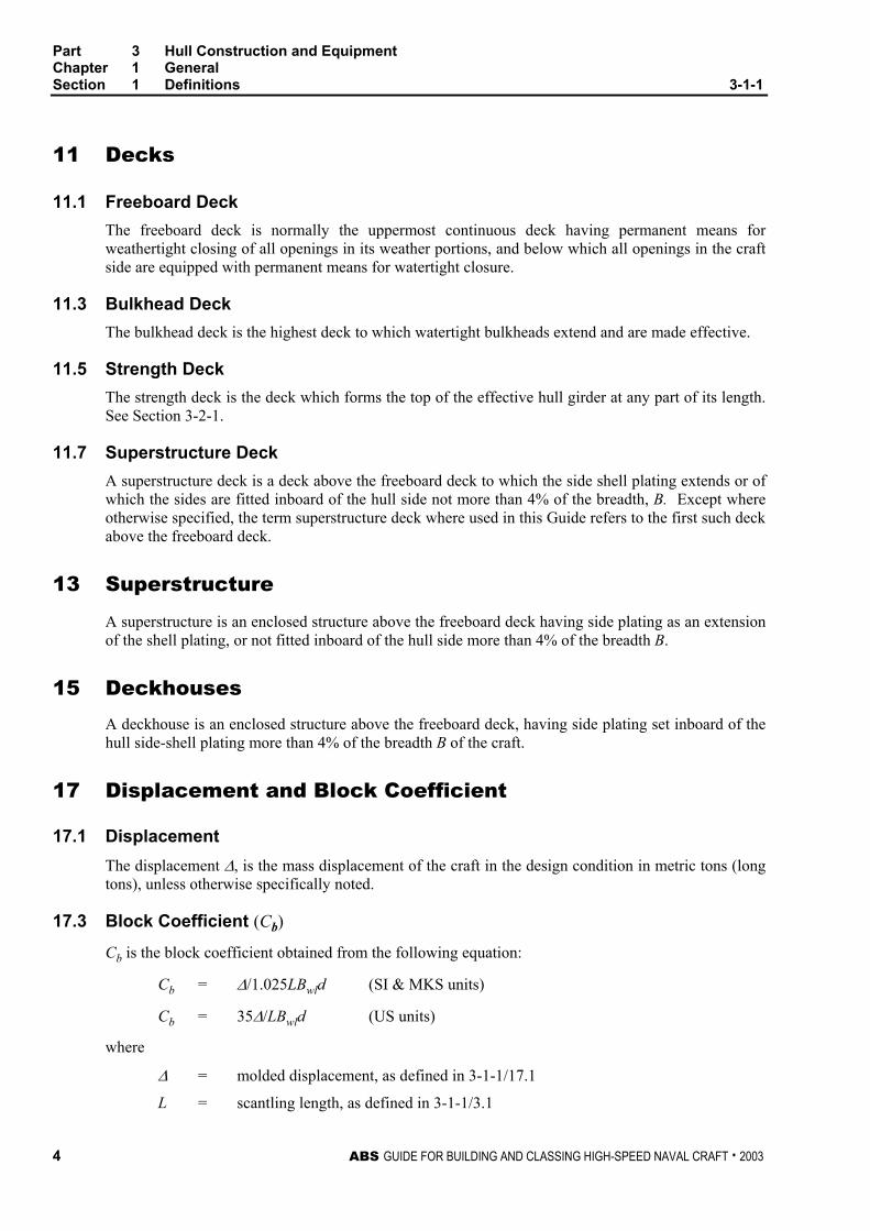
17.3 Block Coefficient (Cb)
Cb is the block coefficient obtained from the following equation:
Cb = ∆/1.025LBwld (SI & MKS units)
Cb = 35∆/LBwld (US units)
where
∆ = molded displacement, as defined in 3-1-1/17.1
L = scantling length, as defined in 3-1-1/3.1

Part 3 Hull Construction and Equipment Chapter 1 General Section 1 Definitions 3-1-1
ABS GUIDE FOR BUILDING AND CLASSING HIGH-SPEED NAVAL CRAFT . 2003 5
d = draft, as defined in 3-1-1/9
Bwl = greatest molded breadth at the design load line
17 Deadweight (DWT) For the purpose of this Guide, deadweight (DWT), is the difference, in metric tons (long tons), between the displacement of the craft at its summer load line or the craft with all tanks filled, maximum cargo loaded, maximum stores, and naval personnel or passengers and their effects on board, in water having a specific gravity of 1.025, and the unloaded weight of the craft. For the purpose of this Guide, the unloaded weight is the displacement of the craft, in metric tons (long tons), with no cargo, fuel, lubricating oil, ballast water, fresh water nor feed water in tanks, no consumable stores, and no naval personnel or passengers nor their effects.
19 Significant Wave Height Significant wave height is the average height of the one-third highest observed wave heights over a given period.
21 Rabbet Line (Fiber Reinforced Plastic)
The rabbet line is the line intersection between the outside of a craft’s bottom and a craft’s keel. Where there is no keel, the rabbet line is the bottom of the craft.
23 Naval Administration
The department, directorate, bureau or command to whom the National Government has delegated authority over the acquisition, acceptance, maintenance and technical requirements of naval vessels, and who acts on the Government’s behalf in all matters relating to the procurement and support of the vessels. In the case where these authorities are invested in separate departments within the naval organization, the term “Naval Administration” means the ensemble of departments having those authorities, or the command that overarches these departments. The Naval Administration may exist as part of the Navy, or within a separate arm of the government, such as a material procurement directorate.
25 Military Personnel
All people that are riding the craft, including the crew, that either have a function in the operation of the craft or are trained personnel that are taking part in the overall mission of the craft.
27 Passenger
Any personnel on the craft other than military personnel as defined above in 3-1-1/29
29 Safe Harbor
A friendly natural or artificial sheltered area which may be used as a shelter by a craft under conditions likely to endanger its safety.

Part 3 Hull Construction and Equipment Chapter 1 General Section 1 Definitions 3-1-1
6 ABS GUIDE FOR BUILDING AND CLASSING HIGH-SPEED NAVAL CRAFT . 2003
31 Fiber-Reinforced Plastic (FRP)
FRP consists of two basic components: a glass-filament or other material fiber reinforcement and a plastic, or resin, in which the reinforcing material is imbedded.
31.1 Reinforcement Reinforcement is a strong, inert material bonded into the plastic to improve its strength, stiffness and impact resistance. Reinforcements are usually fibers of glass (a lime-alumina-silicate composition having a low alkali content) or other approved material such as aramid or carbon fiber, in a woven or non-woven form, with a strong adhesive bond to the resin.
31.1.1 Strand A bundle of continuous filaments combined in a single, compact unit.
31.1.2 Roving A band or ribbon of parallel strands grouped together.
31.1.3 Yarn A twisted strand or strands suitable for weaving into a fabric.
31.1.4 Binder The agent applied in small quantities to bond the fibers in mat form.
31.1.5 Coupling Agent An active water soluble chemical that allows resin to adhere to glass.
31.1.6 Chopped-strand Mat A blanket of randomly oriented chopped-glass strands held together with binder.
31.1.7 Woven Roving A coarse fabric woven from rovings.
31.1.8 Cloth A fabric woven from yarn
31.1.9 Peel-Ply An “E” glass fabric that does not have any coupling agent applied, used as a protective covering on a laminate being prepared for a secondary bond to keep foreign particles from adhering to the surface.
31.1.10 Uni-directional A woven or non-woven reinforcement with substantially more fibers in one principal axis of the reinforcing ply.
31.1.11 Double Biased A woven or non-woven reinforcement with fibers primarily at +45° to the principal axes of the reinforcing ply.
31.1.12 Knitted or Stitched Fabrics Two or more layers of unidirectional fabrics that are stitched together.
Part 3 Hull Construction and Equipment Chapter 1 General Section 1 Definitions 3-1-1
ABS GUIDE FOR BUILDING AND CLASSING HIGH-SPEED NAVAL CRAFT . 2003 7
31.1.13 Bi-axial Fabric A stitched or knitted reinforcement with fibers primarily in the two principal axes of the reinforcing ply.
31.1.14 Tri-axial Fabric A stitched or knitted reinforcement with fibers running in one principal axis of the ply and in addition, with fibers running at + and -45° to the warp.
31.1.15 Ply Principal Axes The two principal axes of a reinforcing ply are the axis that is parallel to the warp and the axis that is parallel to the fill.
31.1.16 Warp The roving or yarn running lengthwise in woven fabric (in the “roll direction”).
31.1.17 Fill, Weft or Woof The roving or yarn running at right angles to the warp in a woven fabric.
31.1.18 “E” glass A family of glass reinforcement material of aluminoborosilicate composition and having high electrical resistivity.
31.1.19 “S” glass A family of glass reinforcement material of magnesium aluminosilicate composition that contains a higher silicon content and provides higher strength and stiffness properties than “E” glass.
31.1.20 Kevlar An aramid fiber reinforcement.
31.1.21 Carbon Fiber A reinforcement material made of mostly carbon produced by the pyrolysis of organic precursor fibers in an inert environment.
31.3 Resin Resin is a highly reactive synthetic that in its initial stage is a liquid, but upon activation is transformed into a solid.
31.3.1 Accelerator A material that, when mixed with a catalyst or resin, speeds the cure time.
31.3.2 Additive A substance added to another substance, usually to improve properties, such as plasticizers, initiators, light stabilizers and flame retardants.
31.3.3 Catalyst or Initiator A material that is used to activate resin, causing it to harden.
31.3.4 Crazing Hairline cracks, either within or on the surface of resin, caused by mechanical or thermal stresses.

Part 3 Hull Construction and Equipment Chapter 1 General Section 1 Definitions 3-1-1
8 ABS GUIDE FOR BUILDING AND CLASSING HIGH-SPEED NAVAL CRAFT . 2003
31.3.5 Cure To change resin from a liquid to a solid.
31.3.6 Cure time The time required for resin to change from a liquid to a solid after a catalyst has been added.
31.3.7 Exothermic Heat The heat given off as the result of the action of a catalyst on resin.
31.3.8 Filler A material added to resin to modify its working properties or other qualities, or to lower densities.
31.3.9 Gel A partially cured resin in a semi-solid state similar to gelatin in consistency.
31.3.10 Gel Time The time required to change a flowable, liquid resin into a nonflowing gel.
31.3.11 Inhibitor A material that retards activation or initiation of resin, thus extending shelf life or influencing exothermic heat or gel time.
31.3.12 Polymerization The reaction that takes place when resin is activated or initiated.
31.3.13 Pot Life The length of time that a catalyzed resin remains workable.
31.3.14 Shelf Life The length of time that an uncatalyzed resin maintains its working properties while stored in a tightly sealed, opaque container.
31.3.15 Tack The degree of stickiness of the resin.
31.3.16 Thixotropy The property or phenomenon, exhibited by some resins, of becoming jelly-like at rest but becoming fluid again when stirred or agitated. This facilitates the application of the resin to inclined or vertical surfaces
31.3.17 Polyester Resin A thermosetting resin that is formed by combining saturated and unsaturated organic acids. Such as orthophthalic and isophthalic acids.
31.3.18 Vinylester Resin A thermosetting resin that consists of a polymer chain and an acrylate or methacrylate termination.
31.3.19 Epoxy A resin that contains one or more of the epoxide groups.

Part 3 Hull Construction and Equipment Chapter 1 General Section 1 Definitions 3-1-1
ABS GUIDE FOR BUILDING AND CLASSING HIGH-SPEED NAVAL CRAFT . 2003 9
31.5 Laminate A laminate is a material composed of successive bonded layers, or plies, of resin and fiber or other reinforcing substances.
31.5.1 Bi-directional Laminate A laminate having essentially the same strength and elastic properties in the two in plane principal axes. Bi-directional laminates may be constructed of bi-axial, double bias, tri-axial, mat or unidirectional reinforcing layers, or a combination of any of these.
31.5.2 Uni-directional Laminate A laminate with substantially more of the fibers in the plane of the laminate oriented in one of the two principal axis of the laminate plane so that the mechanical properties along that axis are appreciably higher than along the other natural axis.
31.5.3 Sandwich Laminate A laminate consisting of two fiber reinforced plastic skins attached to a non-structural or structural core (see 3-1-1/31.7 “Encapsulation”).
31.5.4 Barcol Hardness A measurement of the hardness of a laminate and thereby the degree of completion of the cure.
31.5.5 Delamination The separation of the layers of material in a laminate.
31.5.6 Gel Coat The first resin applied to mold when fabricating a laminate to provide a smooth protective surface for the laminate.
31.5.7 Layup The process of applying to a mold the layers of resin and reinforcing materials that make up a laminate. These materials are then compressed or densified with a roller or squeegee to eliminate entrapped air and to spread resin evenly. Also a description of the component materials and geometry of a laminate.
31.5.8 Verified Minimum Mechanical Property The mechanical properties, in Part 2, Chapter 6, of laminates differing from the basic, verified by the appropriate test(s) listed in 2-6-1/Table 1.
31.5.9 Laminate Principal Axes The two principal axes of a square or rectangular plate panel are for the application of this Guide those perpendicular and parallel to the plate panel edges.
31.5.10 Vacuum Bagging A method used to apply a uniform pressure over an area by applying a vacuum to that area.
31.5.11 Resin Impregnation A process of construction for large layers of fabric that consists of running a roll of fabric through a resin bath to completely saturate the fabric.

Part 3 Hull Construction and Equipment Chapter 1 General Section 1 Definitions 3-1-1
10 ABS GUIDE FOR BUILDING AND CLASSING HIGH-SPEED NAVAL CRAFT . 2003
31.5.12 Resin Transfer Molding A closed mold method that mechanically pumps resin through dry fabric previously placed in the mold.
31.5.13 Resin Infusion A method of FRP construction that uses a vacuum to pull catalyzed resin through dry fabric.
31.5.14 Primary Bond The bond that is formed between two laminated surfaces when the resin on both surfaces has not yet cured.
31.5.15 Secondary Bond The bond that is formed between two laminated surfaces when the resin on one of the two surfaces has cured.
31.5.16 Post Cure The act of placing a laminate in an autoclave and raising the temperature to assist in the cure cycle of the resin.
31.5.17 Autoclave A large oven used in post curing large laminated parts.
31.7 Encapsulation The containment of a core material, such as softwoods, balsa, PVC (cross linked) or linear polymer, within FRP laminates. The cores may be structurally effective or ineffective.
31.7.1 Bedding Putty Material used to adhere the core material to the FRP skins.
31.7.2 Scores Slits cut into the core material to aid in forming the core to complex shapes.
33 Units
This Guide is written in three systems of units: SI units, MKS units and US customary units. Each system is to be used independently of any other system.
Unless indicated otherwise, the format of presentation in this Guide of the three systems of units is as follows:
SI units (MKS units, US customary units)
ABS GUIDE FOR BUILDING AND CLASSING HIGH-SPEED NAVAL CRAFT . 2003 11
P A R T
3 C H A P T E R 1 General
S E C T I O N 2 General Requirements
1 Materials
This Guide is intended for welded craft constructed of steel, welded craft constructed of aluminum, and fiber reinforced plastic (FRP) craft; complying with the requirements of Part 2, Chapters 1, 2, 5 and 6 respectively, including the Naval ship supplementary requirements indicated in Part 2, Chapter 11. The use of materials other than those specified in Part 2, Chapters 1, 2, 5, 6, 11 and the corresponding scantlings will be specially considered.
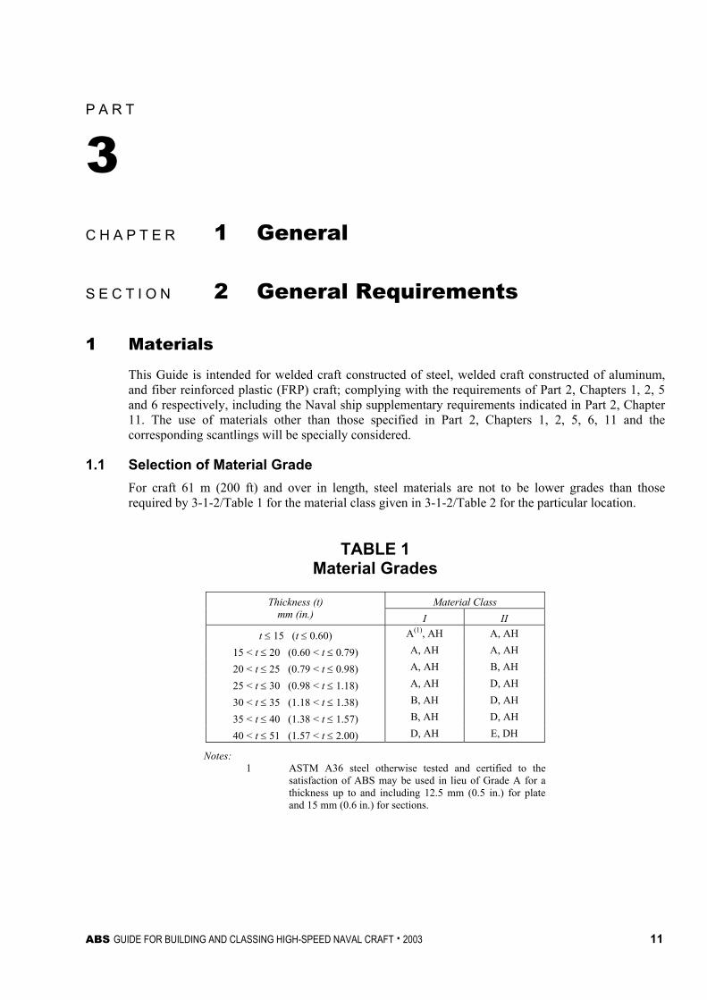
1.1 Selection of Material Grade For craft 61 m (200 ft) and over in length, steel materials are not to be lower grades than those required by 3-1-2/Table 1 for the material class given in 3-1-2/Table 2 for the particular location.
TABLE 1 Material Grades
Material Class Thickness (t) mm (in.) I II
t ≤ 15 (t ≤ 0.60) A(1), AH A, AH
15 < t ≤ 20 (0.60 < t ≤ 0.79) A, AH A, AH
20 < t ≤ 25 (0.79 < t ≤ 0.98) A, AH B, AH
25 < t ≤ 30 (0.98 < t ≤ 1.18) A, AH D, AH
30 < t ≤ 35 (1.18 < t ≤ 1.38) B, AH D, AH
35 < t ≤ 40 (1.38 < t ≤ 1.57) B, AH D, AH
40 < t ≤ 51 (1.57 < t ≤ 2.00) D, AH E, DH
Notes: 1 ASTM A36 steel otherwise tested and certified to the
satisfaction of ABS may be used in lieu of Grade A for a thickness up to and including 12.5 mm (0.5 in.) for plate and 15 mm (0.6 in.) for sections.

Part 3 Hull Construction and Equipment Chapter 1 General Section 2 General Requirements 3-1-2
12 ABS GUIDE FOR BUILDING AND CLASSING HIGH-SPEED NAVAL CRAFT . 2003
TABLE 2 Material Class of Structural Members
Material Class Structural members Within 0.4L Amidships Outside 0.4L
Amidships Shell
Bottom plating including keel plate II A(3)/AH Bilge strake II A(3)/AH Side Plating I A(3)/AH Sheer Strake at strength deck (1) II A(3)/AH Decks Strength deck plating (2) II A(3)/AH Stringer plate in strength deck (1) II A(3)/AH Strength deck strake on tankers at longitudinal bulkhead II A(3)/AH Strength deck plating within line of hatches and exposed to weather, in general
I A(3)/AH
Longitudinal Bulkheads Lowest strake in single bottom craft I A(3)/AH Uppermost strake including that of the top wing tank II A(3)/AH Other Structures in General External continuous longitudinal members and bilge keels II A(3)/AH Stem frames, rudder horns, rudders, shaft brackets - I Strength members not referred to in above categories and above local structures
A(3)/AH A(3)/AH
Notes: 1 A radius gunwale plate may be considered to meet the requirements for both the stringer plate and the sheer
strake, provided it extends suitable distances inboard and vertically. For formed material see 2-4-1/3.13.
2 Plating at the corners of large hatch openings are to be specially considered.
3 ASTM A36 steel otherwise tested and certified to the satisfaction of ABS may be used in lieu of Grade A for thickness up to and including 12.5 mm (0.5 in.) for a plate and 40 mm (1.57 in.) for sections.
1.3 Note for the Users The attention of users is drawn to the fact that when fatigue loading is present, the effective strength of higher-strength steel in a welded construction may not be greater than that of ordinary-strength steel. Precautions against corrosion fatigue to higher strength steel and aluminum alloy materials may also be necessary.
1.5 6000 Series Aluminum Alloys (1 January 2004) The use of 6000 series aluminum alloys is only permitted in structural applications in the extrusion form above the freeboard deck. The welded yield strength, σyw, for these alloys is based on the fully annealed condition, and is to be taken as 55 N/mm2 (5.5 kgf/mm2, 8000 psi). The use of 6000 series aluminum alloys in other locations is permitted only when approved in writing by the Naval Administration, and the following requirements are complied with:

Part 3 Hull Construction and Equipment Chapter 1 General Section 2 General Requirements 3-1-2
ABS GUIDE FOR BUILDING AND CLASSING HIGH-SPEED NAVAL CRAFT . 2003 13
i) The welding procedure is to be submitted for review and approval. This procedure will need to ensure process control in all welds and not allow for pre/post heating of the alloy. It will need to establish methods for certifying welders to this process and methods for inspection of the completed welds.
ii) Since pre/post heating is not permitted on 6000 series alloys, areas that can accumulate large “pre-stresses” such as the forward bow structure and water jet duct structure are to be examined. This examination is to include a determination of the actual pre-stress in the members and the reactions in the member when loaded with the required hydrostatic and slamming pressures.
iii) The procedure for the repair of the 6000 series alloys is to be submitted for review and approval. This procedure will need to demonstrate that the repair will not lower the heat affected zone below the level used for design.
The use of a welded yield strength, σyw, greater than the fully annealed condition may be considered when low heat welding techniques are used or with specialty extrusions that minimize the amount of weld. As part of this consideration, a test program will need to be established to validate the proposed welded yield strength. This test program is to include tensile, hardness, and fatigue “coupon” type testing of the alloy in the heat affected zone. Testing of samples that have been effectively repaired to determine the effects of multiple weld passes and the possible annealing of the alloy are also to be performed. In all cases, the Naval Administration is to confirm the use of the greater welded yield strength in writing.
3 Workmanship
All workmanship is to be of commercial marine quality and acceptable to the Surveyor. Welding is to be in accordance with the requirements of Part 2, Chapter 4, Appendix 2-5-A1, Part 2, Chapter 14, and Section 3-2-13.
5 Design
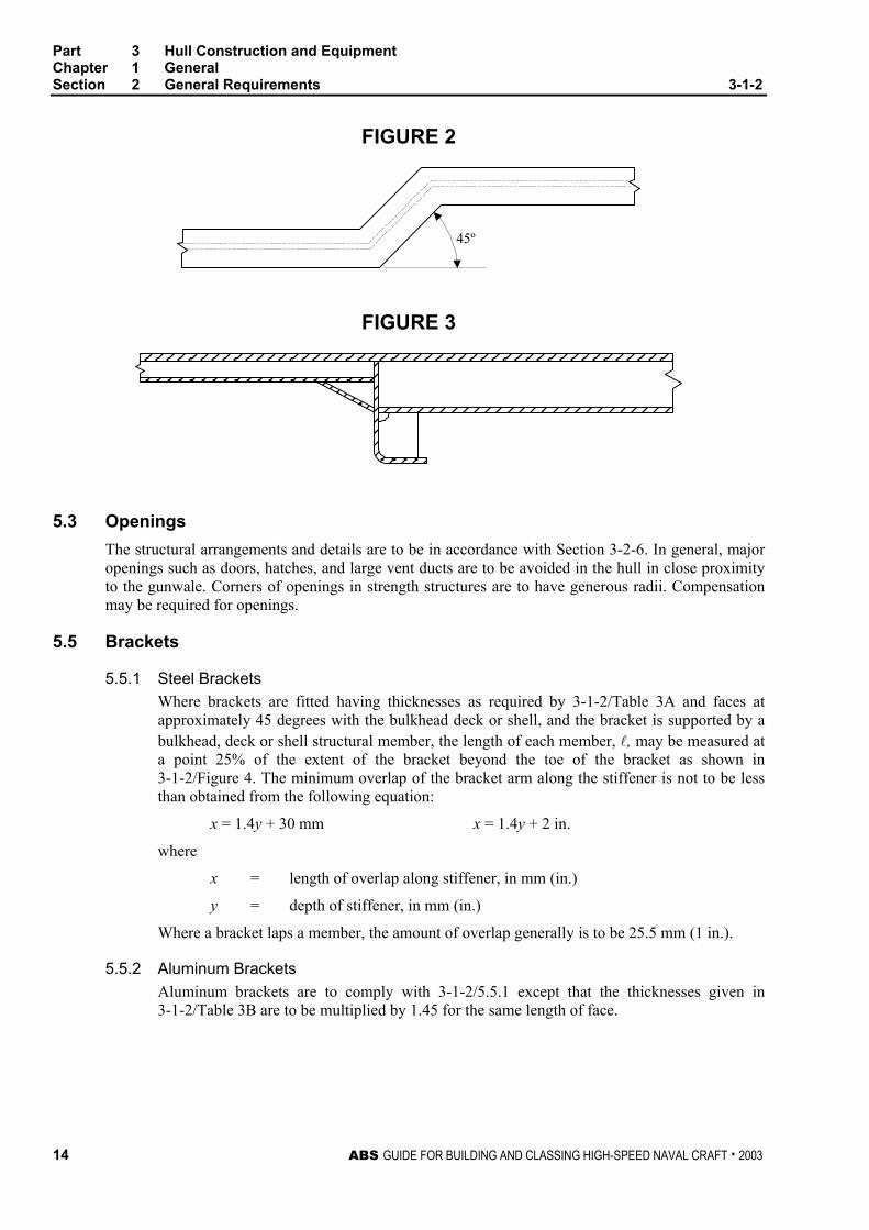
5.1 Continuity Care is to be taken to provide structural continuity. Changes in scantlings are to be gradual, such that the maximum angle from horizontal is 45°, see 3-1-2/Figure 1. Strength members are not to change direction abruptly, such that the maximum change in direction is 45°, see 3-1-2/Figure 2. Where primary structural members terminate at another structural member, tapering of the primary member or tapering brackets may be required beyond the other structural member, as indicated in 3-1-2/Figure 3, and as required in 3-2-5/1. Stanchions and bulkheads are to be aligned to provide support and to minimize eccentric loading. Major appendages outside the hull and strength bulkheads in superstructures are to be aligned with major structural members within the hull.
FIGURE 1
45º
Part 3 Hull Construction and Equipment Chapter 1 General Section 2 General Requirements 3-1-2
14 ABS GUIDE FOR BUILDING AND CLASSING HIGH-SPEED NAVAL CRAFT . 2003
FIGURE 2
45º
FIGURE 3
5.3 Openings The structural arrangements and details are to be in accordance with Section 3-2-6. In general, major openings such as doors, hatches, and large vent ducts are to be avoided in the hull in close proximity to the gunwale. Corners of openings in strength structures are to have generous radii. Compensation may be required for openings.
5.5 Brackets
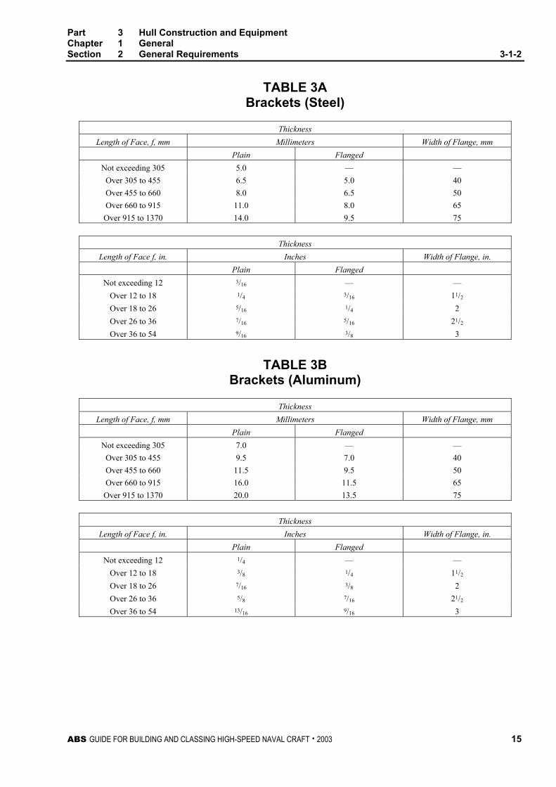
5.5.1 Steel Brackets Where brackets are fitted having thicknesses as required by 3-1-2/Table 3A and faces at approximately 45 degrees with the bulkhead deck or shell, and the bracket is supported by a bulkhead, deck or shell structural member, the length of each member, l, may be measured at a point 25% of the extent of the bracket beyond the toe of the bracket as shown in 3-1-2/Figure 4. The minimum overlap of the bracket arm along the stiffener is not to be less than obtained from the following equation:
x = 1.4y + 30 mm x = 1.4y + 2 in.
where
x = length of overlap along stiffener, in mm (in.)
y = depth of stiffener, in mm (in.)
Where a bracket laps a member, the amount of overlap generally is to be 25.5 mm (1 in.).
5.5.2 Aluminum Brackets Aluminum brackets are to comply with 3-1-2/5.5.1 except that the thicknesses given in 3-1-2/Table 3B are to be multiplied by 1.45 for the same length of face.
Part 3 Hull Construction and Equipment Chapter 1 General Section 2 General Requirements 3-1-2
ABS GUIDE FOR BUILDING AND CLASSING HIGH-SPEED NAVAL CRAFT . 2003 15
TABLE 3A Brackets (Steel)
Thickness Length of Face, f, mm Millimeters Width of Flange, mm
Plain Flanged Not exceeding 305 5.0 — —
Over 305 to 455 6.5 5.0 40 Over 455 to 660 8.0 6.5 50 Over 660 to 915 11.0 8.0 65 Over 915 to 1370 14.0 9.5 75
Thickness
Length of Face f, in. Inches Width of Flange, in. Plain Flanged
Not exceeding 12 3/16 — — Over 12 to 18 1/4 3/16 11/2 Over 18 to 26 5/16 1/4 2 Over 26 to 36 7/16 5/16 21/2 Over 36 to 54 9/16 3/8 3
TABLE 3B Brackets (Aluminum)
Thickness Length of Face, f, mm Millimeters Width of Flange, mm
Plain Flanged Not exceeding 305 7.0 — —
Over 305 to 455 9.5 7.0 40 Over 455 to 660 11.5 9.5 50 Over 660 to 915 16.0 11.5 65 Over 915 to 1370 20.0 13.5 75
Thickness
Length of Face f, in. Inches Width of Flange, in. Plain Flanged
Not exceeding 12 1/4 — — Over 12 to 18 3/8 1/4 11/2 Over 18 to 26 7/16 3/8 2 Over 26 to 36 5/8 7/16 21/2 Over 36 to 54 13/16 9/16 3

Part 3 Hull Construction and Equipment Chapter 1 General Section 2 General Requirements 3-1-2
16 ABS GUIDE FOR BUILDING AND CLASSING HIGH-SPEED NAVAL CRAFT . 2003
FIGURE 4 Bracket
f
ye x
l
0.25(e + x)
5.7 Structural Design Details The designer is to give consideration to the following:
5.7.1 The thickness of internals in locations susceptible to rapid corrosion.
5.7.2 The proportions of built-up members to comply with established standards for buckling strength.
5.7.3 The design of structural details such as noted below, against the harmful effects of stress concentrations and notches:
i) Details of the ends, the intersections of members and associated brackets.
ii) Shape and location of air, drainage or lightening holes.
iii) Shape and reinforcement of slots or cutouts for internals.
iv) Elimination or closing of weld scallops in way of butts, “softening” of bracket toes, reducing abrupt changes of section or structural discontinuities.
5.7.4 Proportions and thickness of structural members to reduce fatigue response due to engine, propeller or wave-induced cyclic stresses, particularly for higher-strength steels.
Standard construction details based on the above considerations are to be indicated on the plans or in a booklet submitted for review and comment.

Part 3 Hull Construction and Equipment Chapter 1 General Section 2 General Requirements 3-1-2
ABS GUIDE FOR BUILDING AND CLASSING HIGH-SPEED NAVAL CRAFT . 2003 17
5.9 Termination of Structural Members Unless permitted elsewhere in this Guide, structural members are to be effectively connected to the adjacent structures in such a manner to avoid hard spots, notches and other harmful stress concentrations. Where members are lightly loaded and not required to be attached at their ends, special attention is to be given to the end taper, by using soft-toed concave brackets or by a sniped end of not more than 30°. Bracket toes or sniped ends are to be kept within 25 mm (1.0 in.) of the adjacent member and the depth at the toe or snipe end is generally not to exceed 15 mm (0.60 in.). Where a strength deck or shell longitudinal terminates without end attachment, it is to extend into the adjacent transversely framed structure or stop at a local transverse member fitted at about one transverse frame space beyond the last floor or web that supports the longitudinal.
7 Effective Width of Plating
The section modulus and moment of inertia of stiffening members are provided by the member and a portion of the plating to which it is attached. The effective width is as given in the following paragraphs. The section modulus and moment of inertia of a shape, bar, fabricated section, or laid-up member not attached to plating is that of the member only.
7.1 FRP Laminates Where the plating is an FRP single-skin laminate, the maximum effective width of plating for floors, frames, beams and bulkhead stiffeners is not to exceed either the stiffening member spacing or the width obtained from the following equation, whichever is less. See 3-1-2/Figure 5.
w = 18t + b
where:
w = effective width of plating, in mm (in.)
t = thickness of single skin plating, in mm (in.)
b = net width of stiffening member, in mm (in.), but not more than 18t
Where the plating is an FRP sandwich laminate with a flexurally and compressively ineffective (balsa, cross linked PVC, or linear polymer) core, t in the above equation is the thickness of a single skin laminate having the same moment of inertia per unit width as the two skins of the sandwich about the neutral axis of the sandwich, excluding the core.
For a stiffening member along an opening, the maximum effective width of plating is equal to either one-half the stiffening member spacing or the width obtained from the following equation, whichever is less.
w = 9t + b
where w, t and b are as defined above.

Part 3 Hull Construction and Equipment Chapter 1 General Section 2 General Requirements 3-1-2
18 ABS GUIDE FOR BUILDING AND CLASSING HIGH-SPEED NAVAL CRAFT . 2003
FIGURE 5 Effective Width of FRP Plating
t
9t9t b
w = 18t + b
7.3 Steel and Aluminum Plating
7.3.1 Primary Structural Members The effective width of plating for deep supporting members is to equal to the lesser of either one half the sum of spacing on each side of the member, 0.33 time the unsupported span, l, or 750 mm (30 in.). For girders and webs along hatch openings, the effective width of plating is to be half of that obtained from the above. Due account is to be taken in regards to plate buckling, see 3-2-3/1.1.
7.3.2 All Other Structural Members The maximum effective width of plating is equal to either one-half the sum of spacing on each side of the member or the width obtained from the following equation, whichever is less.
Steel Members w = 80t
Aluminum Members w = 60t
where
w = effective width of plating, in mm (in.)
t = thickness of single skin plating, in mm (in.)
For a stiffening member along an opening, the maximum effective width of plating is one-half of the effective width given above.

ABS GUIDE FOR BUILDING AND CLASSING HIGH-SPEED NAVAL CRAFT . 2003 19
P A R T
3 C H A P T E R 1 General
S E C T I O N 3 Direct Analysis Methods
1 General
This Section states requirements for a variety of direct analysis methods that can be used in lieu of or in conjunction with the specific requirements given in Sections 3-2-1, 3-2-2, 3-2-3, and 3-2-4 or to meet the requirements in 1-1-4/3. If the structure of the craft complies with 3-1-3/3.5, 3-1-3/5.3, 3-1-3/7.1.2, 3-1-3/7.3, 3-1-3/9.1, 3-1-3/9.3.3, and 3-1-3/11.3 of this section and the requirements in Sections 3-2-1, 3-2-2, 3-2-3, and 3-2-4 it will be eligible to receive the SH-DLA Class Notation. For guidance on the SH-DLA class notation not given in this Section, see the ABS Guidance Notes on ‘Dynamic Load Approach’ and Direct Analysis for High Speed Craft.
3 Loading Conditions
3.1 General The loading conditions considered should include all intended operational conditions of the craft as specified by the Naval Administration. These operating conditions are to be defined by significant wave height, wave period, and maximum operating speed. 3-1-3/Table 1 is to be used when the significant wave height is given in terms of Sea States. When the wave period is not given, the most probable modal period is to be used in the analysis.
TABLE 1 Sea States
Sea State Significant Wave Height m (ft) 0-1 0.10 (0.3) 2 0.50 (1.6) 3 1.25 (4.1) 4 2.5 (8.2) 5 4 (13.1) 6 6 (19.7) 7 9 (29.5) 8 14 (45.9)
>8 >14 (45.9)

Part 3 Hull Construction and Equipment Chapter 1 General Section 3 Direct Analysis Methods 3-1-3
20 ABS GUIDE FOR BUILDING AND CLASSING HIGH-SPEED NAVAL CRAFT . 2003
3.3 Environmental and Service Conditions
3.3.1 General The environmental condition is anticipated to be described by appropriate sets of wave data. The sources and reliability of this data are to be submitted. The wave parameters used in the analysis are to be selected and documented based on the conditions given in the craft specification. If these parameters are to be used in conjunction with the requirements in 3-1-3/3.5, 3-1-3/5.3, 3-1-3/7.1.2, 3-1-3/7.3, 3-1-3/9.1, 3-1-3/9.3.3, and 3-1-3/11.3, then they should be compatible with the stochastic response and extreme value prediction methods.
3.3.2 Types of Wave Spectra 3.3.2(a) Deep-water Ocean Waves. Two-parameter spectra, such as the Bretschneider or P-M wave spectral formulations, are to be used. If the swell and wave components are known to interact, a bi-modal Ochi-Hubble spectrum is to be used. Directional spreading appropriate to coastal conditions is also to be applied.
3.3.2(b) Shallow-water Waves. Wave conditions that include the effects of bathymetry, wind field, coastal contours of the region are to be used. For fetch-limited sea conditions, JONSWAP spectrum or a modified version of the spectrum is to be used.
3.5 Loading Conditions for Direct Analysis
3.5.1 Dominant Load Parameters A list of Dominant Load Parameters (DLP) is to be developed. This will include select motion and load effect parameters. Other loads, such as those due to wave impacts on the bow and stern, flare and bottom slamming, wet-deck slamming (multi-hulls) and vibration effects on local structural strength, have to be treated separately. Considerations for slamming analysis are given in 3-1-3/3.5.7.
3.5.2 Load Cases Load cases are defined by a combination of craft loading conditions, a set of global motion and load effect parameters set forth in terms of each of the DLPs, other load components accompanying the DLPs and an equivalent wave system for the specified DLP. Justification for load cases selected for use in the structural analysis is to be submitted to the Bureau for review.
3.5.3 Analyses of Ship Motions, Wave Loads, and Extreme Values Calculations are to be made using the spectral analysis-based approach, which by definition relies on the use of Response Amplitude Operators (RAOs). Each RAO is to be calculated for regular waves of unit amplitude for a range of wave frequencies and wave headings that will be given below.
3.5.4 Essential Features of Spectral Analysis of Motions and Loads 3.5.4(a) General Modeling Considerations. The model of the hull should include the masses of all equipment, vehicles and supporting structure. There is also to be sufficient compatibility between the hydrodynamic and structural models so that the application of fluid pressures onto the finite element mesh of the structural model can be done appropriately.
For the load component types and structural responses of primary interest, software formulations derived from linear idealizations are deemed to be sufficient. The capabilities and limitations of the software are to be known, and in cases where the software is not known to the Bureau, it may be necessary to demonstrate the adequacy of the software.

Part 3 Hull Construction and Equipment Chapter 1 General Section 3 Direct Analysis Methods 3-1-3
ABS GUIDE FOR BUILDING AND CLASSING HIGH-SPEED NAVAL CRAFT . 2003 21
3.5.4(b) Diffraction-Radiation Methods. Computations of the wave-induced motions and loads are to be carried out through the application of seakeeping analysis codes utilizing three-dimensional potential flow based diffraction-radiation theory. Computation of the hydrodynamic pressures should take account of, as a minimum, all six degree-of-freedom rigid-body motions of the hull. These codes may be based either on linear (small) wave and motion amplitude assumptions or nonlinear (large) amplitude motion and wave formulations.
3.5.4(c) Panel Model Development. The Rankine source panel method is recommended for solving the hydrodynamic boundary value problem.
3.5.4(d) Motion and Load-Effect Response Amplitude Operators. For each loading condition, RAOs of all the selected DLPs are to be calculated. The RAOs are to represent the pertinent range of wave headings (β), in increments not exceeding 15 degrees. A range of wave frequencies is to be considered based on the route-specific wave conditions (see 3-1-3/3.3). The nominal range is 0.2 rad/s to 1.8 rad/s in increments of 0.05 rad/s.
The worst frequency-heading (ω, β) combination is to be determined from an examination of the RAOs for each DLP. Only the heading βmax and the wave frequency ωe at which the RAO of the DLP is a maximum, need to be used in DLA or direct analysis.
3.5.5 Extreme Values Analysis Extreme value analysis is to be performed for each DLP to determine the maximum values. An extreme value method that follows the so-called long-term approach is to be used. The use of a validated short-term extreme value approach, which is appropriate to the craft type and route-specific environmental data, will also be considered. The supplementary use of such a short-term approach to confirm or test the sensitivity of the long-term based design values is recommended.
The relevant value to be obtained from the long-term response analysis is the most probable extreme value (MPEV) having a probability of level of 10-8 in terms of wave encounters.
3.5.6 Equivalent Wave For each load case, an equivalent wave is to be determined which simulates the magnitude and location of the extreme value of the dominant load component of the load case.
The procedure to be used to determine the equivalent wave’s characterizing parameters is given in 3-1-3/3.5.5(a)-(c) below. 3-1-3/3.5.5(d) describes the formulations to establish the magnitude and distribution of the other load components accompanying the extreme value of the dominant load component in a load case.
3.5.5(a) Equivalent Wave Amplitude. The amplitude of the equivalent wave is to be determined using the extreme values of the DLP (see 3-1-3/3.5.4) and the RAO of that DLP occurring at the wave frequency and wave heading corresponding to the maximum amplitude (peak) of the RAO. The amplitude of the equivalent wave is given by:
awj = MPEVj /Max RAOj
where
awj = wave amplitude
MPEVj = Most Probable Extreme Value of the jth DLP at a probability level equivalent to the design criterion
Max RAOj = maximum amplitude of the jth DLP’s RAO
Part 3 Hull Construction and Equipment Chapter 1 General Section 3 Direct Analysis Methods 3-1-3
22 ABS GUIDE FOR BUILDING AND CLASSING HIGH-SPEED NAVAL CRAFT . 2003
3.5.7 Slamming Loads Loads due to slamming and wave impact on craft hulls are categorized into global slamming effects and local slam-induced structural response.
3.5.7(a) Global Slamming Effects. The simplified formulae given in Section 3-2-1 may be used to account for global slamming effects in the preliminary design stage. For detailed analysis, a direct time-domain simulation involving short-term predictions are to be used for the global strength assessment of monohulls. In most cases involving high speeds, the absolute motions or relative motions will be of such large amplitude that nonlinear calculations will be required. In catamarans, wet deck slam-induced global whipping effects of the hull is to be assessed using methods that account for coupling of the symmetric and anti-symmetric modes of responses. These calculations will require time-domain analysis methods.
3.5.7(b) Local Impact Loads. Panel structures with horizontal flat or nearly flat surfaces such as a wet deck of a multi-hull craft will need to be hydroelastically modeled, where in the dynamics of the fluid and the elastic response of the plate and stiffeners are simultaneously modeled.
5 Motion Predictions
5.1 Model Testing Craft hull motions and accelerations obtained from scale model tests may be used to validate motions predicted by computer programs. Model testing is required to be performed and reported to the Bureau when loads are being submitted in lieu of the loads determined in Section 3-2-2 or other loads determined by the Bureau. This paragraph is to be complied with when model testing is required by the Naval Administration. The model is to accurately represent the structure that is to be built in both principal particulars and hull geometry.
5.1.1 Testing Program The model is to be tested over a range of speeds, headings, and wave characteristics (height, length, and period), as indicated by the Naval Administration. When this is not specified, the testing program is to include the following: 5.1.1(a) Speeds. The model is to be tested at the minimum speed required by the Naval Administration and the maximum achievable speed of the craft for a particular wave profile and heading. 5.1.1(b) Headings. The model is to be tested in head, beam, quartering, and following seas. 5.1.1(c) Wave Parameters. The model is to be tested in both deep water and shallow water wave conditions. These are defined in 3-1-3/3.3.2. For craft that are limited to operation in coastal regions (Coastal Naval Craft and Riverine Naval Craft), deep water wave profile testing is not required.
5.1.2 Model Measurements and Reporting The parameters listed below are to be measured and reported based on the model test program. Some of the parameters listed may be derived through statistical analysis of measured data obtained from testing. When statistical analysis is used, the methods of analysis employed are to be indicated in the report. 5.1.2(a) Vertical or Heave Acceleration. The significant, 1/10
th highest, or 1/100th highest
vertical acceleration at the longitudinal center of gravity, bow, and stern are to be reported. The accelerometer is to be adjusted such that the acceleration due to gravity is not measured. The 1/100
th highest vertical acceleration at the longitudinal center of gravity may be used in place of ncg in 3-2-2/1 and 3-2-2/3.

Part 3 Hull Construction and Equipment Chapter 1 General Section 3 Direct Analysis Methods 3-1-3
ABS GUIDE FOR BUILDING AND CLASSING HIGH-SPEED NAVAL CRAFT . 2003 23
5.1.2(b) Roll Acceleration. The significant roll acceleration about a longitudinal axis through the center of gravity and the maximum roll angle are to be reported.
5.1.2(c) Pitch Angle and Acceleration. The significant coupled pitch-and-heave acceleration at the bow and the stern and the maximum pitch angle are to be reported.
5.3 Accelerations from Direct Analysis
5.3.1 General The wave-induced craft motions may be determined by direct analysis. When this analysis is not performed by the Bureau, it is to be verified by model testing as indicated in 3-1-3/5.3.
5.3.2 Global Accelerations Global accelerations are to be determined using the loading conditions indicated in 3-1-3/3.5 above. The 1/100
th highest vertical (heave) acceleration at the longitudinal center of gravity may be used in place of ncg in Sections 3-2-1 and 3-2-2.
5.3.3 Local Accelerations Local accelerations at points where the lightship weight of the structure, (non-liquid cargo), are located, including deck-mounted equipment, should be calculated to determine the inertia loads. For vehicle decks, wheel loading should be applied. An evenly distributed load equivalent to the weight of the vehicles may be used. The acceleration RAO at a location of interest is to be calculated to account for all translational and rotational components of motions.
The components of the gravitational acceleration in the craft’s coordinate system are to be included.
7 Load Predictions
7.1 Global Loads As a minimum, the still-water hogging and sagging moments and shear forces, the wave-induced hogging and sagging moments and shear forces and the slam-induced moments and shear force, are to be determined for monohull craft. Multi-hulled craft are to have the transverse bending moment, the torsional (or pitch connecting) moment and the transverse shear force determined in addition to the moments and shear forces determined for monohull craft. These loads are to be reported so that they can be used in conjunction with the requirements in 3-1-3/9 or Section 3-2-1.
7.1.1 Computation of Global Load Effects 7.1.1(a) Still-water Bending Moment and Shear Force. The still-water bending moments and shear forces are to be calculated in the light load, half load, and full load conditions. The light load condition consists of all components of the craft (structure, machinery, piping equipment, outfitting, wiring, interiors, paint, etc.) plus 10% of tank and cargo capacity. The half load condition is to include all components of the craft plus 50% of the tank and cargo capacity. The full load condition consists of all components of the craft plus 100% of the tank and cargo capacity. The distribution of the load is to capture all major weight discontinuities, and no single weight distribution segment is to be greater than 0.20L.
7.1.1(b) Wave-Induced Longitudinal Bending Moment and Shear Force. The wave-induced bending moments and shear forces can be determined by using the environmental conditions outlined in 3-1-3/3.3.

Part 3 Hull Construction and Equipment Chapter 1 General Section 3 Direct Analysis Methods 3-1-3
24 ABS GUIDE FOR BUILDING AND CLASSING HIGH-SPEED NAVAL CRAFT . 2003
7.1.1(c) Transverse Bending Moment and Shear Force – Multi-hulled Craft. The transverse bending moment and shear force may be determined by distributing the weights and loads athwartships across the craft and using the environmental conditions outlined in 3-1-3/3.3
7.1.1(d) Torsion Bending Moment. The torsional bending moment may be determined by distributing the weights and loads on segments of the hull sliced at a 45° angle from centerline and using the environmental conditions outlined in 3-1-3/3.3.
7.1.1(e) Slamming Induced Bending Moment and Shear Force. The slam induced bending moment and shear force may be calculated by applying the acceleration determined in 3-1-3/5 or in 3-2-2/1 to the lumped masses developed for 3-1-3/7.2.1(a).
7.1.2 Global Loads from Computations Global loads from computer software programs are to be developed by loading the structure as outlined in 3-1-3/3.5. The computer program is to be capable of determining the moments and shear forces in 3-1-3/7.1 or developing loads that can be used in conjunction with finite element methods as outlined in 3-1-3/9.1.
7.3 Local Loads Loads that differ from the pressure loads developed in Section 3-2-2 may be used to determine the required scantlings in conjunction with the requirements in 3-1-3/9.3 or Sections 3-2-3 and 3-2-4. These loads are to be developed under the loading conditions in 3-1-3/3 and the following subparagraphs.
7.3.1 External Hydrodynamic Pressure The hydrodynamic pressures at selected points on the external contours of the hull sections, are to be calculated in regular waves.
7.3.1(a) External Pressure Components. The total hydrodynamic pressure is to include the pressure components due to waves and the components due to craft motion. Components of the hydrodynamic pressure are to be calculated from the panel model analysis of 3-1-3/3.5.3.
7.3.1(b) Pressures Accompanying the Dominant Load Parameter and Their Distribution. The external pressure is to be calculated either as a complex number or in terms of the amplitude and phase. Then, ‘simultaneously’ acting pressures over the wetted surface can be represented in the form:
P = (A)(aw)sin(ωet + εI)
where
P = simultaneous pressure
A = amplitude of the pressure RAO
aw, ωe, t, and εI are as defined in 3-1-3/3.5.5(d).
7.3.1(c) Pressure Loading for Finite Element Models. The hydrodynamic pressure can be linearly interpolated to obtain the nodal pressures for the finite element models required for structural analysis.
7.3.1(d) Pressure Loading for Guide Requirements. For pressures that are to be used in conjunction with the requirements in Sections 3-2-3 and 3-2-4 for determining the local scantlings, the hydrodynamic pressures are to be resolved into kN/m2 (tf/m2, psi).
7.3.2 Internal Tank Pressure Liquid pressures in the cargo tanks are to be calculated and applied to the structural model used in finite element analysis. Both static and dynamic pressures should be included in the analysis, assuming that there is no relative motion between the tank and the contained fluid.

Part 3 Hull Construction and Equipment Chapter 1 General Section 3 Direct Analysis Methods 3-1-3
ABS GUIDE FOR BUILDING AND CLASSING HIGH-SPEED NAVAL CRAFT . 2003 25
7.3.2(a) Pressure Components. The internal tank pressure is to account for both the quasi-static and motion-induced (dynamic) pressure components. The quasi-static component results from gravity and should include craft roll and pitch rotations. The dynamic component is to be developed from the accelerations in the liquid at the tank boundary caused by the hull’s motions in six degrees of freedom. These are to be obtained from motion analysis as specified in 3-3-3/3.
The total instantaneous internal tank pressure for each of the tank boundary points is to be calculated by combining the inertial and quasi-static components as follows:
p = po + ρht[(gx + ax)2 + (gy +ay)2 + (gz + az)2]1/2
where
p = total instantaneous internal tank pressure at a tank boundary point
po = vapor pressure or the relief valve pressure setting
ρ = fluid density, cargo or ballast
ht = total pressure head defined by the height of the projected fluid column in the direction of the total instantaneous acceleration vector
ax,y,z = longitudinal, lateral, and vertical wave-induced accelerations relative to the craft’s axis system at a point on a tank’s boundary
gx,y,z = longitudinal, lateral, and vertical components of gravitational accelerations relative to the craft’s axis system at a tank boundary point
7.3.2(b) Roll and Pitch Motions. The influence of ship motions on tank pressures is to be taken into account using the maximum pitch and roll angles. As reflected in the previous formulations, the inclination of the tank due to craft roll and pitch is to be considered in the calculation of the hydrostatic pressure. The direction of gravitational forces in the ship-fixed coordinate system varies with roll and pitch, resulting in a change in pressure head and a corresponding change in the static pressure.
7.3.2(c) Simultaneously Acting Tank Pressure. At each wave condition, for each load case described in 3-1-3/3.5, simultaneously acting tank pressures (quasi-static and dynamic) are to be calculated. Each wave condition is defined by wave amplitude, frequency, heading angle and wave crest position, as explained in 3-1-3/3.5. Using the wave amplitude and phase angle determined based on the RAO of a DLP, the simultaneously acting tank pressure is to be calculated for the instant when the maximum value of the DLP occurs. These internal tank pressures are to be used in the structural finite element model.
7.3.3 Inertia Force of Lumped Structural Mass The inertia force, or point load, of a structural mass, such as deck equipment or cargo, can be determined by the following equation:
F = m(At)
where
F = inertial load of the item m = mass of the lumped weight of the structural member At = amplitude of the acceleration RAO
For finite element models, the inertia forces in three (global) directions are to be calculated and applied. For a first-principles analysis, the inertia force in the vertical direction is to be calculated and applied.

Part 3 Hull Construction and Equipment Chapter 1 General Section 3 Direct Analysis Methods 3-1-3
26 ABS GUIDE FOR BUILDING AND CLASSING HIGH-SPEED NAVAL CRAFT . 2003
9 Structural Response
9.1 Global Response The global bending moments developed in 3-1-3/7.1 can either be applied to the requirements in 3-2-1/1.1.2(e), 3-2-1/1.5, 3-2-1/1.9.4, and 3-2-1/3.5 or to a global finite element model as outlined in this paragraph.
9.1.1 General The load cases of 3-1-3/3.5 are to be applied to the global structural analysis model described in 3-1-3/9.1.4. Each load case is to include the hydrostatic and still-water load components that have not otherwise been directly included in the load component determination performed in accordance with 3-1-3/7.3.1 and 3-1-3/7.3.3. These hydrostatic or still-water components are to be included in the hydrostatics analysis.
9.1.2 Equilibrium Check The model of the hull girder structure should be close to equilibrium when all the loads (static and dynamic) are applied.
The unbalanced forces in the model’s global axis system for each load case need to be determined and resolved. The magnitudes of the unbalanced forces, and the procedure used to balance the structural model in equilibrium is to be fully documented.
9.1.3 General Modeling Considerations To the maximum extent practicable, the overall model of the hull structure should be comprised of the entire hull. There is also to be sufficient compatibility between the hydrodynamic and structural models so that the application of fluid pressures onto the finite element mesh of the structural model can be done appropriately.
For the load component types and structural responses of primary interest, analysis software formulations derived from linear idealizations are sufficient. Enhanced bases of analysis may be required so that non-linear loads, such as hull slamming, may be required. The adequacy of the selected software is to be demonstrated to the satisfaction of the Bureau.
The results of overall (global) model analysis are to be directly employed in the creation and analysis of the required finer mesh, local structural models. Appropriate boundary conditions determined in the larger scale model are to be imposed in the local models to assure appropriate structural continuity and load transfer between the various levels of models.
9.1.4 Analysis of the Global Hull Structure The global structural and load model is to be as detailed and complete as possible. The stress results of the global model are used only to assess the hull girder plating of the deck (and wet deck for multi-hulled craft), side shell, bottom, inner bottom, longitudinal bulkheads, transverse bulkheads and stools or deck box girders. The main supporting members of the hull girder may be evaluated using 2-D fine-mesh local models. In developing the 3-D global finite element model, the following requirements apply:
i) The finite element model is to include all primary load-carrying members. Secondary structural members which may affect the overall load distribution are also to be included.
ii) Structural idealization is to be based on the stiffness and anticipated response of the structure, not wholly on the geometry of the structure itself.
iii) The relative stiffness between associated structural members and their anticipated response under the specified loading is to be considered.
Part 3 Hull Construction and Equipment Chapter 1 General Section 3 Direct Analysis Methods 3-1-3
ABS GUIDE FOR BUILDING AND CLASSING HIGH-SPEED NAVAL CRAFT . 2003 27
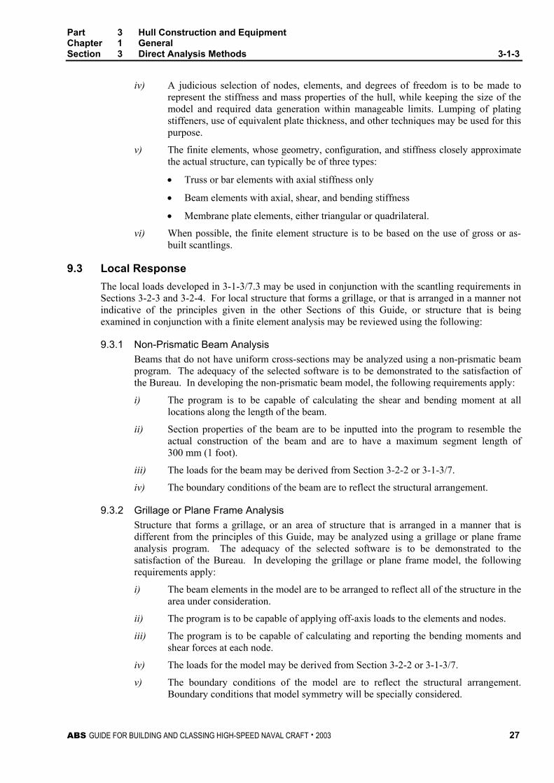
iv) A judicious selection of nodes, elements, and degrees of freedom is to be made to represent the stiffness and mass properties of the hull, while keeping the size of the model and required data generation within manageable limits. Lumping of plating stiffeners, use of equivalent plate thickness, and other techniques may be used for this purpose.
v) The finite elements, whose geometry, configuration, and stiffness closely approximate the actual structure, can typically be of three types:
• Truss or bar elements with axial stiffness only
• Beam elements with axial, shear, and bending stiffness
• Membrane plate elements, either triangular or quadrilateral.
vi) When possible, the finite element structure is to be based on the use of gross or as-built scantlings.
9.3 Local Response The local loads developed in 3-1-3/7.3 may be used in conjunction with the scantling requirements in Sections 3-2-3 and 3-2-4. For local structure that forms a grillage, or that is arranged in a manner not indicative of the principles given in the other Sections of this Guide, or structure that is being examined in conjunction with a finite element analysis may be reviewed using the following:
9.3.1 Non-Prismatic Beam Analysis Beams that do not have uniform cross-sections may be analyzed using a non-prismatic beam program. The adequacy of the selected software is to be demonstrated to the satisfaction of the Bureau. In developing the non-prismatic beam model, the following requirements apply:
i) The program is to be capable of calculating the shear and bending moment at all locations along the length of the beam.
ii) Section properties of the beam are to be inputted into the program to resemble the actual construction of the beam and are to have a maximum segment length of 300 mm (1 foot).
iii) The loads for the beam may be derived from Section 3-2-2 or 3-1-3/7.
iv) The boundary conditions of the beam are to reflect the structural arrangement.
9.3.2 Grillage or Plane Frame Analysis Structure that forms a grillage, or an area of structure that is arranged in a manner that is different from the principles of this Guide, may be analyzed using a grillage or plane frame analysis program. The adequacy of the selected software is to be demonstrated to the satisfaction of the Bureau. In developing the grillage or plane frame model, the following requirements apply:
i) The beam elements in the model are to be arranged to reflect all of the structure in the area under consideration.
ii) The program is to be capable of applying off-axis loads to the elements and nodes.
iii) The program is to be capable of calculating and reporting the bending moments and shear forces at each node.
iv) The loads for the model may be derived from Section 3-2-2 or 3-1-3/7.
v) The boundary conditions of the model are to reflect the structural arrangement. Boundary conditions that model symmetry will be specially considered.

Part 3 Hull Construction and Equipment Chapter 1 General Section 3 Direct Analysis Methods 3-1-3
28 ABS GUIDE FOR BUILDING AND CLASSING HIGH-SPEED NAVAL CRAFT . 2003
9.3.3 Local Fine Mesh Model from Global 3-D Model Detailed local stresses are to be determined by fine mesh FEM analysis of local structures, based on the results of the global 3-D analysis.
The requirements for developing the 3-D coarse mesh global model in 3-1-3/9.3.4 are also applicable to the development of the 2-D fine-mesh models. In developing the 2-D fine mesh model, the following requirements apply:
i) The mesh size of the 2-D finite element model are to be determined by adequately modeling the stiffness of the individual structural members forming the local structure.
ii) In modeling a local transverse structure, the web plating is modeled by membrane plates, using both quadrilateral and triangular elements. Stiffeners on the web plating, such as panel breakers, tripping brackets, flat bar stiffeners, etc., and the face plates of the webs are modeled by rod elements of equivalent cross sectional areas. Where face plates on brackets are tapered at the ends, the area of the rod elements should be reduced accordingly. The out-of-plane hull girder plating (i.e., deck, side shell, bottom shell, girders, etc.) is also to be modeled by rod elements, using an appropriate effective width.
iii) The mesh size used should be adequate to represent the overall stiffness of the considered local structure as a whole, such that smooth stress distributions in the structure can be obtained.
iv) Finer meshes are to be used in the probable high stressed areas in order to obtain more accurate stress distributions for these areas. The use of a uniform mesh with smooth transition and with avoidance to abrupt changes in mesh sizes is recommended.
v) In laying out the mesh, the shapes of membrane elements created are to be as regular as possible. The aspect ratios of plate elements are to be kept within 2:1. Elements with an aspect ratio higher than 5:1 may be used for convenience of modeling in way of low stress areas, or areas of low interest.
vi) The grid line spacing and element sizes for the transverse section can be determined by the spacing of the longitudinals on the bottom shell, inner bottom, and topside tank. The grid lines can either be in line with the longitudinals, or for a finer mesh, an additional one division can be added between the longitudinal spacing.
vii) Cutout openings for longitudinals and access holes need not be considered in the 2-D models. This is also applies to all lightening holes or other small openings in the webs.
viii) The stiffeners, panel breakers, and ribs that prevent local buckling that are parallel to the principal direction of stress are to be included in the model.
Boundary displacements obtained from the 3-D global analysis are to be used as boundary conditions in the fine mesh analysis. As applicable, the fine mesh models are to include at least the following local structures:
• A number of transverse web frames
• Centerline longitudinal girder
• Side longitudinal girder
• Horizontal stringers of watertight transverse bulkhead
• Other areas of high stress indicated from the 3-D global analysis.

Part 3 Hull Construction and Equipment Chapter 1 General Section 3 Direct Analysis Methods 3-1-3
ABS GUIDE FOR BUILDING AND CLASSING HIGH-SPEED NAVAL CRAFT . 2003 29
Where the 3-D global analysis is not comprehensive enough to determine adequately the total stress in the longitudinal plating (e.g., deck and shell) and transverse bulkhead plating of the craft, additional analyses may be required. Such analyses may not require the performance of fine mesh FEM analysis, where the needed results can be provided by another acceptable method.
9.3.4 Local Fine Mesh Model without Global 3-D Model Structure that forms a grillage or an area of structure that is arranged in a manner different from the principles of the Guide may be analyzed using a local finite element model. The adequacy of the selected software is to be demonstrated to the satisfaction of the Bureau. In developing the local finite element model, the following requirements apply:
i) The requirements in 3-1-3/9.3.4 are to be applied as applicable.
ii) The loads for the model may be derived from Section 3-2-2 or 3-1-3/7.
iii) The boundary conditions of the model are to reflect the structural arrangement. Boundary conditions that model symmetry will be specially considered.
11 Structural Acceptability
11.1 Beam, Grillage, or Plane Frame Analysis The allowable bending stress for elements in beam, grillage or plane frame models is given in 3-2-4/Table 1 or 3-2-4/Table 2. The allowable shear stress for aluminum and steel elements is 0.5τy (0.75τy for bottom primary structures) where τy is the minimum shear yield strength of the material. For aluminum structure, τy is to be in the welded condition. The allowable shear stress for composite members is 0.4τu, where τu is the lesser of the ultimate shear strength in either the warp or fill of the web laminate.
11.3 Finite Element Analysis
11.3.1 General The adequacy of the finite element analysis results is to be assessed for the failure modes of material yielding and buckling. The requirements in this section are for steel, aluminum and FRP craft. The acceptance criteria for craft constructed of other materials will be specially considered.
11.3.2 Yielding For a plate element subjected to biaxial stress, a specific combination of stress components, rather than a single maximum normal stress component constitutes the limiting condition. In this regard, the total equivalent stress is to be based on the Hencky von-Mises criterion as the following equation:
σe = [σx2 + σy
2 – σxσy + 3τxy2]1/2
where
σx = normal stress in the x coordinate direction of the element
σy = normal stress in the y coordinate direction of the element
τxy = in-plane shearing stress

Part 3 Hull Construction and Equipment Chapter 1 General Section 3 Direct Analysis Methods 3-1-3
30 ABS GUIDE FOR BUILDING AND CLASSING HIGH-SPEED NAVAL CRAFT . 2003
The total equivalent stress (Hencky von-Mises stress) is to be less than or equal to the following design stress:
Steel: 0.95σy
Aluminum: 0.85σy
FRP: 0.37σu
where σy is the yield strength for steel structures or the welded yield strength for aluminum structure, and σu is the ultimate tensile or compressive strength of the laminate, whichever is less.
11.3.3 Buckling and Ultimate Strength Plate panels, stiffened panels and primary supporting members are to be checked against buckling and ultimate strength using the stresses obtained from the finite element analyses by the criteria in 5-1-5/5.3.1 and 5-1-5/5.3.2 of the ABS Rules for Building and Classing Steel Vessels.
Plate buckling between stiffeners in the elastic range is considered acceptable provided that the plate satisfies the ultimate strength requirements.
Plate panels and stiffened panels are subjected to loads due to hull girder bending and shear and water pressure. Combined loads include bi-axial compression/tension, edge shear and compression/tension, in-plane loads and lateral pressure. The effects of combined load components should be accounted for, and the interaction formulae for combined loads should be applied. Proper modifications to the buckling and ultimate strength criteria should be made, taking into account the differences in gross and net scantling.
The local stiffness and geometric proportions given in 5-1-A2/11 of the ABS Rules for Building and Classing Steel Vessels to limit local buckling failures are to be observed in highly stressed areas. The ABS Guide for Buckling and Ultimate Strength Assessment for Offshore Structures may be used for reference.

ABS GUIDE FOR BUILDING AND CLASSING HIGH-SPEED NAVAL CRAFT . 2003 31
P A R T
3 C H A P T E R 2 Hull Structures and Arrangements
CONTENTS SECTION 1 Primary Hull Strength ..........................................................43
1 Longitudinal Hull Girder Strength – Monohulls ....................43 1.1 Section Modulus.............................................................. 43 1.3 Extension of Midship Section Modulus............................ 47 1.5 Moment of Inertia ............................................................ 48 1.7 Section Modulus and Moment of Inertia Calculation ....... 48 1.9 Hull Girder Shear Strength Calculation – For Craft
24 m (79 ft) in Length and Over ...................................... 49 1.11 Hull Girder Torsional Loads ............................................ 52
3 Primary Hull Strength – Twin-Hulled Craft...........................52 3.1 Longitudinal Hull Girder Strength .................................... 52 3.3 Catamaran Transverse Loadings .................................... 52 3.5 Transverse Strength for Catamarans and Surface
Effect Craft ...................................................................... 53 3.7 Items included in Transverse Moment of Inertia and
Section Modulus Calculation........................................... 53 3.9 Craft with More Than Two Hulls ...................................... 54 3.11 Hull Girder Torsional Loads ............................................ 54
5 Strength Considerations for Hydrofoil Borne Craft ..............54 5.1 Longitudinal Strength ...................................................... 54 5.3 Calculation of Loads from Hydrofoil Appendages ........... 54
7 Effective Decks ....................................................................55 9 Operating Manual ................................................................55 TABLE 1 Minimum Vertical Acceleration...................................46 TABLE 2 Factor, K.....................................................................48 FIGURE 1 Sign Convention.........................................................45 FIGURE 2 Distribution Factor M..................................................47 FIGURE 3 Distribution Factor F1 .................................................50 FIGURE 4 Distribution Factor F2 .................................................50

32 ABS GUIDE FOR BUILDING AND CLASSING HIGH-SPEED NAVAL CRAFT . 2003
SECTION 2 Design Pressures................................................................. 57 1 Monohulls.............................................................................57
1.1 Bottom Design Pressure..................................................57 1.3 Side and Transom Structure, Design Pressure ...............60
3 Multi-Hull and Surface Effect Craft ......................................62 3.1 Bottom Design Pressure..................................................62 3.3 Side and Transom Structure, Design Pressure ...............63 3.5 Wet Deck or Cross Structure...........................................64
5 Deck Design Pressures – All Craft ......................................64 7 Superstructures and Deckhouses – All Craft.......................64 9 Bulkhead Structure, Design Pressure – All Craft.................65
9.1 Tank Boundaries .............................................................65 9.3 Watertight Boundaries .....................................................66
11 Military Mission Loads..........................................................66 11.1 Loads Imposed Against Own-Craft Weapons Firing
Effects .............................................................................66 11.3 Human Loads ..................................................................68 11.5 Helicopter Decks .............................................................68 11.7 Masts...............................................................................69
TABLE 1 Design Significant Wave Heights, h1/3, and
Speeds, V...................................................................59 TABLE 2 Minimum Values for FD (L ≤ 24 m, 79 ft)....................60 TABLE 3 Values of a .................................................................65 TABLE 4 Deck Design Pressures, pd ........................................69 TABLE 5 Superstructures and Deckhouses Design
Pressures ...................................................................70 FIGURE 1 Deadrise, Flare, and Entry Angles.............................60 FIGURE 2..........................................................................................67 FIGURE 3..........................................................................................68 FIGURE 4 Decks, Superstructures, and Deckhouse
Pressures ...................................................................69 FIGURE 5 Decks, Superstructures, and Deckhouse
Pressures ...................................................................71 FIGURE 6 Design Area Factor FD ...............................................71 FIGURE 7 Vertical Acceleration Distribution Factor KV ...............72 FIGURE 8 Vertical Acceleration Distribution Factor FV ...............72 FIGURE 9 Wet Deck Pressure Distribution Factor FI..................73
SECTION 3 Plating................................................................................... 75
1 Aluminum or Steel................................................................75 1.1 General............................................................................75 1.3 Thickness ........................................................................75 1.5 Buckling Criteria ..............................................................78 1.7 Water Jet Tunnels and Transverse Thruster Tubes ........82 1.9 Decks Provided for the Operation or Stowage of
Vehicles...........................................................................82

ABS GUIDE FOR BUILDING AND CLASSING HIGH-SPEED NAVAL CRAFT . 2003 33
3 Aluminum Extruded Planking, Aluminum Sandwich Panels and Corrugated Panels............................................83 3.1 Aluminum Extruded Planking .......................................... 83 3.3 Aluminum Sandwich Panels............................................ 84 3.5 Corrugated Panels .......................................................... 85
5 Fiber Reinforced Plastic.......................................................85 5.1 General ........................................................................... 85 5.3 Fiber Reinforcement........................................................ 86 5.5 Single Skin Laminate ...................................................... 86 5.7 Sandwich Laminate......................................................... 89
7 Plating Subject to Military Mission Loads ............................93 TABLE 1 Aspect Ratio Coefficient for Isotropic Plates..............76 TABLE 2 Design Stress, σa, Aluminum and Steel.....................76 TABLE 3 Buckling Coefficients m1 and m2 .................................81 TABLE 4 Design Stresses for FRP, σa ......................................87 TABLE 5 Aspect Ratio Coefficient for Isotropic Plates.............88 TABLE 6 Coefficient v for FRP Sandwich Panels Shear
Strength......................................................................91 TABLE 7 Core Shear Design Strength......................................92 TABLE 8............................................................................................93 TABLE 9............................................................................................93 FIGURE 1 Values for β ................................................................83 FIGURE 2 Extruded Planking......................................................84
SECTION 4 Internals ................................................................................95
1 Aluminum and Steel.............................................................95 1.1 General ........................................................................... 95 1.3 Strength and Stiffness..................................................... 95 1.5 Elastic Buckling of Longitudinal Members....................... 97 1.7 Corrugated Panels ........................................................ 101 1.9 Web Thickness.............................................................. 102 1.11 Attachments .................................................................. 103 1.13 Direct Analysis Methods................................................ 103 1.15 Decks Exposed to Vehicle Loads.................................. 103
3 Fiber Reinforced Plastic.....................................................103 3.1 General ......................................................................... 103 3.3 Fiber Reinforcement...................................................... 104 3.5 Strength and Stiffness................................................... 104 3.7 Proportions.................................................................... 105 3.9 Buckling ........................................................................ 105
5 Stanchions .........................................................................105 5.1 General ......................................................................... 105 5.3 Stanchion Analysis........................................................ 105 5.5 Stanchion Load ............................................................. 106
34 ABS GUIDE FOR BUILDING AND CLASSING HIGH-SPEED NAVAL CRAFT . 2003
5.7 Permissible Load...........................................................106 5.9 FRP Stanchions ............................................................106 5.11 Support by Bulkheads ...................................................106
7 Internals Subject to Military Mission Loads........................107 TABLE 1 Design Stress, σa .......................................................96 TABLE 2 Maximum Stresses...................................................107 FIGURE 1 Transverse Side Frame .............................................96 FIGURE 2 Transverse Side Frame .............................................96 FIGURE 3 Corrugated Bulkhead ...............................................101 FIGURE 4 Corrugated Bulkhead End Connections ..................101
SECTION 5 Hull Structural Arrangement............................................. 109
1 Structural Arrangement – All Materials ..............................109 1.1 Framing, Webs, Girders, and Non-tight Structural
Bulkheads......................................................................109 1.3 Watertight Bulkheads ....................................................110 1.5 Tanks.............................................................................111 1.7 Decks ............................................................................111 1.9 Means of Escape...........................................................111 1.11 Double Bottoms.............................................................111 1.13 Door, Hatch, Scuttle, and Manhole Covers ...................112 1.15 Helicopter Landing Areas ..............................................112 1.17 Ammunition Stowage Magazines ..................................112 1.19 Arrangements for the Protection Against Own-Craft
Weapons-Firing Effects .................................................113
3 Structural Arrangements – Additional Requirements for Steel and Aluminum Alloys ................................................114 3.1 Shell Plating ..................................................................114
5 Structural Arrangements – Additional Requirements for Fiber Reinforced Plastic Hulls............................................114 5.1 Tanks.............................................................................114
SECTION 6 Arrangement, Structural Details and Connections......... 115
1 Structural Details................................................................115 1.1 Aluminum and Steel ......................................................115 1.3 Fiber Reinforced Plastic ................................................116
3 Welded and Mechanical Connections ...............................123 3.1 Steel and Aluminum ......................................................123 3.3 Fiber Reinforced Plastic ................................................123 3.5 Backing Bars and Tapping Plates .................................125
5 Deck-to-Hull Joints.............................................................125 5.1 Weather Joints ..............................................................125 5.3 Interior Joints.................................................................127

ABS GUIDE FOR BUILDING AND CLASSING HIGH-SPEED NAVAL CRAFT . 2003 35
7 Shell Details .......................................................................127 7.1 Keels ............................................................................. 127 7.3 Chines and Transoms ................................................... 128
TABLE 1 Deck-to-Hull Joints...................................................126 FIGURE 1 Piping or Opening through Foam Filled Space........117 FIGURE 2 Proportions of Stiffeners ..........................................118 FIGURE 3 Premolded FRP Form..............................................118 FIGURE 4 Premolded Stiffener .................................................118 FIGURE 5 Connection of Longitudinals to Transverses...........119 FIGURE 6 Engine Foundations .................................................120 FIGURE 7 Deck Fittings ............................................................121 FIGURE 8 Through Hull Penetration – Solid Laminate .............121 FIGURE 9 Through Hull Penetration – Sandwich Laminate .....122 FIGURE 10 Boundary Angles for FRP Components...................123 FIGURE 11a Plate Keel in One-piece Hull ....................................127 FIGURE 11b Plate Keel in Hull Molded in Halves.........................127 FIGURE 12 Vertical Keel or Skeg ...............................................128 FIGURE 13a Chine or Transom – Single Skin Construction.........128 FIGURE 13b Chine or Transom – Sandwich Construction ...........128 FIGURE 13c Stepped Chine – Foam Wedge Option....................129 FIGURE 13d Stepped Chine – Putty Radius.................................129
SECTION 7 Keels, Stems and Shaft Struts ..........................................131
1 Materials ............................................................................131 1.1 Ordinary Strength Steels............................................... 131 1.3 High Strength Steels and Aluminum Alloys................... 131 1.5 Fiber Reinforced Plastic ................................................ 131
3 Keels ..................................................................................132 3.1 Bar Keels ...................................................................... 132 3.3 Plate Keels.................................................................... 132
5 Stems.................................................................................132 5.1 Bar Stems ..................................................................... 132 5.3 Plate Stems................................................................... 132
7 Stern Frames .....................................................................133 9 Shaft Struts ........................................................................133
9.1 General ......................................................................... 133 9.3 V Strut ........................................................................... 133 9.5 I Strut ............................................................................ 133 9.7 Strut Length .................................................................. 134 9.9 Strut Barrel .................................................................... 134

36 ABS GUIDE FOR BUILDING AND CLASSING HIGH-SPEED NAVAL CRAFT . 2003
SECTION 8 Rudders .............................................................................. 135 1 General ..............................................................................135
1.1 Application.....................................................................135 1.3 Rudder and Rudder Stock Materials .............................135 1.5 Expected Torque ...........................................................135
3 Design Loads .....................................................................136 3.1 Rudder Force ................................................................136 3.3 Rudder Torque for Scantlings........................................137
5 Rudder Stocks ...................................................................138 5.1 Upper Rudder Stocks ....................................................138 5.3 Lower Rudder Stocks ....................................................138 5.5 Bending Moments .........................................................138
7 Rudder Couplings ..............................................................139 7.1 Flange Couplings ..........................................................139 7.3 Tapered Stock Couplings ..............................................140 7.5 Keyless Couplings.........................................................140
9 Double Plate Rudder..........................................................141 9.1 Strength.........................................................................141 9.3 Rudder Plating...............................................................142
11 Single Plate Rudders .........................................................142 11.1 Mainpiece Diameter ......................................................142 11.3 Blade Thickness ............................................................143 11.5 Arms..............................................................................143
13 Shelled Rudder Blades ......................................................143 15 Rudder Stops .....................................................................143 17 Supporting and Anti-Lifting Arrangements.........................143
17.1 Rudder Stock Bearings..................................................143 17.3 Rudder Carrier and Anti Lifting Devices ........................144
TABLE 1 Bearing Pressure .....................................................144 FIGURE 1 Rudder .....................................................................137 FIGURE 2 Tapered Couplings...................................................141
SECTION 9 Protection of Deck Openings............................................ 145
1 General ..............................................................................145 3 Position of Deck Openings.................................................145 5 Hatchway Coamings, Companionway Sills and Access
Sills.....................................................................................145 5.1 Coaming and Sill Heights ..............................................145
7 Enclosed Superstructures..................................................146 7.1 Closing Appliances........................................................146 7.3 Sills of Access Openings ...............................................146 7.5 Means of Access ...........................................................146

ABS GUIDE FOR BUILDING AND CLASSING HIGH-SPEED NAVAL CRAFT . 2003 37
9 Hatchways Closed by Covers of Steel and Fitted with Gaskets and Clamping Devices.........................................147 9.1 Strength of Covers ........................................................ 147 9.3 Means for Securing Weathertightness .......................... 147 9.5 Flush Hatch Covers....................................................... 147
11 Hatchways Closed by Portable Covers in Lower Decks or within Fully Enclosed Superstructures...........................148 11.1 General ......................................................................... 148 11.3 Steel Covers ................................................................. 148 11.5 Wheel Loading .............................................................. 148
13 Hatchways Closed by Covers of Materials Other Than Steel ...................................................................................148
14 Small Hatches on the Exposed Fore Deck........................148 14.1 Application .................................................................... 148 14.3 Strength ........................................................................ 149 14.5 Primary Securing Devices............................................. 149 14.7 Requirements for Primary Securing .............................. 149 14.9 Secondary Devices ....................................................... 150
15 Hatchways within Open Superstructures...........................152 17 Hatchways within Deckhouses ..........................................152 19 Machinery Casings ............................................................153
19.1 Arrangement ................................................................. 153 19.3 Scantlings ..................................................................... 153
21 Miscellaneous Openings in Freeboard and Superstructure Decks ........................................................153 21.1 Manholes and Scuttles.................................................. 153 21.3 Other Openings............................................................. 153 21.5 Escape Openings.......................................................... 153 21.7 Chain Pipe Opening ...................................................... 153
TABLE 1 Coamings and Sill Heights.......................................145 TABLE 2 Scantlings for Small Steel Hatch Covers on the
Fore Deck.................................................................150 FIGURE 1 Arrangement of Stiffeners ........................................151 FIGURE 2 Example of Primary Securing Method .....................152
SECTION 10 Protection of Shell Openings............................................155
1 Cargo, Gangway, or Fueling Ports ....................................155 1.1 Construction.................................................................. 155 1.3 Location ........................................................................ 155
3 Bow Doors, Inner Doors, Side Shell Doors and Stern Doors .................................................................................155 3.1 General ......................................................................... 155 3.3 Arrangement ................................................................. 155

38 ABS GUIDE FOR BUILDING AND CLASSING HIGH-SPEED NAVAL CRAFT . 2003
5 Securing, Locking and Supporting of Doors ......................156 5.1 Definitions......................................................................156
7 Securing and Supporting Devices .....................................156 7.1 General..........................................................................156 7.3 Bow Doors.....................................................................156 7.5 Side Shell and Stern Doors ...........................................157
9 Securing and Locking Arrangement ..................................157 9.1 General..........................................................................157 9.3 Operation.......................................................................157 9.5 Indication/Monitoring .....................................................158
11 Tightness ...........................................................................158 11.1 Bow Doors.....................................................................158 11.3 Inner Doors....................................................................158 11.5 Side Shell and Stern Doors ...........................................158
13 Bow Door Scantlings..........................................................159 13.1 General..........................................................................159 13.3 Primary Structure ..........................................................159 13.5 Secondary Stiffeners .....................................................159 13.7 Plating ...........................................................................159 13.9 Securing and Supporting Devices .................................159 13.11 Visor Door Lifting Arms and Supports ...........................160
15 Inner Door Scantlings ........................................................160 15.1 General..........................................................................160 15.3 Primary Structure ..........................................................160 15.5 Securing and Supporting Devices .................................160
17 Side Shell Door and Stern Door Scantlings.......................161 17.1 General..........................................................................161 17.3 Primary Structure ..........................................................161 17.5 Secondary Stiffeners .....................................................161 17.7 Plating ...........................................................................161 17.9 Securing and Supporting Devices .................................161
19 Bow Door Design Loads ....................................................162 19.1 External Pressure..........................................................162 19.3 External Forces .............................................................163 19.5 Visor Door Forces, Moments and Load Cases..............164 19.7 Side-Opening Door Load Cases....................................166
21 Inner Door Design Loads...................................................166 21.1 External Pressure..........................................................166 21.3 Internal Pressure ...........................................................166
23 Side Shell and Stern Doors................................................166 23.1 Design Forces for Primary Members.............................166 23.3 Design Forces for Securing or Supporting Devices of
Doors Opening Inwards.................................................166 23.5 Design Forces for Securing or Supporting Devices of
Doors Opening Outwards ..............................................167
ABS GUIDE FOR BUILDING AND CLASSING HIGH-SPEED NAVAL CRAFT . 2003 39
25 Allowable Stresses.............................................................168 25.1 Primary Structure and Securing and Supporting
Devices ......................................................................... 168 25.3 Steel Securing and Supporting Devices Bearing
Stress............................................................................ 168 25.5 Tensile Stress on Threaded Bolts ................................. 168
27 Operating and Maintenance Manual..................................168 27.1 Manual .......................................................................... 168 27.3 Operating Procedures ................................................... 168
FIGURE 1 Entry and Flare Angles ............................................162 FIGURE 2 Definition of αm and βm .............................................164 FIGURE 3 Visor Type Bow Door ...............................................165
SECTION 11 Bulwarks, Rails, Ports, Portlights, Windows,
Ventilators, Tank Vents and Overflows............................169 1 Bulwarks and Guard Rails .................................................169
1.1 Location and Heights .................................................... 169 1.3 Strength of Bulwarks ..................................................... 169 1.5 Arrangements of Guard Rails........................................ 169 1.7 Life Lines....................................................................... 170
3 Freeing Ports .....................................................................170 3.1 Basic Area..................................................................... 170 3.3 Trunks, Deckhouses and Hatchway Coamings............. 170 3.5 Superstructure Decks.................................................... 171 3.7 Open Superstructures ................................................... 171 3.9 Details of Freeing Ports................................................. 171
5 Portlights ............................................................................171 5.1 Construction.................................................................. 171 5.3 Testing .......................................................................... 172
7 Windows ............................................................................172 7.1 Construction.................................................................. 172 7.3 Testing .......................................................................... 174
9 Ventilators, Tank Vents and Overflows..............................174 9.1 General ......................................................................... 174 9.3 Ventilators ..................................................................... 174 9.5 Tank Vents and Overflows ............................................ 175 9.7 Ventilators, Tank Vents and Overflows on the Fore
Deck.............................................................................. 175 TABLE 1 Thickness of Tempered or Toughened Monolithic
Glass Portlights........................................................172 TABLE 2..........................................................................................173 TABLE 3..........................................................................................174 TABLE 4 760 mm (30 in.) High Tank Vents and Overflows
Thickness and Bracket Standards ...........................177 TABLE 5 900 mm (35.4 in.) High Ventilator Thickness and
Bracket Standards ...................................................177

40 ABS GUIDE FOR BUILDING AND CLASSING HIGH-SPEED NAVAL CRAFT . 2003
SECTION 12 Protective Coatings ........................................................... 179 1 General ..............................................................................179 3 Preparation ........................................................................179 5 Protection of Steel..............................................................179
5.1 Preparation....................................................................179 5.3 All Spaces .....................................................................179 5.5 Salt Water Ballast Space...............................................179 5.7 Oil Spaces .....................................................................180
7 Protection of Aluminum......................................................180 7.1 General..........................................................................180 7.3 Preparation....................................................................180 7.5 Coatings ........................................................................180 7.7 Faying Surfaces – Aluminum to Aluminum....................180 7.9 Faying Surface between Aluminum and Other
Metals............................................................................180 7.11 Faying Surface between Aluminum and Non-metals.....181 7.13 Corrosion of Wet Spaces...............................................181 7.15 Service at Elevated Temperatures ................................181 7.17 Cathodic Protection for Corrosion Prevention ...............181 7.19 Stray Current Protection ................................................181 7.21 Bi-material Joints...........................................................182
9 Protection of Fiber Reinforced Plastic ...............................182 9.1 General..........................................................................182 9.3 Preparation....................................................................182 9.5 Tanks.............................................................................182 9.7 Cathodic Protection .......................................................182
SECTION 13 Welding, Forming and Weld Design................................. 183
1 Fillet Welds ........................................................................183 1.1 General..........................................................................183 1.3 Tee Connections ...........................................................183 1.5 Fillet Sizes and Spacing ................................................183 1.7 Thin Plating ...................................................................184 1.9 Length and Arrangement of fillet ...................................184 1.11 Fillet Weld Arrangements ..............................................184
3 Bi-material Joints ...............................................................185 5 Alternatives ........................................................................185 TABLE 1 Weld Factor C ..........................................................186 FIGURE 1........................................................................................185

ABS GUIDE FOR BUILDING AND CLASSING HIGH-SPEED NAVAL CRAFT . 2003 41
APPENDIX 1 Guidelines for Calculating Bending Moment and Shear Force in Rudders and Rudder Stocks..............................187 1 Application .........................................................................187 3 Spade Rudders ..................................................................187
3.1 Rudder .......................................................................... 187 3.3 Lower Stock .................................................................. 188 3.5 Moment at Top of Upper Stock Taper ........................... 188 3.7 Bearing Reaction Forces............................................... 189
FIGURE 1 Spade Rudder..........................................................189
APPENDIX 2 Guidance on Analysis of the Cross Deck Structure of
a Multi-Hull Craft ................................................................191 1 Transverse Bending and Shear Stress..............................191 3 Center of Torsional Rotation..............................................192 5 Maximum Bending Stress on Each Element .....................193
5.1 Deflection ...................................................................... 193 5.3 Bending Moment ........................................................... 193 5.5 Maximum Stress ........................................................... 193 5.7 Maximum Shear Stress on Each Element..................... 194
FIGURE 1 Typical Geometry of Centerline Section of Cross
Deck .........................................................................191 FIGURE 2 Span of Cross Structure...........................................192
APPENDIX 3 Alternative Method for the Determination of “V” Shaft
Strut Requirements............................................................195 1 General ..............................................................................195 3 Loads and Moments Acting on Strut..................................196 5 Required Section Modulus of Strut at the Barrel ...............196 7 Required Section Modulus of Strut at the Hull...................197 9 Requirements for Struts Constructed of Aluminum ...........197 FIGURE 1 Strut Dimensions......................................................195

This Page Intentionally Left Blank
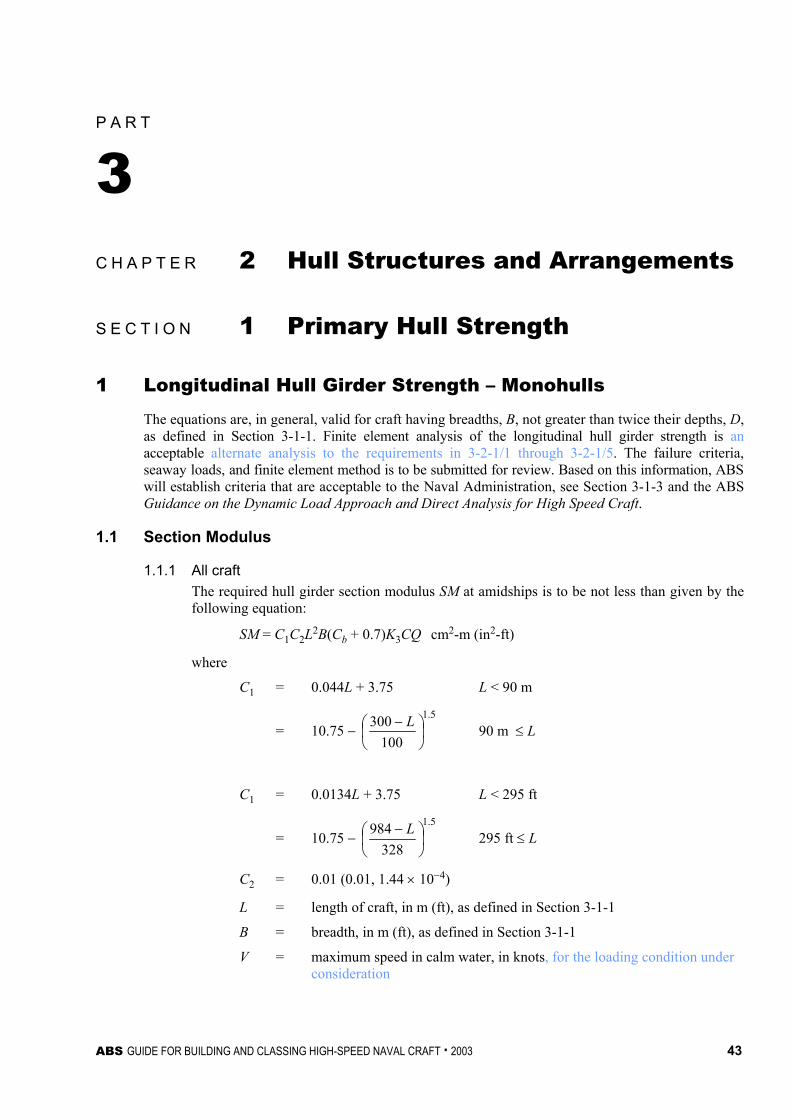
ABS GUIDE FOR BUILDING AND CLASSING HIGH-SPEED NAVAL CRAFT . 2003 43
P A R T
3 C H A P T E R 2 Hull Structures and Arrangements
S E C T I O N 1 Primary Hull Strength
1 Longitudinal Hull Girder Strength – Monohulls
The equations are, in general, valid for craft having breadths, B, not greater than twice their depths, D, as defined in Section 3-1-1. Finite element analysis of the longitudinal hull girder strength is an acceptable alternate analysis to the requirements in 3-2-1/1 through 3-2-1/5. The failure criteria, seaway loads, and finite element method is to be submitted for review. Based on this information, ABS will establish criteria that are acceptable to the Naval Administration, see Section 3-1-3 and the ABS Guidance on the Dynamic Load Approach and Direct Analysis for High Speed Craft.
1.1 Section Modulus
1.1.1 All craft The required hull girder section modulus SM at amidships is to be not less than given by the following equation:
SM = C1C2L2B(Cb + 0.7)K3CQ cm2-m (in2-ft)
where
C1 = 0.044L + 3.75 L < 90 m
= 10.75 − 5.1
100300
− L 90 m ≤ L
C1 = 0.0134L + 3.75 L < 295 ft
= 10.75 − 5.1
328984
− L 295 ft ≤ L
C2 = 0.01 (0.01, 1.44 × 10⁻⁴)
L = length of craft, in m (ft), as defined in Section 3-1-1
B = breadth, in m (ft), as defined in Section 3-1-1
V = maximum speed in calm water, in knots, for the loading condition under consideration
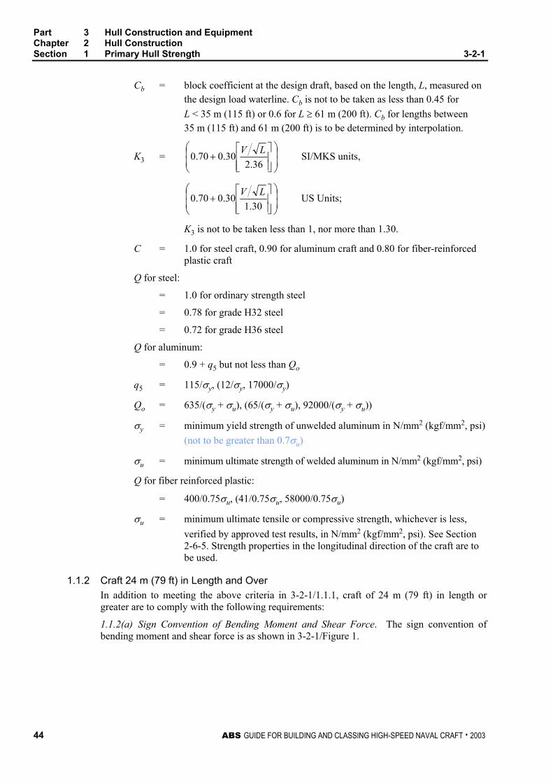
Part 3 Hull Construction and Equipment Chapter 2 Hull Construction Section 1 Primary Hull Strength 3-2-1
44 ABS GUIDE FOR BUILDING AND CLASSING HIGH-SPEED NAVAL CRAFT . 2003
Cb = block coefficient at the design draft, based on the length, L, measured on the design load waterline. Cb is not to be taken as less than 0.45 for L < 35 m (115 ft) or 0.6 for L ≥ 61 m (200 ft). Cb for lengths between 35 m (115 ft) and 61 m (200 ft) is to be determined by interpolation.
K3 =
+
36.230.070.0 LV SI/MKS units,
+
30.130.070.0 LV US Units;
K3 is not to be taken less than 1, nor more than 1.30.
C = 1.0 for steel craft, 0.90 for aluminum craft and 0.80 for fiber-reinforced plastic craft
Q for steel:
= 1.0 for ordinary strength steel
= 0.78 for grade H32 steel
= 0.72 for grade H36 steel
Q for aluminum:
= 0.9 + q5 but not less than Qo
q5 = 115/σy, (12/σy, 17000/σy)
Qo = 635/(σy + σu), (65/(σy + σu), 92000/(σy + σu))
σy = minimum yield strength of unwelded aluminum in N/mm2 (kgf/mm2, psi) (not to be greater than 0.7σu)
σu = minimum ultimate strength of welded aluminum in N/mm2 (kgf/mm2, psi)
Q for fiber reinforced plastic:
= 400/0.75σu, (41/0.75σu, 58000/0.75σu)
σu = minimum ultimate tensile or compressive strength, whichever is less, verified by approved test results, in N/mm2 (kgf/mm2, psi). See Section 2-6-5. Strength properties in the longitudinal direction of the craft are to be used.
1.1.2 Craft 24 m (79 ft) in Length and Over In addition to meeting the above criteria in 3-2-1/1.1.1, craft of 24 m (79 ft) in length or greater are to comply with the following requirements:
1.1.2(a) Sign Convention of Bending Moment and Shear Force. The sign convention of bending moment and shear force is as shown in 3-2-1/Figure 1.

Part 3 Hull Construction and Equipment Chapter 2 Hull Construction Section 1 Primary Hull Strength 3-2-1
ABS GUIDE FOR BUILDING AND CLASSING HIGH-SPEED NAVAL CRAFT . 2003 45
FIGURE 1 Sign Convention
(+)
(+)
FSW, FW
MSW, MW
Aft Fore
1.1.2(b) Wave Bending Moment Amidships. The wave bending moment, expressed in kN-m (tf-m, Ltf-ft), may be obtained from the following equations:
Mws = −k1C1L2B(Cb + 0.7) × 10−3 Sagging Moment
Mwh = +k2C1L2BCb × 10−3 Hogging Moment
where
k1 = 110 (11.22, 1.026)
k2 = 190 (19.37, 1.772)
C1, L, B and Cb are as defined in 3-2-1/1.1.1.
1.1.2(c) Still Water Bending Moment. The maximum still water bending moment in both the hogging and sagging condition is to be submitted. In case the detailed information is not available in the early stages of design, or the still water bending moment is not required to be submitted, the still water bending moment in kN-m (Ltf-ft) can be determined by the following:
Msws = 0 Sagging Moment
Mswh = 0.375fpC1C2L2B(Cb + 0.7) Hogging Moment
where
fp = 17.5 kN/cm2, (1.784 tf/cm2, 11.33 Ltf/in2)
C1, C2, L, B, Cb are as defined in 3-2-1/1.1.
1.1.2(d) Slamming Induced Bending Moment. The slamming induced bending moment in kN-m (Ltf-ft) can be determined by the following equation:
Msl = C3∆(1 + ncg)(L – ls) kN-m (tf-m, Ltf-ft)
where
C3 = 1.25 (0.125, 0.125)
∆ = full load displacement, in metric tons (long tons)

Part 3 Hull Construction and Equipment Chapter 2 Hull Construction Section 1 Primary Hull Strength 3-2-1
46 ABS GUIDE FOR BUILDING AND CLASSING HIGH-SPEED NAVAL CRAFT . 2003
ls = length of slam load, in m (ft)
= AR/Bwl
AR = 0.697∆/d m2 (25∆/d ft2)
Bwl = waterline breadth at the LCG, in m (ft)
ncg = maximum vertical acceleration as defined in 3-2-2/1.1, but (1 + ncg) is not to be taken less than indicated in 3-2-1/Table 1.
L is as defined in 3-2-1/1.1.1.
TABLE 1 Minimum Vertical Acceleration
∆ (metric tons, long tons) Minimum Vertical Acceleration, (ncg + 1) (g)
180 (177) 3 400 (394) 2
≥1200 (1181) 1
Note: Intermediate values of ncg are to be determined by interpolation.
1.1.2(e) Section Modulus. The required hull-girder section modulus for 0.4L amidships is to be obtained from the following equation:
p
tfCQMSM = cm2-m (in2-ft)
where
Mt = maximum total bending moment. To be taken as the greatest of the following:
= Mswh + Mwh
= –Msws – Mws
= Msl
Mswh = maximum still-water bending moment in the hogging condition, in kN-m (tf-m,Ltf-ft), as determined in 3-2-1/1.1.2(c).
Msws = maximum still water bending moment in the sagging condition, in kN-m (tf-m, Ltf-ft), as determined in 3-2-1/1.1.2(c).
Mwh = maximum wave induced bending moment in the hogging condition, in kN-m (tf-m, Ltf-ft), as determined in 3-2-1/1.1.2(b).
Mws = maximum wave induced bending moment in the sagging condition, in kN-m (tf-m, Ltf-ft), as determined in 3-2-1/1.1.2(b).
Msl = maximum slamming induced bending moment, in kN-m (tf-m, Ltf-ft), as determined in 3-2-1/1.1.2(d).
fp = 17.5 kN/cm2, (1.784 tf/cm2, 11.33 Ltf/in2)
C and Q are as defined in 3-2-1/1.1.1.
Consideration may be given to a seakeeping analysis based on craft speed and sea state to determine Mws and Mwh.
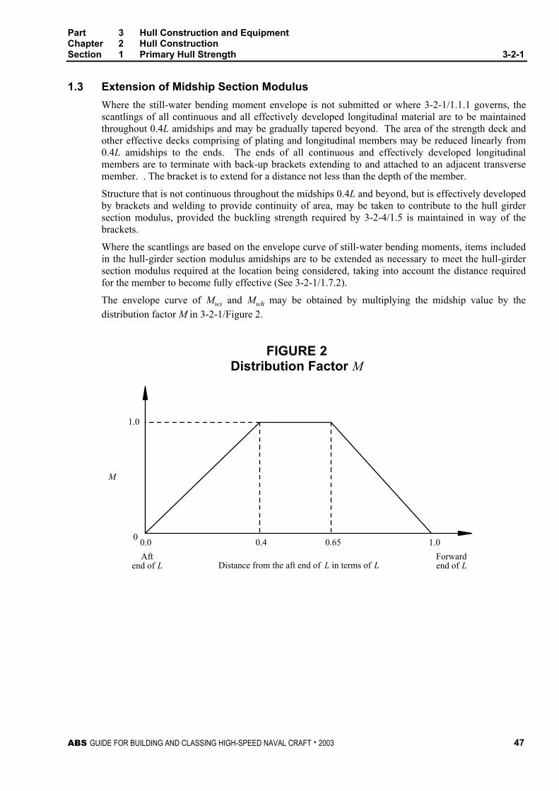
Part 3 Hull Construction and Equipment Chapter 2 Hull Construction Section 1 Primary Hull Strength 3-2-1
ABS GUIDE FOR BUILDING AND CLASSING HIGH-SPEED NAVAL CRAFT . 2003 47
1.3 Extension of Midship Section Modulus Where the still-water bending moment envelope is not submitted or where 3-2-1/1.1.1 governs, the scantlings of all continuous and all effectively developed longitudinal material are to be maintained throughout 0.4L amidships and may be gradually tapered beyond. The area of the strength deck and other effective decks comprising of plating and longitudinal members may be reduced linearly from 0.4L amidships to the ends. The ends of all continuous and effectively developed longitudinal members are to terminate with back-up brackets extending to and attached to an adjacent transverse member. . The bracket is to extend for a distance not less than the depth of the member.
Structure that is not continuous throughout the midships 0.4L and beyond, but is effectively developed by brackets and welding to provide continuity of area, may be taken to contribute to the hull girder section modulus, provided the buckling strength required by 3-2-4/1.5 is maintained in way of the brackets.
Where the scantlings are based on the envelope curve of still-water bending moments, items included in the hull-girder section modulus amidships are to be extended as necessary to meet the hull-girder section modulus required at the location being considered, taking into account the distance required for the member to become fully effective (See 3-2-1/1.7.2).
The envelope curve of Mws and Mwh may be obtained by multiplying the midship value by the distribution factor M in 3-2-1/Figure 2.
FIGURE 2 Distribution Factor M
0
M
Aftend of L
Forwardend of L
0.4 0.65 1.00.0
1.0
Distance from the aft end of L in terms of L

Part 3 Hull Construction and Equipment Chapter 2 Hull Construction Section 1 Primary Hull Strength 3-2-1
48 ABS GUIDE FOR BUILDING AND CLASSING HIGH-SPEED NAVAL CRAFT . 2003
1.5 Moment of Inertia The hull-girder moment of inertia, I, at amidships is to be not less than given by the following equation:
KSM
QCLI = cm2-m2 (in2-ft2)
where
SM = required hull-girder section modulus in 3-2-1/1.1.1 or 3-2-1/1.1.2, whichever is greater, in cm2-m (in2-ft)
K = factor dependent on the material and craft length as given in 3-2-1/Table 2 below
L, C and Q are as defined in 3-2-1/1.1.1.
TABLE 2 Factor, K
L (m, ft) Steel Aluminum FRP (Basic Laminate)
10 (33) 10.89 3.63 0.36 30 (100) 16.50 5.50 0.55 50 (165) 22.10 7.37 0.74 70 (230) 27.40 9.13 0.91 90 (295) 33.00 11.00 1.10
Note: For fiber reinforced plastic laminates that are greater than the ABS basic laminate (as defined in Part 2, Section 6) the value for K can be adjusted by the ratio of Eo/Eb where:
Eo = the elastic modulus of the actual hull laminate in N/mm2
(kgf/mm2, psi)
Eb = 6890 N/mm2 (703 kgf/mm2, 1,000,000 psi)
1.7 Section Modulus and Moment of Inertia Calculation
1.7.1 Items Included in the Calculation In general, the following items may be included in the calculation of the section modulus and moment of inertia provided they are continuous or effectively developed within midship 0.4L, have adequate buckling strength, and are gradually tapered beyond the midship 0.4L.
• Deck plating (strength deck and other effective decks)
• Shell and inner bottom plating
• Deck and bottom girders
• Plating and longitudinal stiffeners of longitudinal bulkheads
• All longitudinals of deck, sides, bottom, and inner bottom
1.7.2 Effective Areas Included in the Calculation In general, the net sectional areas of longitudinal strength members are to be used in the hull girder section modulus calculations, except that small isolated openings need not be deducted provided the openings and the shadow area breadths of other openings in any one transverse section do not reduce the section modulus by more than 3%. The breadth or depth of such

Part 3 Hull Construction and Equipment Chapter 2 Hull Construction Section 1 Primary Hull Strength 3-2-1
ABS GUIDE FOR BUILDING AND CLASSING HIGH-SPEED NAVAL CRAFT . 2003 49
openings is not to be greater than 25% of the breadth or depth of the member in which it is located with a maximum of 75 mm (3 in.) for scallops. The shadow area of an opening is the area forward and aft of the opening enclosed by the lines tangential to the corners of the opening intersecting each other to form an included angle of 30 degrees.
1.7.3 Section Modulus to the Deck or Bottom The section modulus to the deck or bottom is obtained by dividing the moment of inertia by the distance from the neutral axis to the molded deck at side amidships or baseline, respectively. Where a long deckhouse or superstructure is considered as part of the hull girder, the section modulus to the deck is obtained by dividing the moment of inertia by the distance from the neutral axis to the top of the bulwark, deckhouse or superstructure.
1.7.4 Breaks Craft having partial superstructures are to be specially strengthened in way of breaks to limit the local increase in stresses at these locations. The main deck plate and side shell plate thickness is to be increased a minimum of 25%, but the increase need not exceed 6.5 mm (0.25 in.). This increase is to extend well beyond the break in both directions in such a fashion to provide a long gradual taper. Where breaks of the superstructure (e.g. long forecastle) are appreciably beyond the amidships 0.5L, these requirements may be modified. Gangways, large freeing ports and other openings in the shell or bulwarks are to be kept well clear of breaks, and any holes which must be unavoidably be cut in the plating are to be kept as small as possible and are to be circular or oval in form.
1.9 Hull Girder Shear Strength Calculation – For Craft 24 m (79 ft) in Length and Over
1.9.1 General The nominal total shear stresses due to still-water and wave-induced loads are to be based on the maximum algebraic sum of the shear force in still-water, Fsw, the wave-indicated shear force, Fw, and the slam induced shear force, Fsl, at the location being considered. The thickness of the side shell is to be such that the nominal total shear stress as obtained by 3-2-1/1.9.3 are not greater than 11.0/Q kN/cm2 (1.122/Q tf/cm2, 7.122/Q Ltf/in2) where Q is as defined in 3-2-1/1.1.1. Consideration is also to be given to the shear buckling strength of the side shell plating.
1.9.2 Wave Shear Forces The envelopes of maximum shearing forces induced by waves, Fw, as shown in 3-2-1/Figures 3 and 4 may be obtained from the following equations:
Fwp = +kF1C1LB(Cb + 0.7) × 10−2 For positive shear force
Fwn = −kF2C1LB(Cb + 0.7) × 10−2 For negative shear force
where
Fwp, Fwn = maximum shearing force induced by wave, in kN (tf, Ltf)
k = 30 (3.059, 0.2797)
F1 = distribution factor as shown in 3-2-1/Figure 3
F2 = distribution factor as shown in 3-2-1/Figure 4
C1, L, B and Cb are as defined in 3-2-1/1.1.1.

Part 3 Hull Construction and Equipment Chapter 2 Hull Construction Section 1 Primary Hull Strength 3-2-1
50 ABS GUIDE FOR BUILDING AND CLASSING HIGH-SPEED NAVAL CRAFT . 2003
FIGURE 3 Distribution Factor F1
0
Aftend of L
Forwardend of L
0.92 X 190 Cb
110 (Cb + 0.7)
1.0
0.7F1
0.0 0.2 0.3 0.4 0.6 0.7 0.85 1.0
Distance from the aft end of L in terms of L
FIGURE 4 Distribution Factor F2
0
Aftend of L
Forwardend of L
190 Cb
110 (Cb + 0.7)
0.92
F2
Distance from the aft end of L in terms of L
0.7
0.0 0.2 0.3 0.4 0.6 0.7 0.85 1.0
Part 3 Hull Construction and Equipment Chapter 2 Hull Construction Section 1 Primary Hull Strength 3-2-1
ABS GUIDE FOR BUILDING AND CLASSING HIGH-SPEED NAVAL CRAFT . 2003 51
1.9.3 Slam Induced Shear Force. The slamming induced shear force can be determined by the following equation:
Fsl = C4∆(ncg + 1) kN (tf, Ltf)
C4 = 4.9 (0.5)
∆ = full load displacement in metric tons (long tons)
ncg = maximum vertical acceleration as defined in 3-2-2/1.1
1.9.4 Shear Strength For craft without continuous longitudinal bulkheads, the nominal total shear stress fs in the side shell plating may be obtained from the greater of the following equations:
fs = (Fsw + Fw )m/2tsI
fs = Fsl m/2tsI
where
fs = nominal total shear stress, in kN/cm2 (tf/cm2, Ltf/in2)
I = moment of inertia of the hull girder section, in cm4 (in4), at the section under consideration
m = first moment about the neutral axis, of the area of the effective longitudinal material between the horizontal level at which the shear stress is being determined and the vertical extremity of effective longitudinal material, taken at the section under consideration, in cm3 (in3)
ts = thickness of the side shell plating, at the position under consideration, in cm (in.)
Fsw = hull-girder shearing force in still-water, in kN (tf, Ltf)
Fw = Fwp or Fwn as specified by 3-2-1/1.9.2, depending upon loading
Fsl = slam induced shear force, in kN (Ltf), as indicated in 3-2-1/1.9.3. The slam induced shear force is to be applied in both the hogging and sagging conditions
1.9.5 Shearing Strength for Craft with Two or Three Longitudinal Bulkheads For craft having continuous longitudinal bulkheads the total shear stresses in the side shell and longitudinal bulkhead plating are to be calculated by an acceptable method. In determining the still-water shear force, consideration is to be given to the effect of non-uniform athwartship distribution of loads. The methods described in Appendix 3-2-A1 of the Rules for Building and Classing Steel Vessels may be used as a guide in calculating the nominal total shear stress fs related to the shear flow in the side shell or longitudinal bulkhead plating. Alternative methods of calculation will also be considered. One acceptable method is shown in Appendix 5-2-A1 of the Rules for Building and Classing Steel Vessels.
1.9.6 Hull Girder Shear Strength – FRP Craft Hull girder shear strength will be specially considered on fiber reinforced plastic craft over 24 m (79 ft) in length.
1.9.7 Craft of Unusual Proportion Craft having unusual proportions will be specially considered.

Part 3 Hull Construction and Equipment Chapter 2 Hull Construction Section 1 Primary Hull Strength 3-2-1
52 ABS GUIDE FOR BUILDING AND CLASSING HIGH-SPEED NAVAL CRAFT . 2003
1.11 Hull Girder Torsional Loads Torsional calculations may be required for craft with large deck openings. Racking load calculations may be required for craft with tall superstructures.
3 Primary Hull Strength – Twin-Hulled Craft
3.1 Longitudinal Hull Girder Strength The following applies to catamarans, surface effect craft, and similar configuration twin hulled craft.
The longitudinal strength requirements for twin-hulled craft are as given in 3-2-1/1.1, with the following modifications:
i) B is to be taken as the sum of the waterline breadths of each hull.
ii) For craft less than 24 m (79 ft), longitudinal shear strength need not be considered unless they have unusual or highly concentrated loads. For craft over 24 m (79 ft) the shear strength will be specially considered.
iii) Items as listed in 3-2-1/1.7 may be included in the longitudinal strength calculation for the total cross section of the hulls, with the addition of the cross deck bridging structure. Consideration is to be given to the length over which the cross-deck structure becomes fully effective.
3.3 Catamaran Transverse Loadings The transverse primary hull loadings are determined by the following equations:
Mtb = K1∆Bcl (1 + ncg) kN-m (kgf-m, ft-lbs)
Mtt = K2∆L(1 + ncg) kN-m (kgf-m, ft-lbs)
Qt = K1∆(1 + ncg) kN (kgf, lbs)
where
Mtb = design transverse bending moment acting upon the cross structure connecting the hulls
Mtt = design torsional moment acting upon the transverse structure connecting the hulls
Qt = design vertical shear force acting upon the transverse structure connecting the hulls
K1 = 2.5 (0.255, 0.255)
K2 = 1.25 (0.1275, 0.1275)
∆ = craft displacement in tonnes (kg, lbs).
Bcl = distance between the hull centerlines, in meters (feet)
L = length of craft, in meters (feet), as defined in 3-1-1/3.
ncg = vertical acceleration at the craft’s center of gravity, see 3-2-2/1.1, but (1 + ncg) is not to be taken less than indicated in 3-2-1/Table 1.
Part 3 Hull Construction and Equipment Chapter 2 Hull Construction Section 1 Primary Hull Strength 3-2-1
ABS GUIDE FOR BUILDING AND CLASSING HIGH-SPEED NAVAL CRAFT . 2003 53
3.5 Transverse Strength for Catamarans and Surface Effect Craft
3.5.1 Direct Analysis The design loads that are to be applied to the structure are the transverse bending moment, Mtb, the torsional moment, Mtt, and vertical shear force, Qt, as defined in 3-2-1/3.5 and the longitudinal bending moments as given in 3-2-1/1.1.2. The requirements for the direct analysis are given in Section 3-1-3.
3.5.2 Analysis for Simple Structures Guidance for the analysis of cross deck structures that are symmetrical forward and aft of a transverse axis at amidships can be found in Appendix 3-2-A2.
3.5.3 Design Stresses and Deflections Regardless of the method of analysis used, the design stresses are as follows:
σa = design transverse bending stress, 0.66σy for aluminum and steel craft and 0.33σu for FRP craft, in N/mm2 (kgf/mm2, psi)
σab = design torsional or combined stress, 0.75σy for aluminum and steel craft and 0.367σu for FRP craft, in N/mm2 (kgf/mm2, psi)
τa = design transverse shear stress, 0.38σy for aluminum and steel craft and 0.40τu for FRP craft, in N/mm2 (kgf/mm2, psi)
σy = minimum yield strength of the material, in N/mm2 (kgf/mm2, psi). For aluminum the yield strength is to be for the unwelded condition and not to be greater than 0.7σuw
σu = minimum tensile or compressive strength, whichever is less, in N/mm2 (kgf/mm2, psi)
σuw = ultimate tensile strength of material in the welded condition, in N/mm2 (kgf/mm2, psi)
δm = maximum deflection for FRP craft, (σa/E)LI, in m (in.)
τu = minimum ultimate through thickness shear strength, in N/mm2 (kgf/mm2, psi)
LI = mean span of cross structure, in cm (in.), as indicated in 3-2-A2/Figure 2
E = tensile or compressive modulus of the FRP laminate, whichever is lesser, in N/mm2 (kgf/mm2, psi)
3.7 Items included in Transverse Moment of Inertia and Section Modulus Calculation The following items may be included in the calculation of the transverse section modulus and moment of inertia provided that are continuous or effectively developed over the entire breadth of the cross structure or wet deck, and have adequate buckling strength:
• Deck plating, main deck and bottom plating of wet deck
• Transverse stiffeners on wet deck

Part 3 Hull Construction and Equipment Chapter 2 Hull Construction Section 1 Primary Hull Strength 3-2-1
54 ABS GUIDE FOR BUILDING AND CLASSING HIGH-SPEED NAVAL CRAFT . 2003
• Transverse bulkheads or web frames which span the wet deck, and are effectively developed into the hulls
• Transverse box beams, that are effectively developed into the hulls
• Continuous transom plating and attached horizontal stiffeners
In general, the effective sectional area of the deck for use in calculating the section modulus is to exclude hatchways and other large openings in the deck.
Superstructures and house tops are generally not to be included in the calculation of sectional properties of the cross structure. Craft having unusual configuration such as cross-deck structure out-of-line with the main hull structure will be specially considered.
3.9 Craft with More Than Two Hulls Transverse and torsional strength of craft with more than two hulls will be specially considered.
3.11 Hull Girder Torsional Loads Torsional calculations may be required for craft with large deck openings. Racking load calculations may be required for craft with high superstructures.
5 Strength Considerations for Hydrofoil Borne Craft
5.1 Longitudinal Strength The hull weight curve showing full load, lightship and partial load (if more severe) is to be submitted. The support reactions for each of the hydrofoils are to be shown. The resulting shear and bending moment diagrams, as derived from these curves, are to be submitted for approval.
Hull deflection under the condition of maximum bending moment is not to exceed 1/200 of the distance between the forward and aft foil attachment points.
5.3 Calculation of Loads from Hydrofoil Appendages The maximum forces transmitted by any hydrofoil to the craft structure is given by the following equations:
FL = CUCLV2AP
FD = CUV2 (CDF AFF + CDS AFS) + (Wetted surface drag)
where
FL = maximum lift force on craft exerted by hydrofoil, in kgf (lbs). This force is assumed to act perpendicular to the plane of the foil.
FD = maximum drag force on craft exerted by hydrofoil plus strut, in kgf (lbs). This force is assumed to act directly aft from the center of the foil.
CU = 13.847 (2.835)
CL = peak coefficient of lift for the foil selected.
CDF = peak coefficient of drag for the foil selected.
CDS = peak coefficient of drag for the strut section selected.
V = maximum craft speed, in knots.

Part 3 Hull Construction and Equipment Chapter 2 Hull Construction Section 1 Primary Hull Strength 3-2-1
ABS GUIDE FOR BUILDING AND CLASSING HIGH-SPEED NAVAL CRAFT . 2003 55
AP = plan view area of foil, in m2 (ft2)
AFF = frontal area of foil, in m2 (ft2)
AFS = frontal area of strut, in m2 (ft2)
Total drag of the foil and strut (or similar appendage) is given by the drag term FD that includes the frictional drag coefficient, as a function of wetted surface and Reynolds number.
The strength of the foils and struts are to be based on FL and FD and the resulting bending moments, shear forces, and vertical forces. The strength of the connections of the struts to the hull is to be based on the bending moments, shear forces, and vertical forces applied through the struts. A factor of safety on the yield strength of the material (aluminum use the as-welded condition) is to be not less than 2.0. Calculations of the bending moment, shear forces, and stiffness, are to be carried out and submitted by the designer.
Additionally, calculations supporting the “Fail-Safe” performance of each foil attachment structure are to be submitted.
Watertight integrity of the shell is to be maintained in the event of a collision of the hydrofoil appendages with a solid object in the water. A design safety factor of 2.0 on the yield strength or 3.0 on the ultimate strength of the foil strut bearing is to be used to assess the strength of the foil for the collision condition.
7 Effective Decks
To be considered effective for use in calculating the hull girder section modulus, the thickness of the deck plating is to comply with the requirements of Section 3-2-3. The deck areas are to be maintained throughout the midship 0.4L and may be gradually reduced to one half their midship value at 0.15L from the ends. Only that portion of deck which is continuous through the transverse structure may be considered effective.
9 Operating Manual
Craft are to be furnished with an operating manual providing guidance on:
i) Loading conditions on which the design of the craft has been based, including cargo loading on decks, loading ramps, and double bottoms.
ii) Permissible limits of still-water bending moments and shear forces, for craft 24 m (79 ft) in length or greater.
iii) Maximum operational speeds for the various sea-states (significant wave heights) in which the craft is intended to operate, in conjunction with the OE notation (see 1-1-3/5).

This Page Intentionally Left Blank

ABS GUIDE FOR BUILDING AND CLASSING HIGH-SPEED NAVAL CRAFT . 2003 57
P A R T
3 C H A P T E R 2 Hull Structures and Arrangements
S E C T I O N 2 Design Pressures
1 Monohulls
The bottom and side pressures are to be checked using the displacement (∆), speed (V), draft (d), and running trim (τ) in the full load, half load, and light load conditions. If the craft is receiving a freeboard assignment, the parameters used in the full load condition are to coincide with the assigned freeboard. If the craft is not receiving a freeboard assignment, the parameters used in the full load condition are to correspond to the condition of the craft with the maximum operating deadweight. The parameters used in the half load condition are to correspond to the condition of the craft with 50% of the maximum operating deadweight, and the parameters used in the light load condition are to correspond to the condition of the craft with 10% of the maximum operating deadweight plus the maximum speed of the craft.
1.1 Bottom Design Pressure The bottom design pressure is to be the greater of those, as given in the following equations, for the location under consideration. Bottom structure design pressures are dependent upon the service in which the craft operates. The bottom design pressure applies to hull bottoms below the chines or the upper turn of the bilge.
1.1.1 Bottom Slamming Pressure
Dcgww
bcg FnBL
Np ]1[1 +=∆ kN/m2 (tf/m2, psi)
Dcg
bxxx
wwbxx Fn
BLN
p
−−
+=ββ∆
7070
]1[1 kN/m2 (tf/m2, psi)
1.1.2 Bottom Slamming for Craft Less Than 61 meters (200 feet) The design pressure may be:
vDcgww
bxx FFnBL
Np ]1[1 +=∆ kN/m2 (tf/m2, psi)
1.1.3 Hydrostatic Pressure pd = N3 (0.64H + d) kN/m2 (tf/m2, psi)
Part 3 Hull Construction and Equipment Chapter 2 Hull Construction Section 2 Design Pressures 3-2-2
58 ABS GUIDE FOR BUILDING AND CLASSING HIGH-SPEED NAVAL CRAFT . 2003
where
pbcg = bottom design pressure at LCG, kN/m2 (tf/m2, psi)
pbxx = bottom design pressure at any section clear of LCG, kN/m2 (tf/m2, psi)
pd = bottom design pressure based on hydrostatic forces, kN/m2 (tf/m2, psi)
ncg = the vertical acceleration of the craft as determined by a model test, theoretical computation, or service experience (see Section 3-1-3). If this information is not readily available during the early stages of design, the following formula utilizing the average 1/100 highest vertical accelerations at LCG can be used:
ncg = [ ]∆
βτ22
3/12
)(500.112 wcg
w
BVBhN −
+ g’s
note that g’s are the dimensionless ratio of the acceleration at sea level (9.8m/s2, 32.2 ft/s2).
The vertical acceleration, ncg, is typically not to be taken greater than the following:
ncg = L
Vkn+39.1
for speeds greater than 18 L (9.94 L ) the maximum ncg is 6.0 g (7.0 g for search and rescue type craft). The vertical accelerations are typically not to be taken less than 1.0 g for craft lengths less than 24 m (79 ft) and 2.0 g for craft lengths less than 12 m (39 ft). Intermediate values can be determined by interpolation. The vertical acceleration will need to be specially considered for craft fitted with seat belts or special shock mitigation seats.
kn = 0.256 (0.463)
nxx = average of the 1/100 highest vertical accelerations, at any section clear of LCG, in g’s. Can be determined by the following equation:
= ncgKv
N1 = 0.1 (0.01, 0.069)
N2 = 0.0078 (0.0078, 0.0016)
N3 = 9.8 (1.0, 0.44)
∆ = displacement at design waterline, in kg (lbs), see 3-2-2/1
Lw = craft length on the waterline with the craft at the design displacement and in the displacement mode, in m (ft)
Bw = maximum waterline beam, in m (ft)
H = wave parameter, 0.0172L + 3.653 m (0.0172L + 11.98 ft), generally not to be taken less than the maximum survival wave height for the craft
h1/3 = significant wave height, m (ft), see 3-2-2/Table 1.

Part 3 Hull Construction and Equipment Chapter 2 Hull Construction Section 2 Design Pressures 3-2-2
ABS GUIDE FOR BUILDING AND CLASSING HIGH-SPEED NAVAL CRAFT . 2003 59
τ = running trim at V, in degrees, but generally not to be taken less than 4° for craft L < 50 m (165 ft), nor less than 3° for L > 50 m (165 ft). Special consideration will be given to designers values predicted from model tests.
βcg = deadrise at LCG, degrees, generally not to be taken less than 10° nor more than 30°.
βbx = deadrise at any section clear of LCG, in degrees, not to be taken less than 10° nor greater than 30°, see 3-2-2/Figure 1.
V = craft design speed in knots, see 3-2-2/Table 1
FD = design area factor given in 3-2-2/Figure 6 for given values of AD and AR. Generally not to be taken less than 0.4. See 3-2-2/Table 2 for minimum values of FD for craft less than 24 m (79 ft) in length.
Fv = vertical acceleration distribution factor given in 3-2-2/Figure 8.
KV = vertical acceleration distribution factor given in 3-2-2/Figure 7.
AD = design area, cm2 (in2). For plating it is the actual area of the shell plate panel but not to be taken as more than 2.5s2. For longitudinals, stiffeners, transverses and girders it is the shell area supported by the longitudinal stiffener, transverse or girder; for transverses and girders the area used need not be taken less than 0.33l2.
AR = reference area, cm2 (in2), 6.95∆/d cm2 (1.61∆/d in2).
s = spacing of longitudinals or stiffeners, in cm (in.)
l = unsupported span of internals, in cm (in.). See 3-2-4/1.3.1.
d = stationary draft, in m (ft), vertical distance from outer surface of shell measured at centerline to design waterline at middle of design waterline length, but generally not to be taken as less than 0.04L. See 3-2-2/1.
TABLE 1 Design Significant Wave Heights, h1/3, and Speeds, V
Operational Condition Survival Condition h1/3 V h1/3 V
Naval Craft 4 m (13 ft) Vm(2) 6 m (20 ft) (1) 10 knots (3)
Coastal Naval Craft 2.5 m (8.5 ft) Vm(2) 4 m (13 ft) 10 knots (3)
Riverine Naval Craft 0.5 m (1.75 ft) Vm(2) 1.25 m (4 ft) 10 knots (3)
Notes: 1 Not to be taken less than L/12
2 Vm = maximum speed for the craft in the design condition specified in 3-2-2/1
3 This speed is to be verified by the Naval Administration.

Part 3 Hull Construction and Equipment Chapter 2 Hull Construction Section 2 Design Pressures 3-2-2
60 ABS GUIDE FOR BUILDING AND CLASSING HIGH-SPEED NAVAL CRAFT . 2003
TABLE 2 Minimum Values for FD (L ≤ 24 m, 79 ft)
s mm (in.)
FD
250 (9.75) 0.85 500 (16.75) 0.75 750 (29.5) 0.60 1000 (39.25) 0.50 1250 (49.25) 0.40
FIGURE 1 Deadrise, Flare, and Entry Angles
TANGENT LINETANGENT LINE
β
βbx
βsx
βbx
βsx
α
1.3 Side and Transom Structure, Design Pressure The side design pressure, ps, is to be not less than given by the equations:
1.3.1 Slamming Pressure
Dcg
sxxx
wwsxx Fn
BLN
p
−−
+=ββ∆
7070
]1[1 kN/m2 (tf/m2, psi)

Part 3 Hull Construction and Equipment Chapter 2 Hull Construction Section 2 Design Pressures 3-2-2
ABS GUIDE FOR BUILDING AND CLASSING HIGH-SPEED NAVAL CRAFT . 2003 61
1.3.2 Hydrostatic Pressure ps = N3(Hs – y) kN/m2 (tf/m2, psi)
1.3.3 Fore End psf = 0.28FaCFN3(0.22 + 0.15tanα)(0.4Vsinβ + 0.6 L )2 kN/m2 (tf/m2)
psf = 0.92FaCFN3(0.22 + 0.15tanα)(0.4Vsinβ + 0.33 L )2 psi
where L is generally not to be taken less than 30 m (98 ft)
where
psxx = side design slamming pressure at any section clear of LCG, in kN/m2 (tf/m2, psi). For craft greater than 24 m (79 ft) in length, the side design slamming pressure only applies to locations below L/12 above baseline and forward of 0.125L
Design WaterlineBaseline
L/20 above Baseline
0.125L from Stem
ps = side design pressure due to hydrostatic forces, in kN/m2 (tf/m2, psi), but
is not to be taken less than the following:
= 0.05N3L kN/m2 (tf/m2, psi) at or below L/15 above the base line or any height above base line forward of 0.125L from the stem
= 0.033N3L kN/m2 (tf/m2, psi) above L/15 above the base line, aft of 0.125L from the stem
Psf = side design pressure for forward of 0.125L from the stem.
Hs = 0.083L + d in meters (feet), but it is not to be taken less than D + 1.22 (D + 4) for craft less than 30 m (100 ft)
= 0.64H + d in meters (feet) for craft over 30 m (100 ft); where H is defined in 3-2-2/1.1
y = distance above base line of location being considered, in m (ft)
L = craft length as defined in 3-1-1/3
βsx = deadrise of side at any section clear of LCG, in degrees, not to be taken greater than 55°, see 3-2-2/Figure 1
CF = 0.0125L for L < 80 m (0.00381L for L < 262 ft)
= 1.0 for L ≥ 80 m (262 ft)
Fa = 3.25 for plating and 1.0 for longitudinals, transverses and girders
α = flare angle, the angle between a vertical line and the tangent to the side shell plating, measured in a vertical plane at 90° to the horizontal tangent to the side shell, see 3-2-2/Figure 1.
β = entry angle, the angle between a longitudinal line, parallel to the centerline and the horizontal tangent to the side shell, see 3-2-2/Figure 1.
N1, N3, ∆, Lw, Bw, V, nxx, βcg, H, d and FD are as defined in 3-2-2/1.1.

Part 3 Hull Construction and Equipment Chapter 2 Hull Construction Section 2 Design Pressures 3-2-2
62 ABS GUIDE FOR BUILDING AND CLASSING HIGH-SPEED NAVAL CRAFT . 2003
3 Multi-Hull and Surface Effect Craft The bottom and side pressures are to be checked using the displacement (∆), speed (V), draft (d) and running trim (τ) in the full load, half load and lightship conditions. If the craft is receiving a freeboard assignment, the parameters used in the full load condition are to coincide with the approved freeboard assignment. If the craft is not receiving a freeboard assignment, the parameters used in the full load condition are to correspond to the maximum operating deadweight. The parameters used in the half load condition are to correspond to 50% of the maximum operating deadweight, and the parameters used in the lightship condition are to correspond to 10% of the maximum operating deadweight plus the maximum speed of the craft. The on-cushion speed is to be used for surface effect craft.
3.1 Bottom Design Pressure The bottom design pressure is to be the greater of the following equations, for the location under consideration. Bottom design pressures are dependent upon the service in which the craft operates. The bottom design pressure applies to hull bottoms below the chines or the upper turn of the bilge for catamarans, trimarans or other multihulled craft and surface effect craft. Bottoms of twin hull surface effect craft shall be considered as catamaran hulls for the purpose of calculation of the bottom slamming pressure.
3.1.1 Bottom Slamming Pressure
Dcgwhw
bcg FnBNL
Np ]1[1 +=∆ kN/m2 (tf/m2, psi)
Dcg
bxxx
whwbxx Fn
BNLN
p
−−
+=ββ∆
7070
]1[1 kN/m2 (tf/m2, psi)
3.1.2 Bottom Slamming for Craft Less Than 61 meters (feet) The design pressure may be:
vDcgwhw
bxx FFnBNL
Np ]1[1 +=∆ kN/m2 (tf/m2, psi)
3.1.3 Hydrostatic Pressure pd = N3 (0.64H + d) kN/m2 (tf/m2, psi)
where
ncg = the vertical acceleration of the craft as determined by a model test, theoretical computation, or service experience (see Section 3-1-3). If this information is not readily available during the early stages of design, the following formula utilizing the average 1/100 height vertical accelerations at LCG can be used:
ncg = [ ]∆
βτ22
3/12
)(500.112 whcg
wh
BNVBN
hN −
+ g’s
The maximum and minimum vertical accelerations defined in 3-2-2/1.1 are applicable to multihull craft.
Bw = maximum waterline beam of one hull, in m (ft)
Nh = number of hulls
pbcg, pbxx, N1, N2, N3, ∆, Lw, V, Fv, nxx, βbx, βcg, H, d and FD are as defined in 3-2-2/1.1.

Part 3 Hull Construction and Equipment Chapter 2 Hull Construction Section 2 Design Pressures 3-2-2
ABS GUIDE FOR BUILDING AND CLASSING HIGH-SPEED NAVAL CRAFT . 2003 63
3.3 Side and Transom Structure, Design Pressure The side design pressure, ps, is to be not less than given by the equations:
3.3.1 Slamming Pressure
Dcg
sxxx
whwsxx Fn
BNLN
p
−−
+=ββ∆
7070
]1[1 kN/m2 (tf/m2, psi)
3.3.2 Hydrostatic Pressure ps = N3 (Hs – y) kN/m2 (tf/m2, psi)
3.3.3 Fore End psf = 0.28FaCFN3(0.22 + 0.15tanα)(0.4Vsinβ + 0.6 L )2 kN/m2 (tf/m2)
psf = 0.92FaCFN3(0.22 + 0.15tanα)(0.4Vsinβ + 0.33 L )2 psi
where L is generally not to be taken less than 30 m (98 ft.)
where
psxx = side design slamming pressure at any section clear of LCG, in kN/m2 (tf/m2, psi). For craft greater than 24 m (79 ft) in length, the side design slamming pressure only applies to locations below L/12 above baseline and forward of 0.125L.
Design WaterlineBaseline
L/20 above Baseline
0.125L from Stem
ps = side design pressure due to hydrostatic forces, in kN/m2 (tf/m2, psi), but
is not to be taken less than the following: = 0.05N3L kN/m2 (tf/m2, psi) at or below L/15 above the base line or at any
height above base line forward of 0.125L from the stem. = 0.033N3L kN/m2 (tf/m2, psi) above L/15 above the base line, aft of 0.125L
from the stem. psf = side design pressure for forward of 0.125L from the stem. y = distance above base line, m (ft), of location being considered. L = craft length, as defined in 3-1-1/3 Fa = 3.25 for plating and 1.0 for longitudinals, transverses and girders CF = 0.0125L for L < 80 m (0.00381L for L < 262 ft) = 1.0 for L ≥ 80 m (262 ft) α = flare angle, the angle between a vertical line and the tangent to the side
shell plating, measured in a vertical plane at 90° to the horizontal tangent to the side shell, see 3-2-2/Figure 1.
β = entry angle, the angle between a longitudinal line, parallel to the centerline and the horizontal tangent to the side shell, see 3-2-2/Figure 1.
N1, N3, ∆, Lw, V, nxx, βcg, Hs, d and FD are as defined in 3-2-2/1.1, βsx, is as defined in 3-2-2/1.3. Nh and Bw are as defined in 3-2-2/3.1.
Part 3 Hull Construction and Equipment Chapter 2 Hull Construction Section 2 Design Pressures 3-2-2
64 ABS GUIDE FOR BUILDING AND CLASSING HIGH-SPEED NAVAL CRAFT . 2003
3.5 Wet Deck or Cross Structure The wet deck design pressure is to be determined by the following equations:
pwd = 30N1FDFIVVI(1 – 0.85ha/h1/3) kN/m2 (tf/m2, psi)
where
N1 = 0.10 (0.010, 0.00442)
ha = vertical distance, in m (ft), from lightest draft waterline to underside of wet deck, at design point in question. ha is not to be greater than 1.176h1/3
FI = wet deck pressure distribution factor as given in 3-2-2/Figure 9
VI = relative impact velocity as given below:
= 14 3/1 +
Lh
m/s
= 28.324.7 3/1 +
Lh
ft/s
V, h1/3 and FD are as defined in 3-2-2/1.1.
5 Deck Design Pressures – All Craft
The design pressures, pd, are to be as given in 3-2-2/Table 4, see 3-2-2/Figure 4 and 3-2-2/Figure 5.
7 Superstructures and Deckhouses – All Craft
The design pressures, p, are to be given by the equation below, but are not to be taken less than the pressures in 3-2-2/Table 5 (also see 3-2-2/Figure 4 and 3-2-2/Figure 5).
p = N3a[(bf) – y]c kN/m2 (tf/m2, psi)
where
N3 = 9.8 (1.0, 0.44)
a = coefficient given in 3-2-2/Table 3
b = 2
20.045.0)/(0.1
+
−+
bCLx where x/L ≤ 0.45
= 2
20.045.0)/(5.10.1
+
−+
bCLx where x/L > 0.45
Cb = block coefficient as defined in 3-1-1/17.3, not to be taken less than 0.60, nor greater than 0.80. For aft end bulkheads forward of amidships, Cb need not be taken less than 0.80.
x = distance, in m (ft), between the after perpendicular and the bulkhead being considered. Deckhouse side bulkheads are to be divided into equal parts not exceeding 0.15L in length and x is to be measured from the after perpendicular to the center of each part considered.

Part 3 Hull Construction and Equipment Chapter 2 Hull Construction Section 2 Design Pressures 3-2-2
ABS GUIDE FOR BUILDING AND CLASSING HIGH-SPEED NAVAL CRAFT . 2003 65
L = length of craft, in m (ft), as defined in 3-1-1/3
f = (L/10)(e-L/300) – [1 – (L/150)2] for L in m
= (L/10)(e-L/984) – [3.28 – (L/272)2] for L in ft
y = vertical distance in m (ft), from the summer load waterline to the midpoint of the stiffener span
c = (0.3 + 0.7b1/B1), but is not to taken as less than 1.0 for exposed machinery casing bulkheads. In no case is b1/B1 to be taken as less than 0.25.
b1 = breadth of deckhouse at position being considered
B1 = actual breadth of craft at the freeboard deck at the position being considered
TABLE 3 Values of a
Bulkhead Location Metric Units US Units Unprotected front Lowest tier 2.0 + L/120 2.0 + L/394 Unprotected front Second tier 1.0 + L/120 1.0 + L/394 Unprotected front Third tier and above 0.5 + L/150 0.5 + L/492 Protected front, all tiers 0.5 + L/150 0.5 + L/492 Sides, all tiers 0.5 + L/150 0.5 + L/492 Aft ends, aft of amidships, all tiers 0.7 + (L/1000) – 0.8(x/L) 0.7 + (L/3280) – 0.8(x/L) Aft end, forward of amidships, all tiers 0.5 + (L/1000) – 0.4(x/L) 0.5 + (L/3280) – 0.4(x/L)
9 Bulkhead Structure, Design Pressure – All Craft
9.1 Tank Boundaries The design pressure for tank boundaries, for both integral and non-integral tanks is to be not less than the following equations, whichever is greater:
pt = N3h kN/m2 (tf/m2, psi)
pt = ρg(1 + 0.5 nxx)h2 kN/m2 (tf/m2, psi)
where
N3 = as defined in 3-2-2/1.1
h = greatest of the following distances, in m (ft), from lower edge of plate panel or center of area supported by stiffener, to:
1) A point located above the top of the tank, at a distance of two-thirds the height from the top of the tank to the top of the overflow.
2) A point located at two-thirds of the distance to the main weather deck. 3) A point located above the top of the tank, not less than the greater of the
following: i) 0.01L + 0.15 m (0.01L + 0.5 ft) ii) 0.46 m (l.5 ft) where L is the craft length as defined in 3-1-1/3.
Part 3 Hull Construction and Equipment Chapter 2 Hull Construction Section 2 Design Pressures 3-2-2
66 ABS GUIDE FOR BUILDING AND CLASSING HIGH-SPEED NAVAL CRAFT . 2003
ρg = specific weight of the liquid, not to be taken less than 1.005 N/cm2-m (0.1025 kgf/cm2-m, 0.44 lbf/in2-ft)
nxx = vertical acceleration at midspan of the tank, as defined in 3-2-2/1.1
h2 = distance from lower edge of plate panel or center of area supported by stiffener to the top of the tank, in m (ft)
The heights of overflows are to be clearly indicated on the plans submitted for approval.
Pressurized tanks will be subject to special consideration.
9.3 Watertight Boundaries The design pressure for watertight boundaries is to be not less than given by the following equation:
pw = N3h kN/m2 (tf/m2, psi)
where
N3 = as defined in 3-2-2/1.1
h = distance, in m (ft), from the lower edge of plate panel or the center of area supported by the stiffener to the bulkhead deck at centerline
11 Military Mission Loads
Loads on the hull structure are dependent on the craft’s mission, payload and operational environment. For classification purposes, the following military mission loads must be accounted for in addition to the other loads and pressures defined in this Section:
i) The effect of a craft’s own weaponry
ii) Vehicle and human loads (see 3-2-3/1.5 and 3-2-4/1.13)
iii) Take-off, landing, and stowage of helicopters
iv) Masts
v) Loads specified by the Naval Administration
11.1 Loads Imposed Against Own-Craft Weapons Firing Effects
11.1.1 Weapon Foundations The design of structure under weapon foundations is to withstand a point load not less than the following:
Fw = W(1 + 0.5nxx) + 1.3R
where
W = weight of weapon, in kN (tf, lbf)
nxx = vertical acceleration at location of weapon, as defined in 3-2-2/1.1
R = rated break load of the gun recoil mechanism, in kN (tf, lbf)
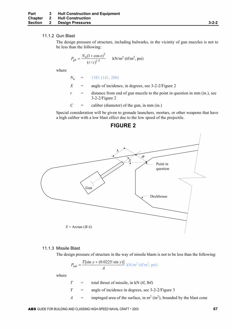
Part 3 Hull Construction and Equipment Chapter 2 Hull Construction Section 2 Design Pressures 3-2-2
ABS GUIDE FOR BUILDING AND CLASSING HIGH-SPEED NAVAL CRAFT . 2003 67
11.1.2 Gun Blast The design pressure of structure, including bulwarks, in the vicinity of gun muzzles is not to be less than the following:
5.1
24
)/()cos1(
crxNPgb
+= kN/m2 (tf/m2, psi)
where
N4 = 1381 (141, 200)
X = angle of incidence, in degrees, see 3-2-2/Figure 2
r = distance from end of gun muzzle to the point in question in mm (in.), see 3-2-2/Figure 2
C = caliber (diameter) of the gun, in mm (in.)
Special consideration will be given to grenade launchers, mortars, or other weapons that have a high caliber with a low blast effect due to the low speed of the projectile.
FIGURE 2
AB
X
Gun
Deckhouse
Point inquestion
X = Arctan (B/A)
11.1.3 Missile Blast The design pressure of structure in the way of missile blasts is not to be less than the following:
AyyTPmb)]sin0225.0([sin +
= kN/m2 (tf/m2, psi)
where
T = total thrust of missile, in kN (tf, lbf)
Y = angle of incidence in degrees, see 3-2-2/Figure 3
A = impinged area of the surface, in m2 (in2), bounded by the blast cone

Part 3 Hull Construction and Equipment Chapter 2 Hull Construction Section 2 Design Pressures 3-2-2
68 ABS GUIDE FOR BUILDING AND CLASSING HIGH-SPEED NAVAL CRAFT . 2003
FIGURE 3
Y
11.3 Human Loads Composite deck structures are to withstand a point load equivalent to the weight of a man (90.7 kg, 200 lbf) in the middle of the plate or the midspan stiffener.
11.5 Helicopter Decks
11.5.1 General Helicopter decks, where provided, are to meet the following structural and safety requirements. The attention of owners, builders and designers is directed to various Naval Administration regulations and guides regarding the operational and other design requirements for helicopters on craft. See also 4-6-4/3.9.2 and 4-6-7/9.
Plans showing the arrangement, scantlings and details of the helicopter deck are to be submitted. The arrangement plan is to show the overall size of the helicopter deck and the designated landing area. If the arrangement provides for the securing of a helicopter or helicopters to the deck, the predetermined position(s) selected to accommodate the secured helicopter, in addition to the locations of deck fittings, for securing the helicopter are to be shown. The type of helicopter to be considered is to be specified and calculations for appropriate loading conditions are to be submitted.
11.5.2 Overall Distributed Loading For a platform type helicopter decks, a minimum distributed loading of 2010 N/m2 (205 kgf/m2, 42 lbf/ft2) is to be taken over the entire helicopter deck. For all other helicopter decks, the minimum overall distributed load is to be as specified in 3-2-2/Table 4.
11.5.3 Helicopter Landing and Impact Loading A load of not less than 75% of the helicopter maximum take-off weight is to be taken on each of two square areas, 0.3 m × 0.3 m (1 ft × 1 ft). Alternatively, the manufacturer’s recommended wheel impact loading will be considered. The deck is to be considered for helicopter landings at any location within the designated landing area. The structural weight of the helicopter deck is to be added to the helicopter impact loading when considering girders, stanchions, truss supports, etc. Where the upper deck of a superstructure or deckhouse is used as a helicopter deck and the spaces below are normally manned (quarters, bridge, control room, etc) the impact loading is to be multiplied by a factor of 1.15.
11.5.4 Stowed Helicopter Loading If provisions are made to accommodate helicopter secured to the deck in a predetermined position, the structure is to be considered for a local loading not to be taken less than:
PHC = Wto (1+ 0.5nxx) + Ce kN/m2 (tf/m2, psi)
where

Part 3 Hull Construction and Equipment Chapter 2 Hull Construction Section 2 Design Pressures 3-2-2
ABS GUIDE FOR BUILDING AND CLASSING HIGH-SPEED NAVAL CRAFT . 2003 69
Wto = maximum take-off weight
nxx = same as 3-2-2/11.1.1
Ce = 0.49 (0.05, 0.07)
11.5.5 Special Landing Gear Helicopters fitted with landing gear other than wheels will be specially considered
11.7 Masts Masts are to be designed to a combined load that includes the effects of wind, gravity, and ship motion. In general, the wind load is not to be taken less than 1.45 kN/m2 (0.145 tf/m2, 0.21 psi). The ship motion dynamic loads are to include roll, pitch, heave, and slam induced loads. It is also to be demonstrated that the natural frequency of the mast will not be reached during all intended operating conditions of the craft. Masts constructed in position 1 (see 3-2-9/3) are to also consider the effects of green sea impact loads.
TABLE 4 Deck Design Pressures, pd
Location kN/m2 tf/m2 psi Exposed freeboard deck, and superstructure and deckhouse decks forward of 0.25L. 0.20L + 7.6 0.020L + 0.77 0.0088L + 1.10
Freeboard deck inside enclosed superstructures and deckhouses, exposed superstructure and deckhouse decks aft of 0.25L , and internal decks included in the hull girder bending moment
0.10L + 6.1 0.010L + 0.62 0.0044L + 0.88
Enclosed accommodations decks 5.0 0.5 0.71
Concentrated deck cargo loads W (1 + 0.5nxx) W (1 + 0.5nxx) W (1 + 0.5nxx)
Enclosed store rooms, machinery spaces, etc. ρh (1 + 0.5nxx) ρh (1 + 0.5nxx) (ρ/144)h (1 + 0.5nxx)
Notes: W = deck cargo load in kN/m2 (tf/m2 psi).
nxx = average vertical acceleration at the location under consideration as defined in 3-2-2/1.1.
ρ = cargo density in kN/m3, tf/m3, lb/ft3, not to be taken less than 7.04 (0.715, 44.8)
h = height of enclosed store room, machinery space, etc., in m (ft)
L = craft length as defined in 3-1-1/3.
FIGURE 4 Decks, Superstructures, and Deckhouse Pressures
House Tops Forward
House Front 2nd Tier & Above
House Front 1st Tier
Exposed Freeboard Deck
House Tops ForwardFreeboard Deck
House Tops Aft
Exposed DS/SS Deckhouse
ExposedFreeboardDeck

Part 3 Hull Construction and Equipment Chapter 2 Hull Construction Section 2 Design Pressures 3-2-2
70 ABS GUIDE FOR BUILDING AND CLASSING HIGH-SPEED NAVAL CRAFT . 2003
TABLE 5 Superstructures and Deckhouses Design Pressures
SI Units: Location L ≤ 12.2m
(kN/m2) 12.2m < L ≤
30.5m (kN/m2) 30.5m < L ≤ 61m (kN/m2)
61m < L ≤ 90m (kN/m2) L > 90m (kN/m2)
Superstructure and Deckhouse Front, forward of 0.4L - 1st Tier 37.9 2.45L + 7.97 82.8 0.55L + 49.5 98.7
Superstructure and Deckhouse Front, aft of 0.4L - 1st Tier 24.1 0.75L + 15 37.9 2.1L – 90 98.7
Superstructure and Deckhouse Front - 2nd Tier and above 9.8(2 + L/200) 9.8(2 + L/200) 0.46L + 7.2 0.46L + 7.2 0.46L + 7.2
Superstructure and Deckhouse Aft Ends and House Sides 1st Tier
10.3 0.19L + 8 13.8 0.27L –2.6 0.27L – 2.6
Superstructure and Deckhouse Aft Ends and House Sides 2nd Tier and Above
10.3 10.3 10.3 0.22L – 3.1 9.8(1.25 + L/200)
House Tops forward of L/2 6.9 0.09L + 5.75 8.6 8.6 8.6 House Tops aft of L/2 3.4 0.19L + 1.1 6.9 6.9 6.9
MKS Units: Location L ≤ 12.2m
(tf/m2) 12.2m < L ≤ 30.5m (tf/m2)
30.5m < L ≤ 61m (tf/m2)
61m < L ≤ 90m (tf/m2) L > 90m (tf/m2)
Superstructure and Deckhouse Front, forward of 0.4L - 1st Tier 3.87 0.25L + 0.81 8.44 0.05L + 5.05 10
Superstructure and Deckhouse Front, aft of 0.4L - 1st Tier 2.46 0.076L + 1.5 3.87 0.21L - 9.2 10
Superstructure and Deckhouse Front - 2nd Tier and above 2 + (L/200) 2 + (L/200) 0.047L + 0.73 0.047L + 0.73 0.047L + 0.73
Superstructure and Deckhouse Aft Ends and House Sides 1st Tier
1.05 0.02L + 0.82 1.41 0.027L - 0.26 0.027L - 0.26
Superstructure and Deckhouse Aft Ends and House Sides 2nd Tier and Above
1.05 1.05 1.05 0.022L - 0.32 1.25 + L/200
House Tops forward of L/2 0.7 0.009L + 0.59 0.88 0.88 0.88 House Tops aft of L/2 0.35 0.02L + 0.11 0.7 0.7 0.7
US Units: Location L ≤ 40 ft (psi) 40 ft < L ≤ 100 ft
(psi) 100 ft < L ≤ 200 ft (psi)
200 ft < L ≤ 295 ft (psi) L > 295 ft (psi)
Superstructure and Deckhouse Front, forward of 0.4L - 1st Tier 5.5 0.11L + 1.17 12 0.026L + 6.74 14.5
Superstructure and Deckhouse Front, aft of 0.4L - 1st Tier 3.5 0.033L + 2.17 5.5 0.095L -
13.42 14.5
Superstructure and Deckhouse Front - 2nd Tier and above 0.44(6.6 + L/200) 0.44(6.6 + L/200) 0.02L + 1.05 0.02L + 1.05 0.02L + 1.05
Superstructure and Deckhouse Aft Ends and House Sides 1st Tier
1.5 0.008L + 1.17 2 0.012L - 0.43 0.012L - 0.43
Superstructure and Deckhouse Aft Ends and House Sides 2nd Tier and Above
1.5 1.5 1.5 0.01L - 0.5 0.44(4.1 + L/200)
House Tops forward of L/2 1.0 0.004L + 0.83 1.25 1.25 1.25 House Tops aft of L/2 0.5 0.008L + 0.17 1.0 1.0 1.0
L = craft length as defined in 3-1-1/3.

Part 3 Hull Construction and Equipment Chapter 2 Hull Construction Section 2 Design Pressures 3-2-2
ABS GUIDE FOR BUILDING AND CLASSING HIGH-SPEED NAVAL CRAFT . 2003 71
FIGURE 5 Decks, Superstructures, and Deckhouse Pressures
House Top
Exposed SS/DH Deck
Exposed Freeboard DeckEnclosed Accom. Deck
Enclosed Accom. Deck
Freeboard Deck Inside DH/SS
House Side 1st
Tier & Above
House Side 1st Tier
FIGURE 6 Design Area Factor FD

Part 3 Hull Construction and Equipment Chapter 2 Hull Construction Section 2 Design Pressures 3-2-2
72 ABS GUIDE FOR BUILDING AND CLASSING HIGH-SPEED NAVAL CRAFT . 2003
FIGURE 7 Vertical Acceleration Distribution Factor KV
2.0
1.0
0.8
0.1 0.2 0.3 0.4 0.5 0.6 0.7 0.8 0.9 1.0
KV
Distance Along Lw from Afterward End of Lw
FIGURE 8 Vertical Acceleration Distribution Factor FV
0.2
0.9 0.8 0.7 0.6 0.5 0.4 0.3 0.2 0.1 0.0
FV
Distance Along Lw from Forward End of Lw
1.0
0.5
0.6
0.8
1.0
0.110.445
Forward
Extend to Forward Extent of HorizontalChine or Running Strake in Bottom Shell
0.4
0.25

Part 3 Hull Construction and Equipment Chapter 2 Hull Construction Section 2 Design Pressures 3-2-2
ABS GUIDE FOR BUILDING AND CLASSING HIGH-SPEED NAVAL CRAFT . 2003 73
FIGURE 9 Wet Deck Pressure Distribution Factor FI
0.2
0.1 0.2 0.3 0.4 0.5 0.6 0.7 0.8 0.9 1.0
FI
Distance Along Lw from Afterward End of Lw
0
0.5
0.6
0.8
1.0
0.4
0.1
0.3
0
0.7
0.9

This Page Intentionally Left Blank

ABS GUIDE FOR BUILDING AND CLASSING HIGH-SPEED NAVAL CRAFT . 2003 75
P A R T
3 C H A P T E R 2 Hull Structures and Arrangements
S E C T I O N 3 Plating
1 Aluminum or Steel
1.1 General The bottom shell is to extend from the keel to the chine or upper turn of bilge. In general the side shell is to be of the same thickness from its lower limit to the gunwale.
All plating is to meet the requirements for thickness as given in 3-2-3/1.3.
In addition those areas of plating associated with primary hull strength are to meet the buckling criteria as given in 3-2-3/1.5. Where plate panels are subjected to other bending, biaxial, or a combination of stresses, they will be specially considered.
The thickness of the shell plating in way of skegs, shaft struts, hawse pipes, etc. is to be increased by 50% over that obtained from 3-2-3/1.3.
The thickness of water jet tunnels and transverse thruster tubes is to be in accordance with 3-2-3/1.7.
Where the plating forms decks for the access, operation or stowage of vehicles, the plating is in addition to meet the requirements of 3-2-3/1.9.
1.3 Thickness The thickness of the shell, deck or bulkhead plating is to be not less than obtained by the following equations, whichever is greater:
1.3.1 Lateral Loading
a
pkstσ1000
= mm a
pkstσ
= in.
where
s = the spacing, in mm (in.), of the shell, deck, superstructure, deckhouse or bulkhead longitudinals or stiffeners.
p = design pressure, in kN/m2 (tf/m2, psi), given in Section 3-2-2
k = plate panel aspect ratio factor, given in 3-2-3/Table 1
σa = design stress, in N/mm2 (kgf/mm2, psi), given in 3-2-3/Table 2
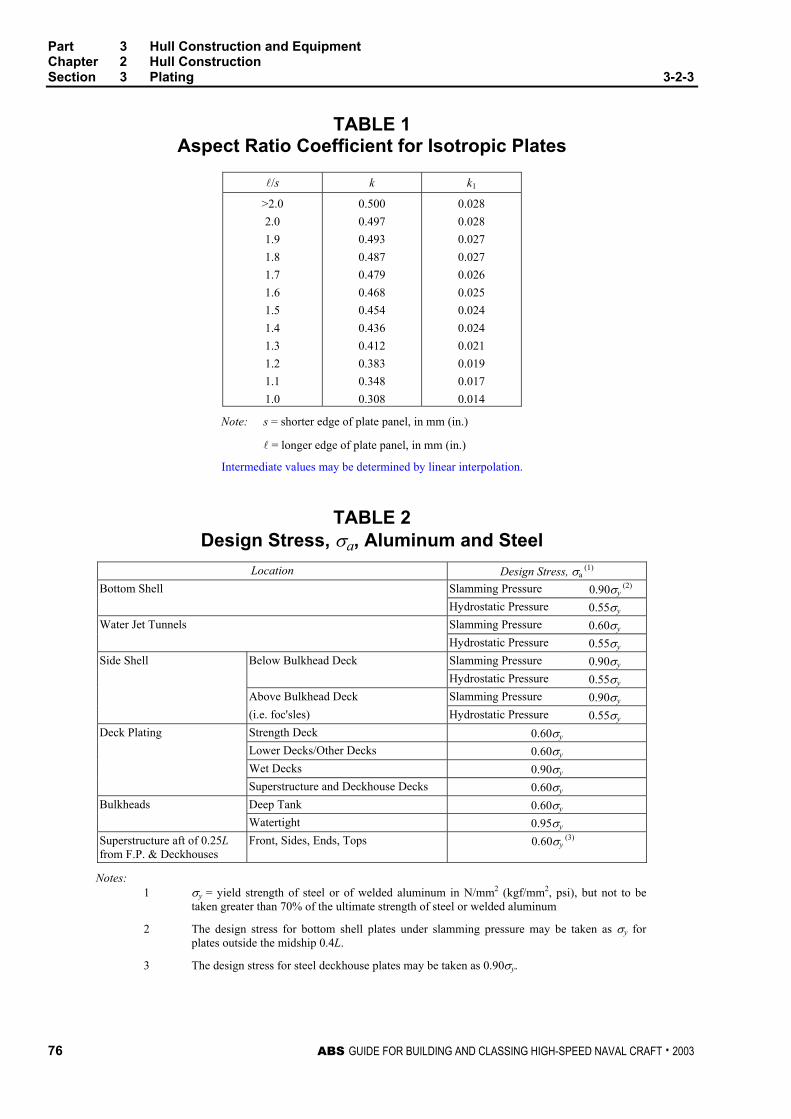
Part 3 Hull Construction and Equipment Chapter 2 Hull Construction Section 3 Plating 3-2-3
76 ABS GUIDE FOR BUILDING AND CLASSING HIGH-SPEED NAVAL CRAFT . 2003
TABLE 1 Aspect Ratio Coefficient for Isotropic Plates
l/s k k1
>2.0 2.0 1.9 1.8 1.7 1.6 1.5 1.4 1.3 1.2 1.1 1.0
0.500 0.497 0.493 0.487 0.479 0.468 0.454 0.436 0.412 0.383 0.348 0.308
0.028 0.028 0.027 0.027 0.026 0.025 0.024 0.024 0.021 0.019 0.017 0.014
Note: s = shorter edge of plate panel, in mm (in.)
l = longer edge of plate panel, in mm (in.)
Intermediate values may be determined by linear interpolation.
TABLE 2 Design Stress, σa, Aluminum and Steel
Location Design Stress, σa (1)
Bottom Shell Slamming Pressure 0.90σy (2)
Hydrostatic Pressure 0.55σy
Water Jet Tunnels Slamming Pressure 0.60σy
Hydrostatic Pressure 0.55σy
Side Shell Below Bulkhead Deck Slamming Pressure 0.90σy
Hydrostatic Pressure 0.55σy
Above Bulkhead Deck Slamming Pressure 0.90σy
(i.e. foc'sles) Hydrostatic Pressure 0.55σy
Deck Plating Strength Deck 0.60σy Lower Decks/Other Decks 0.60σy Wet Decks 0.90σy Superstructure and Deckhouse Decks 0.60σy Bulkheads Deep Tank 0.60σy Watertight 0.95σy Superstructure aft of 0.25L from F.P. & Deckhouses
Front, Sides, Ends, Tops 0.60σy (3)
Notes: 1 σy = yield strength of steel or of welded aluminum in N/mm2 (kgf/mm2, psi), but not to be
taken greater than 70% of the ultimate strength of steel or welded aluminum
2 The design stress for bottom shell plates under slamming pressure may be taken as σy for plates outside the midship 0.4L.
3 The design stress for steel deckhouse plates may be taken as 0.90σy.

Part 3 Hull Construction and Equipment Chapter 2 Hull Construction Section 3 Plating 3-2-3
ABS GUIDE FOR BUILDING AND CLASSING HIGH-SPEED NAVAL CRAFT . 2003 77
1.3.2 Thickness Based on Secondary Stiffening ts = 0.01s mm (in.) tal = 0.012s mm (in.)
where
ts = required thickness for steel craft
tal = required thickness for aluminum craft
s is as defined in 3-2-3/1.3.1.
1.3.3 Minimum Thickness The thickness of shell plating, decks and bulkheads is to be not less than obtained from the following equations:
1.3.3(a) Bottom Shell
ts = 0.44 sLq + 2.0 mm ts = 0.009 sLq + 0.08 in.
tal = 0.70 aLq + 1.0 mm tal = 0.015 aLq + 0.04 in.
where
L = craft length, as defined in 3-1-1/3
qs = 1.0 for ordinary strength steel; 245/σys, (25/σys, 34000/σys) for higher strength steels, but not to be taken less than 0.72
σys = yield strength for higher strength steel, in N/mm2 (kgf/mm2, psi)
qa = 115/σya, (12/σya, 17000/σya) for aluminum alloys.
σya = minimum unwelded yield strength for aluminum alloys, in N/mm2 (kgf/mm2, psi), but not to be taken as more than 0.7 of the ultimate tensile strength in the as-welded condition
ts and tal as defined in 3-2-3/1.3.2. However, ts is not to be taken less than 3.5 mm (0.14 in.) and tal is not to be taken less than 4.0 mm (0.16 in.)
1.3.3(b) Side Shell
ts = 0.40 sLq + 2.0 mm ts = 0.009 sLq + 0.08 in.
tal = 0.62 aLq + 1.0 mm tal = 0.013 aLq + 0.04 in.
where ts and tal are as defined in 3-2-3/1.3.2. However, ts is not to be taken less than 3.0 mm (0.12 in.) and tal is not to be taken less than 3.5 mm (0.14 in.)
qs, qa and L are as defined in 3-2-3/1.3.3(a).
1.3.3(c) Strength Deck
ts = 0.40 sLq + 1.0 mm ts = 0.009 sLq + 0.04 in.
tal = 0.62 aLq + 1.0 mm tal = 0.013 aLq + 0.04 in.
where ts and tal are as defined in 3-2-3/1.3.2. However, ts is not to be taken less than 3.0 mm (0.12 in.) and tal is not to be taken less than 3.5 mm (0.14 in.) qs, qa, and L are as defined in 3-2-3/1.3.3(a)
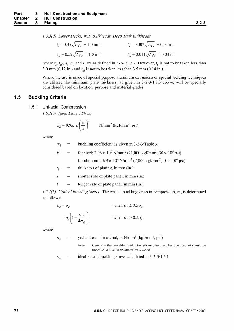
Part 3 Hull Construction and Equipment Chapter 2 Hull Construction Section 3 Plating 3-2-3
78 ABS GUIDE FOR BUILDING AND CLASSING HIGH-SPEED NAVAL CRAFT . 2003
1.3.3(d) Lower Decks, W.T. Bulkheads, Deep Tank Bulkheads
ts = 0.35 sLq + 1.0 mm ts = 0.007 sLq + 0.04 in.
tal = 0.52 aLq + 1.0 mm tal = 0.011 aLq + 0.04 in.
where ts, tal, qs, qa and L are as defined in 3-2-3/1.3.2. However, ts is not to be taken less than 3.0 mm (0.12 in.) and tal is not to be taken less than 3.5 mm (0.14 in.).
Where the use is made of special purpose aluminum extrusions or special welding techniques are utilized the minimum plate thickness, as given in 3-2-3/1.3.3 above, will be specially considered based on location, purpose and material grades.
1.5 Buckling Criteria
1.5.1 Uni-axial Compression 1.5.1(a) Ideal Elastic Stress
σE = 0.9m1E2
stb N/mm2 (kgf/mm2, psi)
where
m1 = buckling coefficient as given in 3-2-3/Table 3.
E = for steel; 2.06 × 10⁵ N/mm2 (21,000 kgf/mm2, 30 × 106 psi)
for aluminum 6.9 × 10⁴ N/mm2 (7,000 kgf/mm2, 10 × 106 psi)
tb = thickness of plating, in mm (in.)
s = shorter side of plate panel, in mm (in.)
l = longer side of plate panel, in mm (in.)
1.5.1(b) Critical Buckling Stress. The critical buckling stress in compression, σc, is determined as follows:
σc = σE when σE ≤ 0.5σy
= σy
−
E
y
σσ4
1 when σE > 0.5σy
where
σy = yield stress of material, in N/mm2 (kgf/mm2, psi)
Note: Generally the unwelded yield strength may be used, but due account should be made for critical or extensive weld zones.
σE = ideal elastic buckling stress calculated in 3-2-3/1.5.1
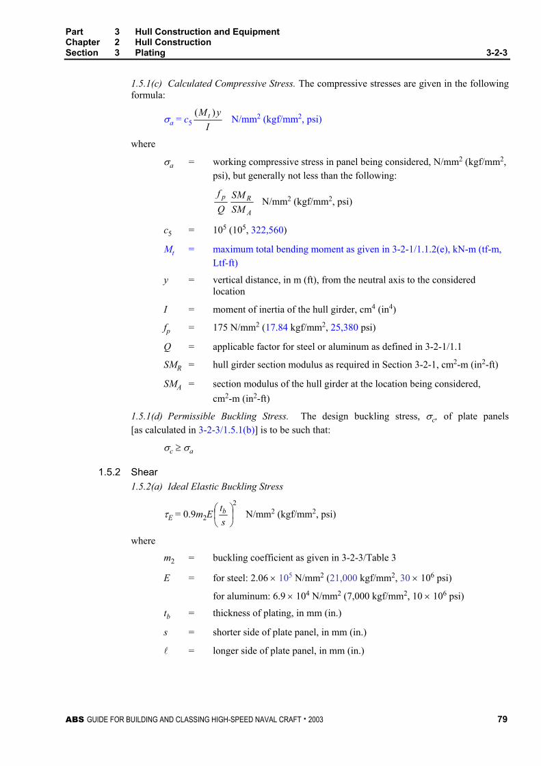
Part 3 Hull Construction and Equipment Chapter 2 Hull Construction Section 3 Plating 3-2-3
ABS GUIDE FOR BUILDING AND CLASSING HIGH-SPEED NAVAL CRAFT . 2003 79
1.5.1(c) Calculated Compressive Stress. The compressive stresses are given in the following formula:
σa = c5 IyM t )(
N/mm2 (kgf/mm2, psi)
where
σa = working compressive stress in panel being considered, N/mm2 (kgf/mm2, psi), but generally not less than the following:
A
Rp
SMSM
Qf
N/mm2 (kgf/mm2, psi)
c5 = 105 (105, 322,560)
Mt = maximum total bending moment as given in 3-2-1/1.1.2(e), kN-m (tf-m, Ltf-ft)
y = vertical distance, in m (ft), from the neutral axis to the considered location
I = moment of inertia of the hull girder, cm4 (in4)
fp = 175 N/mm2 (17.84 kgf/mm2, 25,380 psi)
Q = applicable factor for steel or aluminum as defined in 3-2-1/1.1
SMR = hull girder section modulus as required in Section 3-2-1, cm2-m (in2-ft)
SMA = section modulus of the hull girder at the location being considered, cm2-m (in2-ft)
1.5.1(d) Permissible Buckling Stress. The design buckling stress, σc, of plate panels [as calculated in 3-2-3/1.5.1(b)] is to be such that:
σc ≥ σa
1.5.2 Shear 1.5.2(a) Ideal Elastic Buckling Stress
τE = 0.9m2E2
stb N/mm2 (kgf/mm2, psi)
where
m2 = buckling coefficient as given in 3-2-3/Table 3
E = for steel: 2.06 × 10⁵ N/mm2 (21,000 kgf/mm2, 30 × 106 psi)
for aluminum: 6.9 × 10⁴ N/mm2 (7,000 kgf/mm2, 10 × 106 psi)
tb = thickness of plating, in mm (in.)
s = shorter side of plate panel, in mm (in.)
l = longer side of plate panel, in mm (in.)
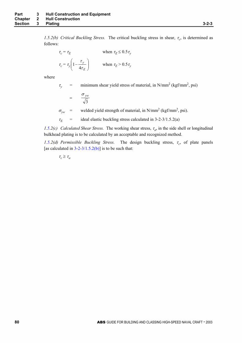
Part 3 Hull Construction and Equipment Chapter 2 Hull Construction Section 3 Plating 3-2-3
80 ABS GUIDE FOR BUILDING AND CLASSING HIGH-SPEED NAVAL CRAFT . 2003
1.5.2(b) Critical Buckling Stress. The critical buckling stress in shear, τc, is determined as follows:
τc = τE when τE ≤ 0.5τy
τc = τy
−
E
y
ττ4
1 when τE > 0.5τy
where
τy = minimum shear yield stress of material, in N/mm2 (kgf/mm2, psi)
= 3ywσ
σyw = welded yield strength of material, in N/mm2 (kgf/mm2, psi).
τE = ideal elastic buckling stress calculated in 3-2-3/1.5.2(a)
1.5.2(c) Calculated Shear Stress. The working shear stress, τa, in the side shell or longitudinal bulkhead plating is to be calculated by an acceptable and recognized method.
1.5.2(d) Permissible Buckling Stress. The design buckling stress, τc, of plate panels [as calculated in 3-2-3/1.5.2(b)] is to be such that:
τc ≥ τa
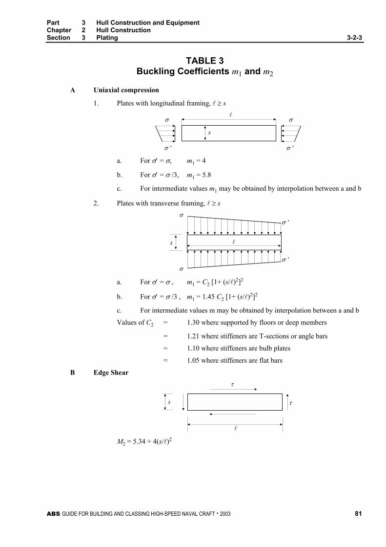
Part 3 Hull Construction and Equipment Chapter 2 Hull Construction Section 3 Plating 3-2-3
ABS GUIDE FOR BUILDING AND CLASSING HIGH-SPEED NAVAL CRAFT . 2003 81
TABLE 3 Buckling Coefficients m1 and m2
A Uniaxial compression
1. Plates with longitudinal framing, l ≥ s
σ
σ '
σ
σ '
l
s
a. For σ′ = σ, m1 = 4
b. For σ′ = σ /3, m1 = 5.8
c. For intermediate values m1 may be obtained by interpolation between a and b
2. Plates with transverse framing, l ≥ s σ
σ 'σ
σ '
s l
a. For σ′ = σ , m1 = C2 [1+ (s/l)2]2
b. For σ′ = σ /3 , m1 = 1.45 C2 [1+ (s/l)2]2
c. For intermediate values m may be obtained by interpolation between a and b
Values of C2 = 1.30 where supported by floors or deep members
= 1.21 where stiffeners are T-sections or angle bars
= 1.10 where stiffeners are bulb plates
= 1.05 where stiffeners are flat bars
B Edge Shear τ
τs
l M2 = 5.34 + 4(s/l)2

Part 3 Hull Construction and Equipment Chapter 2 Hull Construction Section 3 Plating 3-2-3
82 ABS GUIDE FOR BUILDING AND CLASSING HIGH-SPEED NAVAL CRAFT . 2003
1.7 Water Jet Tunnels and Transverse Thruster Tubes
1.7.1 Water Jet Tunnels The thickness for the water jet tunnel plating is to be not less than required by 3-2-3/1.3, neither is it to be less than the greater of the jet manufacturer’s recommended thickness or that obtained from the following equation:
a
t kpst
σ1000= mm
a
t kpst
σ= in.
where
pt = maximum positive or negative tunnel design pressure, in kN/m2 (tf/m2, psi), as provided by the jet manufacturer.
s, k and σa are as given in 3-2-3/1.3.
1.7.2 Transverse Thruster Tunnels The thickness of the tunnel plating for the transverse thrusters is to be not less than required by 3-2-3/1.3, nor less than obtained from the following equation:
t = 0.008d Q + 3.0 mm t = 0.008d Q + 0.12 in.
where
d = inside diameter of the tunnel in mm (in.), but is taken as not less than 968 mm (38 in.)
Q is as given in 3-2-1/1.1.
1.9 Decks Provided for the Operation or Stowage of Vehicles Where provision is to be made for the operation or stowage of vehicles having rubber tires, and after all other requirements are met, the thickness of deck plating is to be not less than obtained from the following equation:
a
xxnWtσ
β )5.01( += mm (in.)
where
W = static wheel load, in N (lbf)
nxx = average vertical acceleration at the location under consideration as defined in 3-2-2/1.1
β = as given in 3-2-3/Figure 1
σa = design stress for decks, in N/mm2 (kgf/mm2, psi), given in 3-2-3/Table 2
For wheel loading, strength deck plating thickness is to be not less than 110% of that required by the above equation, and platform deck plating thickness is to be not less than 90% of that required by the above equation.
Where the wheels are close together, special consideration will be given to the use of combined imprint and load. Where the intended operation is such that only the larger dimension of the wheel imprint is perpendicular to the longer edge of the plate panel, then b below may be taken as the smaller wheel imprint dimension, in which case, a is to be the greater one.

Part 3 Hull Construction and Equipment Chapter 2 Hull Construction Section 3 Plating 3-2-3
ABS GUIDE FOR BUILDING AND CLASSING HIGH-SPEED NAVAL CRAFT . 2003 83
FIGURE 1 Values for β
b
a
s
l
b/s l/s = 1 l/s = 1.4 l/s ≥ 2
a/s 0 0.2 0.4 0.6 0.8 1 0 0.2 0.4 0.8 1.2 1.4 0 0.4 0.8 1.2 1.6 2 0 1.82 1.38 1.12 0.93 0.76 2.00 1.55 1.12 0.84 0.75 1.64 1.20 0.97 0.78 0.64
0.2 1.82 1.28 1.08 0.90 0.76 0.63 1.78 1.43 1.23 0.95 0.74 0.64 1.73 1.31 1.03 0.84 0.68 0.570.4 1.39 1.07 0.84 0.72 0.62 0.52 1.39 1.13 1.00 0.80 0.62 0.55 1.32 1.08 0.88 0.74 0.60 0.500.6 1.12 0.90 0.74 0.60 0.52 0.43 1.10 0.91 0.82 0.68 0.53 0.47 1.04 0.90 0.76 0.64 0.54 0.440.8 0.92 0.76 0.62 0.51 0.42 0.36 0.90 0.76 0.68 0.57 0.45 0.40 0.87 0.76 0.63 0.54 0.44 0.381 0.76 0.63 0.52 0.42 0.35 0.30 0.75 0.62 0.57 0.47 0.38 0.33 0.71 0.61 0.53 0.45 0.38 0.30
Notes: s = spacing of deck beams or deck longitudinals, in mm (in.)
l = length of plate pane, in mm (in.)
a = wheel imprint dimension, in mm (in.), paralleled to the shorter edge, s, of the plate panel, and in general the lesser wheel imprint dimension
b = wheel imprint dimension, in mm (in.), parallel to the longer edge, l, of the plate panel, and in general the longer wheel imprint dimension
3 Aluminum Extruded Planking, Aluminum Sandwich Panels and Corrugated Panels
3.1 Aluminum Extruded Planking Extruded planking is to be reviewed similar to a conventional stiffener and plate combination. The required thickness of the planking between stiffeners is given in 3-2-3/1.3 and 3-2-3/1.5. For box and truss type extrusion, the plate spacing is to be taken as the maximum unsupported span of plate as indicated in 3-2-3/Figure 2. The stiffeners on the planking are to comply with the requirements in 3-2-4/1.3, 3-2-4/1.5 and 3-2-4/1.7. The geometry of stiffeners in box and truss type extrusions is as indicated in 3-2-3/Figure 2. The individual planking pieces are to be attached by continuous welding for the main deck and can be welded intermittently for interior accommodation decks. The intermittent weld for the interior decks is to be sized in accordance with 3-2-13/1 for beams and stiffeners to deck. The use of adhesives for attaching planking members used for weather coverings is to be specially considered/

Part 3 Hull Construction and Equipment Chapter 2 Hull Construction Section 3 Plating 3-2-3
84 ABS GUIDE FOR BUILDING AND CLASSING HIGH-SPEED NAVAL CRAFT . 2003
FIGURE 2 Extruded Planking
=
=
s
s
3.3 Aluminum Sandwich Panels An aluminum sandwich panel is a panel with thin aluminum skins attached to a thicker core material. These panels are to be typically used on enclosed decks or bulkheads. Where exposed panels are proposed the effects due to heat and the coefficients of thermal expansion are to be addressed. In general, the inner and outer skins are to be of the same thickness. The use of aluminum sandwich panels for helicopter decks and wheel loading will be specially considered. Aluminum sandwich panels are to comply with the equations given below:
3.3.1 Section Modulus of Skins The section modulus about the neutral axis of a strip of sandwich panel, 1 cm (1 in.) wide is not to be less than the following equation:
SM = a
pksσ5
2
106× cm3 SM =
a
pksσ6
2 in3
where
s = the spacing of the shell or deck longitudinals or superstructure, deckhouse or bulkhead stiffener, in mm (in.). It is always to be the lesser dimension of the unsupported plate panels
p = design pressure, given in Section 3-2-2 k = coefficient varying with plate panel aspect ratio, given in 3-2-3/Table 1 σa = design stress, given in 3-2-3/Table 2
3.3.2 Moment of Inertia of Skins The moment of inertia about the neutral axis of a strip of sandwich panel, 1 cm (1 in.) wide is not to be less than the following equation:
I = E
pks24.010120 5
13
⋅× cm4 I =
Epks
24.01
3 in4
where
s = the spacing of the shell or deck longitudinals or superstructure, deckhouse or bulkhead stiffener, in mm (in.). It is always to be the lesser dimension of the unsupported plate panels

Part 3 Hull Construction and Equipment Chapter 2 Hull Construction Section 3 Plating 3-2-3
ABS GUIDE FOR BUILDING AND CLASSING HIGH-SPEED NAVAL CRAFT . 2003 85
p = design pressure, given in Section 3-2-2
k1 = coefficient varying with plate panel aspect ratio, given in 3-2-3/Table 1
E = tensile modulus of aluminum, in N/mm2 (kgf/mm2, psi), as defined in 3-2-3/1.5.2
3.3.3 Core Shear Strength The thickness of core and sandwich is to be not less than given by the following equation:
a
co vpsddτ10002
=+
mm τ
vpsdd co =+2
in.
where
do = overall thickness of sandwich, in mm (in.)
dc = thickness of core, in mm (in.)
v = coefficient varying with plate panel aspect ratio, given in 3-2-3/Table 6
s = lesser dimension of plate panel, in mm (in.)
p = design pressure, in kN/m2 (tf/m2, psi), as defined in Section 3-2-2
τ = design stress, N/mm2 (kgf/mm2, psi), as shown in 3-2-3/Table 7.
3.3.4 Testing The core material and the attachment of the skins to the core are to be tested in accordance with the requirements in 2-6-5/11
3.3.5 Attachment Typically, beams and stiffeners are not to be considered as effectively attached. Panels are not to be welded to unless the possible damage from heat is addressed. The panels are to be bolted to surrounding structure. The use of adhesives will be specially considered.
3.5 Corrugated Panels
3.5.1 Plating The plating of corrugated panels is to be of the thickness required by 3-2-3/1.3 with the following modification. The spacing to be used is the greater of dimensions a or c as indicated in 3-2-4/Figure 3
5 Fiber Reinforced Plastic
5.1 General The shell, decks and bulkheads may be either single skin or sandwich construction. Where both are used, a suitable transition is to be obtained between them with a minimum 12:1 taper ratio.
The bottom shell is to extend to the chine or upper bilge turn. A suitable transition is to be obtained between the bottom and side shell plating. The shell thickness in way of the keel is to be 50% greater and in way of shaft struts and skegs is to be 100% greater than the thickness required by 3-2-3/5.5.1 or 3-2-3/5.5.2, as applicable. For this purpose, pressure pb as obtained from 3-2-2/1.1 or 3-2-2/3.1 and actual frame spacing at the location of the member are to be used for 3-2-3/5.5.1. Suitable framing reinforcement is to be provided in way of shaft struts. Bow thruster tube thickness is to be equivalent to the surrounding shell thickness.
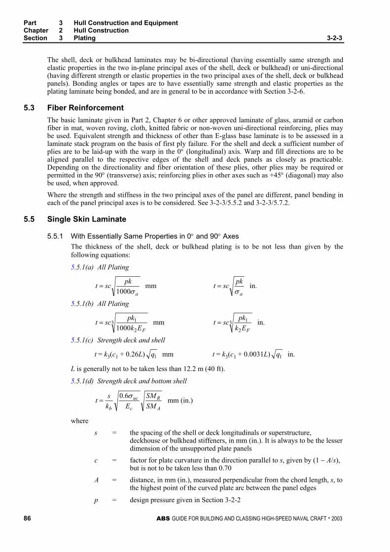
Part 3 Hull Construction and Equipment Chapter 2 Hull Construction Section 3 Plating 3-2-3
86 ABS GUIDE FOR BUILDING AND CLASSING HIGH-SPEED NAVAL CRAFT . 2003
The shell, deck or bulkhead laminates may be bi-directional (having essentially same strength and elastic properties in the two in-plane principal axes of the shell, deck or bulkhead) or uni-directional (having different strength or elastic properties in the two principal axes of the shell, deck or bulkhead panels). Bonding angles or tapes are to have essentially same strength and elastic properties as the plating laminate being bonded, and are in general to be in accordance with Section 3-2-6.
5.3 Fiber Reinforcement The basic laminate given in Part 2, Chapter 6 or other approved laminate of glass, aramid or carbon fiber in mat, woven roving, cloth, knitted fabric or non-woven uni-directional reinforcing, plies may be used. Equivalent strength and thickness of other than E-glass base laminate is to be assessed in a laminate stack program on the basis of first ply failure. For the shell and deck a sufficient number of plies are to be laid-up with the warp in the 0° (longitudinal) axis. Warp and fill directions are to be aligned parallel to the respective edges of the shell and deck panels as closely as practicable. Depending on the directionality and fiber orientation of these plies, other plies may be required or permitted in the 90° (transverse) axis; reinforcing plies in other axes such as +45° (diagonal) may also be used, when approved. Where the strength and stiffness in the two principal axes of the panel are different, panel bending in each of the panel principal axes is to be considered. See 3-2-3/5.5.2 and 3-2-3/5.7.2.
5.5 Single Skin Laminate
5.5.1 With Essentially Same Properties in 0° and 90° Axes The thickness of the shell, deck or bulkhead plating is to be not less than given by the following equations:
5.5.1(a) All Plating
a
pksctσ1000
= mm a
pksctσ
= in.
5.5.1(b) All Plating
32
11000 FEk
pksct = mm 32
1
FEkpksct = in.
5.5.1(c) Strength deck and shell
t = k3(c1 + 0.26L) 1q mm t = k3(c1 + 0.0031L) 1q in.
L is generally not to be taken less than 12.2 m (40 ft).
5.5.1(d) Strength deck and bottom shell
A
R
c
uc
b SMSM
Ekst σ6.0
= mm (in.)
where
s = the spacing of the shell or deck longitudinals or superstructure, deckhouse or bulkhead stiffeners, in mm (in.). It is always to be the lesser dimension of the unsupported plate panels
c = factor for plate curvature in the direction parallel to s, given by (1 − A/s), but is not to be taken less than 0.70
A = distance, in mm (in.), measured perpendicular from the chord length, s, to the highest point of the curved plate arc between the panel edges
p = design pressure given in Section 3-2-2

Part 3 Hull Construction and Equipment Chapter 2 Hull Construction Section 3 Plating 3-2-3
ABS GUIDE FOR BUILDING AND CLASSING HIGH-SPEED NAVAL CRAFT . 2003 87
k or k1 = coefficient varying with plate panel aspect ratio, given in 3-2-3/Table 1
kb = 2.5 with longitudinal framing
= 2.5 with transverse framing and panel aspect ratio of 1.0
= 1.0 with transverse framing and panel aspect ratio 2.0 to 4.0
σa = design stress given in 3-2-3/Table 4
k2 = for bottom plating; 0.015 for patrol boats and similar service craft, 0.01 for other craft.
= for side plating; 0.020 for patrol boats and similar service craft, 0.015 for other craft
= for superstructures and deckhouse fronts; 0.025
= for other plating; 0.010
EF = flexural modulus of laminate, in N/mm2 (kgf/mm2, psi), in the direction parallel to s
q1 = 170/F (15.5/F, 25,000/F)
L = craft length, in m (ft), as defined in 3-1-1/3
c1 = 5.7 mm (0.225 in.)
k3 = 1.2 for bottom shell structure
= 1.0 for side shell and deck structure
Ec = compressive modulus of elasticity in N/mm2 (kgf/mm2, psi) F = minimum flexural strength of laminate, in N/mm2 (kgf/mm2, psi) σuc = minimum compressive strength of laminate, in N/mm2 (kgf/mm2, psi) SMR = required hull-girder section modulus given in Section 3-2-1 SMA = proposed hull-girder section modulus of midship section.
TABLE 4 Design Stresses for FRP, σa
Bottom Shell 0.33σu Side Shell 0.33σu Decks 0.33σu Superstructure and Deckhouses – Front, Sides, Ends, and Tops 0.33σu Tank Bulkheads 0.33σu Watertight Bulkheads 0.50σu
For single skin laminates:
σu = minimum flexural strength, in N/mm2 (kgf/mm2, psi)
For sandwich laminates:
σu = for shell or deck outer skin, minimum tensile strength, in N/mm2 (kgf/mm2, psi)
σu = for shell or deck inner skin, minimum compressive strength, in N/mm2 (kgf/mm2, psi)
σu = for bulkheads, lesser of tensile or compressive strength, in N/mm2 (kgf/mm2, psi)
Note: σu is to be verified from the approved test results. See Section 2-6-5.
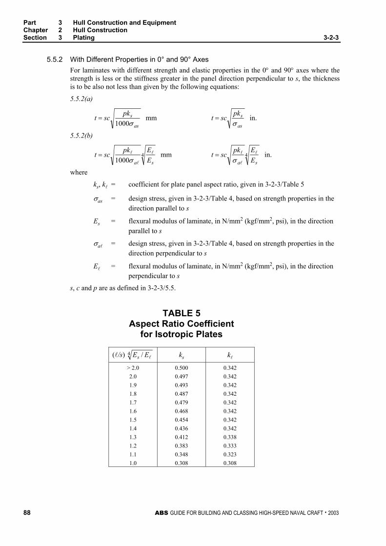
Part 3 Hull Construction and Equipment Chapter 2 Hull Construction Section 3 Plating 3-2-3
88 ABS GUIDE FOR BUILDING AND CLASSING HIGH-SPEED NAVAL CRAFT . 2003
5.5.2 With Different Properties in 0° and 90° Axes For laminates with different strength and elastic properties in the 0° and 90° axes where the strength is less or the stiffness greater in the panel direction perpendicular to s, the thickness is to be also not less than given by the following equations:
5.5.2(a)
as
spksctσ1000
= mm as
spksctσ
= in.
5.5.2(b)
41000 sa E
Epksct l
l
l
σ= mm 4
sa EEpksct l
l
l
σ= in.
where
ks, kl = coefficient for plate panel aspect ratio, given in 3-2-3/Table 5
σas = design stress, given in 3-2-3/Table 4, based on strength properties in the direction parallel to s
Es = flexural modulus of laminate, in N/mm2 (kgf/mm2, psi), in the direction parallel to s
σal = design stress, given in 3-2-3/Table 4, based on strength properties in the direction perpendicular to s
El = flexural modulus of laminate, in N/mm2 (kgf/mm2, psi), in the direction perpendicular to s
s, c and p are as defined in 3-2-3/5.5.
TABLE 5 Aspect Ratio Coefficient
for Isotropic Plates
(l/s) 4 / lEEs ks kl
> 2.0 2.0 1.9 1.8 1.7 1.6 1.5 1.4 1.3 1.2 1.1 1.0
0.500 0.497 0.493 0.487 0.479 0.468 0.454 0.436 0.412 0.383 0.348 0.308
0.342 0.342 0.342 0.342 0.342 0.342 0.342 0.342 0.338 0.333 0.323 0.308

Part 3 Hull Construction and Equipment Chapter 2 Hull Construction Section 3 Plating 3-2-3
ABS GUIDE FOR BUILDING AND CLASSING HIGH-SPEED NAVAL CRAFT . 2003 89
5.7 Sandwich Laminate
5.7.1 Laminate with Essentially Same Bending Strength and Stiffness in 0° and 90° Axes In general the outer and inner skins are to be similar in lay-up and in strength and elastic properties. Special consideration will be given where this is not the case. In general, single skin laminate is to be used in way of the keel and in way of hull appendages such as shaft struts, skegs and rudders and in way of deck fittings, bolted connections, and other areas of concentrated local loads.
The section modulus and moment of inertia about the neutral axis of a strip of sandwich panel, 1 cm (1 in.) wide are to be not less than given by the following equations:
5.7.1(a)
aoo
pkscSMσ5
2
106)(
×= cm3
aoo
pkscSMσ6)( 2
= in3
5.7.1(b)
aii
pkscSMσ5
2
106)(
×= cm3
aii
pkscSMσ6)( 2
= in3
5.7.1(c)
tcEkpkscI
25
13
10120)(
×= cm4
tcEkpkscI
2
13
12)(
= in4
where
SMo = required section modulus, in cm3 (in3), to outer skin.
SMi = required section modulus, in cm3 (in3), to inner skin.
I = required moment of inertia, in cm4 (in4)
σao = design stress, for outer skin, given in 3-2-3/Table 4, based on strength of outer skin in direction parallel to s.
σai = design stress, for inner skin, given in 3-2-3/Table 4, based on strength of inner skin in direction parallel to s.
Etc = 0.5 (Ec + Et)
Ec = mean of compressive modulii of inner and outer skins, in N/mm2 (kgf/cm2, psi)
Et = means of tensile modulii of inner and outer skins, in N/mm2 (kgf/cm2, psi)
s, c, p, k, k1 and k2 are as defined in 3-2-3/5.5.
5.7.2 Laminates with Different Bending Strength and Stiffness in 0° and 90° Axes Where the strength is less or the stiffness greater in the direction perpendicular to s, the section modulus and moment of inertia about the neutral axis of a strip of sandwich, 1 cm (1 in.) wide are also to be not less than given by the following equations:
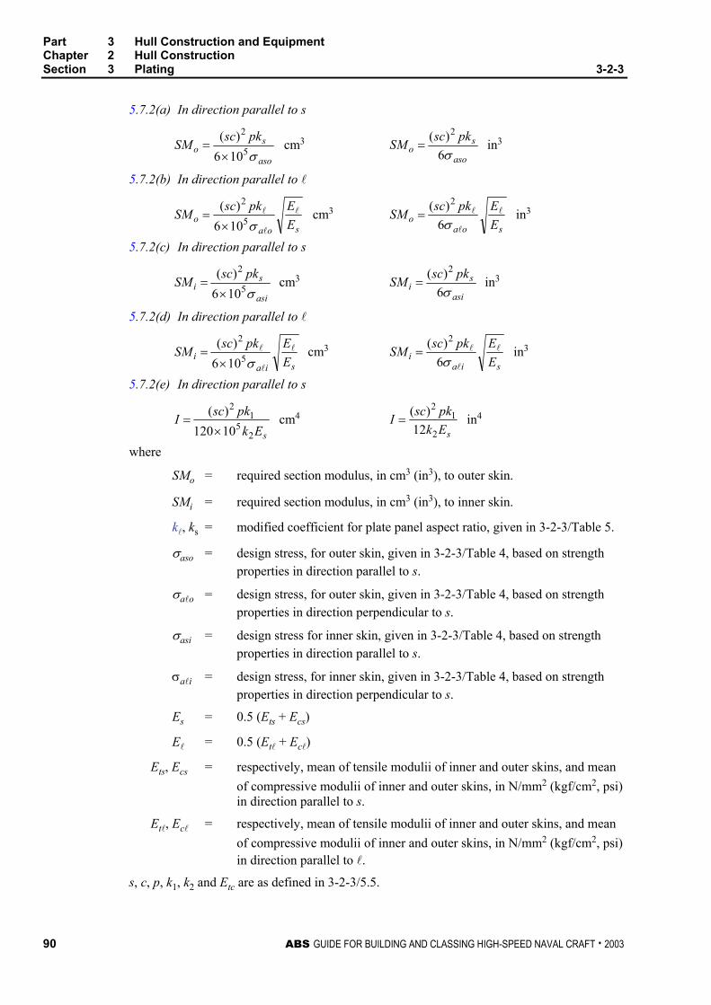
Part 3 Hull Construction and Equipment Chapter 2 Hull Construction Section 3 Plating 3-2-3
90 ABS GUIDE FOR BUILDING AND CLASSING HIGH-SPEED NAVAL CRAFT . 2003
5.7.2(a) In direction parallel to s
aso
so
pkscSMσ5
2
106)(
×= cm3
aso
so
pkscSMσ6)( 2
= in3
5.7.2(b) In direction parallel to l
soao E
EpkscSM l
l
l
σ5
2
106)(
×= cm3
soao E
EpkscSM l
l
l
σ6)( 2
= in3
5.7.2(c) In direction parallel to s
asi
si
pkscSMσ5
2
106)(
×= cm3
asi
si
pkscSMσ6)( 2
= in3
5.7.2(d) In direction parallel to l
siai E
EpkscSM l
l
l
σ5
2
106)(
×= cm3
siai E
EpkscSM l
l
l
σ6)( 2
= in3
5.7.2(e) In direction parallel to s
sEkpkscI
25
12
10120)(
×= cm4
sEkpkscI
2
12
12)(
= in4
where
SMo = required section modulus, in cm3 (in3), to outer skin.
SMi = required section modulus, in cm3 (in3), to inner skin.
kl, ks = modified coefficient for plate panel aspect ratio, given in 3-2-3/Table 5.
σaso = design stress, for outer skin, given in 3-2-3/Table 4, based on strength properties in direction parallel to s.
σalo = design stress, for outer skin, given in 3-2-3/Table 4, based on strength properties in direction perpendicular to s.
σasi = design stress for inner skin, given in 3-2-3/Table 4, based on strength properties in direction parallel to s.
σali = design stress, for inner skin, given in 3-2-3/Table 4, based on strength properties in direction perpendicular to s.
Es = 0.5 (Ets + Ecs)
El = 0.5 (Etl + Ecl)
Ets, Ecs = respectively, mean of tensile modulii of inner and outer skins, and mean of compressive modulii of inner and outer skins, in N/mm2 (kgf/cm2, psi) in direction parallel to s.
Etl, Ecl = respectively, mean of tensile modulii of inner and outer skins, and mean of compressive modulii of inner and outer skins, in N/mm2 (kgf/cm2, psi) in direction parallel to l.
s, c, p, k1, k2 and Etc are as defined in 3-2-3/5.5.
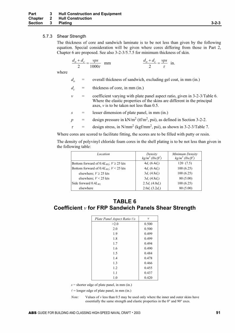
Part 3 Hull Construction and Equipment Chapter 2 Hull Construction Section 3 Plating 3-2-3
ABS GUIDE FOR BUILDING AND CLASSING HIGH-SPEED NAVAL CRAFT . 2003 91
5.7.3 Shear Strength The thickness of core and sandwich laminate is to be not less than given by the following equation. Special consideration will be given where cores differing from those in Part 2, Chapter 6 are proposed. See also 3-2-3/5.7.5 for minimum thickness of skin.
τ10002vpsdd co =
+ mm τ
vpsdd co =+2
in.
where
do = overall thickness of sandwich, excluding gel coat, in mm (in.)
dc = thickness of core, in mm (in.)
v = coefficient varying with plate panel aspect ratio, given in 3-2-3/Table 6. Where the elastic properties of the skins are different in the principal axes, v is to be taken not less than 0.5.
s = lesser dimension of plate panel, in mm (in.) p = design pressure in kN/m2 (tf/m2, psi), as defined in Section 3-2-2. τ = design stress, in N/mm2 (kgf/mm2, psi), as shown in 3-2-3/Table 7.
Where cores are scored to facilitate fitting, the scores are to be filled with putty or resin.
The density of polyvinyl chloride foam cores in the shell plating is to be not less than given in the following table:
Location Density kg/m3 (lbs/ft3)
Minimum Density kg/m3 (lbs/ft3)
Bottom forward of 0.4LWL; V ≥ 25 kts 4dc (6.4dc) 120 (7.5) Bottom forward of 0.4LWL; V < 25 kts 4dc (6.4dc) 100 (6.25) elsewhere; V ≥ 25 kts 3dc (4.8dc) 100 (6.25) elsewhere; V < 25 kts 3dc (4.8dc) 80 (5.00) Side forward 0.4LWL 2.5dc (4.0dc) 100 (6.25) elsewhere 2.0dc (3.2dc) 80 (5.00)
TABLE 6 Coefficient v for FRP Sandwich Panels Shear Strength
Plate Panel Aspect Ratio l/s v >2.0 2.0 1.9 1.8 1.7 1.6 1.5 1.4 1.3 1.2 1.1 1.0
0.500 0.500 0.499 0.499 0.494 0.490 0.484 0.478 0.466 0.455 0.437 0.420
s = shorter edge of plate panel, in mm (in.) l = longer edge of plate panel, in mm (in.)
Note: Values of v less than 0.5 may be used only where the inner and outer skins have essentially the same strength and elastic properties in the 0° and 90° axes.
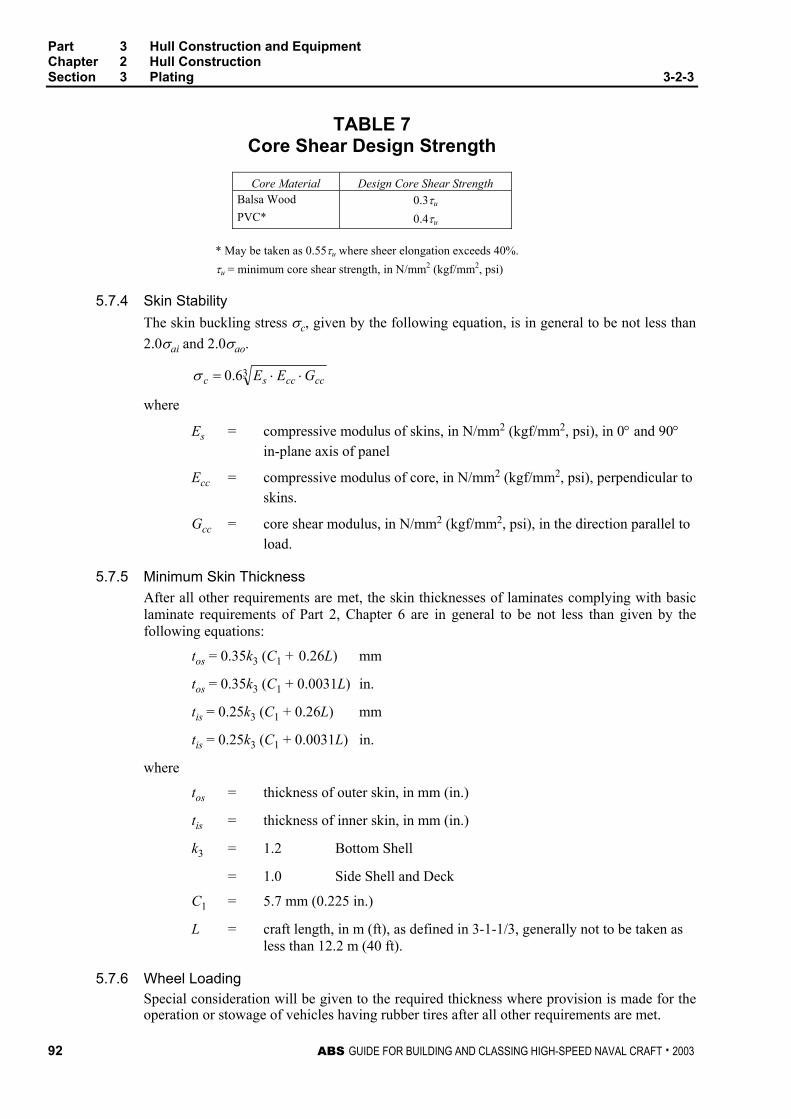
Part 3 Hull Construction and Equipment Chapter 2 Hull Construction Section 3 Plating 3-2-3
92 ABS GUIDE FOR BUILDING AND CLASSING HIGH-SPEED NAVAL CRAFT . 2003
TABLE 7 Core Shear Design Strength
Core Material Design Core Shear Strength Balsa Wood PVC*
0.3τu 0.4τu
* May be taken as 0.55τu where sheer elongation exceeds 40%. τu = minimum core shear strength, in N/mm2 (kgf/mm2, psi)
5.7.4 Skin Stability The skin buckling stress σc, given by the following equation, is in general to be not less than 2.0σai and 2.0σao.
36.0 ccccsc GEE ⋅⋅=σ
where
Es = compressive modulus of skins, in N/mm2 (kgf/mm2, psi), in 0° and 90° in-plane axis of panel
Ecc = compressive modulus of core, in N/mm2 (kgf/mm2, psi), perpendicular to skins.
Gcc = core shear modulus, in N/mm2 (kgf/mm2, psi), in the direction parallel to load.
5.7.5 Minimum Skin Thickness After all other requirements are met, the skin thicknesses of laminates complying with basic laminate requirements of Part 2, Chapter 6 are in general to be not less than given by the following equations:
tos = 0.35k3 (C1 + 0.26L) mm
tos = 0.35k3 (C1 + 0.0031L) in.
tis = 0.25k3 (C1 + 0.26L) mm
tis = 0.25k3 (C1 + 0.0031L) in.
where
tos = thickness of outer skin, in mm (in.)
tis = thickness of inner skin, in mm (in.)
k3 = 1.2 Bottom Shell
= 1.0 Side Shell and Deck
C1 = 5.7 mm (0.225 in.)
L = craft length, in m (ft), as defined in 3-1-1/3, generally not to be taken as less than 12.2 m (40 ft).
5.7.6 Wheel Loading Special consideration will be given to the required thickness where provision is made for the operation or stowage of vehicles having rubber tires after all other requirements are met.

Part 3 Hull Construction and Equipment Chapter 2 Hull Construction Section 3 Plating 3-2-3
ABS GUIDE FOR BUILDING AND CLASSING HIGH-SPEED NAVAL CRAFT . 2003 93
7 Plating Subject to Military Mission Loads
A first principles analysis is to be performed for all plates that are subject to a military mission load. The maximum stresses and deflections in these plates are not to exceed the stresses given in 3-2-3/Table 8.
TABLE 8 FRP
Steel Aluminum σ δ Weapon Foundation 0.5σy 0.5σyw 0.33σu 0.01s Gun Blast 0.80σy 0.75σyw 0.33συ 0.01s
Own craft weapon firing effects
Missile Blast σy σyw See Note 3 See Note 3 Human Load --- --- 0.33σu 0.01s
Overall Dist. Loading 0.60σy 0.6σyw See Note 3 See Note 3 Landing Impact Loading σy σyw See Note 3 See Note 3
Helicopter Decks (4)
Stowed Aircraft Loading σy σyw See Note 3 See Note 3 Masts (1) 0.4σy (2) 0.4σyw (2) See Note 3 See Note 3
σy = yield strength of steel in N/mm2 (kgf/mm2, psi)
σyw = welded yield strength of aluminum in N/mm2 (kgf/mm2, psi)
s = panel spacing
For single skin laminates:
σu = minimum flexural strength, in N/mm2 (kgf/mm2, psi)
For sandwich laminates:
σu = for shell or deck outer skin, minimum tensile strength, in N/mm2 (kgf/mm2, psi)
σu = for shell or deck inner skin, minimum compressive strength, in N/mm2 (kgf/mm2, psi)
σu = for bulkheads, lesser of tensile or compressive strength, in N/mm2 (kgf/mm2, psi)
Notes: σu is to be verified from the approved test results. See Section 2-6-5
1 The pretension of stays are to be 0.020Bs. The maximum tension in the stays is 0.40Bs or 0.35Βs for masts with two levels of stays
2 Stayed masts are to be checked in the unstayed position with an allowable stress of 0.80σy for steel or 0.80σyw for aluminum
3 Composites will be specially considered for use in this location.
The minimum plate thickness is generally not to be less than obtained from the following:
TABLE 9 Beam Spacing ts tal
460 mm (18 in.) 4.0 mm (0.16 in.) Qts9.0
610 mm (24 in.) 5.0 mm (0.20 in.) Qts9.0
760 mm (30 in.) 6.0 mm (0.24 in.) Qts9.0
ts = required thickness for steel
tal = required thickness for aluminum
Q = material factor as defined in 3-2-1/1.1

This Page Intentionally Left Blank

ABS GUIDE FOR BUILDING AND CLASSING HIGH-SPEED NAVAL CRAFT . 2003 95
P A R T
3 C H A P T E R 2 Hull Structures and Arrangements
S E C T I O N 4 Internals
1 Aluminum and Steel
1.1 General Structural arrangements and details are to be in accordance with Sections 3-2-5 and 3-2-6. Reference is to be made to 1-1-4/3 regarding requirement for direct analysis of primary structure (i.e. transverse webs and girders). The scantlings given in this section are minimum values. Direct analysis may be specifically required by the guide or may be submitted by designers in support of alternative arrangements and scantlings. ABS may, when requested, carry out direct analysis on behalf of designers.
1.3 Strength and Stiffness
1.3.1 Section Modulus The ends of members are to be effectively attached to the supporting structure. The section modulus of each longitudinal, stiffener, transverse web, stringer and girder is to be not less than given by the following equation:
a
psSMσ
23.83 l×= cm3
a
psSMσ
2144 l×= in3
where
p = design pressure, in kN/m2 (tf/m2, psi), given in 3-2-2/1 or 3-2-2/3
s = spacing, in m (ft), of the longitudinal, stiffener, transverse web or girder, etc.
l = length, in m (ft), of the longitudinal, stiffener, transverse web or girder, between supports; where bracketed end connections are supported by bulkheads, l may be measured onto the bracket, the distance given on 3-1-2/Figure 1, provided both bracket arms are about the same length. Where transverse members span chines or “knuckles,” l is to be measured as shown in 3-2-4/Figure 1 and 3-2-4/Figure 2.
σa = design stress, in N/mm2 (kgf/mm2, psi) as given in 3-2-4/Table 1
Stiffeners without end attachments are permitted on watertight bulkheads provided the- section modulus is increased by 50%, and provided the bulkhead plating and boundary can transmit the shear forces on the stiffeners.
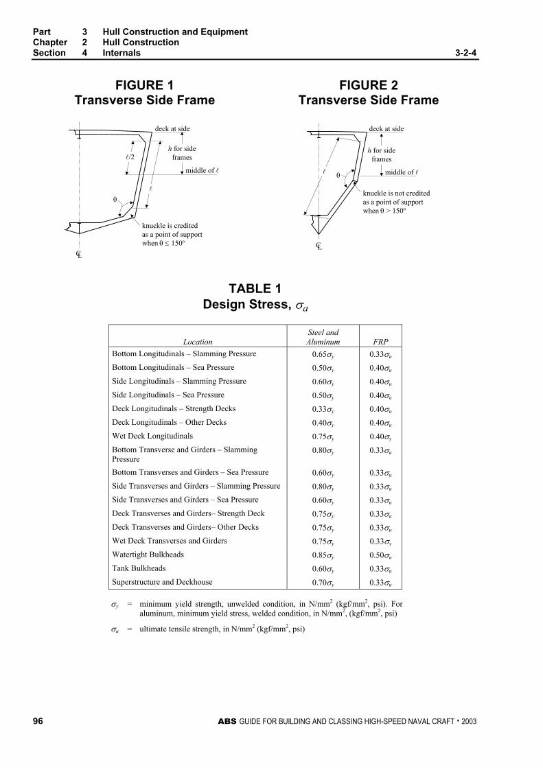
Part 3 Hull Construction and Equipment Chapter 2 Hull Construction Section 4 Internals 3-2-4
96 ABS GUIDE FOR BUILDING AND CLASSING HIGH-SPEED NAVAL CRAFT . 2003
FIGURE 1 Transverse Side Frame
FIGURE 2 Transverse Side Frame
h for sideframesl/2
l
deck at side
middle of l
knuckle is creditedas a point of supportwhen θ ≤ 150º
θ
CL
h for sideframes
deck at side
middle of l
CL
θ
knuckle is not creditedas a point of supportwhen θ > 150º
l
TABLE 1 Design Stress, σa
Location
Steel and Aluminum
FRP
Bottom Longitudinals – Slamming Pressure 0.65σy 0.33σu Bottom Longitudinals – Sea Pressure 0.50σy 0.40σu Side Longitudinals – Slamming Pressure 0.60σy 0.40σu Side Longitudinals – Sea Pressure 0.50σy 0.40σu Deck Longitudinals – Strength Decks 0.33σy 0.40σu
Deck Longitudinals – Other Decks 0.40σy 0.40σu
Wet Deck Longitudinals 0.75σy 0.40σy Bottom Transverse and Girders – Slamming Pressure
0.80σy 0.33σu
Bottom Transverses and Girders – Sea Pressure 0.60σy 0.33σu
Side Transverses and Girders – Slamming Pressure 0.80σy 0.33σu Side Transverses and Girders – Sea Pressure 0.60σy 0.33σu Deck Transverses and Girders– Strength Deck 0.75σy 0.33σu Deck Transverses and Girders– Other Decks 0.75σy 0.33σu Wet Deck Transverses and Girders 0.75σy 0.33σy Watertight Bulkheads 0.85σy 0.50σu Tank Bulkheads 0.60σy 0.33σu Superstructure and Deckhouse 0.70σy 0.33σu
σy = minimum yield strength, unwelded condition, in N/mm2 (kgf/mm2, psi). For
aluminum, minimum yield stress, welded condition, in N/mm2, (kgf/mm2, psi)
σu = ultimate tensile strength, in N/mm2 (kgf/mm2, psi)
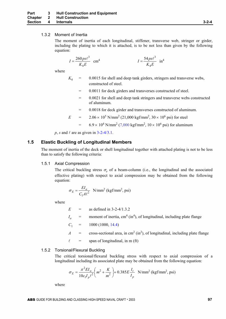
Part 3 Hull Construction and Equipment Chapter 2 Hull Construction Section 4 Internals 3-2-4
ABS GUIDE FOR BUILDING AND CLASSING HIGH-SPEED NAVAL CRAFT . 2003 97
1.3.2 Moment of Inertia The moment of inertia of each longitudinal, stiffener, transverse web, stringer or girder, including the plating to which it is attached, is to be not less than given by the following equation:
EKpsI4
3260 l= cm4
EKpsI4
354 l= in4
where
K4 = 0.0015 for shell and deep tank girders, stringers and transverse webs, constructed of steel.
= 0.0011 for deck girders and transverses constructed of steel.
= 0.0021 for shell and deep tank stringers and transverse webs constructed of aluminum.
= 0.0018 for deck girder and transverses constructed of aluminum.
E = 2.06 × 10⁵ N/mm2 (21,000 kgf/mm2, 30 × 106 psi) for steel
= 6.9 × 10⁴ N/mm2 (7,000 kgf/mm2, 10 × 106 psi) for aluminum
p, s and l are as given in 3-2-4/3.1.
1.5 Elastic Buckling of Longitudinal Members The moment of inertia of the deck or shell longitudinal together with attached plating is not to be less than to satisfy the following criteria:
1.5.1 Axial Compression The critical buckling stress σe of a beam-column (i.e., the longitudinal and the associated effective plating) with respect to axial compression may be obtained from the following equation:
21 lACEIa
E =σ N/mm2 (kgf/mm2, psi)
where
E = as defined in 3-2-4/1.3.2
Ia = moment of inertia, cm4 (in4), of longitudinal, including plate flange
C1 = 1000 (1000, 14.4)
A = cross-sectional area, in cm2 (in2), of longitudinal, including plate flange
l = span of longitudinal, in m (ft)
1.5.2 Torsional/Flexural Buckling The critical torsional/flexural buckling stress with respect to axial compression of a longitudinal including its associated plate may be obtained from the following equation:
p
t
p
wE I
IEmKm
IcEI 385.0
10 22
21
2+
+=
l
πσ N/mm2 (kgf/mm2, psi)
where

Part 3 Hull Construction and Equipment Chapter 2 Hull Construction Section 4 Internals 3-2-4
98 ABS GUIDE FOR BUILDING AND CLASSING HIGH-SPEED NAVAL CRAFT . 2003
K = c2 wEI
C4
4
πl
m = 1 for 0 < K ≤ 4
2 for 4 < K ≤ 36
3 for 36 < K ≤ 144
4 for 144 < K ≤ 400
E = as defined in 3-2-4/1.3.2
c2 = 106 (106, 20736)
It = St. Venant’s moment of inertia, in cm4 (in4), of profile (without plate flange)
= c3 3
3wwth for flat bars (slabs)
= c3 31
−+
f
fffww b
ttbth 63.0133 for flanged profiles
c3 = 10-4 (10-4, 1.0)
Ip = polar moment of inertia, in cm4 (in4), of profile about connection of stiffener to plate
= c3 3
3wwth for flat bars (slabs)
= c3
+ ffw
ww tbhth 23
3
for flanged profiles
Iw = warping constant, in cm6 (in6), of profile about connection of stiffener to plate
= c4 36
33wwth for flat bars (slabs)
= c4
12
23wff hbt
for “Tee” profiles
= c4 2
23
)(12 wf
wf
hb
hb
+ [tf(bf
2 + 2bfhw + 4hw2) + 3twbfhw]
c4 = 10-6 (10-6, 1.0)
hw = web height, in mm (in.)
tw = web thickness, in mm (in.)
bf = flange width, in mm (in.)
for angles and bulb profiles
Part 3 Hull Construction and Equipment Chapter 2 Hull Construction Section 4 Internals 3-2-4
ABS GUIDE FOR BUILDING AND CLASSING HIGH-SPEED NAVAL CRAFT . 2003 99
l = span of member, in m (ft)
s = spacing of member, in mm (in.)
C = spring stiffness exerted by supporting plate panel
=
+
w
spwp
spp
st
thks
Etk
3
33.113
N (kgf, lbf)
kp = 1 – ηp, not to be taken less than zero. For flanged profiles kp need not be taken less than 0.1.
tp = plate thickness, in mm (in.)
ηp = Ep
a
σσ
σa = calculated compressive stress. For longitudinals, members see 3-2-4/1.5.4
σEp = elastic buckling stress of supporting plate as calculated in 3-2-3/1.5.1(a)
1.5.3 Critical Buckling Stress The critical buckling stress in compression, σc, is determined as follows:
σc = σE when σE ≤ 0.5σy
=
−
E
yy σ
σσ
41 when σE > 0.5σy
where
σy = yield strength of material, in N/mm2 (kgf/mm2, psi)
Note: Generally the unwelded yield strength may be used, but due account should be made for critical or extensive weld zones.
σE = ideal elastic buckling stress calculated in 3-2-3/1.5.1
1.5.4 Calculated Compressive Stress
σa = c5 IyM t )(
N/mm2 (kgf/mm2, psi)
where
σa = working compressive stress in panel being considered, N/mm2 (kgf/mm2, psi), but generally not less than the following:
= A
RSMSM
QC1 N/mm2 (kgf/mm2, psi)
c5 = 105 (105, 322, 560)
Mt = maximum total bending moment as given in 3-2-1/1.1.2(e), kN-m (tf-m, Ltf-ft)
Part 3 Hull Construction and Equipment Chapter 2 Hull Construction Section 4 Internals 3-2-4
100 ABS GUIDE FOR BUILDING AND CLASSING HIGH-SPEED NAVAL CRAFT . 2003
y = vertical distance, in m (ft), from the neutral axis to the considered location.
I = moment of inertia of the hull girder, cm4 (in4)
C1 = 175 N/mm2 (17.84 kgf/mm2, 25,380 psi)
SMR = hull girder section modulus, as required in Section 3-2-1, cm2-m (in2-ft)
SMA = section modulus of the hull girder at the location being considered, cm2-m (in2-ft)
Q = material factor as given in 3-2-1/1.1
1.5.5 Design Buckling Stress The design buckling stress, σc, is to be such that:
σc ≥ βσa
where
β = 1.10 for the web plating of members
= 1.20 for overall buckling of members
1.5.6 Web and Flange Buckling Local buckling is considered satisfactory provided the following proportions are not exceeded.
1.5.6(a) Flat bars, Outstanding Face Bars and Flanges
dw/tw ≤ 0.5(E/σy)1/2 C2
1.5.6(b) Built-up Sections, Angle Bars and Tee Bars
dw/tw ≤ 1.5(E/σy)1/2 C2
1.5.6(c) Bulb Plates
dw/tw ≤ 0.85(E/σy)1/2 C2
where
tw = total required thickness, in mm (in.)
dw = depth of the web, in mm (in.)
E = as defined in 3-2-4/1.3.2
σy = yield strength of material, in N/mm2 (kgf/mm2, psi)
Note: Generally the unwelded yield strength may be used, but due account should be made for critical or extensive weld zones.
C2 = 1 where σa > 0.80σy
= 0.80σy /σa where σa < 0.80σy, and σa is to be taken not less than 0.55σy.
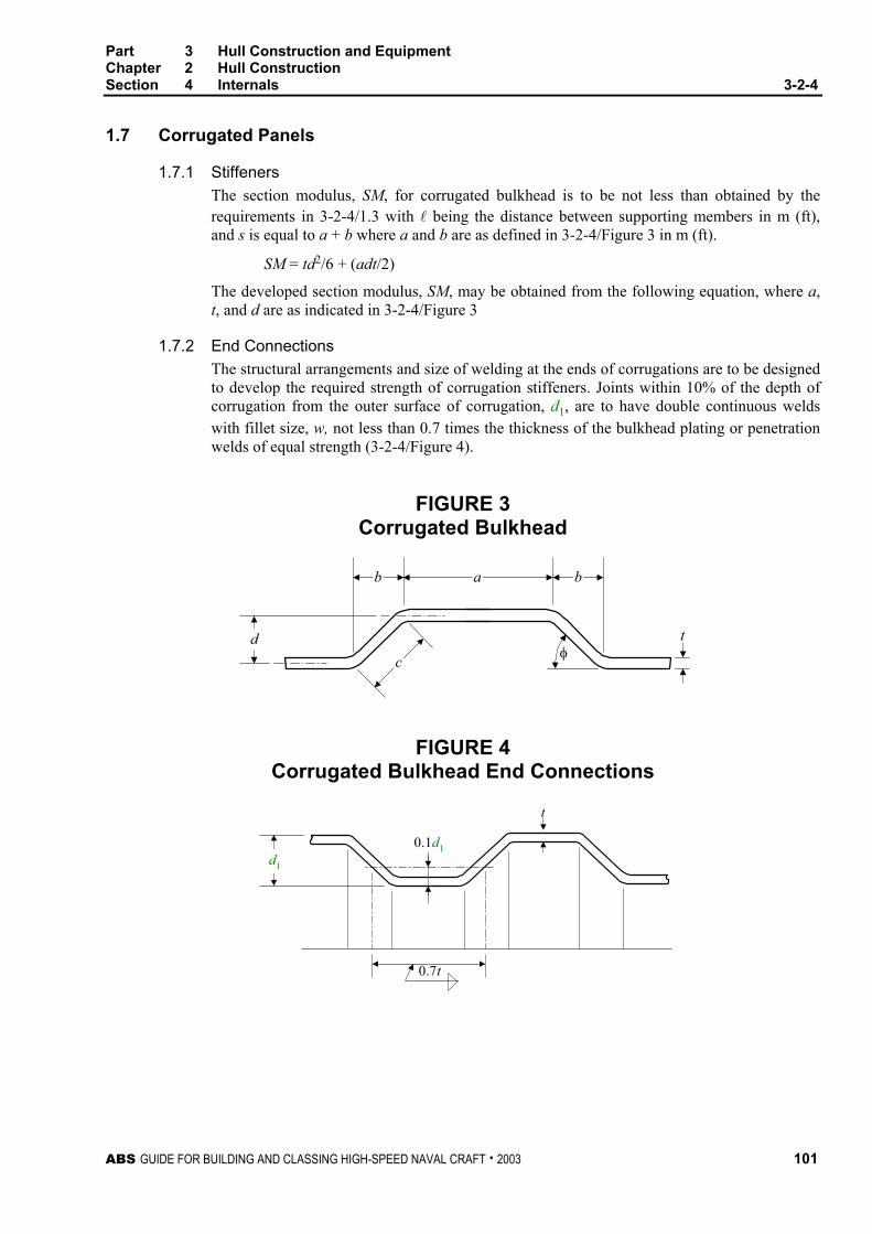
Part 3 Hull Construction and Equipment Chapter 2 Hull Construction Section 4 Internals 3-2-4
ABS GUIDE FOR BUILDING AND CLASSING HIGH-SPEED NAVAL CRAFT . 2003 101
1.7 Corrugated Panels
1.7.1 Stiffeners The section modulus, SM, for corrugated bulkhead is to be not less than obtained by the requirements in 3-2-4/1.3 with l being the distance between supporting members in m (ft), and s is equal to a + b where a and b are as defined in 3-2-4/Figure 3 in m (ft).
SM = td2/6 + (adt/2)
The developed section modulus, SM, may be obtained from the following equation, where a, t, and d are as indicated in 3-2-4/Figure 3
1.7.2 End Connections The structural arrangements and size of welding at the ends of corrugations are to be designed to develop the required strength of corrugation stiffeners. Joints within 10% of the depth of corrugation from the outer surface of corrugation, d1, are to have double continuous welds with fillet size, w, not less than 0.7 times the thickness of the bulkhead plating or penetration welds of equal strength (3-2-4/Figure 4).
FIGURE 3 Corrugated Bulkhead
tφ
dc
b a b
FIGURE 4 Corrugated Bulkhead End Connections
0.7t
0.1d1
t
d1
Part 3 Hull Construction and Equipment Chapter 2 Hull Construction Section 4 Internals 3-2-4
102 ABS GUIDE FOR BUILDING AND CLASSING HIGH-SPEED NAVAL CRAFT . 2003
1.9 Web Thickness The thickness of the webs of structural members is not to be less than determined by the following equation:
1.9.1 Webs 2/1
54.1
=
yw
w Etd
τ in general
= 1.152/1
y
Eτ
in slamming area
where
tw = total required thickness, in mm (in.)
dw = depth of the web, in mm (in.)
τy = minimum shear yield strength of steel or aluminum in the unwelded condition, N/mm2 (kgf/mm2, psi)
The web thickness is also not to be less than the following:
awdpstτ2
1000 l= mm
awdpstτ2
144 l= in.
where
t = total required thickness, in mm (in.)
p = design pressure, in kN/m2 (tf/m2, psi), as given in Section 3-2-2
s = width of shell or deck supported by the member, in m (ft)
l = length of member, in m (ft)
dw = depth of the web, in mm (in.)
τa = design shear stress, in N/mm2 (kgf/mm2, psi)
= 0.5τy for steel structure and 0.5τyw for aluminum structure. For bottom primary structure 0.75τy or 0.75τyw.
τy = minimum shear, unwelded condition, in N/mm2 (kgf/mm2, psi)
τyw = minimum shear yield strength welded condition, in N/mm2 (kgf/mm2, psi).
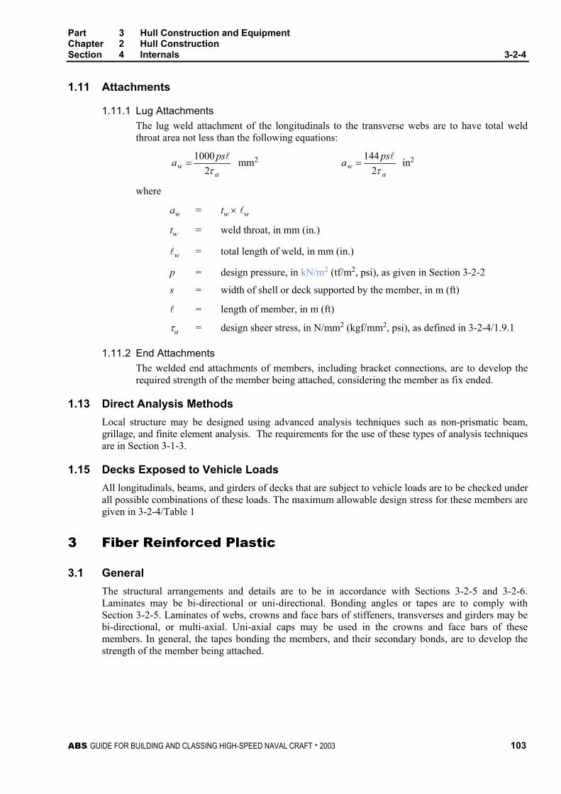
Part 3 Hull Construction and Equipment Chapter 2 Hull Construction Section 4 Internals 3-2-4
ABS GUIDE FOR BUILDING AND CLASSING HIGH-SPEED NAVAL CRAFT . 2003 103
1.11 Attachments
1.11.1 Lug Attachments The lug weld attachment of the longitudinals to the transverse webs are to have total weld throat area not less than the following equations:
aw
psaτ2
1000 l= mm2
aw
psaτ2
144 l= in2
where
aw = tw × lw
tw = weld throat, in mm (in.)
lw = total length of weld, in mm (in.)
p = design pressure, in kN/m2 (tf/m2, psi), as given in Section 3-2-2
s = width of shell or deck supported by the member, in m (ft)
l = length of member, in m (ft)
τa = design sheer stress, in N/mm2 (kgf/mm2, psi), as defined in 3-2-4/1.9.1
1.11.2 End Attachments The welded end attachments of members, including bracket connections, are to develop the required strength of the member being attached, considering the member as fix ended.
1.13 Direct Analysis Methods Local structure may be designed using advanced analysis techniques such as non-prismatic beam, grillage, and finite element analysis. The requirements for the use of these types of analysis techniques are in Section 3-1-3.
1.15 Decks Exposed to Vehicle Loads All longitudinals, beams, and girders of decks that are subject to vehicle loads are to be checked under all possible combinations of these loads. The maximum allowable design stress for these members are given in 3-2-4/Table 1
3 Fiber Reinforced Plastic
3.1 General The structural arrangements and details are to be in accordance with Sections 3-2-5 and 3-2-6. Laminates may be bi-directional or uni-directional. Bonding angles or tapes are to comply with Section 3-2-5. Laminates of webs, crowns and face bars of stiffeners, transverses and girders may be bi-directional, or multi-axial. Uni-axial caps may be used in the crowns and face bars of these members. In general, the tapes bonding the members, and their secondary bonds, are to develop the strength of the member being attached.

Part 3 Hull Construction and Equipment Chapter 2 Hull Construction Section 4 Internals 3-2-4
104 ABS GUIDE FOR BUILDING AND CLASSING HIGH-SPEED NAVAL CRAFT . 2003
3.3 Fiber Reinforcement The basic laminate given in Part 2, Chapter 6, or other approved laminates of glass, aramid, or carbon fiber, in mat, woven roving, cloth, knitted fabric, or non-woven uni-directional reinforcing plies may be used. The plies are in general to be layed-up parallel to the direction of the internal. The strength of the laminate in a direction perpendicular to the direction of the internal is in general not to be less than 25% of the warp strength except for the uni-directional caps of the flange or crown of the internal members. In way of continuous longitudinal members, the required section modulus, shear area and moment of inertia of transverse members are to be maintained by the shell or deck plating and that part of the transverse member that is continuous over the longitudinal member.
Where higher strength or higher modulus plies are used in the flange or crown of the internal, it may be advisable to provide similar higher strength, higher modulus local plies in the shell or deck plating, in the direction parallel to the internal to balance the strength and stiffness of the high strength and high modulus plies in the flange or crown of the internal.
3.5 Strength and Stiffness
3.5.1 Section Modulus The section modulus of each longitudinal, stiffener, transverse web and girder including the plating to which it is attached is to be not less than given by the following equation:
a
psSMσ
23.83 l×= cm3
a
psSMσ
2144 l×= in3
where p, s, l and σa are defined in 3-2-4/1.3.
Where the shell, deck or bulkhead plating, and the webs and flange and crown of the member are of different strength or elastic property plies, consideration is to be given to the effect of the different modulii plies in calculating the moment of inertia and section modulus; the required section modulus is to be considered for each different strength laminate of the member.
3.5.2 Moment of Inertia The moment of inertia of each longitudinal, stiffener, transverse web, stringer or girder, including the plating to which it is attached, is to be not less than given by the following equation:
EKpsI4
3260 l= cm4
EKpsI4
354 l= in4
where
K4 = 0.005 for shell and deep tank girders, stringers and transverse webs.
= 0.004 for deck girders and transverses.
= 0.010 for all other members.
E = tensile or compressive modulus, in N/mm2 (kgf/mm2, psi) representative of the basic value used in the moment of inertia calculation.
p, s and l are as given in 3-2-4/1.3.

Part 3 Hull Construction and Equipment Chapter 2 Hull Construction Section 4 Internals 3-2-4
ABS GUIDE FOR BUILDING AND CLASSING HIGH-SPEED NAVAL CRAFT . 2003 105
3.5.3 Shear Area The web area, A, of the member is to be not less than given by the following equation:
τ21000 lpsA = cm2
τ2144 lpsA = in2
where
A = net web area, in cm2 (in2), at location being considered τ = design shear stress, in N/mm2 (kgf/mm2, psi), to be taken not greater than
0.4τu τu = lesser of ultimate shear strength, in N/mm2 (kgf/mm2, psi), in either warp
or fill of the web laminate p, s and l are as given in 3-2-4/1.3. Consideration will be given to determining the web area using more detailed methods of determining the shear stress in the web at the neutral axis of the member.
3.7 Proportions The thickness of webs and flanges are to be in accordance with Section 3-2-6.
3.9 Buckling
3.9.1 Single Skin Laminate Where single skin laminate members are subject to in-plane compressive loading likely to cause axial overall or local buckling, design calculations are to be submitted to show the margin against buckling failure.
3.9.2 Sandwich Laminates Where sandwich laminate members are subject to in-plane compressive loading, likely to cause axial overall or local buckling of the sandwich, or of the sandwich skins, design calculations are to be submitted to show the margin against buckling failure.
5 Stanchions
5.1 General The structure under stanchions is to be of sufficient strength to distribute the loads effectively. Stanchions above are to be arranged directly over stanchions below wherever possible; where this is not possible, effective means are to be provided for transmitting the loads to the structure below. Stanchions in double bottoms and under the tops of deep tanks are to be metal and solid in cross section. Stanchions are in general not to be used in the bottom or double bottom structures where subject to high impact loads in service.
5.3 Stanchion Analysis The load, W, on a given stanchion is to be developed from the end reaction from the girders that the stanchion supports. These end reactions are to be developed considering the design pressure for the deck in which they are located plus any point loads from stanchions located on the girder. When cascading the stanchion loads through the structure, the analysis is to consider the load from the deck directly above the stanchion plus the loads from all complete decks and one-half the load from all partial or deckhouse decks. The requirement in 3-2-4/5.5 is given for a simple stanchion that will only need to support the deck directly above. In general, stanchions are to have sectional area not less than 1.015W cm2 (0.16W in2) where the stanchions are subject to tension loads.

Part 3 Hull Construction and Equipment Chapter 2 Hull Construction Section 4 Internals 3-2-4
106 ABS GUIDE FOR BUILDING AND CLASSING HIGH-SPEED NAVAL CRAFT . 2003
5.5 Stanchion Load The load on a stanchion is to be obtained from the following equation:
W = pbs kN (tf) W = 0.064 pbs Ltf
where
W = load, in kN (tf, Ltf)
b = mean breadth, in m (ft), of area supported
s = mean length, in m (ft), of area supported
p = design pressure, in kN/m2 (tf/m2, psi), given in Section 3-2-2
5.7 Permissible Load The load a stanchion may carry is to be equal to or greater than the load on the stanchion obtained in 3-2-4/5.3. This permissible load is to be obtained from the following equations:
5.7.1 Ordinary Strength Steel Stanchions Wa = (12.09 − 0.0444l/r) A kN
Wa = (1.232 − 0.00452l/r) A tf
Wa = (7.83 − 0.345l/r) A Ltf
Refer to 3-2-8/3.1 of the Rules for Building and Classing Steel Vessels for high strength steel.
5.7.2 Aluminum-Alloy Stanchions (1 January 2004) Wa = (10.00 − 0.0582l/r) Aσy /165 kN
Wa = (1.02 − 0.00593l/r) Aσy /17 tf
Wa = (6.49 − 0.452l/r) Aσy /24000 Ltf
where Wa = permissible load, in kN (tf, Ltf) r = least radius of gyration of stanchion, in cm (in.) A = area of stanchion, in cm2 (in2) l = unsupported length of stanchion, in m (ft) σy = minimum yield strength of welded aluminum under consideration, in
N/mm2 (kgf/m2, psi),
The adoption of aluminum test values higher than given in Part 2, Chapter 5 will be subject to special consideration.
5.9 FRP Stanchions FRP stanchions will be subject to special consideration.
5.11 Support by Bulkheads Bulkheads supporting girders or bulkheads fitted in lieu of stanchions are to be stiffened to provide support not less effective than required for stanchions.
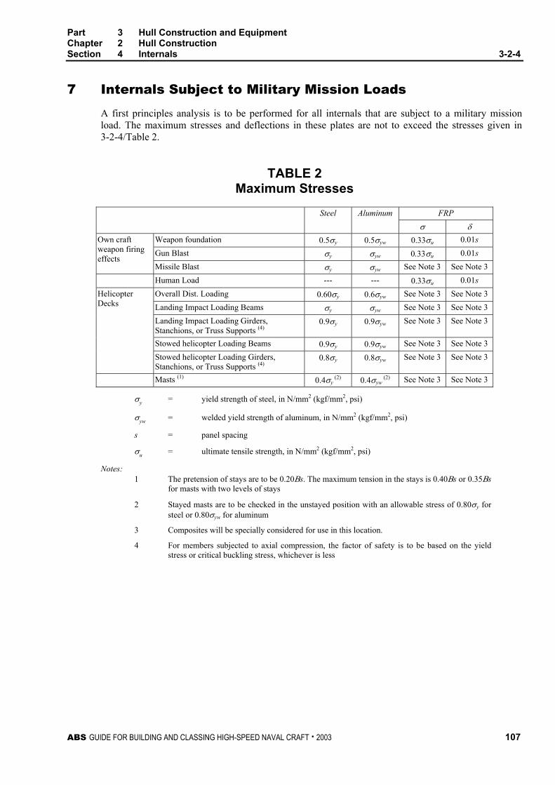
Part 3 Hull Construction and Equipment Chapter 2 Hull Construction Section 4 Internals 3-2-4
ABS GUIDE FOR BUILDING AND CLASSING HIGH-SPEED NAVAL CRAFT . 2003 107
7 Internals Subject to Military Mission Loads
A first principles analysis is to be performed for all internals that are subject to a military mission load. The maximum stresses and deflections in these plates are not to exceed the stresses given in 3-2-4/Table 2.
TABLE 2 Maximum Stresses
FRP Steel Aluminum σ δ
Weapon foundation 0.5σy 0.5σyw 0.33σu 0.01s Gun Blast σy σyw 0.33σu 0.01s
Own craft weapon firing effects
Missile Blast σy σyw See Note 3 See Note 3 Human Load --- --- 0.33σu 0.01s
Overall Dist. Loading 0.60σy 0.6σyw See Note 3 See Note 3 Landing Impact Loading Beams σy σyw See Note 3 See Note 3 Landing Impact Loading Girders, Stanchions, or Truss Supports (4)
0.9σy 0.9σyw See Note 3 See Note 3
Stowed helicopter Loading Beams 0.9σy 0.9σyw See Note 3 See Note 3
Helicopter Decks
Stowed helicopter Loading Girders, Stanchions, or Truss Supports (4)
0.8σy 0.8σyw See Note 3 See Note 3
Masts (1) 0.4σy (2) 0.4σyw
(2) See Note 3 See Note 3
σy = yield strength of steel, in N/mm2 (kgf/mm2, psi)
σyw = welded yield strength of aluminum, in N/mm2 (kgf/mm2, psi)
s = panel spacing
σu = ultimate tensile strength, in N/mm2 (kgf/mm2, psi)
Notes: 1 The pretension of stays are to be 0.20Βs. The maximum tension in the stays is 0.40Βs or 0.35Βs
for masts with two levels of stays
2 Stayed masts are to be checked in the unstayed position with an allowable stress of 0.80σy for steel or 0.80σyw for aluminum
3 Composites will be specially considered for use in this location.
4 For members subjected to axial compression, the factor of safety is to be based on the yield stress or critical buckling stress, whichever is less

This Page Intentionally Left Blank

ABS GUIDE FOR BUILDING AND CLASSING HIGH-SPEED NAVAL CRAFT . 2003 109
P A R T
3 C H A P T E R 2 Hull Structures and Arrangements
S E C T I O N 5 Hull Structural Arrangement
1 Structural Arrangement – All Materials
1.1 Framing, Webs, Girders, and Non-tight Structural Bulkheads
1.1.1 General The shell, main deck, and the sides and tops of long superstructures are in general to be longitudinally framed; depending on craft length, speed and structural stability, craft may also be transversely framed. On transversely framed craft, it is to be clearly indicated that the structure has a continuous load path that eliminates hard spots on unsupported structure.
Bulkheads, partial bulkheads or web frames are to be arranged in the main hull and in long superstructures or deckhouses to provide effective transverse rigidity. Bulkheads or deep web frames are to be provided in the main hull under the ends of superstructures or deckhouses.
Longitudinal frames are to be supported by transverse web frames, transverse bulkheads or other transverse structure. For craft over 61 m (200 ft) in length, or on craft where the longitudinal stiffeners need to be included in the offered longitudinal strength calculation to meet the requirements in 3-2-1/1, the longitudinals are to be continuous in way of transverse supporting members, including transverse bulkheads. All other craft may have longitudinal members intercostal to the transverse bulkheads provided that continuity of strength and end fixity are maintained in accordance with 3-1-2/5.9 and 3-2-5/1.1.2. Craft that are under 30.5 m (100 ft) in length, and where the longitudinal stiffeners do not need to be included in the offered longitudinal strength calculation to meet the requirements in 3-2-1/1, may have longitudinal stiffeners that are intercostal to the transverse supporting members and bulkheads providing that continuity of strength and end fixity are maintained in accordance with 3-1-2/5.9 and 3-2-5/1.1.2. With transverse framing, deck and bottom girders are to be provided. Girders may be intercostal at transverse bulkheads provided continuity of strength is maintained and end fixity is provided in accordance with 3-1-2/5.9 and 3-2-5/1.1.2.
Transverses are to be arranged as continuous web rings and girders are to be aligned with stiffeners at bulkheads. Alternative arrangements that provide fixity at the ends of transverses and girders will be specially considered.
1.1.2 Attachments and Stiffening At supporting members, the attachment of all internal structural members is to provide end fixity and effective load transmission. Special consideration will be given to reduced end fixity where the alternative structure has equivalent strength.
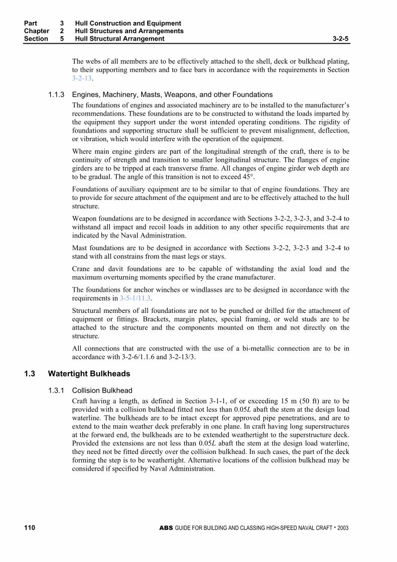
Part 3 Hull Construction and Equipment Chapter 2 Hull Structures and Arrangements Section 5 Hull Structural Arrangement 3-2-5
110 ABS GUIDE FOR BUILDING AND CLASSING HIGH-SPEED NAVAL CRAFT . 2003
The webs of all members are to be effectively attached to the shell, deck or bulkhead plating, to their supporting members and to face bars in accordance with the requirements in Section 3-2-13.
1.1.3 Engines, Machinery, Masts, Weapons, and other Foundations The foundations of engines and associated machinery are to be installed to the manufacturer’s recommendations. These foundations are to be constructed to withstand the loads imparted by the equipment they support under the worst intended operating conditions. The rigidity of foundations and supporting structure shall be sufficient to prevent misalignment, deflection, or vibration, which would interfere with the operation of the equipment.
Where main engine girders are part of the longitudinal strength of the craft, there is to be continuity of strength and transition to smaller longitudinal structure. The flanges of engine girders are to be tripped at each transverse frame. All changes of engine girder web depth are to be gradual. The angle of this transition is not to exceed 45°.
Foundations of auxiliary equipment are to be similar to that of engine foundations. They are to provide for secure attachment of the equipment and are to be effectively attached to the hull structure.
Weapon foundations are to be designed in accordance with Sections 3-2-2, 3-2-3, and 3-2-4 to withstand all impact and recoil loads in addition to any other specific requirements that are indicated by the Naval Administration.
Mast foundations are to be designed in accordance with Sections 3-2-2, 3-2-3 and 3-2-4 to stand with all constrains from the mast legs or stays.
Crane and davit foundations are to be capable of withstanding the axial load and the maximum overturning moments specified by the crane manufacturer.
The foundations for anchor winches or windlasses are to be designed in accordance with the requirements in 3-5-1/11.3.
Structural members of all foundations are not to be punched or drilled for the attachment of equipment or fittings. Brackets, margin plates, special framing, or weld studs are to be attached to the structure and the components mounted on them and not directly on the structure.
All connections that are constructed with the use of a bi-metallic connection are to be in accordance with 3-2-6/1.1.6 and 3-2-13/3.
1.3 Watertight Bulkheads
1.3.1 Collision Bulkhead Craft having a length, as defined in Section 3-1-1, of or exceeding 15 m (50 ft) are to be provided with a collision bulkhead fitted not less than 0.05L abaft the stem at the design load waterline. The bulkheads are to be intact except for approved pipe penetrations, and are to extend to the main weather deck preferably in one plane. In craft having long superstructures at the forward end, the bulkheads are to be extended weathertight to the superstructure deck. Provided the extensions are not less than 0.05L abaft the stem at the design load waterline, they need not be fitted directly over the collision bulkhead. In such cases, the part of the deck forming the step is to be weathertight. Alternative locations of the collision bulkhead may be considered if specified by Naval Administration.

Part 3 Hull Construction and Equipment Chapter 2 Hull Structures and Arrangements Section 5 Hull Structural Arrangement 3-2-5
ABS GUIDE FOR BUILDING AND CLASSING HIGH-SPEED NAVAL CRAFT . 2003 111
1.3.2 Engine Room The engine room is to be enclosed by watertight bulkheads extending to the main weather deck.
1.3.3 Chain Locker (1 January 2004) For craft with length L (as defined in 3-1-1/3) greater than 24 meters (79 feet), chain lockers and chain pipes are to be made watertight up to the weather deck. The arrangements are to be such that accidental flooding of the chain locker cannot result in damage to auxiliaries or equipment necessary for the proper operation of the craft nor in successive flooding into other spaces.
Where means of access into chain lockers are provided, they are to be closed by a substantial cover secured by closely spaced bolts. Doors are not permitted.
For closure of chain pipes, see 3-2-9/21.7.
The arrangements on craft that are not subject to the International Convention on Load Lines or its Protocol may be specially considered.
1.5 Tanks The arrangements of all tanks, their intended service, and the heights of the overflow pipes are to be indicated clearly on the drawings submitted for approval.
Where potable water tanks are fitted, water closets are not to be installed on top of the tanks nor are soil lines to run over the tops of the tanks. Pipes containing non-potable liquids are not to be run through the tanks. Attention is directed to the requirements of the Naval Administration that might govern the location, construction or design of such tanks.
Baffle or swash plates are to be provided. Special consideration may be given for the omission of baffle or swash plates providing the effects of fluid slamming on the plate are considered.
Scantlings of pressurized tanks will be subject to special consideration.
All tanks and void spaces are to be accessible for inspection and repair.
1.7 Decks Where a deck is stepped or has a break, suitable scarphing or brackets are to be provided at the side shell.
Decks passing into superstructures within the 0.5L amidships are to be increased in way of the break. See 3-2-1/1.2 and 3-2-1//5.
1.9 Means of Escape Unless otherwise specified by the Naval Administration, all main hull spaces accessed by the passengers or military personnel, including accommodations, are to have two means of escape to the main weather deck. These escapes are to be located as far apart as practicable and are to be operable from both sides. All escape routes are to be readily accessible and unobstructed.
Size and materials for stairs, vertical ladders, hatches, doors, etc. that are used for escape measures are to be specified by the Naval Administration.
1.11 Double Bottoms The length and extent of double bottoms are to be determined by the Naval Administration.
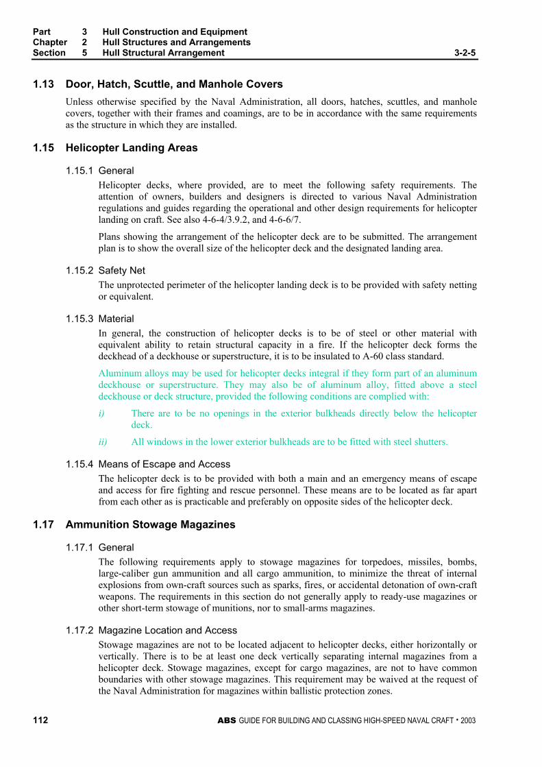
Part 3 Hull Construction and Equipment Chapter 2 Hull Structures and Arrangements Section 5 Hull Structural Arrangement 3-2-5
112 ABS GUIDE FOR BUILDING AND CLASSING HIGH-SPEED NAVAL CRAFT . 2003
1.13 Door, Hatch, Scuttle, and Manhole Covers Unless otherwise specified by the Naval Administration, all doors, hatches, scuttles, and manhole covers, together with their frames and coamings, are to be in accordance with the same requirements as the structure in which they are installed.
1.15 Helicopter Landing Areas
1.15.1 General Helicopter decks, where provided, are to meet the following safety requirements. The attention of owners, builders and designers is directed to various Naval Administration regulations and guides regarding the operational and other design requirements for helicopter landing on craft. See also 4-6-4/3.9.2, and 4-6-6/7.
Plans showing the arrangement of the helicopter deck are to be submitted. The arrangement plan is to show the overall size of the helicopter deck and the designated landing area.
1.15.2 Safety Net The unprotected perimeter of the helicopter landing deck is to be provided with safety netting or equivalent.
1.15.3 Material In general, the construction of helicopter decks is to be of steel or other material with equivalent ability to retain structural capacity in a fire. If the helicopter deck forms the deckhead of a deckhouse or superstructure, it is to be insulated to A-60 class standard.
Aluminum alloys may be used for helicopter decks integral if they form part of an aluminum deckhouse or superstructure. They may also be of aluminum alloy, fitted above a steel deckhouse or deck structure, provided the following conditions are complied with:
i) There are to be no openings in the exterior bulkheads directly below the helicopter deck.
ii) All windows in the lower exterior bulkheads are to be fitted with steel shutters.
1.15.4 Means of Escape and Access The helicopter deck is to be provided with both a main and an emergency means of escape and access for fire fighting and rescue personnel. These means are to be located as far apart from each other as is practicable and preferably on opposite sides of the helicopter deck.
1.17 Ammunition Stowage Magazines
1.17.1 General The following requirements apply to stowage magazines for torpedoes, missiles, bombs, large-caliber gun ammunition and all cargo ammunition, to minimize the threat of internal explosions from own-craft sources such as sparks, fires, or accidental detonation of own-craft weapons. The requirements in this section do not generally apply to ready-use magazines or other short-term stowage of munitions, nor to small-arms magazines.
1.17.2 Magazine Location and Access Stowage magazines are not to be located adjacent to helicopter decks, either horizontally or vertically. There is to be at least one deck vertically separating internal magazines from a helicopter deck. Stowage magazines, except for cargo magazines, are not to have common boundaries with other stowage magazines. This requirement may be waived at the request of the Naval Administration for magazines within ballistic protection zones.

Part 3 Hull Construction and Equipment Chapter 2 Hull Structures and Arrangements Section 5 Hull Structural Arrangement 3-2-5
ABS GUIDE FOR BUILDING AND CLASSING HIGH-SPEED NAVAL CRAFT . 2003 113
1.17.3 Magazine Requirements No equipment is to be located within a magazine. Distributive systems are not to penetrate the boundaries of magazines except for those directly serving that magazine. Projectiles are not to be stowed in magazines containing powder cartridges or detonators, and vice-versa. Magazines are to have securing systems for all munitions adequate to prevent movement under all ship motions. Munitions are to have an air gap of at least 2 inches between the stowage stack and adjacent plating or sheathing. No cast iron or semi-steel is to be used for magazine equipment or stowage devices.
1.19 Arrangements for the Protection Against Own-Craft Weapons-Firing Effects
1.19.1 General Craft structures, systems and personnel are to be protected against the effects of firing its own weapons, specifically guns and missiles (this does not include temporarily mounted small-caliber guns or portable missiles). The blast zones consist of two areas. Direct blast areas are those which lie in the direct line of impingement by the exhaust stream of the missile or near the muzzle of the gun. Reflected blast areas are those areas onto which the exhaust stream or muzzle blast is deflected after impinging on a deck or bulkhead in the direct blast areas.
1.19.2 Hull Fittings The following items may be installed in the blast areas without shielding: flush-type including ramp low profile hatches and scuttles, portable lifelines and stanchions, bitts, chocks, fairleads, and rubber scuppers. Other items composed only of metallic materials may be installed in reflected blast areas without shielding.
Benchmarks in direct blast areas are to be equipped with steel covers. Recessed benchmarks are to be protected with flush deck covers and protruding benchmarks are to be protected with portable steel covers.
1.19.3 Requirements for Blast Shields Shields are to be provided with adequate rigidity by edge stiffening or other stiffening where needed. In reflected blast areas shields are to enclose the protected item with the open side facing away from the launcher. Blast shields are to be steel with a minimum thickness of 3 mm, or an equivalent heat-resistant material. Steel shields are to be attached to the deck or bulkhead by welding.
Shields are to be configured to present an oblique impingement surface to deflect the exhaust stream and to preclude the deflection of blast onto other equipment.
Shields are not to interfere with weapons handling or be a hazard to personnel. Shields are to have rounded corners and edges.
1.19.4 Personal Protection Red danger lights and labels are to be installed at doors and hatches which provide access into blast zones.

Part 3 Hull Construction and Equipment Chapter 2 Hull Structures and Arrangements Section 5 Hull Structural Arrangement 3-2-5
114 ABS GUIDE FOR BUILDING AND CLASSING HIGH-SPEED NAVAL CRAFT . 2003
3 Structural Arrangements – Additional Requirements for Steel and Aluminum Alloys
3.1 Shell Plating The bottom shell plating is to extend to the chine or upper turn of bilge. In general, the side shell is to be of the same thickness from its lower limit to the gunwale. Increases in thickness and additional stiffening are required in way of skegs, shaft struts, hawse pipes etc. Where a bow thruster tube is fitted to be in accordance with the requirements in 3-2-3/1.7.
5 Structural Arrangements – Additional Requirements for Fiber Reinforced Plastic Hulls
5.1 Tanks In fiber reinforced plastic construction, non-integral tanks are to be used whenever possible. When integral tanks are used they are to be of single skin construction; the only exception is the tank top plating can be of sandwich construction. No stiffeners within integral tanks are to penetrate the tank boundaries. No gasoline tanks, or tanks containing petroleum products with flash points less than 60°C (150°F) are to be fitted integrally. The design and arrangements of oil fuel tanks is to be such that there is no exposed horizontal section at the bottom that could be exposed to a fire. Other fire protection arrangements for oil fuel tanks will be specially considered. For details of fire protection requirements see Section 3-4-1.
All internal surfaces of FRP tanks are to be covered with chopped strand mat weighing at least 600 g/m2 (2 oz/ft2). This covering is to be in addition to the scantlings required by this Guide. A suitable coating is to be applied to this covering to prevent the contents of the tank from impregnating the surrounding laminates. The sides, tops, and baffles of integral tanks are to have all connections taped on both sides. Fresh water tanks are to be coated with a non-toxic and non-tainting coat of resin that is recommended by the resin manufacturer for potable water tanks. Where outfit items are to be laminated to the tank surface, the heavy coating of resin is to be applied afterwards and the laminated brackets sealed to prevent the ingress of moisture. The scantlings of integral oil fuel and water tanks are to be in accordance with Sections 3-2-3 and 3-2-4. Integral tanks are to be tested in accordance with 3-6-1/Table 1.

ABS GUIDE FOR BUILDING AND CLASSING HIGH-SPEED NAVAL CRAFT . 2003 115
P A R T
3 C H A P T E R 2 Hull Structures and Arrangements
S E C T I O N 6 Arrangement, Structural Details and Connections
1 Structural Details
1.1 Aluminum and Steel
1.1.1 General Structural details are to be designed and constructed to minimize hard spots, notches and other structural discontinuities. Openings in webs, girders and other structural internal members are to be arranged clear of concentrated loads or areas of high stresses; slots in transverses and girders for longitudinals or beams in such locations are to be fitted with collars. Care is to be taken to ensure structural continuity; sharp corners and abrupt changes in section are to be avoided; toes of brackets and ends of members are not to terminate on plating without attachment to an adjacent member, unless specially approved.
1.1.2 Longitudinals Deck, bottom and inner bottom longitudinals are in general to be continuous unless specially approved otherwise, but in way of bulkheads they may be intercostal provided continuity of strength and end fixity are maintained by the end brackets. The ends of all internal structural members are to provide end-fixity and load transmission to the supporting member. Departures from this may be considered where the alternative structure has equivalent strength. See 3-2-5/1
1.1.3 Girders and Transverses Girders and transverses are to have depths not less than twice the depth of slots for longitudinals and beams or other openings. Transverses are to be arranged as continuous web rings, girders are to be aligned with stiffeners at bulkheads, alternative arrangements that provide fixity at the ends of transverses and girders will be specially considered.
1.1.4 Openings Access and lightening holes with suitably radiused corners are to be arranged as necessary and clear of areas of load concentration or high stresses. Their depths and lengths are generally not to exceed respectively, 0.5 and 0.75 the depth of the members.

Part 3 Hull Construction and Equipment Chapter 2 Hull Structures and Arrangements Section 6 Arrangement, Structural Details and Connections 3-2-6
116 ABS GUIDE FOR BUILDING AND CLASSING HIGH-SPEED NAVAL CRAFT . 2003
1.1.5 Limber Hole Drains or limber holes are to be provided in non-tight structure to prevent the accumulation of liquids. Holes are to be located to ensure complete drainage of all non-tight voids, bays, or pockets formed by structure. The holes are not to be located at points of high stress, such as the intersection of members. Limber holes are to be half round at the edge, or round if not at the edge, of the structure that is to be drained. The diameter of drain or limber hole is not to be greater than 20% of the depth of the member.
1.1.6 Bi-metallic Connections In aluminum construction, where bi-metallic connections are unavoidable, suitable insulation, such as gaskets, washers, sleeves, and bushings, are to be provided. The faying surfaces between mechanically fastened metal components, except machinery foundation shims, are to be protected by the use of a bedding compound. Stainless steel fasteners may be joined directly. See also 3-2-13/3
1.3 Fiber Reinforced Plastic
1.3.1 General Structural continuity is to be maintained and where changes in thickness or structural section occur, they are to be gradual to prevent notches, hard spots and other structural discontinuities. The requirements of 3-2-6/1.3.4 and 3-2-6/1.3.5, below, and of 3-2-6/3 and 3-2-6/5 are for the basic laminate given in Part 2, Chapter 6. Special consideration will be given where other laminates or resins are used. The ends of all internal structural members are to provide end-fixity and load transmission to the supporting member. Departures from this may be considered where the alternative structure has equivalent strength.
1.3.2 Changes in Laminate Thickness A gradual taper is to be used for all changes in laminate thickness. Where the construction changes from sandwich laminate to a solid laminate, the thickness of the core material is in general, to be reduced by a gradual taper of not less than 2:1.
1.3.3 Openings, Holes and Raw Edges Access and lightening holes with suitably radiused corners are to be arranged as necessary and clear of areas of load concentration or high stresses. Their depths and lengths are generally not to exceed, respectively, 0.5 and 0.75 times the depths of the members. Air and limber holes are to be in accordance with 3-2-6/1.1.5.
All exposed edges in way of cuts or holes in FRP single-skin laminates are to be sealed with resin. Edges of sandwich panels and edges of holes in sandwich panels are to be covered with one ply of glass cloth lapped no less than 25 mm (1 in.) onto each face of the laminate. The cloth shall be completely saturated with resin.
Ferrules installed in sandwich panels or stiffeners for drains or wire penetrations are to be set in bedding compound.
All hatch openings are to be supported by a system of transverse and longitudinal stiffeners.
1.3.4 Piping and Wiring in Foam Piping or wiring passing through foam-filled spaces is to be installed in PVC tubing. The pipe is to be arranged such that water will not become trapped. The ends of the plastic tubing are to be joined to adjacent structure with resin impregnated mat. See 3-2-6/Figure 1
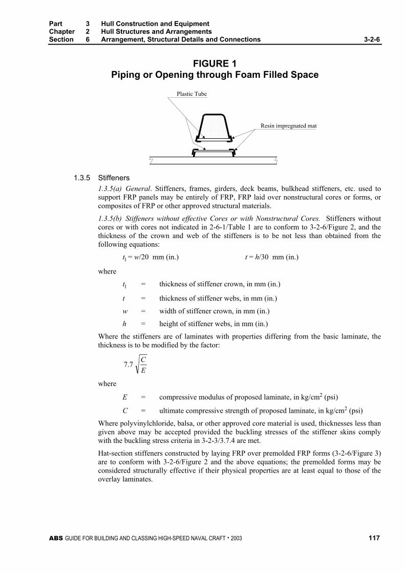
Part 3 Hull Construction and Equipment Chapter 2 Hull Structures and Arrangements Section 6 Arrangement, Structural Details and Connections 3-2-6
ABS GUIDE FOR BUILDING AND CLASSING HIGH-SPEED NAVAL CRAFT . 2003 117
FIGURE 1 Piping or Opening through Foam Filled Space
Plastic Tube
Resin impregnated mat
1.3.5 Stiffeners 1.3.5(a) General. Stiffeners, frames, girders, deck beams, bulkhead stiffeners, etc. used to support FRP panels may be entirely of FRP, FRP laid over nonstructural cores or forms, or composites of FRP or other approved structural materials.
1.3.5(b) Stiffeners without effective Cores or with Nonstructural Cores. Stiffeners without cores or with cores not indicated in 2-6-1/Table 1 are to conform to 3-2-6/Figure 2, and the thickness of the crown and web of the stiffeners is to be not less than obtained from the following equations:
tl = w/20 mm (in.) t = h/30 mm (in.)
where
tl = thickness of stiffener crown, in mm (in.)
t = thickness of stiffener webs, in mm (in.)
w = width of stiffener crown, in mm (in.)
h = height of stiffener webs, in mm (in.)
Where the stiffeners are of laminates with properties differing from the basic laminate, the thickness is to be modified by the factor:
EC7.7
where
E = compressive modulus of proposed laminate, in kg/cm2 (psi)
C = ultimate compressive strength of proposed laminate, in kg/cm2 (psi)
Where polyvinylchloride, balsa, or other approved core material is used, thicknesses less than given above may be accepted provided the buckling stresses of the stiffener skins comply with the buckling stress criteria in 3-2-3/3.7.4 are met.
Hat-section stiffeners constructed by laying FRP over premolded FRP forms (3-2-6/Figure 3) are to conform with 3-2-6/Figure 2 and the above equations; the premolded forms may be considered structurally effective if their physical properties are at least equal to those of the overlay laminates.

Part 3 Hull Construction and Equipment Chapter 2 Hull Structures and Arrangements Section 6 Arrangement, Structural Details and Connections 3-2-6
118 ABS GUIDE FOR BUILDING AND CLASSING HIGH-SPEED NAVAL CRAFT . 2003
FIGURE 2 Proportions of Stiffeners
Crown
Hat section
Web
Flange
w
t
t
t1
≈3t
h
Minimum lap = 0.2h or 50 mm(2 in.), whichever is greater;however lap if in excess of50 mm (2 in.) need not begreater than 6t
FIGURE 3 Premolded FRP Form
Form
Premolded stiffeners bonded to the laminates with FRP angles, flanges or tapes (3-2-6/Figure 4) are also to conform to 3-2-6/Figure 2 and the above equations. The thickness of each bonding angle flange or tape is to be not less than the thickness of the webs of the stiffener, and the legs of the bonding angle, flange or tape are to be of equal length in accordance with 3-2-6/5. Joints in premolded stiffeners are to be scarphed and spliced or otherwise reinforced to maintain the fill strength of the stiffeners.
The thickness may be less than obtained from the above equation if these members are suitably stiffened and provided with adequate lateral stability. The required minimum flange or tape laps onto such members, as shown in 3-2-6/Figure 2, if greater than 50 mm (2 in.), need not exceed 10t.
FIGURE 4 Premolded Stiffener
Bondingangle
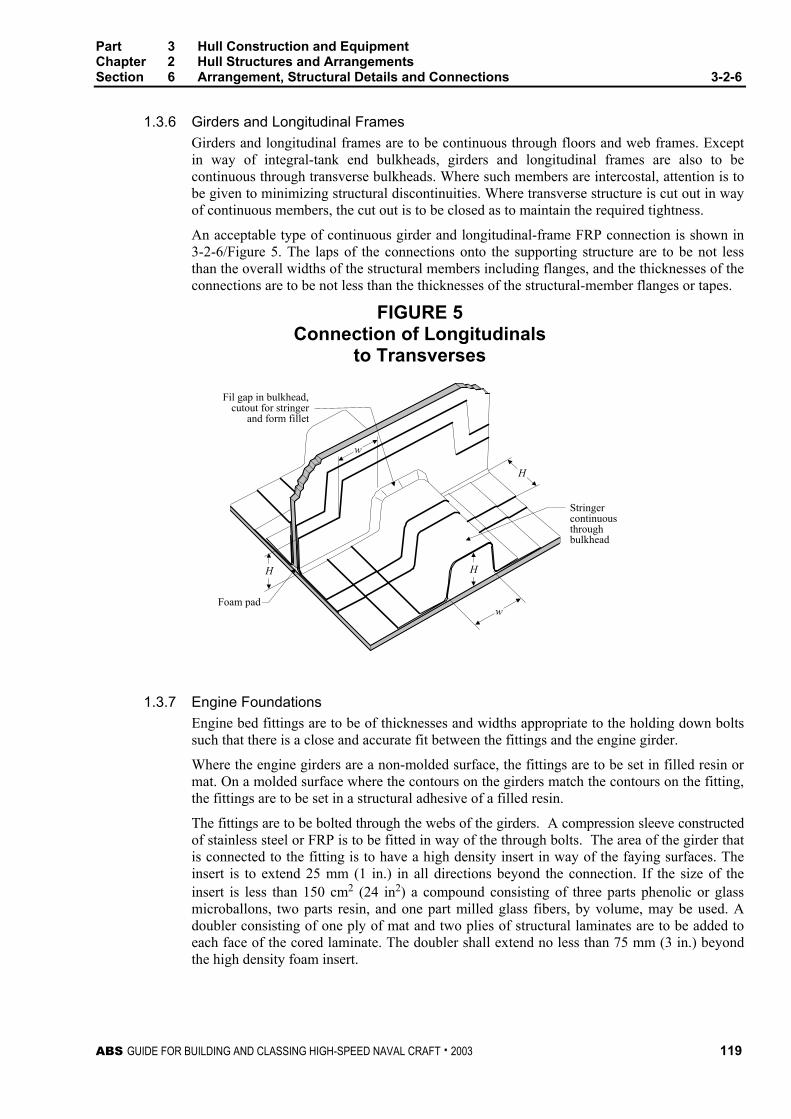
Part 3 Hull Construction and Equipment Chapter 2 Hull Structures and Arrangements Section 6 Arrangement, Structural Details and Connections 3-2-6
ABS GUIDE FOR BUILDING AND CLASSING HIGH-SPEED NAVAL CRAFT . 2003 119
1.3.6 Girders and Longitudinal Frames Girders and longitudinal frames are to be continuous through floors and web frames. Except in way of integral-tank end bulkheads, girders and longitudinal frames are also to be continuous through transverse bulkheads. Where such members are intercostal, attention is to be given to minimizing structural discontinuities. Where transverse structure is cut out in way of continuous members, the cut out is to be closed as to maintain the required tightness.
An acceptable type of continuous girder and longitudinal-frame FRP connection is shown in 3-2-6/Figure 5. The laps of the connections onto the supporting structure are to be not less than the overall widths of the structural members including flanges, and the thicknesses of the connections are to be not less than the thicknesses of the structural-member flanges or tapes.
FIGURE 5 Connection of Longitudinals
to Transverses
H
Foam pad
H
w
Stringercontinuousthroughbulkhead
H
w
Fil gap in bulkhead,cutout for stringer
and form fillet
1.3.7 Engine Foundations Engine bed fittings are to be of thicknesses and widths appropriate to the holding down bolts such that there is a close and accurate fit between the fittings and the engine girder.
Where the engine girders are a non-molded surface, the fittings are to be set in filled resin or mat. On a molded surface where the contours on the girders match the contours on the fitting, the fittings are to be set in a structural adhesive of a filled resin.
The fittings are to be bolted through the webs of the girders. A compression sleeve constructed of stainless steel or FRP is to be fitted in way of the through bolts. The area of the girder that is connected to the fitting is to have a high density insert in way of the faying surfaces. The insert is to extend 25 mm (1 in.) in all directions beyond the connection. If the size of the insert is less than 150 cm2 (24 in2) a compound consisting of three parts phenolic or glass microballons, two parts resin, and one part milled glass fibers, by volume, may be used. A doubler consisting of one ply of mat and two plies of structural laminates are to be added to each face of the cored laminate. The doubler shall extend no less than 75 mm (3 in.) beyond the high density foam insert.

Part 3 Hull Construction and Equipment Chapter 2 Hull Structures and Arrangements Section 6 Arrangement, Structural Details and Connections 3-2-6
120 ABS GUIDE FOR BUILDING AND CLASSING HIGH-SPEED NAVAL CRAFT . 2003
FIGURE 6 Engine Foundations
Engine
Coating or stripinsulator
Engine hold-downbolt
Fiberglass anglepre-molded withtransverse websand chocks
Fiberglassconnecting angles
Shell
Engine
Steel clip in way ofengine hold-down bolts
Fiberglass stiffener withnon-structural core
Engine flange
Shim
Metal angle
Tripping bracket
Metal cap
FRP girder
1.3.8 Deck Fittings Deck fittings, such as cleats and chocks, are to be bedded in sealing compound, structural adhesive, or gasketed, through-bolted, and supported by either oversize washers or metal, plywood or wood backing plates, as shown in 3-2-6/Figure 7. Where washers are used, the laminate in way of the fittings is to be increased at least 25% in thickness. In no case shall the fitting impair the strength or tightness of the structure.

Part 3 Hull Construction and Equipment Chapter 2 Hull Structures and Arrangements Section 6 Arrangement, Structural Details and Connections 3-2-6
ABS GUIDE FOR BUILDING AND CLASSING HIGH-SPEED NAVAL CRAFT . 2003 121
FIGURE 7 Deck Fittings
3T
T
Additional reinforcement
Bonding putty oradhesive
Backing plate
DLockingnuts
High density coreWasher Diameter = 3D
Thickness = D/3
Stainless or solidFRP pipe insert
Core material
Additional reinforcement
Adhesive/sealant
Deck fitting
1.3.9 Through Hull Penetrations Generally all through hull penetrations below the deepest draft design waterline are to be formed by solid FRP laminates, as shown in 3-2-6/Figure 8. When sandwich construction is used for the hull, the core material is to be completely sealed off from the through hull penetration, as shown in 3-2-6/Figure 9. All through hull penetrations are to be taped on both sides of the penetration. The penetration is to be set in a bedding compound.
FIGURE 8 Through Hull Penetration – Solid Laminate
Additionalreinforcement
Adhesive/sealant

Part 3 Hull Construction and Equipment Chapter 2 Hull Structures and Arrangements Section 6 Arrangement, Structural Details and Connections 3-2-6
122 ABS GUIDE FOR BUILDING AND CLASSING HIGH-SPEED NAVAL CRAFT . 2003
FIGURE 9 Through Hull Penetration – Sandwich Laminate
Core beddingmaterial
Washer
Nut - Do notover tighten(to point of
compressingfiberglass)
Adhesive/sealant
High densitycore
Adhesive/sealant
Washer
Nut
Additionalreinforcement
1.3.10 Boundary Angles, Flanges or Tapes 1.3.10(a) FRP to FRP. Secondary bonding of FRP components by means of double boundary angles, flanges or tapes is to be in accordance with Part 2, Chapter 6. Typical boundary angles for FRP components are shown in 3-2-6/Figure 10. At the end connections of sandwich laminates, the core shear strength is to be effectively developed. The bulkheads are to be set into a foam insert, slow curing polyester putty, a microballon mixture or other approved material. The thickness of each boundary angle, flange or tape having similar strength to the members being connected is to be not less than obtained from the following:
1.3.10(b) Single-skin to Single-skin. One-half the thickness of the thinner of the two laminates being joined.
1.3.10(c) Sandwich to Sandwich. The greater of the mean thicknesses of the skins of the sandwich panels being attached.
1.3.10(d) Sandwich to Single Skin. Either one-half the thickness of the single-skin laminate or the mean thickness of the skins of the sandwich panel being attached, whichever is less.
The thickness of each FRP-to-FRP boundary angle also is to be not less than obtained from the following equation:
t = 0.105L + 1.11 mm t = 0.00133L + 0.044 in.
where
L = length, in m (ft), as defined in 3-1-1/3, need not be taken as more than 46.6 m (153 ft).
The width of each flange, not including end taper, is to be not less than 10 times the thickness given above, including the end taper, 13 times the thickness given above, and in general not less than 50 mm (2 in.).

Part 3 Hull Construction and Equipment Chapter 2 Hull Structures and Arrangements Section 6 Arrangement, Structural Details and Connections 3-2-6
ABS GUIDE FOR BUILDING AND CLASSING HIGH-SPEED NAVAL CRAFT . 2003 123
FIGURE 10 Boundary Angles for FRP Components
3 Welded and Mechanical Connections
3.1 Steel and Aluminum
3.1.1 General Components may be fastened by either welding or rivets. For welding, see Section 3-2-13 and Part 2, Chapters 4 and 5.
3.1.2 Expanding Rivets Rivets of the expanding type (blind or “pop” rivets) may be used for lightly loaded connections where lack of accessibility prohibits the use of through fastenings. Such rivets are not to be used for joining components having a total thickness exceeding 12.5 mm (0.50 in.), and are not to be used for joining decks to hulls except as temporary or unstressed fastenings installed for the sake of convenience or speed during assembly.
3.1.3 Conventional Rivets Conventional rivets, where used, are to be subject to special consideration, and are to be of the cold-driven type. Washers, essentially of the same material as the rivets, are to be installed under both the heads and the points.
3.3 Fiber Reinforced Plastic
3.3.1 General Components may be fastened with bolts, machine screws, or self-tapping screws. Where machine screws or self-tapping screws are used, they are not to have countersunk heads. Shanks of all threaded fastenings are to be long enough to pass through the joints, by at least one thread beyond the top of the nut or plastic locking element. Excessive protrusion shall be

Part 3 Hull Construction and Equipment Chapter 2 Hull Structures and Arrangements Section 6 Arrangement, Structural Details and Connections 3-2-6
124 ABS GUIDE FOR BUILDING AND CLASSING HIGH-SPEED NAVAL CRAFT . 2003
avoided, and where the threaded end of the fastener is accessible, and the excess length can constitute a hazard, the excess length is to be removed. Washers are not to be used for the sole purpose of lessening thread protrusion. When it is necessary to reduce the length of thread protrusion, excess length is to be removed without damaging the threads and the bolts dressed to remove rough edges. Where watertight joints are required, suitable sealants or bedding compounds are to be used in addition to the fastenings. All threaded fasteners are to be stainless steel unless alternatives are specifically allowed by the Naval Administration. Sizes and specifications are to be indicated on the submitted plans. The diameter of a fastening is not to be less than the thickness of the thinner component being fastened, with a minimum diameter of 8 mm (0.315 in.). Where hardware is predrilled for fastener sizes that are less than specified above, the size of the fastener used is to match the size of the predrilled holes.
3.3.2 Bolts and Machine Screws Bolts or machine screws are to be used where accessibility permits. The diameter of each fastener is to be at least equal to the thickness of the thinner component being fastened. Bolts and machine screws less than 8 mm (0.315 in.) in diameter are not to be used. Where d is the fastener diameter, fastener centers are to be spaced at a minimum of 3d apart and are to be set in from edges of laminates a minimum of 3d.
Generally in fiber reinforced plastic construction, all bolted connections are to be made through solid fiber reinforced plastic inserts. Where this is not possible, all low density core material is to be replaced with a structurally effective insert. Diameters of fastening holes are not to exceed fastening diameters by more than 0.5 mm (0.02 in.) for bolts less than or equal to 18 mm (0.71 in.) in diameter and 1 mm (0.39 in.) for bolts greater than 18 mm (0.71 in.) in diameter. Elongated and oversize holes are permitted where necessary for adjustment or alignment.
Washers or backing plates are to be installed under all fastening heads and nuts that otherwise would bear on laminates. Washers are to measure not less than 2.25d in outside diameter and 0.1d in thickness. Nuts are to be either of the self-locking type, or other effective means are to be provided to prevent backing off. Mechanical thread locking devices and methods such as lockwashers, either spring, tooth, or tab type, peening wiring, or thread upset after assembly are not to be used.
Bolted connections are, in general, to be bonded along all mating surfaces to insure the tightness of the structure using an accepted structural adhesive, applied in accordance with the manufacturer’s requirements.
In general, all structural, bolted connections are to use threads of bolts in accordance with the requirements in the following table:
Location Pitch (1)
Watertight connections below design waterline 10d Connections in hull above design waterline to deck 15d Hull to deck connections, bonded with approved structural adhesive 15d Connections in deckhouses 20d Deckhouse to deck connection, bonded with approved structural adhesive 15d Minimum distance between reeled lines of bolts 3d
Notes: 1 d is the diameter of the bolt.
2 Internal boundary sealing angle is to be provided for all locations.

Part 3 Hull Construction and Equipment Chapter 2 Hull Structures and Arrangements Section 6 Arrangement, Structural Details and Connections 3-2-6
ABS GUIDE FOR BUILDING AND CLASSING HIGH-SPEED NAVAL CRAFT . 2003 125
All structural, single line, bolted connections without adhesive bonding are to be in accordance with the requirements in the following table:
Location Pitch (1)
Manhole covers to fuel tanks 6d Manhole covers to water tanks 8d Covers to void tanks/cofferdams 10d Bolted access hatches in decks 10d Bolted watertight door frames 8d Window frames 8d
Note: 1 d is the diameter of the bolt.
Bolt holes are to be drilled, without undue pressure at breakthrough, having a diametric tolerance of two percent of the bolt diameter. Where bolted connections are to be made watertight, the hole is to be sealed with resin and allowed to cure before the bolt is inserted. In areas of high stress or where unusual bolting configurations, on the basis of equivalence with the above requirements, are proposed, testing may be required.
3.3.3 Self-tapping Screws In general, no self-tapping screws are to be used in fiber reinforced plastic construction. Self-tapping screws having straight shanks may be used for non-structural connections where lack of accessibility prohibits the use of through fastenings. Where used, self-tapping screws are to have coarse threads.
3.5 Backing Bars and Tapping Plates The requirements for backing plates and bars will be individually considered, on the basis of the loading imposed, details of which are to be indicated on the submitted plans. Metal plates and bars are to be suitably protected against corrosion. Tapping plates may be encapsulated within the laminate, laminated to or bolted to the structure. Tapping plate edges or corners are to be suitably rounded.
5 Deck-to-Hull Joints
5.1 Weather Joints (1 January 2004) The connection is to develop the strength of the deck and shell laminate, whichever is stronger, by either a bolted or bonded connection.
Where flanges are used, the hull flanges are to be equal in thickness and strength to the hull laminates and the deck flanges are to be equal in strength and thickness to the deck laminates. Where bolts are used to develop the required strength of the connection, the faying surfaces are to be set in bedding compound, polyester putty, or other approved material. Minimum widths of overlaps, minimum bolt diameters, and maximum bolt spacing are to be in accordance with 3-2-6/Table 1. Intermediate values may be obtained by interpolation.
FRP bonding angles, where used, are to have flanges of the same strength and of at least one-half the thickness of single skin hull or deck laminate. On sandwich laminates, they are to have the same strength and thickness as the skin of a sandwich laminate, based on the thicker of the two laminates being connected. The widths of the flanges are to be in accordance with the widths of overlaps in 3-2-6/Table 1.
Calculations supporting the geometry of the deck-to-hull joint are to be submitted for craft over 60 m (200 ft) in length.

Part 3 Hull Construction and Equipment Chapter 2 Hull Structures and Arrangements Section 6 Arrangement, Structural Details and Connections 3-2-6
126 ABS GUIDE FOR BUILDING AND CLASSING HIGH-SPEED NAVAL CRAFT . 2003
TABLE 1 Deck-to-Hull Joints (1 January 2004)
SI and MKS Units
Length of Craft L, m
Minimum Widthof Overlap, mm
Minimum Bolt Diameter, mm
Bolt Spacing, mm
9 63.5 6.50 155 12 75.0 7.75 165 15 87.5 9.00 180 18 100.0 10.25 190 21 112.5 11.50 205 24 125.0 12.75 215 27 137.5 14.00 230 30 150.0 15.25 240 33 162.5 16.50 255 36 175.0 17.75 265 39 187.5 19.00 280 42 200.0 20.25 295 45 212.5 21.50 310 48 225.0 22.75 325 51 237.5 23.00 340 54 250.0 24.25 355 57 262.5 25.50 370 60 275.0 26.75 385
US Units
Length of Craft L, ft
Minimum Widthof Overlap, in.
Minimum Bolt Diameter, in.
Bolt Spacing, in.
30 2.5 0.25 6.0
40 3.0 0.30 6.5 50 3.5 0.35 7.0 60 4.0 0.40 7.5 70 4.5 0.45 8.0 80 5.0 0.50 8.5 90 5.5 0.55 9.0 100 6.0 0.60 9.5 110 6.5 0.65 10.0 120 7.0 0.70 10.5 130 7.5 0.75 11.0 140 8.0 0.80 11.5 150 8.5 0.85 12.0 160 9.0 0.90 12.5 170 9.5 0.95 13.0 180 10.0 1.00 13.5 190 10.5 1.05 14.0 200 11.0 1.10 14.5

Part 3 Hull Construction and Equipment Chapter 2 Hull Structures and Arrangements Section 6 Arrangement, Structural Details and Connections 3-2-6
ABS GUIDE FOR BUILDING AND CLASSING HIGH-SPEED NAVAL CRAFT . 2003 127
Each joint is to be protected by a guard, molding, fender, or rail cap of metal, wood, rubber, plastic, or other approved material. The size and ruggedness of this protective strip are to be consistent with the severity of the service for which the craft is intended. The strip is to be installed in such a manner that it may be removed for repair or replacement without endangering the integrity of the deck-to-hull joint.
5.3 Interior Joints Interior decks are to be connected to the hull by shelves, stringers, or other structural members on both sides by FRP tapes. The connection is to effectively develop the strength of the interior deck. The fit-up between the parts are typically not to exceed 5 mm (0.2 in.). The interior deck is to be bedded in syntactic foam or filled resin during assembly and prior to tabbing.
7 Shell Details
7.1 Keels Plate keels are to be not less than shown in 3-2-6/Figure 11a and 3-2-6/Figure 11b, and vertical keels or skegs are to be not less than shown in 3-2-6/Figure 12. Keels or skegs are to be adequate for docking loads, which are to be provided by the designer.
FIGURE 11a Plate Keel in One-piece Hull
t 1.5t ≈3t
B/10
CL
FIGURE 11b Plate Keel in Hull Molded in Halves
Taper 1:24
≈3tB/10 min.
2t
12t
tDoubler
Tapered splice
CL

Part 3 Hull Construction and Equipment Chapter 2 Hull Structures and Arrangements Section 6 Arrangement, Structural Details and Connections 3-2-6
128 ABS GUIDE FOR BUILDING AND CLASSING HIGH-SPEED NAVAL CRAFT . 2003
FIGURE 12 Vertical Keel or Skeg
0.25H
1.5t
≈3tCL
t
H
7.3 Chines and Transoms Chines and transoms are to be not less than shown in 3-2-6/Figures 13a through 13d.
FIGURE 13a Chine or Transom – Single Skin Construction
B/40
1.5t
≈3t
B/40
≈3tt
FIGURE 13b Chine or Transom – Sandwich Construction
Overlap laminates in way of chine forminimum of B/20

Part 3 Hull Construction and Equipment Chapter 2 Hull Structures and Arrangements Section 6 Arrangement, Structural Details and Connections 3-2-6
ABS GUIDE FOR BUILDING AND CLASSING HIGH-SPEED NAVAL CRAFT . 2003 129
FIGURE 13c Stepped Chine – Foam Wedge Option
Core wedge of same densityas topside core
Overlap laminates in way ofchine for minimum of B/20
FIGURE 13d Stepped Chine – Putty Radius
Overlap laminates in way ofchine for minimum of B/20

This Page Intentionally Left Blank
ABS GUIDE FOR BUILDING AND CLASSING HIGH-SPEED NAVAL CRAFT . 2003 131
P A R T
3 C H A P T E R 2 Hull Structures and Arrangements
S E C T I O N 7 Keels, Stems and Shaft Struts
1 Materials
1.1 Ordinary Strength Steels The requirements in the following subsections are based upon ordinary strength steel. For higher strength steels and aluminum alloys see 3-2-7/1.3.
1.3 High Strength Steels and Aluminum Alloys Unless otherwise specified, the required section modulus and inertia for high strength steels and aluminum alloys are as follows:
SM = SMs Q
I = Is Es/Eo
where
SM, I = required section modulus and inertia. Unless specifically stated otherwise, the properties about the minor axis (axis perpendicular to h or w) are to be used.
SMs, Is = Section modulus and inertia obtained from the dimensions given for ordinary strength steel.
Q = as defined in 3-2-1/1.1.1
Es = 2.06 × 10⁵ N/mm2 (21 × 103 kgf/mm2, 30 × 106 psi)
Eo = modulus of the material being considered in N/mm2 (kgf/mm2, psi)
Use of materials other than steel or aluminum will be specially considered.
1.5 Fiber Reinforced Plastic For fiber reinforced plastic hulls, keels and skegs are to have proportions as indicated in 3-2-6/Figure 11 and 3-2-6/Figure 12.

Part 3 Hull Construction and Equipment Chapter 2 Hull Structures and Arrangements Section 7 Keels, Stems and Shaft Struts 3-2-7
132 ABS GUIDE FOR BUILDING AND CLASSING HIGH-SPEED NAVAL CRAFT . 2003
3 Keels
3.1 Bar Keels Where bar keels are fitted the thickness and depth is not to be less than obtained from the following equations:
t = 0.625L + 12.5 mm t = 0.0075L + 0.50 in.
h = 1.46L + 100 mm h = 0.0175L + 4 in.
where
t = thickness, in mm (in.)
h = depth, in mm (in.)
L = length of craft, in m (ft), as defined in Section 3-1-1
Thicknesses and depths other than given above are acceptable provided the section modulii and moments of inertia about the transverse horizontal axis are not less than given above.
3.3 Plate Keels The thickness of the steel plate keel throughout the length of the craft is to be not less than the bottom shell required in Section 3-2-3.
5 Stems
5.1 Bar Stems Where bar stems are fitted the thickness and depth is not to be less than obtained from the following equations:
t = 0.625L + 6.35 mm t = 0.0075L + 0.25 in.
w = 1.25L + 90 mm w = 0.015L + 3.5 in.
where
t = thickness, in mm (in.)
w = width, in mm (in.)
L = length of craft, in m (ft), as defined in Section 3-1-1
This thickness and width is to be maintained between the keel and design load waterline. Above the designed load waterline they may be gradually reduced until the area at the head is 70% of that obtained from the equations.
Thicknesses and widths other than given above are acceptable provided the section modulii and moments of inertia about the longitudinal axis are not less than above. The thickness of the bar stem in general should also not be less than twice the shell thickness.
5.3 Plate Stems Where plate stems are used, they are not to be less in thickness than the bottom shell plating required in 3-2-3/1 and 3-2-3/3, where s is the frame spacing, or 610 mm (24 in.) if greater. Plate stems are to be suitably stiffened.

Part 3 Hull Construction and Equipment Chapter 2 Hull Structures and Arrangements Section 7 Keels, Stems and Shaft Struts 3-2-7
ABS GUIDE FOR BUILDING AND CLASSING HIGH-SPEED NAVAL CRAFT . 2003 133
7 Stern Frames
Craft that are fitted with stern frames, shoe pieces, rudder horns, and rudder gudgeons are to meet the applicable requirements in Section 3-2-13 of the Rules for Building and Classing Steel Vessels.
9 Shaft Struts
9.1 General Tail-shaft (propeller-shaft) struts where provided may be of the V or I type. The following equations are for solid struts having streamline cross-sectional shapes. For struts other than ordinary strength steel see 3-2-7/1. For hollow section and non-streamlined struts, the equivalent cross sectional area, inertia, and section modulus (major axis) are to be maintained. For a streamlined cross-section strut, the inertia about the longitudinal axis is wt3/25 and the section modulus about the same axis is wt2/12.5. Generally each leg of a “V” strut are to have similar cross section. Alternative methods for the determination of “V” strut requirements can be found in Appendix 3-2-A3.
9.3 V Strut
9.3.1 Width The width of each strut arm is not to be less than obtained from the following equation:
w = 2.27d
where
w = width of strut (major axis), in mm (in.)
d = required diameter of ABS Grade 2 tail shaft, in mm (in.). (see Section 4-3-2)
9.3.2 Thickness The thickness of the strut is not to be less than obtained from the following equation:
t = 0.365d
where
t = thickness of strut (minor axis), in mm (in.)
d = required diameter of ABS Grade 2 tail shaft, in mm (in.)
Where the included angle is less than 45 degrees, the foregoing scantlings are to be specially considered.
9.5 I Strut
9.5.1 Width The width of the strut arm is not to be less than obtained from the following equation:
w1 = 3.22d
where
w1 = width of strut (major axis) in mm (in.)
d = diameter of tail shaft in mm (in.)

Part 3 Hull Construction and Equipment Chapter 2 Hull Structures and Arrangements Section 7 Keels, Stems and Shaft Struts 3-2-7
134 ABS GUIDE FOR BUILDING AND CLASSING HIGH-SPEED NAVAL CRAFT . 2003
9.5.2 Thickness The thickness of the strut is not to be less than obtained from the following equation:
t1 = 0.515d
where
t1 = thickness of strut (minor axis), in mm (in.)
d = diameter of tail shaft, in mm (in.)
9.7 Strut Length The length of the longer leg of a V strut or the leg of an I strut, measured from the outside perimeter of the strut barrel or boss to the outside of the shell plating, is not to exceed 10.6 times the diameter of the tail shaft. Where this length is exceeded, the width and thickness of the strut are to be increased, and the strut design will be given special consideration. Where strut length is less than 10.6 times required tailshaft diameter, the section modulus of the strut may be reduced in proportion to the reduced length, provided the section modulus is not less than 0.85 times Guide required section modulus.
9.9 Strut Barrel The thickness of the strut barrel or boss is to be at least one-fifth the diameter of the tail shaft. The length of the strut barrel or boss is to be adequate to accommodate the required length of propeller-end bearings. Strut barrels constructed of aluminum are not subject to the corrections required by 3-2-7/1.3.

ABS GUIDE FOR BUILDING AND CLASSING HIGH-SPEED NAVAL CRAFT . 2003 135
P A R T
3 C H A P T E R 2 Hull Structures and Arrangements
S E C T I O N 8 Rudders
1 General
1.1 Application This Section applies to flat plate and foil profile spade rudders. Rudders having other profiles or with special arrangements for increasing rudder force, such as fins, flaps, steering propellers or other means of steering will be subject to special consideration. Where rudders are fitted on horns or shoepieces, they are to comply with Section 3-2-14 of the Rules for Building and Classing Steel Vessels. The surfaces of rudder stocks in way of exposed bearings are to be of non-corrosive materials. Special consideration will be given to aluminum rudder stocks and fiber reinforced plastic rudders and rudder stocks. Material specifications are to be listed on the plans.
1.3 Rudder and Rudder Stock Materials Rudders, rudder stocks, coupling bolts, and keys are to be made from material in accordance with the requirements of Part 2, Chapter 1. Material tests for coupling bolts and torque transmitting keys need not be witnessed by the Surveyor. The surfaces of rudder stocks in way of exposed bearings are to be of noncorrosive material.
Material factors for castings and forgings used for the stock (Ks), bolts (Kb), and coupling flange (Kf), are to be obtained from the following equation:
K = (ny /Y )e
where
ny = 235 N/mm2 (24 kgf/mm2, 34000 psi)
Y = specified minimum yield strength of the material, in N/mm2 (kgf/mm2, psi), but is not to be taken as greater than 0.7U
U = minimum tensile strength of material used, in N/mm2 (kgf/mm2, psi)
e = 1.0 for Y ≤ 235 N/mm2 (24 kgf/mm2, 34000 psi)
= 0.75 for Y > 235 N/mm2 (24 kgf/mm2, 34000 psi)
1.5 Expected Torque The torque considered necessary to operate the rudder in accordance with 4-3-4/21.7 is to be indicated on the submitted rudder or steering gear plan. See 4-3-4/1.11 and 3-2-8/3.3.3.

Part 3 Hull Construction and Equipment Chapter 2 Hull Structures and Arrangements Section 8 Rudders 3-2-8
136 ABS GUIDE FOR BUILDING AND CLASSING HIGH-SPEED NAVAL CRAFT . 2003
3 Design Loads
3.1 Rudder Force Where the rudder profile can be defined by a single quadrilateral, the rudder force is to be obtained from the following equation. Where the rudder angle φ, exceeds 35°, the rudder force, CR, is to be increased by a factor of 1.74 sin (φ).
CR = nCsKTAV2 kN (tf, Ltf)
where
A = total projected area of rudder, in m2 (ft2)
KT = 1.463 ahead, 1.682 ahead behind fixed propeller nozzle
= 1.063 astern (1.2 for flat sided rudders astern), 1.22 astern behind fixed propeller nozzle (1.38 for flat sided rudders astern behind fixed propeller nozzle)
Cs = speed coefficient.
= 1.0 for Vd < 20 knots
= 3
6046.059.1
−
∆V where Vd ≥ 20 knots, but need not exceed 1.0 and is not to
be taken less than 0.45
V = Vd for the ahead condition but is not to be taken as less than Vmin
= Va for the astern condition but is not to be taken as less than 0.5Vd or 0.5Vmin, whichever is greater
Vd = maximum speed, in knots, with the craft running ahead at the maximum continuous rated shaft rpm
Va = maximum astern speed, in knots
Vmin = (Va + 20)/3
∆ = maximum craft displacement, in metric tons (long tons)
n = 0.132 (0.0135, 0.00123)

Part 3 Hull Construction and Equipment Chapter 2 Hull Structures and Arrangements Section 8 Rudders 3-2-8
ABS GUIDE FOR BUILDING AND CLASSING HIGH-SPEED NAVAL CRAFT . 2003 137
FIGURE 1 Rudder
z
x
Af
3
2
4
1
c
b
x3 + x2 - x1 - x42
z3 + z4 - z2 - z12b=
c=
3.3 Rudder Torque for Scantlings
3.3.1 General The torque to be used for the rudder scantlings is to be as defined in 3-2-8/3.3.2 below.
3.3.2 Rudder Blades The rudder torque for both the ahead and astern conditions is to be determined from the following equation:
QR = CR r kN-m (tf-m, Ltf-ft)
where
CR = rudder force, as calculated in 3-2-8/3.1
r = c(α − Af /A) (but not less than 0.1c for ahead condition
c = mean breadth of rudder area, in m (ft), from 3-2-8/Figure 1
α = 0.33 ahead, 0.66 astern
Af = area of rudder blade situated forward of the centerline of the rudder stock, in m2 (ft2)
A is as defined in 3-2-8/3.1.
3.3.3 Trial Conditions The above values of QR are intended for the design of rudders and should not be directly compared with the torques expected during the trial (see 3-2-8/1.5) or the rated torque of steering gear (see 4-3-4/1.11).

Part 3 Hull Construction and Equipment Chapter 2 Hull Structures and Arrangements Section 8 Rudders 3-2-8
138 ABS GUIDE FOR BUILDING AND CLASSING HIGH-SPEED NAVAL CRAFT . 2003
5 Rudder Stocks
5.1 Upper Rudder Stocks The upper rudder stock is that part of the rudder stock above the neck bearing or above the top pintle. At the upper bearing or tiller, the upper stock diameter is not to be less than obtained from the following equation:
3SRu KQNS = mm (in.)
where
S = upper stock required diameter
Nu = 42.0 (89.9, 2.39)
QR = rudder torque, as defined in 3-2-8/3.3, in kN-m (tf-m, Ltf-m)
Ks = material factor for upper rudder stock, as defined in 3-2-8/1.3
5.3 Lower Rudder Stocks The lower rudder stock diameter is to be determined using the given rudder force and torque in 3-2-8/3. Bending moments, shear forces and reaction forces are to be determined from 3-2-8/5.5 and 3-2-8/9.1.
The lower rudder stock diameter is not to be less than obtained from the following equation:
6 2))(3/4(1 RM/QSS +=l mm (in.)
where
S = upper stock required diameter from 3-2-8/5.1, in mm (in.)
Sl = lower stock required diameter.
M = bending moment at the station of the rudder stock considered, in kN-m (tf-m, Ltf-ft)
QR = rudder torque from 3-2-8/3.3, in kN-m (tf-m, Ltf-ft)
Where the diameter at the neck bearing differs from the diameter of the upper bearing or tiller, a gradual transition is to be provided between the different diameter stocks.
5.5 Bending Moments The bending moment on the rudder and rudder stock may be determined in accordance with Appendix 3-2-A1 or in accordance with the following equations:
Mn = CR ln kN-m (Ltf-ft)
Ms = cR AAC l1 kN-m (Ltf-ft)
where
Mn = bending moment at neck bearing.
Ms = bending moment at section under consideration.
ln = distance from center of neck bearing to the centroid of rudder area, m (ft)

Part 3 Hull Construction and Equipment Chapter 2 Hull Structures and Arrangements Section 8 Rudders 3-2-8
ABS GUIDE FOR BUILDING AND CLASSING HIGH-SPEED NAVAL CRAFT . 2003 139
lc = distance from section under consideration to the centroid of rudder area, A1, m (ft)
A1 = area below section under consideration, m2 (ft2)
CR and A are defined in 3-2-8/3.1.
7 Rudder Couplings
7.1 Flange Couplings Rudder couplings are to be supported by an ample body of metal worked out from the rudder stock. The material outside the bolt holes is not to be less than two thirds the diameter of the bolt. Suitable means of locking the nuts are to be provided. The coupling bolts are to be fitted bolts. The diameter of the bolts and the flange thicknesses are not to be less than obtained from the following equations.
7.1.1 Horizontal Couplings There are to be at least six coupling bolts in horizontal couplings, and the diameter of each bolt is not to be less than obtained by the following equation:
db = 0.62 )/(3sbs nrKKd mm (in.)
where
db = bolt diameter
n = total number of bolts in coupling
r = mean distance, in mm (in.), of the bolt centers from the center of the system of bolts
ds = required diameter of stock in way of coupling, S or Sl from 3-2-8/5.1 or 3-2-8/5.3 as the case may be, in mm (in.)
Kb = material factor for bolts, as defined in 3-2-8/1.3
Ks = material factor for stock, as defined in 3-2-8/1.3
Coupling flange thickness is not to be less than the lesser of the following equations:
tf = db bf /KK mm (in.) tf = 0.9db mm (in.)
where
Kf = material factor for flange, as defined in 3-2-8/1.3
db = required bolt diameter calculated for a number of bolts not exceeding 8
7.1.2 Vertical Couplings There are to be at least eight coupling bolts in vertical couplings and the diameter of each bolt is not to be less than obtained from the following equation:
db = 0.81ds )/( sb nKK mm (in.)
where
n = total number of bolts
ds, Kb, Ks are as defined above.
Part 3 Hull Construction and Equipment Chapter 2 Hull Structures and Arrangements Section 8 Rudders 3-2-8
140 ABS GUIDE FOR BUILDING AND CLASSING HIGH-SPEED NAVAL CRAFT . 2003
In addition, the first moment of area of the bolts about the center of the coupling is not to be less than given by the following equation:
m = 0.00043ds3 mm3 (in3)
where
m = first moment of area
ds = diameter as defined in 3-2-8/7.1.1
Coupling flange thickness is not to be less than db.
7.3 Tapered Stock Couplings
7.3.1 Taper Ratio Tapered stocks secured to the rudder casting by a nut on the end of the stock are to have a length of taper in the casting generally not less than 1.5 times the diameter of the stock at the top of the rudder. Couplings without hydraulic arrangements for mounting and dismounting the coupling are to have a taper on diameter of 1/8 to 1/12. For couplings with hydraulic arrangements for mounting and dismounting the coupling (mounting with oil injection and hydraulic nut) the taper on the diameter is to be 1/12 to 1/20, and the push-up oil pressure and the push up length will be specially considered upon submission of calculations in each case.
7.3.2 Keying Where the stock is keyed to the rudder casting, torsional strength equivalent to that of the required upper stock diameter is to be provided. The top of the keyway is to be located well below the top of the rudder. For higher strength materials, shear and bearing areas of keys and keyways are to be based on the lesser strength properties of the key and the materials in which keyways are cut, as appropriate.
7.3.3 Locking Nut The nut is to be proportioned in accordance with the following and is to be fitted with an effective locking device. (See 3-2-8/Figure 2).
External thread diameter dg ≥ 0.65 do
Length of nut hn ≥ 0.6 dg
Outer diameter of nut dn ≥ 1.2du or 1.5dg, whichever is greater
7.5 Keyless Couplings Hydraulic and shrink fit keyless couplings will be specially considered upon submittal of detailed preloading and stress calculations and fitting instructions. The calculated torsional holding capacity is to be at least 2.0 times the transmitted torque based on the steering gear relief valve setting. Preload stress is not to exceed 70% of the minimum yield strength of the rudder stock housing or the rudder stock materials.
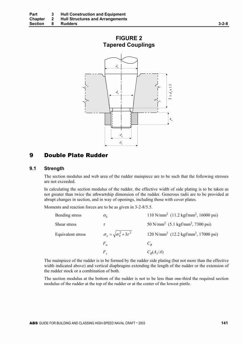
Part 3 Hull Construction and Equipment Chapter 2 Hull Structures and Arrangements Section 8 Rudders 3-2-8
ABS GUIDE FOR BUILDING AND CLASSING HIGH-SPEED NAVAL CRAFT . 2003 141
FIGURE 2 Tapered Couplings
do
du
dg
dn
hn
l ≥ d
o x
1.5
9 Double Plate Rudder
9.1 Strength The section modulus and web area of the rudder mainpiece are to be such that the following stresses are not exceeded.
In calculating the section modulus of the rudder, the effective width of side plating is to be taken as not greater than twice the athwartship dimension of the rudder. Generous radii are to be provided at abrupt changes in section, and in way of openings, including those with cover plates.
Moments and reaction forces are to be as given in 3-2-8/5.5.
Bending stress σb 110 N/mm2 (11.2 kgf/mm2, 16000 psi)
Shear stress τ 50 N/mm2 (5.1 kgf/mm2, 7300 psi)
Equivalent stress 22 3τσσ += be 120 N/mm2 (12.2 kgf/mm2, 17000 psi)
Fn CR
Fs CR(A1/A)
The mainpiece of the rudder is to be formed by the rudder side plating (but not more than the effective width indicated above) and vertical diaphragms extending the length of the rudder or the extension of the rudder stock or a combination of both.
The section modulus at the bottom of the rudder is not to be less than one-third the required section modulus of the rudder at the top of the rudder or at the center of the lowest pintle.

Part 3 Hull Construction and Equipment Chapter 2 Hull Structures and Arrangements Section 8 Rudders 3-2-8
142 ABS GUIDE FOR BUILDING AND CLASSING HIGH-SPEED NAVAL CRAFT . 2003
9.3 Rudder Plating
9.3.1 Side, Top and Bottom Plating The plating thickness is not to be less than obtained from the following equation:
t = 0.0055sβ ( )ACkdk R /21 + × Q + k3 mm (in.)
where
k1 = 1.0 (1.0, 0.305)
k2 = 0.1 (0.981, 10.7)
k3 = 2.5 (2.5, 0.1)
d = summer loadline draft of the craft, in m (ft)
CR = rudder force according to 3-2-8/3, in kN (tf, Ltf)
A = rudder area, in m2 (ft2)
s = smaller unsupported dimension of plating, in mm (in.)
b = greater unsupported dimension of plating, in mm (in.)
β = 2)/(5.01.1 bs− ; maximum 1.0 for b/s ≥ 2.5
Q = material factor for rudder plating, as defined in 3-2-1/1.1.1
The thickness of the rudder side or bottom plating is to be at least 2 mm (0.08 in.) greater than that required by 3-2-3/1.3 with p obtained from 3-2-2/9.1, for which h is measured from the lower edge of the plate to the design load waterline in displacement mode.
9.3.2 Diaphragm Plates Vertical and horizontal diaphragms are to be fitted within the rudder, effectively attached to each other and to the side plating. Vertical diaphragms are to be spaced approximately 1.5 times the spacing of horizontal diaphragms. Openings are in general not to be more than 0.5 times the depth of the web.
The thickness of diaphragm plates is not to be less than 70% of the required rudder side plate thickness or 8 mm (0.31 in.) whichever is greater. Welding is to be in accordance with Sections 2-4-1 and 3-2-13. Where inaccessible for welding inside the rudder, it is recommended that diaphragms be fitted with flat bars and the side plating be connected to these flat bars by continuous welds or by 75 mm (3 in.) slot welds spaced at 150 mm (6 in.) centers. The slots are to be fillet welded around the edge, and filled with a suitable compound.
9.3.3 Watertightness The rudder is to be watertight and is to be tested in accordance with 6-1-1/Table 1.
11 Single Plate Rudders
11.1 Mainpiece Diameter The mainpiece diameter is calculated according to 3-2-8/5.3. The lower third may be tapered down to 0.75 times stock diameter at the bottom of the rudder.

Part 3 Hull Construction and Equipment Chapter 2 Hull Structures and Arrangements Section 8 Rudders 3-2-8
ABS GUIDE FOR BUILDING AND CLASSING HIGH-SPEED NAVAL CRAFT . 2003 143
11.3 Blade Thickness The blade thickness is not to be less than obtained from the following equation:
tb = 0.0015sV + 2.5 mm tb = 0.0015sV + 0.1 in.
where
s = spacing of stiffening arms, in mm (in.), not to exceed 1000 mm (39 in.)
V = speed, as defined in 3-2-8/3.1
11.5 Arms The thickness of the arms is not to be less than the blade thickness obtained in 3-2-8/11.3. The section modulus of each set of arms about the axis of the rudder stock is not to be less than obtained from the following equation:
SM = 0.0005 sC12V2 cm3 SM = 0.0000719 sC1
2V2 in3
where
C1 = horizontal distance from the aft edge of the rudder to the centerline of the rudder stock, in m (ft)
s, V are defined in 3-2-8/11.3.
13 Shelled Rudder Blades
Rudder blades that are constructed out of cast resilient polymers or filled FRP shells are to have a solid metallic core that complies with the requirements for single plate rudders, see 3-2-8/11.
15 Rudder Stops
Strong and effective rudder stops are to be fitted. Where adequate positive stops are provided within the gear, structural stops will not be required. See also Section 4-3-4.
17 Supporting and Anti-Lifting Arrangements
17.1 Rudder Stock Bearings
17.1.1 Bearing Surfaces The bearing surface Ab for rudder stocks, shafts and pintles is not to be less than obtained from the following equation:
Ab = 1000 P/qa mm2 Ab = 2240 P/qa in2
where
Ab = projected area of bearing surface = dl lb where dl is the outer diameter of the liner and lb is the bearing length not to be taken greater than 1.2dl
P = bearing reaction force, in kN (tf, Ltf). See 3-2-A1/3.7
qa = allowable surface pressure, as indicated in 3-2-8/Table 2, depending on bearing material, in N/mm2 (kgf/mm2, psi)

Part 3 Hull Construction and Equipment Chapter 2 Hull Structures and Arrangements Section 8 Rudders 3-2-8
144 ABS GUIDE FOR BUILDING AND CLASSING HIGH-SPEED NAVAL CRAFT . 2003
TABLE 1 Bearing Pressure
qa†
Bearing Material N/mm2 qa† kgf/mm2 psi
lignum vitae 2.5 0.25 360 white metal, oil lubricated 4.5 0.46 650 Synthetic material with hardness between 60 and 70 Shore D* 5.5 0.56 800 Steel§, bronze and hot-pressed bronze-graphite materals 7.0 0.71 1000
† Higher values than given in the table may be taken if they are verified by tests.
§ Stainless and wear-resistant steel in an approved combination with stock liner.
* Indentation hardness test at 23°C and with 50% moisture, according to a recognized standard. Synthetic bearing materials to be of approved type.
17.1.2 Bearing Clearance With metal bearings clearance is not to be less than db/1000 + 1.0 mm, (db/1000 + 0.04 in.) on the diameter. If non-metallic bearing material is applied, the bearing clearance is to be specially determined considering the material’s swelling and thermal expansion properties. This clearance is in no case to be less than 1.5 mm (0.06 in.) on diameter or the bushing manufacturer’s recommended clearance.
For spade rudders with a rudder stock diameter of 400 mm (15.75 in.) or less, the clearances on the diameter are not to be less than given below:
Stock Diameter, mm (in.) Metallic Bushing, mm (in.) Synthetic Bushing (1), mm (in.)
400 (15.75) 1.15 (0.045) 1.15 (0.045) + E (2) 300 (11.81) 0.85 (0.033) 0.85 (0.033) + E 200 (7.87) 0.78 (0.031) 0.78 (0.031) + E 100 (3.94) 0.75 (0.030) 0.75 (0.030) + E
Notes 1 The bushing manufacturer’s recommended running clearance may be used as an alternative to
these clearances.
2 E = expansion allowance provided by bushing manufacturer, mm (in.).
17.3 Rudder Carrier and Anti Lifting Devices Effective means are to be provided for supporting the weight of the rudder assembly. At least half of the rudder carrier holding-down bolts are to be fitted bolts. Alternatively, other effective means of preventing horizontal movement of the rudder may be specially considered. Means are also to be provided to prevent accidental unshipping, lifting or undue movement of the rudder which may cause damage to the steering gear. See Appendix 3-2-A1 for guidance.

ABS GUIDE FOR BUILDING AND CLASSING HIGH-SPEED NAVAL CRAFT . 2003 145
P A R T
3 C H A P T E R 2 Hull Structures and Arrangements
S E C T I O N 9 Protection of Deck Openings
1 General
All openings in decks are to be framed to provide efficient support and attachment for the ends of the deck beams. The proposed arrangement and details for all hatchways are to be submitted for approval.
3 Position of Deck Openings
For the purpose of this Guide, two positions of deck openings are defined as follows:
Position 1 Upon exposed main and raised quarter decks, and upon exposed superstructure decks situated forward of a point located a quarter of the craft length from the forward perpendicular.
Position 2 Upon exposed superstructure decks situated abaft a quarter of the craft length from the forward perpendicular.
5 Hatchway Coamings, Companionway Sills and Access Sills
5.1 Coaming and Sill Heights The heights above deck of the coamings, the sills of companionways and access openings, are to be not less than given in 3-2-9/Table 1. Where the coaming or sill height will interfere with the mission of the craft, as indicated by the Naval Administration, a lesser sill height will be considered. Where hatch covers are substantially constructed and made tight by means of gaskets and clamping devices, these heights may be reduced, or the coamings omitted entirely, provided that the safety of the craft is not thereby impaired in any sea conditions. Sealing arrangements are to be weathertight if coaming is fitted, and watertight for flush covers.
TABLE 1 Coamings and Sill Heights
L equal to or over 24 meters (79 feet) in length Position 1 Position 2
Hatch Coamings 600 mm (23.5 in.) 450 mm (17.5 in.) Companionway Sills 600 mm (23.5 in.) 380 mm (15 in.)
Access Sills 380 mm (15 in.) 380 mm (15 in.)

Part 3 Hull Construction and Equipment Chapter 2 Hull Structures and Arrangements Section 9 Protection of Deck Openings 3-2-9
146 ABS GUIDE FOR BUILDING AND CLASSING HIGH-SPEED NAVAL CRAFT . 2003
TABLE 1 (continued) Coamings and Sill Heights
L under 24 meters (79 feet) in length Position 1 Position 2
Hatch Coamings and Companionways 450 mm (17.5 in.) 300 mm (12 in.)
Access Sills 380 mm (15 in.) 300 mm (12 in.)
Note: For craft with L < 24 m, the coaming/sill height should be as indicated above, unless otherwise specifically requested by the Naval Administration.
7 Enclosed Superstructures
To be considered enclosed, superstructures are to meet the following requirements. Superstructures with openings which do not fully comply with these requirements are to be considered as open superstructures. See also 3-2-11/3.7.
7.1 Closing Appliances All openings in the bulkheads of enclosed superstructures are to be provided with efficient means of closing, so that in any sea conditions water will not penetrate the craft. Opening and closing appliances are to be framed and stiffened so that the whole structure, when closed, is equivalent to the unpierced bulkhead.
Doors for access openings into enclosed superstructures are to be of steel or other approved material, permanently and strongly attached to the bulkhead. The doors are to be provided with gaskets and clamping devices, or other equivalent arrangements, permanently attached to the bulkhead or to the doors themselves, and the doors are to be so arranged that they can be operated from both sides of the bulkhead. The construction of the doors is to be as required in 3-2-5/1.13.
Portlights and windows in the end bulkheads of enclosed superstructures are to be of substantial construction and provided with efficient inside deadlights, as required in 3-2-11/5.
The location and means of the closing appliances for windows are to be in accordance with 3-2-11/7.
7.3 Sills of Access Openings Except as otherwise provided in this Guide, the height of the sills of access openings in bulkheads at the ends of enclosed superstructures is to be at least 380 mm (15 in.) above the deck. See 3-2-9/Table 1 for required sill heights.
7.5 Means of Access Superstructures are not to be regarded as enclosed unless access is provided for the crew to reach machinery and other working spaces inside these superstructures by alternate means which are available at all times when bulkhead openings are closed.

Part 3 Hull Construction and Equipment Chapter 2 Hull Structures and Arrangements Section 9 Protection of Deck Openings 3-2-9
ABS GUIDE FOR BUILDING AND CLASSING HIGH-SPEED NAVAL CRAFT . 2003 147
9 Hatchways Closed by Covers of Steel and Fitted with Gaskets and Clamping Devices
9.1 Strength of Covers The maximum allowable stress and deflection under design load, w, and the minimum top plate thickness are as follows:
Maximum allowable stress 0.235σu
Maximum allowable deflection 0.0028s
Top plate thickness 0.01s, but not less than 6.0 mm (0.24 in.)
Position 1
w = 0.097L + 7.45 kN/m2
w = 0.0099L + 0.76 tf/m2
w = 0.61L + 158.0 lbf/ft2
Position 2
w = 0.0709L + 5.65 kN/m2
w = 0.00725L + 0.576 tf/m2
w = 0.450L + 118.5 lbf/ft2
where
w = design load, in kN/m2 (tf/m2, lbf/ft2)
L = length of craft, in m (ft), as defined in Section 3-1-1, but is not to be taken less than 24 m (79 ft).
s = stiffener spacing, in mm (in.)
σu = minimum ultimate tensile strength, in N/mm2 (kgf/mm2, psi)
9.3 Means for Securing Weathertightness The means for securing and maintaining weathertightness is to be such that the tightness can be maintained in any sea condition. The covers are to be hose tested in position under a water pressure of at least 2.1 bar (2.1 kgf/cm2, 30 psi) at the time of installation.
9.5 Flush Hatch Covers Where flush hatch covers are fitted on the freeboard deck within the forward one-fourth length, and the craft is operating with low freeboard (e.g., assigned a freeboard less than Type-B under the International Convention on Load Lines 1966), the assumed loads on flush hatch covers are to be increased 15% over that indicated in 3-2-9/9.1.
Part 3 Hull Construction and Equipment Chapter 2 Hull Structures and Arrangements Section 9 Protection of Deck Openings 3-2-9
148 ABS GUIDE FOR BUILDING AND CLASSING HIGH-SPEED NAVAL CRAFT . 2003
11 Hatchways Closed by Portable Covers in Lower Decks or within Fully Enclosed Superstructures
11.1 General The following scantlings are intended for conventional type covers. Those for covers of special types are to be specially considered.
11.3 Steel Covers The thickness of the plating for steel covers is not to be less than required for lower decks as obtained from 3-2-3/1. A stiffening bar is to be fitted around the edges as required to provide the necessary rigidity to permit the covers being handled without deformation. The effective depth of the framework is normally to be not less than 4% of its unsupported length. The stiffeners, in association with the plating to which they are attached, are to have section modulus, SM, as determined by the following equation:
SM = 7.8hsl2 cm3 SM = 0.0041hsl2 in3
where
h = tween-deck height, in m (ft)
s = spacing of the stiffeners, in m (ft)
l = length of the stiffener, in m (ft)
11.5 Wheel Loading Where provision is to be made for the operation and stowage of vehicles having rubber tires, the thickness of the hatch cover plating is to be in accordance with 3-2-3/1.3.4.
13 Hatchways Closed by Covers of Materials Other Than Steel
Hatch covers constructed of materials other than steel will be specially considered.
14 Small Hatches on the Exposed Fore Deck (1 January 2004)
14.1 Application This subsection is applicable to craft with length L (as defined in 3-1-1/3) not less than 80 meters (263 feet).
The requirements of this subsection apply to all small hatches [opening normally 2.5 square meters (27 ft2) or less] located on the exposed fore deck within the forward 0.25L, where the deck in way of the hatch is less than 0.1L or 22 m (72.2 ft) above the summer load line, whichever is less.
Hatches designed for emergency escape need not comply with 3-2-9/14.5i), 3-2-9/14.5ii), the third paragraph of 3-2-9/14.7 and 3-2-9/14.9.

Part 3 Hull Construction and Equipment Chapter 2 Hull Structures and Arrangements Section 9 Protection of Deck Openings 3-2-9
ABS GUIDE FOR BUILDING AND CLASSING HIGH-SPEED NAVAL CRAFT . 2003 149
14.3 Strength For small rectangular steel hatch covers, the plate thickness, stiffener arrangement and scantlings are to be in accordance with 3-2-9/Table 2 and 3-2-9/Figure 1. Stiffeners, where fitted, are to be aligned with the metal-to-metal contact points required in 3-2-9/14.7. See also 3-2-9/Figure 1. Primary stiffeners are to be continuous. All stiffeners are to be welded to the inner edge stiffener, see 3-2-9/Figure 2.
The upper edge of the hatchway coaming is to be suitably reinforced by a horizontal section, normally not more than 170 to 190 mm (6.9 to 7.5 in.) from the upper edge of the coaming.
For small hatch covers of circular or similar shape, the cover plate thickness and reinforcement is to provide strength and stiffness equivalent to the requirements for small rectangular hatches.
For small hatch covers constructed of materials other than steel, the required scantlings are to provide strength and stiffness equivalent to 235 N/mm2 (24 kgf/mm2, 34 psi) yield strength steel.
14.5 Primary Securing Devices The primary securing devices are to be such that their hatch covers can be secured in place and made weather-tight by means of a mechanism employing any one of the following methods:
i) Butterfly nuts tightening onto forks (clamps), or
ii) Quick acting cleats, or
iii) A central locking device.
Dogs (twist tightening handles) with wedges are not acceptable.
14.7 Requirements for Primary Securing The hatch cover is to be fitted with a gasket of elastic material. This is to be designed to allow a metal-to-metal contact at a designed compression and to prevent over compression of the gasket by green sea forces that may cause the securing devices to be loosened or dislodged. The metal-to-metal contacts are to be arranged close to each securing device in accordance with 3-2-9/Figure 1, and of sufficient capacity to withstand the bearing force.
The primary securing method is to be designed and manufactured such that the designed compression pressure is achieved by one person without the need of any tools.
For a primary securing method using butterfly nuts, the forks (clamps) are to be of robust design. They are to be designed to minimize the risk of butterfly nuts being dislodged while in use; by means of curving the forks upward and a raised surface on the free end, or a similar method. The plate thickness of unstiffened steel forks is not to be less than 16 mm. An example arrangement is shown in 3-2-9/Figure 2.
For small hatch covers located on the exposed deck forward of the fore-most cargo hatch, the hinges are to be fitted such that the predominant direction of green sea will cause the cover to close, which means that the hinges are normally to be located on the fore edge.
On small hatches located between the main hatches, for example between Nos. 1 and 2, the hinges are to be placed on the fore edge or outboard edge, whichever is practicable for protection from green water in beam sea and bow quartering conditions.
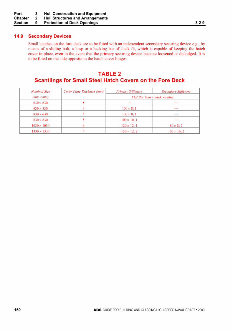
Part 3 Hull Construction and Equipment Chapter 2 Hull Structures and Arrangements Section 9 Protection of Deck Openings 3-2-9
150 ABS GUIDE FOR BUILDING AND CLASSING HIGH-SPEED NAVAL CRAFT . 2003
14.9 Secondary Devices Small hatches on the fore deck are to be fitted with an independent secondary securing device e.g., by means of a sliding bolt, a hasp or a backing bar of slack fit, which is capable of keeping the hatch cover in place, even in the event that the primary securing device became loosened or dislodged. It is to be fitted on the side opposite to the hatch cover hinges.
TABLE 2 Scantlings for Small Steel Hatch Covers on the Fore Deck
Primary Stiffeners Secondary Stiffeners Nominal Size (mm × mm)
Cover Plate Thickness (mm) Flat Bar (mm × mm); number
630 × 630 8 --- ---
630 × 830 8 100 × 8; 1 ---
830 × 630 8 100 × 8; 1 ---
830 × 830 8 100 × 10; 1 ---
1030 × 1030 8 120 × 12; 1 80 × 8; 2 1330 × 1330 8 150 × 12; 2 100 × 10; 2

Part 3 Hull Construction and Equipment Chapter 2 Hull Structures and Arrangements Section 9 Protection of Deck Openings 3-2-9
ABS GUIDE FOR BUILDING AND CLASSING HIGH-SPEED NAVAL CRAFT . 2003 151
FIGURE 1 Arrangement of Stiffeners
Nominal size 630 × 630 Nominal size 630 × 830
Nominal size 830 × 830 Nominal size 830 × 630
Nominal size 1030 × 1030 Nominal size 1330 × 1330
Hinge
Securing device/metal to metal contact
Primary stiffener
Secondary stiffener

Part 3 Hull Construction and Equipment Chapter 2 Hull Structures and Arrangements Section 9 Protection of Deck Openings 3-2-9
152 ABS GUIDE FOR BUILDING AND CLASSING HIGH-SPEED NAVAL CRAFT . 2003
FIGURE 2 Example of Primary Securing Method
M20
1
5 (min. 16 mm)
6
29
3
4
φ20
11
810
7
1: butterfly nut2: bolt3: pin4: center of pin5: fork (clamp) plate6: hatch cover7: gasket8: hatch coaming9: bearing pad welded on the bracket of a toggle bolt for metal to metal contact10: stiffener11: inner edge stiffener
(Note: Dimensions in millimeters)
15 Hatchways within Open Superstructures
Hatchways within open superstructures are to be considered as exposed.
17 Hatchways within Deckhouses
Hatchways within deckhouses are to have coamings and closing arrangements as required in relation to the protection afforded by the deckhouse from the standpoint of its construction and the means provided for the closing of all openings into the house.

Part 3 Hull Construction and Equipment Chapter 2 Hull Structures and Arrangements Section 9 Protection of Deck Openings 3-2-9
ABS GUIDE FOR BUILDING AND CLASSING HIGH-SPEED NAVAL CRAFT . 2003 153
19 Machinery Casings
19.1 Arrangement Machinery-space openings in Position 1 or 2 are to be framed and efficiently enclosed by casings of ample strength, and wherever practicable, those in main decks are to be within superstructures or deckhouses. Casings are to be of material similar to that of the surrounding structure. Openings in exposed casings are to be fitted with doors complying with the requirements of 3-2-9/7.1; the sills are to be in accordance with 3-2-9/5.1 for companionways. Other openings in such casings are to be fitted with equivalent covers, permanently attached. Stiffeners are to be spaced at not more than 760 mm (30 in.)
19.3 Scantlings The scantlings of exposed casings are to be similar to those obtained for superstructures and deckhouses in accordance with the applicable requirements of Sections 3-2-2, 3-2-3 and 3-2-4.
The scantlings of casings within enclosed superstructures or deckhouses will be specially considered.
21 Miscellaneous Openings in Freeboard and Superstructure Decks
21.1 Manholes and Scuttles Manholes and flush scuttles in Position 1 or 2 within superstructures other than enclosed superstructures are to be closed by substantial covers capable of being made watertight. Unless secured by closely spaced bolts, the covers are to be permanently attached.
21.3 Other Openings Openings in freeboard decks other than hatchways, machinery-space openings, manholes and flush scuttles are to be protected by an enclosed superstructure, or by a deckhouse or companionway of equivalent strength and weathertightness. Any such opening in an exposed superstructure deck or in the top of a deckhouse on the main deck which gives access to a space below the main deck or a space within an enclosed superstructure is to be protected by an efficient deckhouse or companionway. Doorways in such deckhouses or companionways are to be fitted with doors complying with the requirements given in 3-2-9/7.1.
21.5 Escape Openings The closing appliances of escape openings are to be readily operable from each side.
21.7 Chain Pipe Opening (1 January 2004) For craft with length L (as defined in 3-1-1/3) greater than 24 meters (79 feet), chain pipes through which anchor cables are led are to be provided with permanently attached closing appliances to minimize ingress of water. A canvas cover with appropriate lashing arrangement will be acceptable for this purpose. Cement and wire mesh arrangement is not permitted.
The arrangement on craft that are not subject to the International Convention on Load Lines or its Protocol may be specially considered.

This Page Intentionally Left Blank

ABS GUIDE FOR BUILDING AND CLASSING HIGH-SPEED NAVAL CRAFT . 2003 155
P A R T
3 C H A P T E R 2 Hull Structures and Arrangements
S E C T I O N 10 Protection of Shell Openings
1 Cargo, Gangway, or Fueling Ports
1.1 Construction Cargo, gangway, or fueling ports in the sides of craft are to be strongly constructed and capable of being made thoroughly watertight. Where frames are cut in way of such ports, web frames are to be fitted on the sides of the openings, and suitable arrangements are to be provided for the support of the beams over the openings. Thick shell plates or doublers are to be fitted as required to compensate for the openings. The corners of the openings are to be well rounded. Waterway angles and scuppers are to be provided on the decks in way of ports in cargo spaces below the freeboard deck or in cargo spaces within enclosed superstructures to prevent the spread of any leakage water over the decks.
Indicators showing whether the ports in the side shell below the freeboard or superstructure deck are secured closed or open are to be provided on the navigation bridge.
1.3 Location The lower edges of cargo, gangway, or fueling-port openings are not to be below a line parallel to the main deck at side having as its lowest point the designed load waterline or upper edge of the uppermost load line.
3 Bow Doors, Inner Doors, Side Shell Doors and Stern Doors
3.1 General Where steel bow doors of the visor or side-opening type are fitted leading to complete or long forward enclosed superstructure, bow doors and inner doors are to meet the requirements of this section. Hull supporting structure in way of the bow doors is to be able to withstand the loads imposed by the bow doors securing and supporting devices without exceeding the allowable stresses for those devices, both given in this section. Special consideration will be given to bow doors constructed of materials other than steel.
3.3 Arrangement
3.3.1 General As far as practicable, bow doors and inner doors are to be arranged so as to preclude the possibility of the bow door causing structural damage to the inner door or to the collision bulkhead in the case of damage to or detachment of the bow door.

Part 3 Hull Construction and Equipment Chapter 2 Hull Structures and Arrangements Section 10 Protection of Shell Openings 3-2-10
156 ABS GUIDE FOR BUILDING AND CLASSING HIGH-SPEED NAVAL CRAFT . 2003
3.3.2 Bow Doors Bow doors are to be situated above the main deck except that where a watertight recess fitted for arrangement of ramps or other related mechanical devices is located forward of the collision bulkhead and above the deepest waterline, the bow doors may be situated above the recess.
3.3.3 Inner Doors An inner door is to be fitted in the extension of the collision bulkhead required by 3-2-5/1.3.1. A vehicle ramp made watertight and conforming to 3-2-5/1.3.1 in the closed position may be accepted for this purpose.
3.3.4 Side Shell and Stern Doors Stern doors for passenger craft are to be situated above the freeboard deck. Stern doors for ro-ro cargo craft and all side shell doors need not be situated above the freeboard deck.
5 Securing, Locking and Supporting of Doors
5.1 Definitions
5.1.1 Securing Device A device used to keep the door closed by preventing it from rotating about its hinges or its pivoted attachments to the craft.
5.1.2 Supporting Device A device used to transmit external or internal loads from the door to a securing device and from the securing device to the craft’s structure, or a device other than a securing device, such as a hinge, stopper or other fixed device, that transmits loads from the door to the craft’s structure.
5.1.3 Locking Device A device that locks a securing device in the closed position.
7 Securing and Supporting Devices
7.1 General Securing and supporting devices are to be arranged in accordance with this subsection, and are to have scantlings as required by 3-2-10/13.9, 3-2-10/15.5 or 3-2-10/17.9, as appropriate.
7.3 Bow Doors Means are to be provided to prevent lateral or vertical movement of the bow doors when closed. Means are also to be provided for mechanically fixing the door in the open position.
Means of securing and supporting the door are to maintain equivalent strength and stiffness of the adjacent structure.
7.3.1 Clearance and Packing The maximum design clearance between the door and securing/supporting devices is not to exceed 3 mm (0.12 in.). Where packing is fitted, it is to be of a comparatively soft type and the supporting forces are to be carried by the steel structure only.
Part 3 Hull Construction and Equipment Chapter 2 Hull Structures and Arrangements Section 10 Protection of Shell Openings 3-2-10
ABS GUIDE FOR BUILDING AND CLASSING HIGH-SPEED NAVAL CRAFT . 2003 157
7.3.2 Visor Door Arrangement. The pivot arrangement is to be such that the visor is self closing under external loads. The closing moment, My, as defined in 3-2-10/19.5.1 is not to be less than Myo as given by the following equation:
Myo = Wc + 0.1 22 ba + 22zx FF +
where W, a, b, c, Fx and Fz are as defined in 3-2-10/19.
In addition, the arrangement of the door is to be such that the reaction forces of pin or wedge supports at the base of the door does not act in the forward direction when the door is loaded in accordance with 3-2-10/19.5.4.
7.5 Side Shell and Stern Doors
Means are to be provided to prevent lateral or vertical movement of the side shell or stern doors when closed. Means are also to be provided for mechanically fixing the doors in the open position.
The means of securing and supporting the doors are to have strength and stiffness equivalent to the adjacent structure.
Clearance and packing for side shell and stern doors are to be in accordance with 3-2-10/7.3.1.
9 Securing and Locking Arrangement
9.1 General Securing devices are to be provided with a mechanical locking arrangement (self locking or separate arrangement), or are to be of the gravity type.
9.3 Operation Securing devices are to be simple to operate and readily accessible. The opening and closing systems as well as the securing and locking devices are to be interlocked in such a way that they can only operate in the proper sequence.
9.3.1 Hydraulic Securing Devices Where hydraulic securing devices are applied, the system is to be mechanically lockable in the closed position. In the event of a loss of hydraulic fluid, the securing devices are to remain locked.
The hydraulic system for securing and locking devices is to be isolated from other hydraulic circuits when in the closed position.
9.3.2 Remote Control Where bow doors and inner doors give access to a vehicle deck, an arrangement for remote control from a position above the freeboard deck is to be provided allowing closing and opening of the doors and associated securing and locking of the securing and locking devices for every door. The operating panels for operation of doors are to be accessible to authorized persons only. A notice plate giving instructions to the effect that all securing devices are to be closed and locked before leaving harbor is to be placed at each operating panel and is to be supplemented by warning indicator lights as indicated in 3-2-10/9.5.1.

Part 3 Hull Construction and Equipment Chapter 2 Hull Structures and Arrangements Section 10 Protection of Shell Openings 3-2-10
158 ABS GUIDE FOR BUILDING AND CLASSING HIGH-SPEED NAVAL CRAFT . 2003
9.5 Indication/Monitoring
9.5.1 Indicators The indicator system is to be designed on the fail safe principle and in accordance with the following:
9.5.1(a) Location and Type. Separate indicator lights are to be provided on the navigation bridge to show that the bow door and inner door are closed and that their locking devices are properly positioned.
The indication panel on the navigation bridge is to be equipped with a mode selection function “harbor/sea voyage”, arranged so that an audible and visible alarm is given if in the sea voyage condition, the bow door or inner door is not closed, or any of the securing devices is not in the correct position.
Indication of the open/closed position of every door and every securing and locking device is to be provided at the operating panels.
9.5.1(b) Indicator lights. Indicator lights are to be designed so that they cannot be manually turned off. The indication panel is to be provided with a lamp test function.
9.5.1(c) Power Supply. The power supply for the indicator system is to be independent of the power supply for operating and closing the doors.
9.5.1(c) Protection of Sensors. Sensors are to be protected from water, ice formation and mechanical damage.
9.5.2 Water Leakage Protection A drainage system is to be arranged in the area between the bow door and ramp and in the area between the ramp and inner door where fitted. The system is to be equipped with an audible alarm function to the navigation bridge for water level in these areas exceeding 0.5 m (1.6 ft) above the car deck level.
A water leakage detection system with audible alarm and television surveillance are to be arranged to provide an indication to the navigation bridge and to the engine control room of leakage through the inner door.
9.5.3 Door Surveillance Between the bow door and the inner door a television surveillance system is to be fitted with a monitor on the navigation bridge and in the engine control room. The system is to monitor the position of doors and a sufficient number of their securing devices.
11 Tightness
11.1 Bow Doors Bow doors are to be so fitted as to ensure tightness consistent with operational conditions and to give effective protection to the inner doors.
11.3 Inner Doors Inner doors forming part of the extension of the collision bulkhead are to be weathertight over the full height of the cargo space and arranged with fixed sealing supports on the aft side of the doors.
11.5 Side Shell and Stern Doors
Side shell doors and stern doors are to be so fitted as to ensure watertightness.

Part 3 Hull Construction and Equipment Chapter 2 Hull Structures and Arrangements Section 10 Protection of Shell Openings 3-2-10
ABS GUIDE FOR BUILDING AND CLASSING HIGH-SPEED NAVAL CRAFT . 2003 159
13 Bow Door Scantlings
13.1 General Bow doors are to be framed and stiffened so that the whole structure is equivalent to the unpierced bulkhead when closed.
13.3 Primary Structure Scantlings of primary members are to be designed so that the allowable stresses indicated in 3-2-10/25.1 are not exceeded when the structure is subjected to the design loads indicated in 3-2-10/19.1. Unless the ends of the primary members are effectively fixed-ended, the member is to be considered simply supported.
13.5 Secondary Stiffeners Secondary stiffeners are to be supported by primary members constituting the main stiffening of the door. The section modulus, SM, of secondary stiffeners is to be as required by 3-2-4/1.3. In addition, stiffener webs are to have a net sectional area not less than that obtained from the following equation:
A = VQ/10 cm2 (A = VQ cm2, A = VQ/6.5 in2)
where
V = shear force, in kN (tf, Ltf), in the stiffener calculated using the uniformly distributed external pressure Peb given in 3-2-10/19.1
Q = as defined in 3-2-1/1.1.1
13.7 Plating The thickness of bow door plating is to be not less than that required for side shell plating at the same location.
13.9 Securing and Supporting Devices Scantlings of securing and supporting devices are to be designed so that the allowable stresses indicated in 3-2-10/25.1 are not exceeded when the structure is subjected to the design loads indicated in 3-2-10/19.3. All load transmitting elements in the design load path from the door through securing and supporting devices into the craft structure, including welded connections, are to meet the strength standards required for securing and supporting devices. Where fitted, threaded bolts are not to carry support forces, and the maximum tensile stress in way of the threads is not to exceed the allowable stress given in 3-2-10/25.5.
In determining the required scantlings, the door is to be assumed to be a rigid body. Only those active supporting and securing devices having an effective stiffness in the relevant direction are to be included and considered when calculating the reaction forces on the devices. Small or flexible devices such as cleats intended to provide load compression of the packing material are not to be included in the calculations.
13.9.1 Bearing Pressure The bearing pressure on steel to steel bearings is to be calculated by dividing the design force by the projected bearing area, and is not to exceed the allowable stress given in 3-2-10/25.3.

Part 3 Hull Construction and Equipment Chapter 2 Hull Structures and Arrangements Section 10 Protection of Shell Openings 3-2-10
160 ABS GUIDE FOR BUILDING AND CLASSING HIGH-SPEED NAVAL CRAFT . 2003
13.9.2 Redundancy In addition to the above requirements, the arrangement of the securing and supporting devices is to be designed with redundancy such that in the event of failure of any single securing or supporting device, the stresses in the remaining devices do not exceed the allowable stresses indicated in 3-2-10/25.1 by more than 20% under the above loads.
13.9.3 Visor Door Securing and Supporting Devices Securing and supporting devices, excluding the hinges, are to be capable of resisting the vertical design force given in 3-2-10/19.5.3 without stresses exceeding the allowable stresses in 3-2-10/25.1.
Two securing devices are to be provided at the lower part of the door, each capable of providing the full reaction force required to prevent opening of the door without stresses exceeding the allowable stresses indicated in 3-2-10/25.1. The opening moment, Mo, to be balanced by this force is as given in 3-2-10/19.5.2.
13.9.4 Side-opening Door Thrust Bearing A thrust bearing is to be provided in way of girder ends at the closing of the two doors, and is to prevent one door from shifting towards the other one under the effect of unsymmetrical pressure. Securing devices are to be fitted to secure sections thrust bearing to one another.
13.11 Visor Door Lifting Arms and Supports Where visor type bow doors are fitted, calculations are to be submitted verifying that lifting arms and their connections to the door and craft structure are adequate to withstand the static and dynamic forces applied during the lifting and lowering operations under a wind pressure of at least 1.5 kN/m2
(0.15 tf/m2, 0.014 Ltf/ft2)
15 Inner Door Scantlings
15.1 General Scantlings of inner doors are to meet the requirements of this Subsection. In addition, where inner doors are used as vehicle ramps, scantlings are not to be less than required for vehicle decks.
15.3 Primary Structure Scantlings of primary members are to be designed so that the allowable stresses indicated in 3-2-10/25.1 are not exceeded when the structure is subjected to the design loads indicated in 3-2-10/21.1.
15.5 Securing and Supporting Devices Scantlings of securing and supporting devices are to be designed so that the allowable stresses indicated in 3-2-10/25.1 are not exceeded when the structure is subjected to the design loads indicated in 3-2-10/21. Where fitted, threaded bolts are not to carry support forces, and the maximum tensile stress in way of the threads is not to exceed the allowable stress given in 3-2-10/25.5.
The bearing pressure on steel to steel bearings is to be calculated by dividing the design force by the projected bearing area, and is not to exceed the allowable stress given in 3-2-10/25.3.

Part 3 Hull Construction and Equipment Chapter 2 Hull Structures and Arrangements Section 10 Protection of Shell Openings 3-2-10
ABS GUIDE FOR BUILDING AND CLASSING HIGH-SPEED NAVAL CRAFT . 2003 161
17 Side Shell Door and Stern Door Scantlings
17.1 General
Scantlings of side shell doors or stern doors are to meet the requirements of this subsection. The doors are to be framed and stiffened so that the whole structure is equivalent to the intact side or stern structure when closed. In addition, where the doors are used as vehicle ramps, scantlings are not to be less than required for vehicle decks in Sections 3-2-3 and 3-2-4.
17.3 Primary Structure
Scantlings of primary members are to be designed so that the allowable stresses indicated in 3-2-16/25.1 are not exceeded when the structure is subjected to the design loads indicated in 3-2-16/23. The primary members are to be considered simply supported at their support points unless the end connections are effectively restrained.
17.5 Secondary Stiffeners
Secondary stiffeners are to be supported by primary members constituting the main stiffening of the door. The section modulus, SM, of secondary stiffeners is to be not less than required by Section 3-2-4 for frames in the same location. In addition, the net sectional area of stiffener webs is to be in accordance with 3-2-10/13.5, using the external pressure, pe, given in 3-2-10/23.
17.7 Plating
The thickness of side or stern door plating is to be not less than that required for side shell plating at the same location.
17.9 Securing and Supporting Devices
Scantlings of securing and supporting devices are to be designed so that the allowable stresses indicated in 3-2-10/25.1 are not exceeded when the structure is subjected to the design loads indicated in 3-2-10/23. All load-transmitting elements in the design load path from the door through securing and supporting devices into the craft structure, including welded connections, are to meet the strength standards required for securing and supporting devices. Where fitted, threaded bolts are not to carry support forces, and the maximum tensile stress in way of the threads is not to exceed the allowable stress given in 3-2-10/25.5.
In determining the required scantlings, the door is to be assumed to be a rigid body. Only those active supporting and securing devices having an effective stiffness in the relevant direction are to be included and considered when calculating the reaction forces on the devices. Small or flexible devices such as cleats intended to provide compression load on the packing material are not to be included in the calculations.
17.9.1 Bearing Pressure
The bearing pressure on steel to steel bearings is to be calculated by dividing the design force by the projected bearing area, and is not to exceed the allowable stress given in 3-2-10/25.3.
17.9.2 Redundancy
In addition to the above requirements, the arrangement of the securing and supporting devices is to be designed with redundancy such that in the event of a failure of any single securing or supporting device, the stresses in the remaining devices do not exceed the allowable stresses indicated in 3-2-10/25.1 by more than 20% under the above loads.

Part 3 Hull Construction and Equipment Chapter 2 Hull Structures and Arrangements Section 10 Protection of Shell Openings 3-2-10
162 ABS GUIDE FOR BUILDING AND CLASSING HIGH-SPEED NAVAL CRAFT . 2003
19 Bow Door Design Loads
19.1 External Pressure The design external pressure, Peb, is to be taken as indicated by the following equation.
Peb = nc (0.22 + 0.15 tan β ) (0.4Vd sin α + 0.6 1kL )2 kN/m2 ( tf/m2, Ltf/ft2)
where
n = 2.75 (0.280, 0.0256)
c = 0.0125L for craft having L < 80 m (260 ft)
= 1.0 for other craft
L = length of craft as defined in 3-1-1/3, in m (ft)
β = flare angle at the point to be considered, defined as the angle between a vertical line and the tangent to the side shell plating measured in a vertical plane normal to the horizontal tangent to the shell plating. See 3-2-10/Figure 1.
α = entry angle at the point to be considered, defined as the angle between a longitudinal line parallel to the centerline and the tangent to the shell plating in a horizontal plane. See 3-2-10/Figure 1.
k = 1.0 (1.0, 0.305)
Vd = craft design speed as defined in 3-2-8/3.1
FIGURE 1 Entry and Flare Angles
Section A - A
Section B - B
A A
B
B
ß
α

Part 3 Hull Construction and Equipment Chapter 2 Hull Structures and Arrangements Section 10 Protection of Shell Openings 3-2-10
ABS GUIDE FOR BUILDING AND CLASSING HIGH-SPEED NAVAL CRAFT . 2003 163
19.3 External Forces The design external forces considered in determining scantlings of securing and supporting devices of bow doors are not to be taken less than those given by the following equations:
Fx = PemAx
Fy = PemAy
Fz = PemAz
where
Fx = the design external force in the longitudinal direction, in kN (tf, Ltf)
Fy = the design external force in the horizontal direction, in kN (tf, Ltf)
Fz = the design external force in the vertical direction, in kN (tf, Ltf)
Ax = area, in m2 (ft2), of the transverse vertical projection of the door between the levels of the bottom of the door and the upper deck or between the bottom of the door and the top of the door, whichever is less.
Ay = area, in m2 (ft2), of the longitudinal vertical projection of the door between the levels of the bottom of the door and the upper deck or between the bottom of the door and the top of the door, whichever is less.
Az = area, in m2 (ft2), of the horizontal projection of the door between the levels of the bottom of the door and the upper deck or between the bottom of the door and the top of the door, whichever is less.
Pem = bow door pressure, Peb, determined using αm and βm in place of α and β.
βm = flare angle measured at a point on the bow door l/2 aft of the stem line on a plane h/2 above the bottom of the door, as shown in 3-2-10/Figure 2.
αm = entry angle measured at the same point as βm. See 3-2-10/Figure 2.
h = height, in m (ft), of the door between the levels of the bottom of the door and the upper deck or between the bottom of the door and the top of the door, whichever is less.
l = length, in m (ft), of the door at a height of h/2 above the bottom of the door.
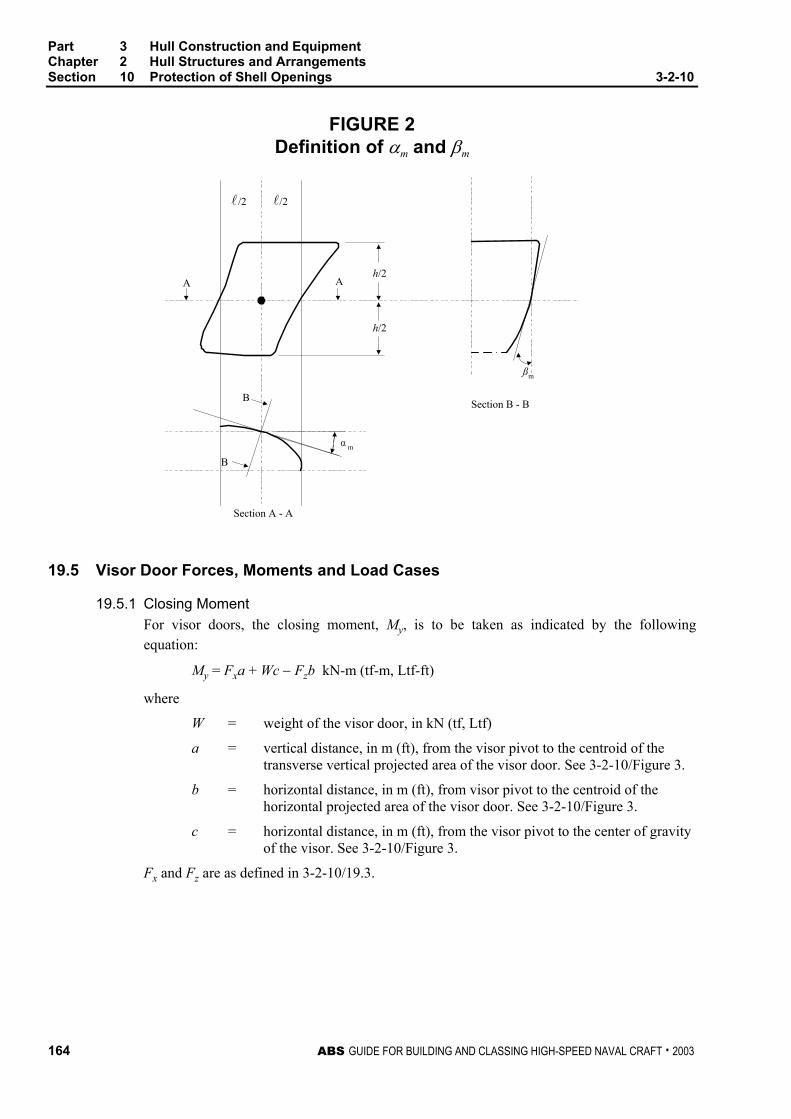
Part 3 Hull Construction and Equipment Chapter 2 Hull Structures and Arrangements Section 10 Protection of Shell Openings 3-2-10
164 ABS GUIDE FOR BUILDING AND CLASSING HIGH-SPEED NAVAL CRAFT . 2003
FIGURE 2 Definition of αm and βm
AA
Section B - B
Section A - A
B
B
α m
ßm
/2 /2
h/2
h/2
l l
19.5 Visor Door Forces, Moments and Load Cases
19.5.1 Closing Moment For visor doors, the closing moment, My, is to be taken as indicated by the following equation:
My = Fxa + Wc − Fzb kN-m (tf-m, Ltf-ft)
where
W = weight of the visor door, in kN (tf, Ltf)
a = vertical distance, in m (ft), from the visor pivot to the centroid of the transverse vertical projected area of the visor door. See 3-2-10/Figure 3.
b = horizontal distance, in m (ft), from visor pivot to the centroid of the horizontal projected area of the visor door. See 3-2-10/Figure 3.
c = horizontal distance, in m (ft), from the visor pivot to the center of gravity of the visor. See 3-2-10/Figure 3.
Fx and Fz are as defined in 3-2-10/19.3.

Part 3 Hull Construction and Equipment Chapter 2 Hull Structures and Arrangements Section 10 Protection of Shell Openings 3-2-10
ABS GUIDE FOR BUILDING AND CLASSING HIGH-SPEED NAVAL CRAFT . 2003 165
FIGURE 3 Visor Type Bow Door
Elevation Front View
Plan View
AxAy
Z
Az
XCL
LC
W d
b
c
a
CG
19.5.2 Opening Moment The opening moment, Mo, is to be taken as indicated by the following equation:
Mo = Wd + 5Axa kN-m (Wd + 0.5Axa tf-m, Wd + 0.047Axa Ltf-ft)
where
d = vertical distance, in m (ft), from the hinge axis to the center of gravity of the door.
W, Ax and a are as indicated above.
19.5.3 Vertical Design Force The vertical design force is to be taken as Fz – W, where Fz is as defined in 3-2-10/19.3 and W is as defined in 3-2-10/19.5.1.
19.5.4 Combined Load Case 1 The visor doors are to be evaluated under a load of Fx, Fz and W acting simultaneously with Fx and Fz acting at the centroid of their respective projected areas.

Part 3 Hull Construction and Equipment Chapter 2 Hull Structures and Arrangements Section 10 Protection of Shell Openings 3-2-10
166 ABS GUIDE FOR BUILDING AND CLASSING HIGH-SPEED NAVAL CRAFT . 2003
19.5.5 Combined Load Case 2 The visor doors are to be evaluated under a load of 0.7Fy acting on each side separately together with 0.7Fx, 0.7Fz and W. Fx, Fy and Fz are to be taken as acting at the centroid of their respective projected areas.
19.7 Side-Opening Door Load Cases
19.7.1 Combined Load Case 1 Side opening doors are to be evaluated under a load of Fx, Fy, Fz and W acting simultaneously with Fx, Fy and Fz acting at the centroid of their respective projected areas.
19.7.2 Combined Load Case 2 Side opening doors are to be evaluated under a load of 0.7Fx, 0.7Fz and W acting on both doors simultaneously and 0.7Fy acting on each door separately.
21 Inner Door Design Loads
21.1 External Pressure The design external pressure is to be taken as the greater of Pei or Ph as given by the following equations:
Pei = 0.45L1 kN/m2 (0.046L1 tf/m2 , 0.00128L1 Ltf/ft2)
Ph = 10h kN/m2 (1.0h tf/m2, 0.029h Ltf/ft2 )
where
L1 = as defined in 3-1-1/3.
h = the distance, in m (ft), from the load point to the top of the cargo space.
21.3 Internal Pressure The design internal pressure, Pi, is to be taken as not less than 25 kN/m2 (2.5 tf/m2, 0.23 Ltf/ft2).
23 Side Shell and Stern Doors
23.1 Design Forces for Primary Members
The design force, in kN (tf, Ltf), for primary members is to be the greater of the following:
External force: Fe = A pe
Internal force: Fi = Fo + W
23.3 Design Forces for Securing or Supporting Devices of Doors Opening Inwards The design force, in kN (tf, Ltf), for securing or supporting devices of doors opening inwards is to be the greater of the following:
External force: Fe = A pe + Fp
Internal force: Fi = Fo + W
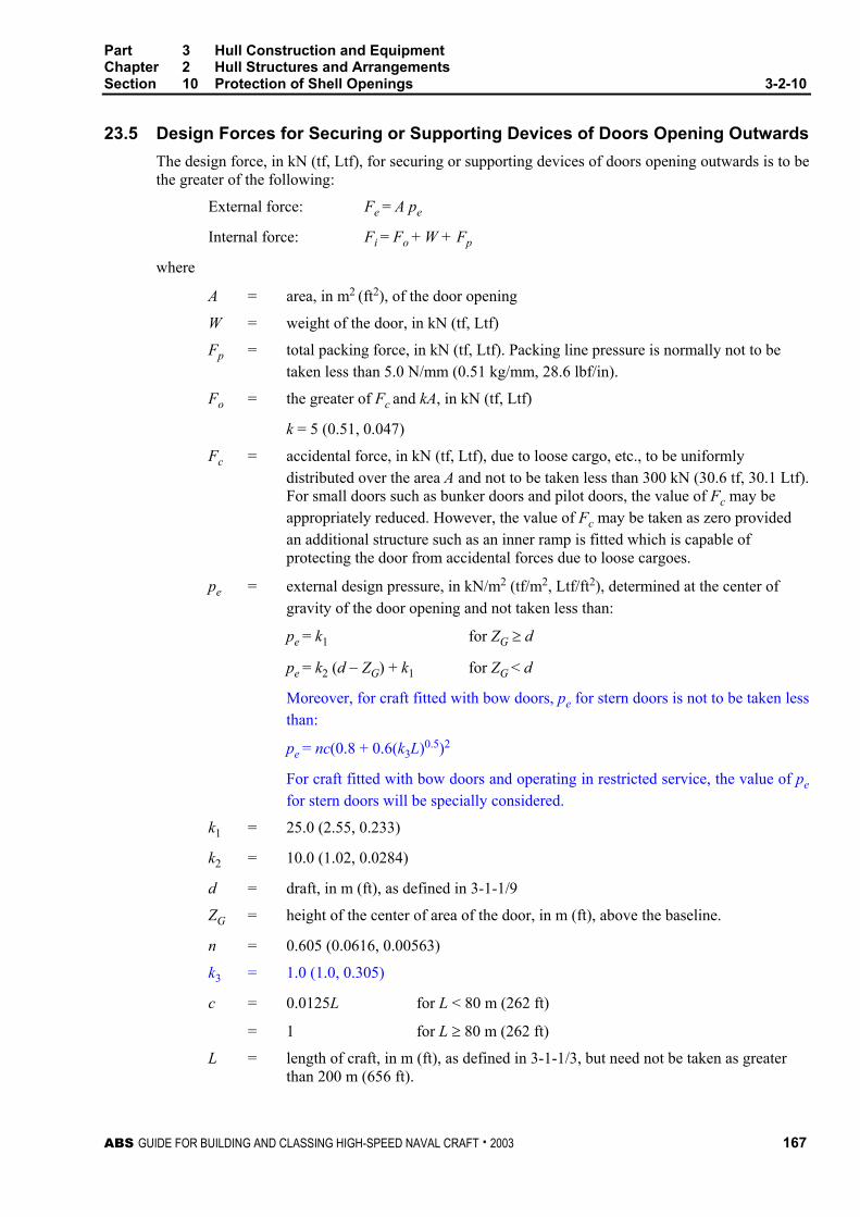
Part 3 Hull Construction and Equipment Chapter 2 Hull Structures and Arrangements Section 10 Protection of Shell Openings 3-2-10
ABS GUIDE FOR BUILDING AND CLASSING HIGH-SPEED NAVAL CRAFT . 2003 167
23.5 Design Forces for Securing or Supporting Devices of Doors Opening Outwards The design force, in kN (tf, Ltf), for securing or supporting devices of doors opening outwards is to be the greater of the following:
External force: Fe = A pe
Internal force: Fi = Fo + W + Fp
where
A = area, in m2 (ft2), of the door opening
W = weight of the door, in kN (tf, Ltf)
Fp = total packing force, in kN (tf, Ltf). Packing line pressure is normally not to be taken less than 5.0 N/mm (0.51 kg/mm, 28.6 lbf/in).
Fo = the greater of Fc and kA, in kN (tf, Ltf)
k = 5 (0.51, 0.047)
Fc = accidental force, in kN (tf, Ltf), due to loose cargo, etc., to be uniformly distributed over the area A and not to be taken less than 300 kN (30.6 tf, 30.1 Ltf). For small doors such as bunker doors and pilot doors, the value of Fc may be appropriately reduced. However, the value of Fc may be taken as zero provided an additional structure such as an inner ramp is fitted which is capable of protecting the door from accidental forces due to loose cargoes.
pe = external design pressure, in kN/m2 (tf/m2, Ltf/ft2), determined at the center of gravity of the door opening and not taken less than:
pe = k1 for ZG ≥ d
pe = k2 (d − ZG) + k1 for ZG < d
Moreover, for craft fitted with bow doors, pe for stern doors is not to be taken less than:
pe = nc(0.8 + 0.6(k3L)0.5)2
For craft fitted with bow doors and operating in restricted service, the value of pe for stern doors will be specially considered.
k1 = 25.0 (2.55, 0.233)
k2 = 10.0 (1.02, 0.0284)
d = draft, in m (ft), as defined in 3-1-1/9
ZG = height of the center of area of the door, in m (ft), above the baseline.
n = 0.605 (0.0616, 0.00563)
k3 = 1.0 (1.0, 0.305)
c = 0.0125L for L < 80 m (262 ft)
= 1 for L ≥ 80 m (262 ft)
L = length of craft, in m (ft), as defined in 3-1-1/3, but need not be taken as greater than 200 m (656 ft).

Part 3 Hull Construction and Equipment Chapter 2 Hull Structures and Arrangements Section 10 Protection of Shell Openings 3-2-10
168 ABS GUIDE FOR BUILDING AND CLASSING HIGH-SPEED NAVAL CRAFT . 2003
25 Allowable Stresses
25.1 Primary Structure and Securing and Supporting Devices The following stresses are not to be exceeded under the loads indicated above:
Shear Stress: τ = 80/Q N/mm2 ( 8.2/Q kgf/mm2, 11600/Q psi)
Bending Stress: σ = 120/Q N/mm2 (12.2/Q kgf/mm2, 17400/Q psi)
Equivalent Stress: ( 22 3τσ + ): σe = 150/Q N/mm2 (15.3/Q kgf/mm2, 21770/Q psi)
where Q is defined in 3-2-1/1.1.1.
25.3 Steel Securing and Supporting Devices Bearing Stress For steel to steel bearings in securing and supporting devices, the nominal bearing pressure is not to exceed 0.8σf, where σf is the yield stress of the bearing material.
25.5 Tensile Stress on Threaded Bolts The tensile stress in threaded bolts is not to exceed 125/Q N/mm2 (12.7/Q kgf/mm2, 18,000/Q psi).
27 Operating and Maintenance Manual
The following information is to be submitted for review:
27.1 Manual An operating and maintenance manual for the bow door and inner door is to be provided on board and is to contain at least the following:
• Main particulars and design drawings
• Service conditions (e.g., service area)
• Restrictions, acceptable clearances for supports
• Maintenance and function testing
• Register of inspections and repairs
27.3 Operating Procedures Documented operating procedures for closing and securing the bow door and inner door are to be kept on board and posted at an appropriate location.

ABS GUIDE FOR BUILDING AND CLASSING HIGH-SPEED NAVAL CRAFT . 2003 169
P A R T
3 C H A P T E R 2 Hull Structures and Arrangements
S E C T I O N 11 Bulwarks, Rails, Ports, Portlights, Windows, Ventilators, Tank Vents and Overflows
1 Bulwarks and Guard Rails
Bulwarks or guard rails or a combination of both, are in general to be provided on exposed decks, and on exposed tops of superstructures and deckhouses. Additional bulwark and guardrail requirements may be specified by the Naval Administration due to specific military mission requirements.
1.1 Location and Heights Bulwarks or guardrails are also to be provided on the exposed side of any platform surface that is greater than 600 mm (24 in.) or higher above the adjacent surface. The height of bulwarks and guard rails on exposed freeboard and superstructure decks is to be at least 1 m (39.5 in.). Where this height would interfere with the normal service or operation of a craft, a lesser height may be approved if adequate protection is provided. Where approval of a lesser height is requested, justifying information is to be submitted, such as arrangements provided to prevent personnel going over the guard rails or bulwarks. In exposed areas not traversed in the normal operation of the craft, where it is not practical to fit bulwarks or guard rails, hand or grab rails may be considered.
1.3 Strength of Bulwarks Bulwarks are to be of ample strength for their height and location, suitably stiffened at the top, and if necessary at the bottom, and supported by efficient stays or brackets. Stays or brackets on the main weather deck are to be spaced not more than 1.83 m (6.0 ft). Openings in bulwarks are to be smooth-edged, with well-rounded corners.
1.5 Arrangements of Guard Rails
1.5.1 Fixed, removable or hinged stanchions are to be fitted at approximately 1.5 m (5 ft) apart.
1.5.2 At least every third stanchion is to be supported by a bracket or stay.

Part 3 Hull Construction and Equipment Chapter 2 Hull Structures and Arrangements Section 11 Bulwarks, Rails, Ports, Portlights, Windows, Ventilators, Tank Vents and
Overflows 3-2-11
170 ABS GUIDE FOR BUILDING AND CLASSING HIGH-SPEED NAVAL CRAFT . 2003
1.5.3 The opening below the lowest course is not to exceed 230 mm (9 in.) The distance between the remaining courses is not to be more than 380 mm (15 in.)
1.5.4 For craft with rounded gunwales, stanchions are to be placed on the flat of the deck.
1.5.5 Portable stanchions are to be retained with stainless steel toggle pins. The toggle pins are to be provided with stainless steel wire rope attached to the portable stanchion to prevent the loss of the pin.
1.5.6 The imposed loads from safety harness, or other rescue equipment connecting points that are located on the guardrails are to be considered.
1.7 Life Lines Life lines, where fitted, are to be a minimum of 9.5 mm (0.375 in.) in diameter, 7 × 19 construction, and made of stainless steel wire rope. They are to have a stainless steel turnbuckle at one end and a stainless steel screw pin shackle at the other.
3 Freeing Ports
3.1 Basic Area Where bulwarks on freeboard decks form wells, ample provision is to be made for rapidly freeing the decks of water and for draining them. The minimum freeing-port area on each side of the craft for each well 20 m (66 ft.) or less in length is to be obtained from the following equation:
A = 0.7 + 0.035l m2 A = 7.6 + 0.115l ft2
Where the bulwark length exceeds 20 m (66 ft):
A = 0.07l m2 A = 0.23l ft2
where
A = freeing-port, area in m2 (ft2)
l = bulwark length, in m (ft), but need not exceed 0.7L.
The minimum area for each well on superstructure decks is to be one half of the area obtained from the above equations.
If a bulwark is more than 1.2 m (3.9 ft) in height, the freeing-port area is to be increased by 0.004 m2
per meter (0.04 ft2 per foot) of length of well for each 0.1 m (1 ft) difference in height. If a bulwark is less than 0.9 m (3 ft) in height, the freeing-port area may be decreased by the same ratio. A freeing port area less than required by the equations above may be accepted providing that the reduced area is specifically requested by the Naval Administration.
3.3 Trunks, Deckhouses and Hatchway Coamings Where a craft is fitted with a trunk on the freeboard deck, and open rails are not fitted in way of the trunk for at least one-half its length, or where continuous or substantially continuous hatchway side coamings are fitted or long deckhouse exist between detached superstructures, the minimum area of freeing-port openings is to be obtained from the following table:

Part 3 Hull Construction and Equipment Chapter 2 Hull Structures and Arrangements Section 11 Bulwarks, Rails, Ports, Portlights, Windows, Ventilators, Tank Vents and
Overflows 3-2-11
ABS GUIDE FOR BUILDING AND CLASSING HIGH-SPEED NAVAL CRAFT . 2003 171
Breadth of Trunk, Deckhouse or Hatchway in Relation to Breadth of Craft
Area of Freeing Ports in Relation to Total Area of Bulwarks
40% or less 75% or more
20% 10%
The area of freeing ports at intermediate breadths is to be obtained by linear interpolation.
3.5 Superstructure Decks Where bulwarks on superstructure decks form wells, the bulwarks are to comply with 3-2-11/3.1 except that the minimum freeing-port area on each side of the craft for each well is to be one-half of the area obtained in 3-2-11/3.1 and 3-2-11/3.3.
3.7 Open Superstructures In craft having superstructures that are open at either end or both ends, adequate provisions for freeing the spaces within such superstructures are to be provided; the arrangements will be subject to special approval.
3.9 Details of Freeing Ports The lower edges of the freeing ports are to be as near the deck as practicable. Two-thirds of the required freeing-port area is to be provided in the half of the well nearest the lowest point of the sheer curve. Freeing-port openings are to be protected by rails or bars in such a manner that the maximum clear vertical or horizontal space is 230 mm (9 in.). Where shutters are fitted, ample clearance is to be provided to prevent them from jamming. Hinges are to have pins and bearings of corrosion resistant material and in general, the hinges are to be located at the top of the shutter. If the shutters are equipped with securing appliances, the appliances are to be of approved construction.
5 Portlights
5.1 Construction Portlights fitted below the main weather deck or in superstructure and house side plating are to be of substantial construction and provided with steel, aluminum or other approved material inside deadlights, permanently attached and arranged to be capable of being closed and secured watertight. Except in way of the machinery space, portlights may be of the hinged opening type, with hinge pins of non-corrosive material. Where craft are subject to damaged stability requirements of 3-3-1/3.3, portlights found to be situated below a final damage equilibrium waterline are to be of the non opening type. Portlight frames are to be of steel or other approved material and are to be attached to the hull by through bolts or equivalent. Lower edges of portlights are not to be below a line parallel to the main weather deck at side having its lowest point at a distance above the design waterline either 2.5% of the craft breadth or 500 mm (19.5 in.) whichever is greater.
When specifically requested by the Naval Administration, consideration will be given to the omission of deadlights depending on the type and thickness of the portlight.
The thickness of portlights of tempered or toughened monolithic safety glass is to be not less than given in 3-2-11/Table 1. Consideration will also be given to laminated glass, acrylic and polycarbonate glazing materials based upon equivalent flexural strength and stiffness. See 3-2-11/Table 3 for glazing mechanical properties.
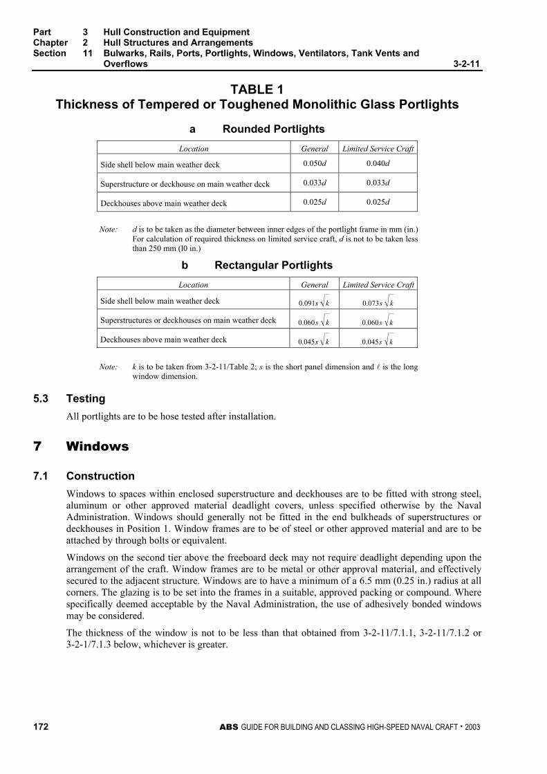
Part 3 Hull Construction and Equipment Chapter 2 Hull Structures and Arrangements Section 11 Bulwarks, Rails, Ports, Portlights, Windows, Ventilators, Tank Vents and
Overflows 3-2-11
172 ABS GUIDE FOR BUILDING AND CLASSING HIGH-SPEED NAVAL CRAFT . 2003
TABLE 1 Thickness of Tempered or Toughened Monolithic Glass Portlights
a Rounded Portlights Location General Limited Service Craft
Side shell below main weather deck 0.050d 0.040d
Superstructure or deckhouse on main weather deck 0.033d 0.033d
Deckhouses above main weather deck 0.025d 0.025d
Note: d is to be taken as the diameter between inner edges of the portlight frame in mm (in.)
For calculation of required thickness on limited service craft, d is not to be taken less than 250 mm (l0 in.)
b Rectangular Portlights Location General Limited Service Craft
Side shell below main weather deck ks091.0 ks073.0
Superstructures or deckhouses on main weather deck ks060.0 ks060.0
Deckhouses above main weather deck ks045.0 ks045.0
Note: k is to be taken from 3-2-11/Table 2; s is the short panel dimension and l is the long
window dimension.
5.3 Testing All portlights are to be hose tested after installation.
7 Windows
7.1 Construction Windows to spaces within enclosed superstructure and deckhouses are to be fitted with strong steel, aluminum or other approved material deadlight covers, unless specified otherwise by the Naval Administration. Windows should generally not be fitted in the end bulkheads of superstructures or deckhouses in Position 1. Window frames are to be of steel or other approved material and are to be attached by through bolts or equivalent.
Windows on the second tier above the freeboard deck may not require deadlight depending upon the arrangement of the craft. Window frames are to be metal or other approval material, and effectively secured to the adjacent structure. Windows are to have a minimum of a 6.5 mm (0.25 in.) radius at all corners. The glazing is to be set into the frames in a suitable, approved packing or compound. Where specifically deemed acceptable by the Naval Administration, the use of adhesively bonded windows may be considered.
The thickness of the window is not to be less than that obtained from 3-2-11/7.1.1, 3-2-11/7.1.2 or 3-2-1/7.1.3 below, whichever is greater.
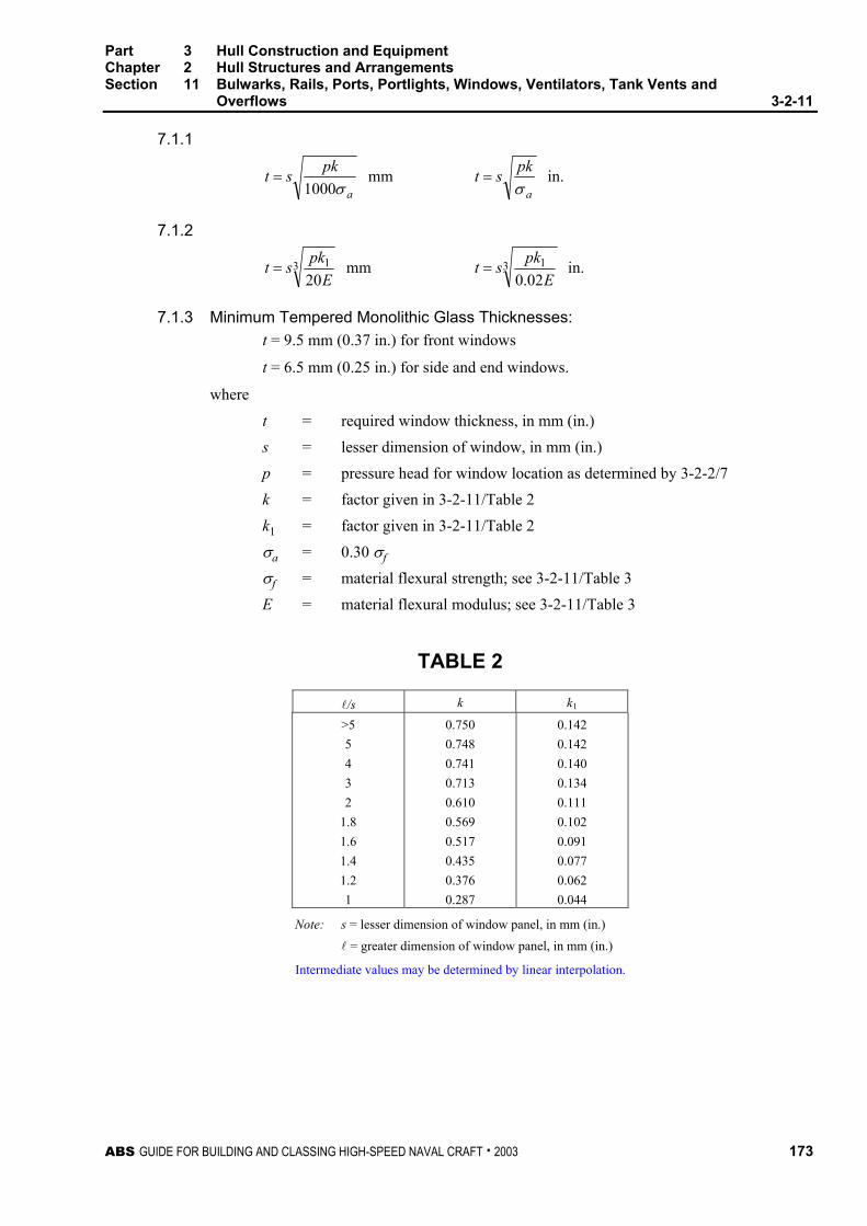
Part 3 Hull Construction and Equipment Chapter 2 Hull Structures and Arrangements Section 11 Bulwarks, Rails, Ports, Portlights, Windows, Ventilators, Tank Vents and
Overflows 3-2-11
ABS GUIDE FOR BUILDING AND CLASSING HIGH-SPEED NAVAL CRAFT . 2003 173
7.1.1
a
pkstσ1000
= mm a
pkstσ
= in.
7.1.2
3 120Epkst = mm 3 1
02.0 Epkst = in.
7.1.3 Minimum Tempered Monolithic Glass Thicknesses: t = 9.5 mm (0.37 in.) for front windows
t = 6.5 mm (0.25 in.) for side and end windows.
where
t = required window thickness, in mm (in.) s = lesser dimension of window, in mm (in.) p = pressure head for window location as determined by 3-2-2/7 k = factor given in 3-2-11/Table 2 k1 = factor given in 3-2-11/Table 2 σa = 0.30 σf σf = material flexural strength; see 3-2-11/Table 3 E = material flexural modulus; see 3-2-11/Table 3
TABLE 2
l/s k k1
>5 5 4 3 2
1.8 1.6 1.4 1.2 1
0.750 0.748 0.741 0.713 0.610 0.569 0.517 0.435 0.376 0.287
0.142 0.142 0.140 0.134 0.111 0.102 0.091 0.077 0.062 0.044
Note: s = lesser dimension of window panel, in mm (in.)
l = greater dimension of window panel, in mm (in.)
Intermediate values may be determined by linear interpolation.

Part 3 Hull Construction and Equipment Chapter 2 Hull Structures and Arrangements Section 11 Bulwarks, Rails, Ports, Portlights, Windows, Ventilators, Tank Vents and
Overflows 3-2-11
174 ABS GUIDE FOR BUILDING AND CLASSING HIGH-SPEED NAVAL CRAFT . 2003
TABLE 3
Glazing
Flexural Strength
Flexural Modulus
Tempered Monolithic
119 MPa (17,200 psi)
73,000 MPa (10,600,000 psi)
Laminated Glass
69 MPa (10,000 psi)
2,620 MPa (380,000 psi)
Polycarbonate* 93 MPa (13,500 psi)
2,345 MPa (340,000 psi)
Acrylic (PMMA)*
110 MPa (16,000 psi)
3,000 MPa (435,000 psi)
* Indicated values are for reference. Aging effects are to be considered for design.
7.3 Testing All windows are to be hose tested after installation
9 Ventilators, Tank Vents and Overflows (1 January 2004)
9.1 General Ventilators are to comply with the requirements of 3-2-11/9.3. Tank vents and overflows are to comply with the requirements in 3-2-11/9.5. In addition, for those located on the fore deck of craft with length L (as defined in 3-1-1/3) not less then 80 meters (263 feet), the requirements given in 3-2-11/9.7 are to be complied with.
9.3 Ventilators
9.3.1 Coaming Construction Ventilators on exposed freeboard decks, superstructure decks, or deckhouses are to have coamings of steel or equivalent material. Coaming plate thicknesses for steel are to be obtained from the following equation:
t = 0.01d + 5.5 mm t = 0.01d + 0.22 in.
where
t = thickness of coaming, in mm (in.)
d = diameter of ventilator, in mm (in.), but not less than 200 mm (7.5 in.)
The maximum steel coaming plate thickness required is 10 mm (0.40 in.). The coamings are to be effectively secured to the deck. Coamings which are more than 900 mm (35.5 in.) high and which are not supported by adjacent structures are to have additional strength and attachment. Ventilators passing through superstructures other than enclosed superstructures are to have substantially constructed coamings of steel or equivalent material at the freeboard deck. Coaming plate thickness of material other than steel will be specially considered.
9.3.2 Coaming Height Ventilators in Position 1 are to have coamings at least 900 mm (35.5 in.) high. Ventilators in Position 2 are to have coamings at least 760 mm (30 in.) high. For definitions of Position 1 and Position 2, see 3-2-9/3. When requested by the Naval Administration, a reduction of the required coaming heights may be considered.

Part 3 Hull Construction and Equipment Chapter 2 Hull Structures and Arrangements Section 11 Bulwarks, Rails, Ports, Portlights, Windows, Ventilators, Tank Vents and
Overflows 3-2-11
ABS GUIDE FOR BUILDING AND CLASSING HIGH-SPEED NAVAL CRAFT . 2003 175
9.3.3 Means for Closing Ventilators Except as provided below, ventilator openings are to be provided with efficient, permanently attached closing appliances. In craft measuring 24 m (79 ft) or more in length (as defined in the International Convention on Load Lines, 1966), ventilators in Position 1, the coamings of which extend to more than 4.5 m (14.8 ft) above the deck and in Position 2, the coamings of which extend to more than 2.3 m (7.5 ft) above the deck, need not be fitted with closing arrangements.
These coaming height requirements may be modified in craft measuring less than 24 m (79 ft) in length.
9.3.4 Ventilators in Way of Own-craft Weapons-firing Effects Typically, ventilation system intakes and exhausts should be located outside the blast area. Where arrangements do not permit this, intakes and exhausts may be located in the blast area if fitted with blast shields, which withstand the blast. Supply ventilation weather openings within 15 m (50 ft) of a missile launcher or end of a gun muzzle are to be fitted with an automatically operated ventilation damper that will prevent the ingestion of gun propellant and missile exhaust gases into the craft. Ventilation system exhausts serving flammable liquid storerooms or issue rooms are not to be located in missile blast zones.
9.5 Tank Vents and Overflows Tank vents and overflows are to be in accordance with the requirements of 4-6-4/9.3 and 4-6-4/9.5 of this Guide and, where applicable, the requirements given below in 3-2-11/9.7.
9.7 Ventilators, Tank Vents and Overflows on the Fore Deck
9.7.1 Application The requirements of this paragraph applies to all ventilators, tank vents and overflows located on the exposed fore deck within the forward 0.25L on craft with length L (as defined in 3-1-1/3) not less then 80 meters (263 feet) and where the height of the exposed deck in way of the item is less than 0.1L or 22 meters (72 ft) above the summer load waterline, whichever is the lesser.
9.7.2 Applied Loading to the Air Pipes and Ventilators 9.7.2(a) Pressure. The pressures p, in kN/m2 (tf/m2, Ltf/ft2), acting on air pipes, ventilator pipes and their closing devices, may be calculated from:
p = f ρ V2 Cd Cs Cp kN/m2 (tf/m2, Ltf/ft2)
where:
f = 0.5 (0.05, 0.0156)
ρ = density of sea water, 1.025 t/m3 (1.025 t/m3, 0.0286 Lt/ft3)
V = velocity of water over the fore deck, 13.5 m/sec (44.3 ft/sec)
Cd = shape coefficient
= 0.5 for pipes,
= 1.3 for pipes or ventilator heads in general,
= 0.8 for pipes or ventilator heads of cylindrical form with its axis in the vertical direction
Cs = slamming coefficient, 3.2

Part 3 Hull Construction and Equipment Chapter 2 Hull Structures and Arrangements Section 11 Bulwarks, Rails, Ports, Portlights, Windows, Ventilators, Tank Vents and
Overflows 3-2-11
176 ABS GUIDE FOR BUILDING AND CLASSING HIGH-SPEED NAVAL CRAFT . 2003
Cp = protection coefficient:
= 0.7 for pipes and ventilator heads located immediately behind a breakwater or forecastle,
= 1.0 elsewhere including immediately behind a bulwark.
9.7.2(b) Force. Forces acting in the horizontal direction on the pipe and its closing device may be calculated from the above pressure using the largest projected area of each component.
9.7.3 Strength Requirements for Ventilators, Tank Vents and Overflows and their Closing Devices 9.7.3(a) Bending Moment and Stress. Bending moments and stresses in air pipes and ventilator pipes are to be calculated at critical positions: at penetration pieces, at weld or flange connections, at toes of supporting brackets. Bending stresses in the net section are not to exceed 0.8Y, where Y is the specified minimum yield stress or 0.2% proof stress of the steel at room temperature. Irrespective of corrosion protection, a corrosion addition to the net section of 2.0 mm (0.08 in.) is then to be applied.
9.7.3(b) Tank Vents and Overflows
i) For standard tank vents and overflows of 760 mm (30 in.) height closed by heads of not more than the tabulated projected area, pipe thicknesses and bracket heights are specified in 3-2-14/Table 4. Where brackets are required, three or more radial brackets are to be fitted.
ii) Brackets are to be of gross thickness of 8 mm (0.32 in.) or more, of minimum length of 100 mm (4.0 in.), and height according to 3-2-11/Table 4, but need not extend over the joint flange for the head. Bracket toes at the deck are to be suitably supported.
iii) For other configurations, loads according to 3-2-11/9.7.2 are to be applied, and means of support determined in order to comply with the requirements above. Brackets, where fitted, are to be of suitable thickness and length according to their height.
iv) Final (gross) pipe thickness is not to be taken less than as indicated in 4-6-4/9.3.2 and 4-6-4/9.5.6
v) The minimum internal diameter of the air pipe or overflow is not to be less than 65 mm.
9.7.3(c) Ventilators
i) For standard ventilators of 900 mm (35.4 in.) height closed by heads of not more than the tabulated projected area, pipe thicknesses and bracket heights are specified in 3-2-14/Table 5. Brackets, where required, are to be as specified in 3-2-11/9.7.3(b)iii).
ii) For ventilators of height greater than 900 mm (35.4 in.), brackets or alternative means of support are to be provided. Coaming is not to be taken less than as indicated in 3-2-11/9.3 nor in 3-2-11/Table 4.
9.7.3(d) Components and Connections. All component parts and connections of the tank vents and overflows or ventilators are to be capable of withstanding the loads defined in 3-2-11/9.7.2.
9.7.3(e) Rotary Heads. Rotating type mushroom ventilator heads are not to be used for application in this location.
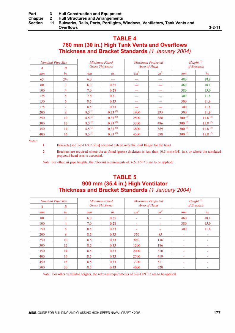
Part 3 Hull Construction and Equipment Chapter 2 Hull Structures and Arrangements Section 11 Bulwarks, Rails, Ports, Portlights, Windows, Ventilators, Tank Vents and
Overflows 3-2-11
ABS GUIDE FOR BUILDING AND CLASSING HIGH-SPEED NAVAL CRAFT . 2003 177
TABLE 4 760 mm (30 in.) High Tank Vents and Overflows
Thickness and Bracket Standards (1 January 2004)
Nominal Pipe Size A B
Minimum Fitted Gross Thickness
Maximum Projected Area of Head
Height (1) of Brackets
mm in. mm in. cm2 in2 mm in.
65 21/2 6.0 --- --- --- 480 18.9 80 3 6.3 0.25 --- --- 460 18.1
100 4 7.0 0.28 --- --- 380 15.0 125 5 7.8 0.31 --- --- 300 11.8 150 6 8.5 0.33 --- --- 300 11.8 175 7 8.5 0.33 --- --- 300 11.8 200 8 8.5 (2) 0.33 (2) 1900 295 300 11.8 250 10 8.5 (2) 0.33 (2) 2500 388 300 (2) 11.8 (2)
300 12 8.5 (2) 0.33 (2) 3200 496 300 (2) 11.8 (2) 350 14 8.5 (2) 0.33 (2) 3800 589 300 (2) 11.8 (2) 400 16 8.5 (2) 0.33 (2) 4500 698 300 (2) 11.8 (2)
Notes: 1 Brackets [see 3-2-11/9.7.3(b)] need not extend over the joint flange for the head.
2 Brackets are required where the as fitted (gross) thickness is less than 10.5 mm (0.41 in.), or where the tabulated projected head area is exceeded.
Note: For other air pipe heights, the relevant requirements of 3-2-11/9.7.3 are to be applied.
TABLE 5 900 mm (35.4 in.) High Ventilator
Thickness and Bracket Standards (1 January 2004)
Nominal Pipe Size A B
Minimum Fitted Gross Thickness
Maximum Projected Area of Head
Height (1) of Brackets
mm in. mm in. cm2 in2 mm in.
80 3 6.3 0.25 - - 460 18.1 100 4 7.0 0.28 - - 380 15.0 150 6 8.5 0.33 - - 300 11.8 200 8 8.5 0.33 550 85 - - 250 10 8.5 0.33 880 136 - -
300 12 8.5 0.33 1200 186 - - 350 14 8.5 0.33 2000 310 - - 400 16 8.5 0.33 2700 419 - - 450 18 8.5 0.33 3300 511 - - 500 20 8.5 0.33 4000 620 - -
Note: For other ventilator heights, the relevant requirements of 3-2-11/9.7.3 are to be applied.

This Page Intentionally Left Blank

ABS GUIDE FOR BUILDING AND CLASSING HIGH-SPEED NAVAL CRAFT . 2003 179
P A R T
3 C H A P T E R 2 Hull Structures and Arrangements
S E C T I O N 12 Protective Coatings
1 General
The extent, type, and amount of coating are to be specified by the Naval Administration. No final painting or coating is to be performed until all surveys and testing have been completed. All areas not being coated are to be protected during painting, and upon completion of the work any paint accidentally applied to the areas are to be removed.
3 Preparation
Surfaces that are to be painted are to be completely free of rust, loose paint, dirt, scale, oil, grease, salt deposits, and moisture. Protective coatings are to be applied as soon as practical after cleaning before corrosion or soil forms on the cleaned surface.
If more than seven days elapse between epoxy coats, the surface should be cleaned prior to an application of a tack coat (1-2 wet mils) before the application of the next full coat.
5 Protection of Steel
5.1 Preparation All steel surfaces that will be coated are to be abrasive blast cleaned. Prior to abrasive blast cleaning, surfaces contaminated with oil or grease are to be cleaned and weld splatters, slag, and flux compounds are to be removed by grinding, sanding, or chipping. In areas where abrasive blasting is not feasible, the surfaces are to be cleaned by mechanical means to remove foreign matter.
Galvanized steels shall be roughened with a light abrasive blast or by mechanical means prior to painting.
5.3 All Spaces Unless otherwise approved, all steel work is to be suitably coated with paint or equivalent.
5.5 Salt Water Ballast Space Tanks or holds for salt water ballast are to have a corrosion-resistant hard type coating such as epoxy or zinc on all structural surfaces. Where a long retention of salt water is expected due to the type of craft or unit, special consideration for the use of inhibitors or sacrificial anodes may be given.
Part 3 Hull Construction and Equipment Chapter 2 Hull Structures and Arrangements Section 12 Protective Coatings 3-2-12
180 ABS GUIDE FOR BUILDING AND CLASSING HIGH-SPEED NAVAL CRAFT . 2003
5.7 Oil Spaces Tanks intended for oil need not be coated.
7 Protection of Aluminum
7.1 General Aluminum alloys intended for hull construction are to be used generally only under conditions that will not induce excessive corrosion. Where exposure to environment that would induce excessive corrosion is expected, suitable coatings, tapes, sacrificial anodes, impressed-current systems or other corrosion prevention measures are to be used. When tapes are used for corrosion protection, they are to be non-wicking and non-water absorbing. Grease containing graphite is not to be used with aluminum, instead, zinc or other suitable base grease is to be used.
7.3 Preparation All aluminum surfaces that will be coated are to be thoroughly cleaned to bare metal, free of corrosion products, dirt, and other contaminants, by light abrasive blasting. Spot cleaning after blasting can be done by power brushing or orbital sanding.
7.5 Coatings Coatings are to be applied in accordance with the manufacturer’s instructions, and are to be preceded by appropriate cleaning and possibly chemical conversion of surfaces as may be required in accordance with the manufacturer’s recommendations. Coatings are to be free from voids, scratches or other imperfections that are potential sites for localized corrosion.
The composition of coatings is to be compatible with aluminum. Coatings containing copper, lead, mercury or other metals that can induce galvanic or other forms of corrosion are not to be used. Zinc chromate coatings may be used. Insulating coatings intended to prevent galvanic corrosion are not to contain graphite or other conducting materials.
7.7 Faying Surfaces – Aluminum to Aluminum Aluminum faying surfaces that will be exposed to weather, seawater, or other corrosive environment are to be suitable coated to minimize crevice corrosion in way of the faying surfaces.
7.9 Faying Surface between Aluminum and Other Metals
7.9.1 Hull Suitable means are to be taken to avoid direct contact of faying surfaces of aluminum to other metals. When such faying surfaces occur in hull construction, suitable non-wicking and non-water absorbing insulation tapes or coatings are to be used. Faying surfaces between mechanically fastened metal components, except machinery foundations, are to be protected by the use of bedding compounds or adhesives. Other types of joints between aluminum and other metals may be approved in certain applications.
7.9.2 Piping Suitable means, such as special pipe hangers, are to be used to avoid conductive connections between aluminum hulls and non-aluminum metal piping systems. Where watertightness is required, such as when piping passes through bulkheads, decks, tanktops, and shell, special fittings will be required to maintain isolation between dissimilar metals.

Part 3 Hull Construction and Equipment Chapter 2 Hull Structures and Arrangements Section 12 Protective Coatings 3-2-12
ABS GUIDE FOR BUILDING AND CLASSING HIGH-SPEED NAVAL CRAFT . 2003 181
7.9.3 Bearing Areas Bearing areas such as engine beds, pump foundations, propeller shafts, rudder and other appendages of metals other than aluminum are to be suitably isolated by such means as non-metallic bearing casing, non-conductive packing (not containing graphite or other conductors) or suitable tapes and coatings. Alternative methods for minimizing corrosion at these locations will be specially considered. Wicking-type tapes or water-absorbing packing materials such as canvas should not be used. The metals used for such applications are to be selected to minimize galvanic effects; stainless steels are to be considered. The use of copper-base alloys such as brass or bronze is generally not recommended where galvanic corrosion is of concern, and these materials may only be used when specially approved. In those cases where the use of dissimilar metals cannot be avoided, or where galvanic corrosion is of concern, such as in wet tanks, a suitable sacrificial anode or impressed current system should be installed.
7.11 Faying Surface between Aluminum and Non-metals Aluminum in contact with wood or insulating-type material is to be protected from the corrosive effects of the impurities in these materials by a suitable coating or covering. Concrete used with aluminum is to be free of additives for cold weather pouring. Preformed glass insulation is recommended for piping insulation. Any adhesives which may be used to connect insulation to aluminum are to be free of agents that would be corrosive to aluminum. Foaming agents harmful to aluminum, such as Freon, are not to be used for insulating foams. Areas where dirt or soot is likely to collect and remain for prolonged periods are to be protected from pitting corrosion by the use of coatings or other suitable means.
7.13 Corrosion of Wet Spaces Suitable means are to be used to avoid arrangements that could induce crevice corrosion in wet spaces. In bilge spaces, chain lockers, and similar locations where exfoliation corrosion may be of concern, appropriate materials suitably heat treated for resistance to this form of corrosion are to be employed.
7.15 Service at Elevated Temperatures For service temperatures of 66°C (150°F) or above, only aluminum alloys and filler metals specially designated for service at these temperatures are to be used.
7.17 Cathodic Protection for Corrosion Prevention For application where corrosion is of concern, consideration is to be given to the use of sacrificial anode or impressed current systems of corrosion control. Details of sacrificial anodes and arrangements are to be submitted for review. Anodes are to be in accordance with ASTM or other recognized standard, as specified by the Naval Administration. When impressed current systems are used, adequate precautions are to be taken that the negative voltage is not excessive.
7.19 Stray Current Protection Precautions are to be taken when in dock to prevent stray currents from welding power or other sources from adversely affecting the aluminum. Whenever possible, the cathodic protection system of the craft should be in place and operating when the craft is in the water. A.C. power sources are to be insulated from the hull. For battery and other D.C. power sources, grounding is to be avoided if possible. Where safety considerations require grounding to the hull, the negative pole is to be connected to the hull.

Part 3 Hull Construction and Equipment Chapter 2 Hull Structures and Arrangements Section 12 Protective Coatings 3-2-12
182 ABS GUIDE FOR BUILDING AND CLASSING HIGH-SPEED NAVAL CRAFT . 2003
7.21 Bi-material Joints Such joints, when used, may be required to be appropriately painted, coated, wrapped or protected by other methods to prevent galvanic corrosion. Where aluminum is to be joined to other materials, each faying surface is to be suitably coated to minimize corrosion. In addition, when one or both sides of an aluminum or steel connection to dissimilar metal joints are exposed to weather, sea water, or wet spaces, a minimum of 0.5 mm (0.02 in.) of suitable insulation is to be installed between faying surfaces and extended beyond the edge of the joint. Non-welded oil or water stops are to be of plastic insulation tape or equivalent which would provide a suitably corrosion resistant system. Insulating materials are to be non-porous and have mechanical properties suitable for the application.
9 Protection of Fiber Reinforced Plastic
9.1 General Cured gel-coat resins and lay-up resin are to be highly resistant to water and other liquid absorption; appropriate materials, lay-up, and lay-up procedures are to be used and manufacturer’s recommendations followed to attain this. Care is to be taken in the use of laminates containing carbon fibers so that they are not close to or do not induce galvanic corrosion with metal fittings.
9.3 Preparation Composite surfaces that are not coated in the mold are to be sanded lightly to remove any foreign matter. Care is to be taken not to expose any of the structural glass. Surfaces are to be cleaned with water and solvent to ensure the removal of residual mold release compound, oil, or grease.
9.5 Tanks In water, fuel oil, or other approved tanks, the resins used are to be compatible with the contents of the tanks; the contents of the tanks are not to affect the cured properties of the tank laminate. The cured laminate is to be highly resistant to absorption of the liquid, and is not to have harmful, deleterious, or undesirable effects on the contents of the tank. The tank is generally to be gel-coated on the inside. See also 3-2-5/5.1.
9.7 Cathodic Protection Cathodic protection is to be provided where shaft struts, propeller shafts, propellers, rudders, fittings, etc. are constructed of manganese bronze, brass, stainless steel or mild steel. Details of the sacrificial anodes and arrangements are to be submitted for review. Anodes are to be in accordance with ASTM or other recognized standard, as specified by the Naval Administration.

ABS GUIDE FOR BUILDING AND CLASSING HIGH-SPEED NAVAL CRAFT . 2003 183
P A R T
3 C H A P T E R 2 Hull Structures and Arrangements
S E C T I O N 13 Welding, Forming and Weld Design
1 Fillet Welds
1.1 General Fillet welds may be made by an approved manual, semi automatic or automatic process. The sizes of fillet welds are subject to approval in each case, and are to be indicated on detail drawings or on a separate welding schedule. The Naval Administration may specify a greater extent of continuous welding. Consideration will also be given to a lesser extent of continuous welding when specified by the Naval Administration. When terminating an aluminum weld, either continuous or intermittent, crater filling by back stepping is recommended to provide a sound ending for each fillet.
1.3 Tee Connections In general, the required size and spacing of the fillets is to be as given in 3-2-13/1.5. Special consideration will be given where there is a substantial difference between the thickness of members being connected. Where the opening between members exceeds 1.0 mm (0.04 in.) and is not greater than 5 mm (0.1875 in.), the size of the fillets is to be increased by the amount of the opening. Spacing between plates forming tee joints is not to exceed 5 mm (0.1875 in.).
1.5 Fillet Sizes and Spacing Tee connections are to be formed by continuous or intermittent fillet welds on each side, the leg size, w, of the fillet welds is to be obtained from the following equations:
w = tp × C × l
s + 1.5 mm w = tp × C × l
s + 0.06 in.
where
w = size of the weld leg, in mm (in.)
l = actual length of the weld fillet, clear of crater, in mm (in.). See 3-2-13/Figure 1
s = distance between centers of weld fillets, in mm (in.). See 3-2-13/Figure 1
tp = thickness of the thinner of the two members being joined, in mm (in.)
C = weld factor given in 3-2-13/Table 1
w is not to be taken less than 0.3tp or 3.5 mm (0.14 in.), whichever is greater.
The throat thickness of the fillet is to be not less than 0.7w.

Part 3 Hull Construction and Equipment Chapter 2 Hull Structures and Arrangements Section 13 Welding, Forming and Weld Design 3-2-13
184 ABS GUIDE FOR BUILDING AND CLASSING HIGH-SPEED NAVAL CRAFT . 2003
In calculating weld factors, the leg length of matched fillet weld is to be taken as the designated leg length or 0.7tp + 2.0 mm (0.7tp + 0.08 in.), whichever is less.
Where it is intended to use continuous fillet welding, the leg size of fillet welds is to be obtained from the above equations taking s/l equal to 1.
For intermittent welding with plate thickness less than 7 mm (0.28 in.) welds are to be staggered.
1.7 Thin Plating For plating of 6.5 mm (0.25 in.) or less, the requirements of 3-2-19/1.5 may be modified as follows:
W = tpl × C × l
s + 2.0[1.25 – (l/s)] mm
W = tpl × C × l
s + 0.08[1.25 – (l/s)] in.
Wmin = 3.5 mm (0.14 in.)
For plates less than 4.5 mm (0.1875 in.), welds less than required above will be considered when requested by the Naval Administration depending upon the location and quality control procedure.
1.9 Length and Arrangement of fillet Where an intermittent weld is permitted by 3-2-13/Table 1, the length of each fillet weld is to be not less than 75 mm (3 in.) for tpl of 7 mm (0.28 in.) or more, nor less than 65 mm (2.5 in.) for lesser tpl.
The unwelded length is to be not more than 32 tpl.
1.11 Fillet Weld Arrangements
1.11.1 Intersections Where beams, stiffeners, frames, etc., are intermittently welded and pass through slotted girders, shelves or stringers, there is to be a pair of matched intermittent welds on each side of each such intersection and the beams, stiffeners and frames are to be efficiently attached to the girders, shelves and stringers. The length of the matched intermittent fillet welds is to be 0.125 times the length of the joint or 100 mm (4 in.), whichever is greater.
1.11.2 Unbracketed End Attachments Unbracketed beams, frames, etc. and stiffeners of watertight and tank bulkheads and superstructure and house fronts are to have double continuous welds for length at each end equal to the depth of the member but not less than 0.125 times the length of the joint or 100 mm (4 in.), whichever is greater.
1.11.3 Bracketed End Attachments Frames, beams, stiffeners etc. are to be lapped onto the bracket a length not less than 1.5 times the depth of the member, and are to have continuous fillet welds all around. Lapped end connections of longitudinal strength members are also to have a throat size, t, such that the total effective area of the lap welding is not less than the area of the member being attached.
1.11.4 Lapped Joints Lapped joints are typically not to be used in structural applications or on plates greater than 6 mm (0.25 in.) thick, unless specially approved.
Lapped joints are generally to have a width of overlap not less than twice the thickness of thinner plate plus 25 mm (1 in.) with welds on both edges of the sizes required by 3-2-13/1.5.

Part 3 Hull Construction and Equipment Chapter 2 Hull Structures and Arrangements Section 13 Welding, Forming and Weld Design 3-2-13
ABS GUIDE FOR BUILDING AND CLASSING HIGH-SPEED NAVAL CRAFT . 2003 185
1.11.5 Plug Welds or Slot Welds Plug welds or slot welds are to be specially approved for particular applications. When approved, an appropriate demonstration that adequate weld penetration and soundness is achieved is to be made to the Surveyor’s satisfaction. When used in the attachment of doublers and similar applications, plug or slot welds may be spaced at 16 times the doubler thickness, but not more than 300 mm (12 in.) between centers in both directions. In general, elongated slot welds are recommended. For closing plates on rudders, slots are to be 75 mm (3 in.) in length spaced at 150 mm (6 in.) between centers. The periphery of the plugs or slots are to be fillet welded, of fillet size, w, generally not less than 0.70 times the plate thickness. Plugs and slots are not to be filled with welded deposit.
3 Bi-material Joints
Techniques required for joining two different materials will be subject to special consideration. The use of explosion bonding may be considered depending on the application and the mechanical and corrosive properties of the joint.
5 Alternatives
The foregoing are considered minimum requirements for welding in hull construction, but alternative methods, arrangements and details will be considered for approval.
FIGURE 1
Staggered Chained
S
w
wt
SS
l
w = leg size in mm (in.) t = throat size in mm (in.)
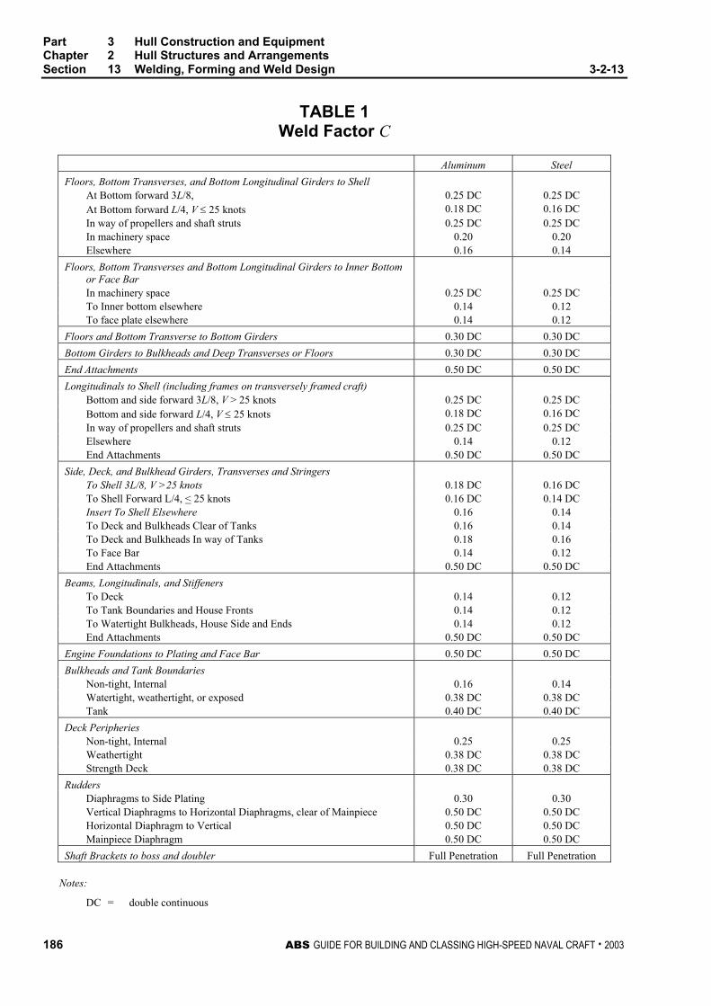
Part 3 Hull Construction and Equipment Chapter 2 Hull Structures and Arrangements Section 13 Welding, Forming and Weld Design 3-2-13
186 ABS GUIDE FOR BUILDING AND CLASSING HIGH-SPEED NAVAL CRAFT . 2003
TABLE 1 Weld Factor C
Aluminum Steel Floors, Bottom Transverses, and Bottom Longitudinal Girders to Shell
At Bottom forward 3L/8, 0.25 DC 0.25 DC At Bottom forward L/4, V ≤ 25 knots 0.18 DC 0.16 DC In way of propellers and shaft struts 0.25 DC 0.25 DC In machinery space 0.20 0.20 Elsewhere 0.16 0.14
Floors, Bottom Transverses and Bottom Longitudinal Girders to Inner Bottom or Face Bar
In machinery space 0.25 DC 0.25 DC To Inner bottom elsewhere 0.14 0.12 To face plate elsewhere 0.14 0.12
Floors and Bottom Transverse to Bottom Girders 0.30 DC 0.30 DC Bottom Girders to Bulkheads and Deep Transverses or Floors 0.30 DC 0.30 DC End Attachments 0.50 DC 0.50 DC Longitudinals to Shell (including frames on transversely framed craft)
Bottom and side forward 3L/8, V > 25 knots 0.25 DC 0.25 DC Bottom and side forward L/4, V ≤ 25 knots 0.18 DC 0.16 DC In way of propellers and shaft struts 0.25 DC 0.25 DC Elsewhere 0.14 0.12 End Attachments 0.50 DC 0.50 DC
Side, Deck, and Bulkhead Girders, Transverses and Stringers To Shell 3L/8, V >25 knots 0.18 DC 0.16 DC To Shell Forward L/4, < 25 knots 0.16 DC 0.14 DC Insert To Shell Elsewhere 0.16 0.14 To Deck and Bulkheads Clear of Tanks 0.16 0.14 To Deck and Bulkheads In way of Tanks 0.18 0.16 To Face Bar 0.14 0.12 End Attachments 0.50 DC 0.50 DC
Beams, Longitudinals, and Stiffeners To Deck 0.14 0.12 To Tank Boundaries and House Fronts 0.14 0.12 To Watertight Bulkheads, House Side and Ends 0.14 0.12 End Attachments 0.50 DC 0.50 DC
Engine Foundations to Plating and Face Bar 0.50 DC 0.50 DC Bulkheads and Tank Boundaries
Non-tight, Internal 0.16 0.14 Watertight, weathertight, or exposed 0.38 DC 0.38 DC Tank 0.40 DC 0.40 DC
Deck Peripheries Non-tight, Internal 0.25 0.25 Weathertight 0.38 DC 0.38 DC Strength Deck 0.38 DC 0.38 DC
Rudders Diaphragms to Side Plating 0.30 0.30 Vertical Diaphragms to Horizontal Diaphragms, clear of Mainpiece 0.50 DC 0.50 DC Horizontal Diaphragm to Vertical 0.50 DC 0.50 DC Mainpiece Diaphragm 0.50 DC 0.50 DC
Shaft Brackets to boss and doubler Full Penetration Full Penetration
Notes:
DC = double continuous

ABS GUIDE FOR BUILDING AND CLASSING HIGH-SPEED NAVAL CRAFT . 2003 187
P A R T
3 C H A P T E R 2 Hull Structures and Arrangements
A P P E N D I X 1 Guidelines for Calculating Bending Moment and Shear Force in Rudders and Rudder Stocks
1 Application
Bending moments, shear forces and reaction forces of rudders, stocks and bearings may be calculated according to this Appendix for the types of rudders indicated. Moments and forces on rudders of different types or shapes than those shown are to be calculated using alternative methods and will be specially considered.
3 Spade Rudders
3.1 Rudder
3.1.1 Shear Force
Lateral shear force, V(z), at a horizontal section of the rudder z meters (feet) above the bottom of lR is given by the following equation:
V(z) = A
zCR [cl + R
zl2
(cu − cl)] kN (tf, Ltf )
where
z = distance from the bottom of lR to the horizontal section under consideration, in m (ft). See 3-2-A1/Figure 1
CR = rudder force, as defined in 3-2-8/3.1, in kN (tf, Ltf )
A = rudder blade area, in m2 (ft2)
cl, cu and lR are dimensions as indicated in 3-2-A1/Figure 1, in m (ft).

Part 3 Hull Construction and Equipment Chapter 2 Hull Structures and Arrangements Appendix 1 Guidelines in Calculating Bending Moment & Shear Force in Rudders
& Rudder Stocks 3-2-A1
188 ABS GUIDE FOR BUILDING AND CLASSING HIGH-SPEED NAVAL CRAFT . 2003
3.1.2 Bending Moment
Bending moment, M(z), at a horizontal section z meters (feet) above the baseline of the rudder is given by the following equation:
M(z) = ACz R
2
2 [cl +
R
zl3
(cu − cl)] kN-m, (tf-m, Ltf-ft)
where z, CR, A, cl, cu and lR are as defined in 3-2-A1/3.1.1.
3.3 Lower Stock
3.3.1 Shear Force
Lateral shear force at any section of the lower stock between the top of the rudder and the neck bearing, Vl, is given by the following equation:
Vl = CR kN (tf, Ltf)
where CR is rudder force, as defined in 3-2-A1/3.1.1.
3.3.2 Bending Moment at Neck Bearing
The bending moment in the rudder stock at the neck bearing, Mn, is given by the following equation:
Mn = CR [ll + )(3
)2(
u
uRcc
cc+
+
l
ll ] kN-m (tf-m, Ltf-ft )
where
CR = rudder force as defined in 3-2-A1/3.1.1
cl, cu, ll and lR are dimensions as indicated in 3-2-A1/Figure 1, in m (ft).
3.5 Moment at Top of Upper Stock Taper
The bending moment in the upper rudder stock at the top of the taper, Mt, is given by the following equation:
Mt = CR [ll + )(3
)2(
u
uRcc
cc+
+
l
ll ] × [ u
tRu zl
lll l )( −++ ] kN-m (tf-m, Ltf-ft)
where
zt = distance from the rudder baseline to the top of the upper rudder stock taper in m (ft)
CR = rudder force, as defined in 3-2-A1/3.1.1
cl, cu, ll, lu and lR are dimensions as indicated in 3-2-A1/Figure 1, in m (ft).
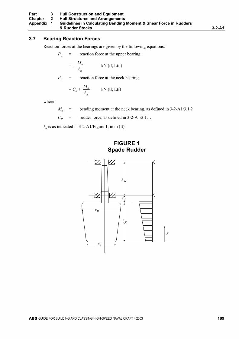
Part 3 Hull Construction and Equipment Chapter 2 Hull Structures and Arrangements Appendix 1 Guidelines in Calculating Bending Moment & Shear Force in Rudders
& Rudder Stocks 3-2-A1
ABS GUIDE FOR BUILDING AND CLASSING HIGH-SPEED NAVAL CRAFT . 2003 189
3.7 Bearing Reaction Forces
Reaction forces at the bearings are given by the following equations:
Pu = reaction force at the upper bearing
= − u
nMl
kN (tf, Ltf )
Pn = reaction force at the neck bearing
= CR + u
nMl
kN (tf, Ltf)
where
Mn = bending moment at the neck bearing, as defined in 3-2-A1/3.1.2
CR = rudder force, as defined in 3-2-A1/3.1.1.
lu is as indicated in 3-2-A1/Figure 1, in m (ft).
FIGURE 1 Spade Rudder
Z
u
l
u
l
R
c
c
l
l
l

This Page Intentionally Left Blank
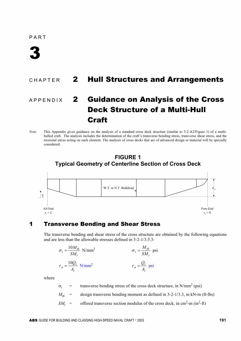
ABS GUIDE FOR BUILDING AND CLASSING HIGH-SPEED NAVAL CRAFT . 2003 191
P A R T
3 C H A P T E R 2 Hull Structures and Arrangements
A P P E N D I X 2 Guidance on Analysis of the Cross Deck Structure of a Multi-Hull Craft
Note: This Appendix gives guidance on the analysis of a standard cross deck structure (similar to 3-2-A2/Figure 1) of a multi-hulled craft. The analysis includes the determination of the craft’s transverse bending stress, transverse shear stress, and the torsional stress acting on each element. The analysis of cross decks that are of advanced design or material will be specially considered.
FIGURE 1 Typical Geometry of Centerline Section of Cross Deck
W.T. or N.T. Bulkhead
Aft Endxi = L
Fore Endxi = 0
dcs
Y
1 Transverse Bending and Shear Stress
The transverse bending and shear stress of the cross structure are obtained by the following equations and are less than the allowable stresses defined in 3-2-1/3.5.3:
t
tbt SM
M10=σ N/mm2
t
tbt SM
M=σ psi
t
ta A
Q10=τ N/mm2
t
ta A
Q=τ psi
where
σt = transverse bending stress of the cross deck structure, in N/mm2 (psi)
Mtb = design transverse bending moment as defined in 3-2-1/3.3, in kN-m (ft-lbs)
SMt = offered transverse section modulus of the cross deck, in cm2-m (in2-ft)
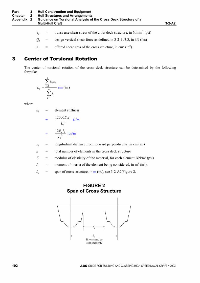
Part 3 Hull Construction and Equipment Chapter 2 Hull Structures and Arrangements Appendix 2 Guidance on Torsional Analysis of the Cross Deck Structure of a
Multi-Hull Craft 3-2-A2
192 ABS GUIDE FOR BUILDING AND CLASSING HIGH-SPEED NAVAL CRAFT . 2003
τa = transverse shear stress of the cross deck structure, in N/mm2 (psi)
Qt = design vertical shear force as defined in 3-2-1-/3.3, in kN (lbs)
At = offered shear area of the cross structure, in cm2 (in2)
3 Center of Torsional Rotation
The center of torsional rotation of the cross deck structure can be determined by the following formula:
∑
∑
=
== n
ii
n
iii
c
k
xkL
1
1 cm (in.)
where
ki = element stiffness
= 312000
i
ii
L
IE N/m
= 312
i
ii
L
IE lbs/in
xi = longitudinal distance from forward perpendicular, in cm (in.)
n = total number of elements in the cross deck structure
E = modulus of elasticity of the material, for each element, kN/m2 (psi)
Ii = moment of inertia of the element being considered, in m4 (in4).
Li = span of cross structure, in m (in.), see 3-2-A2/Figure 2.
FIGURE 2 Span of Cross Structure
Li
Li
If restrained byside shell only

Part 3 Hull Construction and Equipment Chapter 2 Hull Structures and Arrangements Appendix 2 Guidance on Torsional Analysis of the Cross Deck Structure of a
Multi-Hull Craft 3-2-A2
ABS GUIDE FOR BUILDING AND CLASSING HIGH-SPEED NAVAL CRAFT . 2003 193
5 Maximum Bending Stress on Each Element
The maximum bending stress on each element is to be less than the allowable torsional stress defined in 3-2-1/3.5.3
5.1 Deflection The total amount that each element deflects can be determined by the following formula:
∑=
=n
iici
citti
kx
xM
1
2
100000δ m
∑=
= n
iici
citti
kx
xM
1
2
12δ in.
where
δi = deflection of each member, in m (in.)
Mtt = design torsional moment acting upon the transverse structure connecting the hulls, as determined 3-2-1/3.3, in kN-m (ft-lbs)
xci = xi − Lc, in cm (in.)
xi, Lc and ki are as defined in 3-2-A2/1.
5.3 Bending Moment The bending moment that is acting on each element is determined by the following formula:
2ii
iLP
BM =
where
BMi = bending moment that is acting on the element under consideration, in N-m (in-lbs)
Pi = δi ki, force that is acting on the element, in N (lbs)
Li = as defined in 3-2-A2/1
δi = as defined in 3-2-A2/5.1
ki = as defined in 3-2-A2/1
5.5 Maximum Stress The maximum stress that is applied on each element can be determined by the following formula:
i
ii SM
BM1000=σ kN/m2
i
ii SM
BM=σ psi
where
σi = maximum stress that is acting upon the element, in kN/m2 (psi)
BMi = bending moment as defined, in 3-2-A2/5.3
SMi = section modulus of the element being considered, in cm3 (in3)
Part 3 Hull Construction and Equipment Chapter 2 Hull Structures and Arrangements Appendix 2 Guidance on Torsional Analysis of the Cross Deck Structure of a
Multi-Hull Craft 3-2-A2
194 ABS GUIDE FOR BUILDING AND CLASSING HIGH-SPEED NAVAL CRAFT . 2003
5.7 Maximum Shear Stress on Each Element The maximum shear stress on each element is to be less than the allowable transverse shear stress defined in 3-2-1/3.5.3.
wi
ii A
P10=τ kN/m2
wi
ii A
P=τ psi
where
τi = maximum shear stress that is acting upon the element, in kN/m2 (psi)
Pi = force acting upon the element, in N (lbs), as defined in 3-2-A2/5.3
Awi = area of the web of the element being considered, in cm2 (in2)

ABS PROPOSED RULES FOR BUILDING AND CLASSING HIGH-SPEED CRAFT . 2003 195
P A R T
3 C H A P T E R 2 Hull Structures and Arrangements
A P P E N D I X 3 Alternative Method for the Determination of “V” Shaft Strut Requirements
1 General
The method out-lined below may be used as an alternative to the method given in 3-2-7/9. Other alternatives may be considered providing they address loadings from unbalanced centrifugal forces from the propeller, hydrodynamic forces, inertial forces from ship motions, gravity forces from shaft and propeller, and vibrations resulting from all intended conditions.
FIGURE 1 Strut Dimensions
ls
lb
θ
lp
φ

Part 3 Hull Construction and Equipment Chapter 2 Hull Structures and Arrangements Appendix 3 Alternative Method for the Determination of “V” Shaft Struts 3-2-A3
196 ABS GUIDE FOR BUILDING AND CLASSING HIGH-SPEED NAVAL CRAFT . 2003
3 Loads and Moments Acting on Strut
The governing loads and moments acting on the shaft strut are as follows:
M1 = 0.0855dp [Wp lp (R/100)2 + 3Hp /V] kN-m (tf-m)
M1 = 3.5dp [(Wp/1000) lp (R/100)2 + 3Hp /V] in-lbf
M2 = 0.0003SMs σys kN-m (tf-m)
M2 = 0.3SMs σys in-lbf
F3 = SMs σys /ds kN (tf, lbf)
where
dp = diameter of the propeller, in mm (in.)
Wp = weight of the propeller, in kN (lbf)
lp = length of the overhang, in mm (in.), see 3-2-A3/Figure 1
R = maximum rated RPM of the shaft
Hp = maximum rated shaft horsepower
V = maximum calm water speed of the craft
SMs = offered section modulus of the shaft, in cm3 (in3)
ds = offered diameter of the shaft, in mm (in.)
σys = yield strength of the shaft
5 Required Section Modulus of Strut at the Barrel
SMst = 1000C1[M + F3(lb sin φ/1000)]/σy cm3
SMst = C1(M + F3lb sin φ)/σy in3
C1 = 222 )cos/5.0()sin/( θ+θC
C2 = [2 – (lb/ls) – (lb/ls)2]/4[1 + (lb/ls) + (lb/ls)2]
where
M = the greater of M1 or M2, as defined in 3-2-A3/3, in kN-m (in-lbf)
lb = distance from center of strut barrel to the connection of the strut, in mm (in.), see 3-2-A3/Figure 1
φ = cant angle of strut, in degrees, see 3-2-A3/Figure 1
σy = yield strength for steel struts or the welded yield strength of aluminum struts, in kN/mm2 (psi)
θ = vee angle of strut in degrees, see 3-2-A3/Figure 1
ls = distance from center of strut barrel to the hull, in mm (in.), see 3-2-A3/Figure 1

Part 3 Hull Construction and Equipment Chapter 2 Hull Structures and Arrangements Appendix 3 Alternative Method for the Determination of “V” Shaft Struts 3-2-A3
ABS GUIDE FOR BUILDING AND CLASSING HIGH-SPEED NAVAL CRAFT . 2003 197
7 Required Section Modulus of Strut at the Hull
SMst = 1000C1[M + F3(lssin φ/1000)]/σy cm3
SMst = C1(M + F3lssin φ)/σy in3
where C1, M, F3, ls, φ, and σy are as defined in 3-2-A3/5.
9 Requirements for Struts Constructed of Aluminum
The required stiffness, EI, for aluminum strut is to be 90% of a strut constructed of ABS grade A steel that meets the requirements in 3-2-A3/5 and 3-2-A3/7.

This Page Intentionally Left Blank

ABS GUIDE FOR BUILDING AND CLASSING HIGH-SPEED NAVAL CRAFT . 2003 199
P A R T
3 C H A P T E R 3 Subdivision and Stability
CONTENTS SECTION 1 General Requirements.......................................................201
1 General ..............................................................................201 3 Criteria ...............................................................................201
3.1 Intact Stability................................................................ 201 3.3 Damage Stability ........................................................... 202
5 Review Procedures............................................................202 5.1 Naval Administration Review ........................................ 202 5.3 Bureau Review.............................................................. 202
7 Onboard Computers for Stability Calculations...................202 APPENDIX 1 Alternative Requirements for the Subdivision and
Stability of High Speed Naval Craft ..................................203 1 Intact Stability Standards ...................................................203
1.1 General ......................................................................... 203 1.3 Beam Winds Combined With Rolling ............................ 203 1.5 Lifting of Heavy Weights over the Side ......................... 207 1.7 Crowding of Personnel to one Side............................... 208 1.9 High-Speed Turns ......................................................... 210 1.11 Topside Icing................................................................. 211
3 Damage Stability Standards ..............................................213 3.1 General ......................................................................... 213 3.3 Extent of Damage ......................................................... 213 3.5 Damaged-craft Stability Curves..................................... 213 3.7 Criteria for Adequate Damaged-craft Stability ............... 213
TABLE 1 Wind Heeling Factors for a 100-Knot Wind .............205 FIGURE 1 Wind Velocity Gradient ............................................204 FIGURE 2 Intact Stability – Beam Winds with Rolling...............206 FIGURE 3 Intact Stability – Lifting of Heavy Weights Over the
Side ..........................................................................208 FIGURE 4 Intact Stability – The Effect of Crowding of
Personnel to One Side.............................................209
200 ABS GUIDE FOR BUILDING AND CLASSING HIGH-SPEED NAVAL CRAFT . 2003
FIGURE 5 Intact Stability – The Effect of Heel in a High Speed Turn ..............................................................211
FIGURE 6 ntact Stability – The Effects of Icing, Beam Winds and Rolling ...............................................................212
FIGURE 7 Rollback Angles for Monohulls After Damage .........214 FIGURE 8 Damage Stability – Beam Winds Combined with
Rolling ......................................................................214 APPENDIX 2 Onboard Computers for Stability Calculations............... 215
1 General ..............................................................................215 1.1 Scope ............................................................................215 1.3 Design ...........................................................................215
3 Calculation Systems ..........................................................215 5 Types of Stability Software ................................................216 7 Functional Requirements...................................................216
7.1 Calculation Program......................................................216 7.3 Direct Damage Stability Calculations ............................216 7.5 Warning.........................................................................216 7.7 Data Printout .................................................................216 7.9 Date and Time...............................................................216 7.11 Information of Program..................................................217 7.13 Units ..............................................................................217
9 Acceptable Tolerances ......................................................217 9.1 Calculation Program of the Approved Stability
Information ....................................................................217 9.3 Independent Program for Assessment of Stability.........217
11 Approval Procedure ...........................................................218 11.1 Conditions of Approval of the Onboard Computers for
Stability Calculations .....................................................218 11.3 General Approval (optional)...........................................219 11.5 Specific Approval...........................................................219
13 Operation Manual ..............................................................220 15 Installation Testing .............................................................220 17 Periodical Testing ..............................................................221 19 Other Requirements...........................................................221 TABLE 1 Acceptable Tolerances ............................................218

ABS GUIDE FOR BUILDING AND CLASSING HIGH-SPEED NAVAL CRAFT . 2003 201
P A R T
3 C H A P T E R 3 Subdivision and Stability
S E C T I O N 1 General Requirements
1 General
All craft are to demonstrate that they have adequate subdivision and stability for the intended service as required by the criteria shown.
3 Criteria
The following applicable criteria may be used for assessment of intact/damage stability of the craft unless the Naval Administration specifically requires specific criteria for the intended service of the craft.
3.1 Intact Stability All craft are to have sufficient stability in the intact condition based on the following criteria:
3.1.1 Craft over 54 m (175 ft) in length are to comply with one of the following:
i) IMO international code of safety for High Speed Craft – Chapter 2.
ii) Requirements as defined in Appendix 3-3-A1.
3.1.2 Craft over 24 m (79 ft) in length are to comply with one of the following:
i) IMO international code of safety for High Speed Craft – Chapter 2.
ii) The requirements in IMO Resolution A167/A206 with A562.
iii) Requirements as defined in Appendix 3-3-A1.
3.1.3 Craft over 12 m (40 ft) in length are to comply with one of the following:
i) The requirements in IMO Resolution A167/A206 with A562.
ii) Requirements as defined in Appendix 3-3-A1.

Part 3 Hull Construction and Equipment Chapter 3 Subdivision and Stability Section 1 General Requirements 3-3-1
202 ABS GUIDE FOR BUILDING AND CLASSING HIGH-SPEED NAVAL CRAFT . 2003
3.1.4 Craft under 12 m (40 ft) in length are to comply with the following:
i) The American Boating & Yachting Counsel (ABYC), “Standards and Recommended Practices for Small Craft” regulation H-8
3.3 Damage Stability Craft of applicable size, type, and service are to have subdivision and damage stability as required by the following:
3.3.1 Craft over 24 m (79 ft) in length are to comply with one of the following:
i) IMO international code of safety for High Speed Craft – Chapter 2.
ii) Requirements as defined in 3-3- Appendix 1.
3.3.2 Craft under 24 m (79 ft) in length are to comply with the requirements defined by the Naval Administration for the intended service of the craft, if any.
5 Review Procedures
5.1 Naval Administration Review Where the Naval Administration undertakes the review of subdivision and stability, their acceptance of the subdivision and stability of the craft will be required to be submitted for classification.
5.3 Bureau Review In all other cases the information and calculations for subdivision and stability are to be submitted to the Bureau for review. Where the intact stability criteria are not applicable to a particular craft, the review will be in accordance with other recognized criteria acceptable to the Bureau and the Naval Administration.
7 Onboard Computers for Stability Calculations (1 July 2005)
The use of onboard computers for stability calculations is not a requirement of class. However, if stability software is installed onboard craft contracted on or after 1 July 2005, it should cover all stability requirements applicable to the craft and is to be approved by the Bureau for compliance with the requirements of Appendix 3-3-A2, “Onboard Computers for Stability Calculations”. The hardware is to be either approved in accordance with the recognized standards*, or at least two computers are to be nominated and specifically provided with software capable of performing stability calculations for the craft. * Note: A guideline on hardware approval is available from IACS Recommendations No. 48, 3.2 “Stand-alone Computer
Hardware”

ABS GUIDE FOR BUILDING AND CLASSING HIGH-SPEED NAVAL CRAFT . 2003 203
P A R T
3 C H A P T E R 3 Subdivision and Stability
A P P E N D I X 1 Alternative Requirements for the Subdivision and Stability of High Speed Naval Craft
1 Intact Stability Standards
1.1 General The stability and buoyancy criteria specified herein are the minimum criteria that must be satisfied. When other considerations such as speed, arrangement, and cost permit, the minimum criteria should be exceeded. The adequacy of stability is measured by comparing the intact righting arm curve with the hazard heeling arm curve. The static heel angle, the associated righting arm, and the reserve of dynamic stability are the factors which are examined.
1.3 Beam Winds Combined With Rolling
1.3.1 Effect of Beam Winds and Rolling Beam winds and rolling are considered simultaneously since a rough sea is to be expected when winds of high velocity exist. If the water is still, the craft will require only sufficient righting moment to overcome the heeling moment produced by the action of the wind on the craft’s “sail area.” When wave action is taken into account, an additional allowance of dynamic stability is required to absorb the energy imparted to the craft by the wave motion.
1.3.2 Wind Velocities The wind velocity which an intact craft is expected to withstand depends upon its service, determined by the Naval Administration. For early stages of design, or when a wind speed is not specified, a wind speed of 60 knots is to be used.
1.3.3 Wind Heeling Arms The formula which for the unit pressure on a craft due to beam winds, using the full scale wind velocity gradient in 3-3-A1/Table 1, is:
P = 0.004 ⋅ V2
where
P = pressure (lb/ft2)
V = velocity (knots)
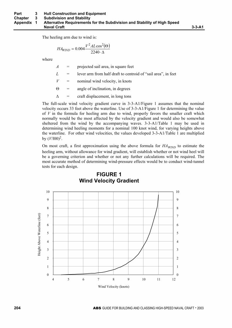
Part 3 Hull Construction and Equipment Chapter 3 Subdivision and Stability Appendix 1 Alternative Requirements for the Subdivision and Stability of High Speed
Naval Craft 3-3-A1
204 ABS GUIDE FOR BUILDING AND CLASSING HIGH-SPEED NAVAL CRAFT . 2003
The heeling arm due to wind is:
( )∆⋅Θ
=2240
cos004.022 ALVHAWIND
where
A = projected sail area, in square feet
L = lever arm from half draft to centroid of “sail area”, in feet
V = nominal wind velocity, in knots
Θ = angle of inclination, in degrees
∆ = craft displacement, in long tons
The full-scale wind velocity gradient curve in 3-3-A1/Figure 1 assumes that the nominal velocity occurs 33 feet above the waterline. Use of 3-3-A1/Figure 1 for determining the value of V in the formula for heeling arm due to wind, properly favors the smaller craft which normally would be the most affected by the velocity gradient and would also be somewhat sheltered from the wind by the accompanying waves. 3-3-A1/Table 1 may be used in determining wind heeling moments for a nominal 100 knot wind, for varying heights above the waterline. For other wind velocities, the values developed 3-3-A1/Table 1 are multiplied by (V/l00)2.
On most craft, a first approximation using the above formula for HAWIND to estimate the heeling arm, without allowance for wind gradient, will establish whether or not wind heel will be a governing criterion and whether or not any further calculations will be required. The most accurate method of determining wind-pressure effects would be to conduct wind-tunnel tests for each design.
FIGURE 1 Wind Velocity Gradient
4 5 6 7 8 9 10 11 120
1
2
3
4
5
6
7
8
9
10
0
1
2
3
4
5
6
7
8
9
10
Wind Velocity (knots)
Hei
ght A
bove
Wat
erlin
e (f
eet)
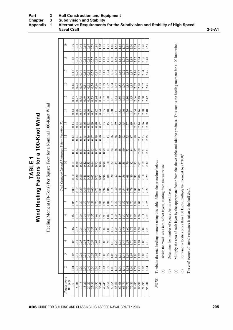
TAB
LE 1
W
ind
Hee
ling
Fact
ors
for a
100
-Kno
t Win
d
Hee
ling
Mom
ent (
Ft-T
ons)
Per
Squ
are
Foot
for a
Nom
inal
100
-Kno
t Win
d
C
raft
Cen
ter o
f Lat
eral
Res
ista
nce
Belo
w W
ater
line
(Ft)
Hei
ght a
bove
W
L (F
t) 2
3 4
5 6
7 8
9 10
11
12
13
14
15
16
17
18
19
0-5
0.04
0.
05
0.06
0.
07
0.07
0.
08
0.09
0.
10
0.11
0.
11
0.12
0.
13
0.14
0.
15
0.16
0.
17
0.18
0.
19
5-10
0.
11
0.12
0.
14
0.15
0.
16
0.18
0.
19
0.20
0.
20
0.22
0.
23
0.24
0.
26
0.27
0.
28
0.29
0.
31
0.32
10
-15
0.20
0.
21
0.23
0.
24
0.26
0.
27
0.29
0.
30
0.32
0.
33
0.34
0.
35
0.37
0.
38
0.40
0.
41
0.43
0.
44
15-2
0 0.
30
0.32
0.
33
0.34
0.
36
0.37
0.
39
0.41
0.
42
0.44
0.
45
0.46
0.
48
0.49
0.
51
0.53
0.
54
0.56
20
-25
0.40
0.
41
0.43
0.
45
0.46
0.
47
0.49
0.
51
0.53
0.
54
0.56
0.
58
0.60
0.
60
0.62
0.
64
0.66
0.
67
25-3
0 0.
50
0.52
0.
54
0.55
0.
57
0.59
0.
60
0.62
0.
64
0.65
0.
67
0.69
0.
71
0.73
0.
74
0.75
0.
77
0.79
30
-35
0.61
0.
62
0.64
0.
66
0.68
0.
70
0.72
0.
73
0.75
0.
77
0.79
0.
80
0.82
0.
84
0.86
0.
87
0.89
0.
91
35-4
0 0.
72
0.73
0.
75
0.77
0.
79
0.81
0.
83
0.85
0.
86
0.88
0.
90
0.92
0.
94
0.96
0.
98
1.00
1.
01
1.03
40
-45
0.83
0.
85
0.86
0.
88
0.90
0.
92
0.94
0.
96
0.98
0.
99
1.01
1.
03
1.05
1.
07
1.09
1.
11
1.13
1.
15
45-5
0 0.
95
0.97
0.
98
1.00
1.
02
1.04
1.
06
1.08
1.
10
1.12
1.
13
1.15
1.
18
1.20
1.
22
1.24
1.
26
1.27
50
-55
1.06
1.
08
1.10
1.
12
1.14
1.
16
1.18
1.
20
1.22
1.
24
1.26
1.
27
1.30
1.
31
1.34
1.
36
1.38
1.
40
55-6
0 1.
18
1.20
1.
22
1.24
1.
26
1.27
1.
30
1.32
1.
34
1.36
1.
38
1.39
1.
41
1.43
1.
46
1.48
1.
50
1.52
60
-65
1.30
1.
32
1.34
1.
36
1.38
1.
39
1.41
1.
44
1.46
1.
48
1.50
1.
52
1.53
1.
56
1.58
1.
60
1.62
1.
64
65-7
0 1.
41
1.44
1.
46
1.48
1.
50
1.52
1.
54
1.56
1.
58
1.60
1.
62
1.65
1.
66
1.68
1.
70
1.72
1.
75
1.77
70
-75
1.54
1.
56
1.58
1.
60
1.62
1.
65
1.66
1.
68
1.70
1.
73
1.75
1.
77
1.79
1.
80
1.83
1.
85
1.87
1.
89
75-8
0 1.
66
1.67
1.
70
1.72
1.
74
1.76
1.
79
1.80
1.
82
1.84
1.
87
1.89
1.
91
1.93
1.
95
1.97
1.
99
2.01
80
-85
1.79
1.
80
1.82
1.
84
1.87
1.
89
1.91
1.
93
1.95
1.
97
1.99
2.
02
2.04
2.
06
2.07
2.
10
2.12
2.
14
85-9
0 1.
91
1.92
1.
94
1.92
1.
99
2.01
2.
03
2.06
2.
07
2.09
2.
11
2.14
2.
16
2.18
2.
20
2.22
2.
24
2.28
90
-95
2.02
2.
05
2.06
2.
08
2.11
2.
13
2.15
2.
18
2.19
2.
21
2.23
2.
26
2.28
2.
30
2.32
2.
34
2.36
2.
40
95-1
00
2.14
2.
17
2.18
2.
20
2.23
2.
25
2.27
2.
29
2.32
2.
33
2.35
2.
38
2.40
2.
42
2.45
2.
46
2.48
2.
51
NO
TE:
To
obta
in th
e to
tal h
eelin
g m
omen
t usi
ng th
is ta
ble,
follo
w th
e pr
oced
ure
belo
w:
(a)
Div
ide
the
“sai
l” a
rea
into
5-f
oot l
ayer
s, st
artin
g fr
om th
e w
ater
line.
(b)
Det
erm
ine
the
num
ber o
f squ
are
feet
in e
ach
laye
r.
(c)
Mul
tiply
the
area
of e
ach
laye
r by
the
appr
opria
te fa
ctor
from
the
abov
e ta
ble
and
add
the
prod
ucts
. Th
is su
m is
the
heel
ing
mom
ent f
or a
100
kno
t win
d.
(d)
For w
ind
velo
citie
s oth
er th
an 1
00 k
nots
, mul
tiply
the
mom
ent b
y (V
/100
)2
The
craf
t cen
ter o
f lat
eral
resi
stan
ce is
take
n at
the
half
draf
t.
Part 3 Hull Construction and Equipment Chapter 3 Subdivision and Stability Appendix 1 Alternative Requirements for the Subdivision and Stability of High Speed
Naval Craft 3-3-A1
ABS GUIDE FOR BUILDING AND CLASSING HIGH-SPEED NAVAL CRAFT . 2003 205

Part 3 Hull Construction and Equipment Chapter 3 Subdivision and Stability Appendix 1 Alternative Requirements for the Subdivision and Stability of High Speed
Naval Craft 3-3-A1
206 ABS GUIDE FOR BUILDING AND CLASSING HIGH-SPEED NAVAL CRAFT . 2003
1.3.4 Criteria for Adequate Stability The criteria for adequate stability under adverse wind conditions are based on a comparison of the craft’s righting arm curve and the wind heeling arm curve, as illustrated in 3-3-A1/Figure 2, where the range of the righting arm curve terminates at the angle of unrestricted down flooding. If analysis shows that the craft can survive this flooding, a composite righting arm may be used. The “points” and “areas” referred to below are those depicted in 3-3-A1/Figure 2. Stability is considered to be satisfactory if:
1.3.4(a) The heeling arm at the intersection of the righting arm and heeling arm curves, Θ equilibrium or Point C, is not greater than six-tenths of the maximum righting arm:
HAEQUIL ≤ 0.6 ⋅ RAMAX
A wind heeling arm in excess of the craft’s righting arm would cause the craft to capsize. The requirement that the heeling arm be not greater than six-tenths of the maximum righting arm is intended to provide a margin for gusts.
1.3.4(b) Area A1 is not less than 1.4 A2, where Area A2 extends either 25 degrees or ΘR (if roll angle determined from model tests) to windward from Point C:
1.40 ⋅ A2 ≥ A1
In the second criterion, the craft is assumed to be heeled over by the wind to Point C and rolling 25 degrees or ΘR from this point to windward, where 25 degrees is a reasonable roll amplitude for heavy wind and sea conditions. Area A2 is a measure of the energy imparted to the craft by the wind and the craft's righting arm in returning to point C. The margin of 40% in A1 is intended to account for gusts and waves.
FIGURE 2 Intact Stability – Beam Winds with Rolling
RAMAX
ΘR
HAEQUIL
= A1 Area
= A2 Area
Point C
Maximum Righting Arm
Righting Arm
-20 -10 0 10 20 30 40 50 60 70 80
0
1
2
3
4
5
6
7
-1
-2
-3
-4
-5
Heeling Arm
Heel Angle (degrees)
Rig
htin
g an
d H
eelin
g A
rms (
feet
)

Part 3 Hull Construction and Equipment Chapter 3 Subdivision and Stability Appendix 1 Alternative Requirements for the Subdivision and Stability of High Speed
Naval Craft 3-3-A1
ABS GUIDE FOR BUILDING AND CLASSING HIGH-SPEED NAVAL CRAFT . 2003 207
1.5 Lifting of Heavy Weights over the Side
1.5.1 Effects of Lifting Weights Lifting of weights will be a governing factor in required stability only on craft which are used to lift heavy items over the side. Lifting of weights has a double effect upon transverse stability. The first effect is that the added weight, which acts at the upper end of the boom, will raise the craft’s center of gravity and thereby reduce the righting arm. The second effect is the heel caused by the transverse moment when lifting a weight over the side.
1.5.2 Heeling Arms For the purpose of applying the criteria, the craft’s righting arm curve is modified by correcting VCG and displacement to show the effect of the added weight at the end of the boom. The heeling arm curve is calculated as follows:
∆Θ
=)cos(WaHALIFT
where
W = weight of lift (tons)
a = transverse distance from centerline to end of boom (feet)
Θ = angle of inclination (degrees)
∆ = displacement plus the weight of lift (tons)
1.5.3 Criteria for Adequate Stability The criteria for adequate stability when lifting weights over the side are based on a comparison of the righting arm and heeling arm curves as illustrated in 3-3-A1/Figure 3. Stability is considered satisfactory if:
1.5.3(a) The limiting angle of heel (as indicated by Point C) shall not exceed 15 degrees or the angle at which one-half the freeboard submerges, whichever angle is smaller. A continuous heel angle of 15 degrees is the maximum acceptable from the standpoint of personnel safety.
ΘEQUIL ≤ 15 degrees or 1/2 freeboard
1.5.3(b) The heeling arm at the intersection of the righting arm and heeling arm curves, Θ equilibrium or Point C, is not more than six-tenths of the maximum righting arm:
HAEQUIL ≤ 0.6 ⋅ RAMAX
This provides a margin against capsizing.
1.5.3(c) The reserve of dynamic stability (Area A1) is not less than four-tenths of the total area, A0, under the righting arm curve.
0.4 ⋅ A0 ≤ A1
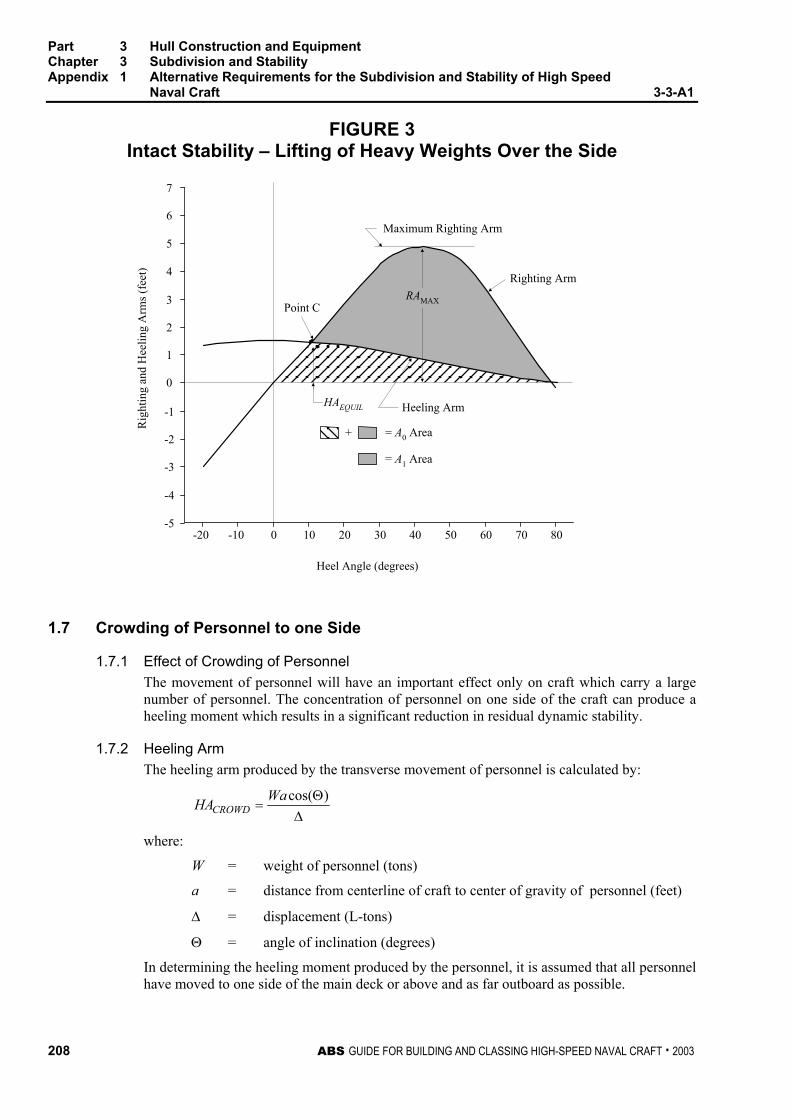
Part 3 Hull Construction and Equipment Chapter 3 Subdivision and Stability Appendix 1 Alternative Requirements for the Subdivision and Stability of High Speed
Naval Craft 3-3-A1
208 ABS GUIDE FOR BUILDING AND CLASSING HIGH-SPEED NAVAL CRAFT . 2003
FIGURE 3 Intact Stability – Lifting of Heavy Weights Over the Side
-20 -10 0 10 20 30 40 50 60 70 80
0
1
2
3
4
5
6
7
-1
-2
-3
-4
-5
RAMAX
Maximum Righting Arm
Righting Arm
HAEQUIL Heeling Arm
Point C
= A1 Area
= A0 Area+
Heel Angle (degrees)
Rig
htin
g an
d H
eelin
g A
rms (
feet
)
1.7 Crowding of Personnel to one Side
1.7.1 Effect of Crowding of Personnel The movement of personnel will have an important effect only on craft which carry a large number of personnel. The concentration of personnel on one side of the craft can produce a heeling moment which results in a significant reduction in residual dynamic stability.
1.7.2 Heeling Arm The heeling arm produced by the transverse movement of personnel is calculated by:
∆Θ
=)cos(WaHACROWD
where:
W = weight of personnel (tons)
a = distance from centerline of craft to center of gravity of personnel (feet)
∆ = displacement (L-tons)
Θ = angle of inclination (degrees)
In determining the heeling moment produced by the personnel, it is assumed that all personnel have moved to one side of the main deck or above and as far outboard as possible.

Part 3 Hull Construction and Equipment Chapter 3 Subdivision and Stability Appendix 1 Alternative Requirements for the Subdivision and Stability of High Speed
Naval Craft 3-3-A1
ABS GUIDE FOR BUILDING AND CLASSING HIGH-SPEED NAVAL CRAFT . 2003 209
1.7.3 Criteria for Adequate Stability The criteria for adequate stability are based on the angle of heel, and a comparison of the craft’s righting arm and the heeling arm curves, as illustrated in 3-3-A1/Figure 4. Stability is considered to be satisfactory if:
1.7.3(a) The angle of heel, as indicated by Point C, does not exceed 15 degrees. An angle of heel of 15 degrees is considered to be the maximum acceptable from the standpoint of personnel safety.
ΘEQUIL ≤ 15 degrees
1.7.3(b) The heeling arm at the intersection of the righting arm and heeling arm curves, Θ equilibrium or Point C, is not more than six-tenths of the maximum righting arm.
HAEQUIL ≤ 0.6 ⋅ RAMAX
1.7.3(c) The reserve of dynamic stability (Area A1) is not less than four-tenths of the total area, A0, under the righting arm curve.
0.4 ⋅ A0 ≤ A1
The requirements that the heeling arm be not more than six-tenths of the righting arm and that the reserve of dynamic stability be not less than four-tenths of the total area under the righting arm curve are intended to provide a margin against capsizing.
FIGURE 4 Intact Stability – The Effect of Crowding of Personnel to One Side
-20 -10 0 10 20 30 40 50 60 70 80
0
1
2
3
4
5
6
7
-1
-2
-3
-4
-5
RAMAX
Maximum Righting Arm
Righting Arm
HAEQUIL Heeling Arm
Point C
= A1 Area
= A0 Area+
Heel Angle (degrees)
Rig
htin
g an
d H
eelin
g A
rms (
feet
)
Part 3 Hull Construction and Equipment Chapter 3 Subdivision and Stability Appendix 1 Alternative Requirements for the Subdivision and Stability of High Speed
Naval Craft 3-3-A1
210 ABS GUIDE FOR BUILDING AND CLASSING HIGH-SPEED NAVAL CRAFT . 2003
1.9 High-Speed Turns
1.9.1 Effect of High-Speed Turns Heel in a high-speed turn may be a governing factor in required stability on highly maneuverable craft. The heel towards the outside of the turn is affected by the velocity in the turn and the turning radius associated with that velocity. The maximum heel may be associated with rudder angles less than full rudder due to the decreased speed in the tightest turns. The stability may differ due to the direction of the turn because most high-speed craft respond differently depending on the direction of the rudder and propeller thrusts at the higher speeds and rudder angles.
1.9.2 Heeling Arms The centrifugal force acting on a craft during a turn may be expressed by the formula:
gRvForce lCentrifuga
2∆=
where
∆ = displacement of craft (L-tons)
v = steady-state velocity of craft in the turn (ft/sec)
g = acceleration due to gravity (32.2 ft/sec2)
R = radius of turning circle (ft), normally one-half the tactical diameter
The lever arm used, in conjunction with this force, to obtain the heeling moment is the vertical distance between the craft’s center of gravity and the center of lateral resistance of the underwater body, adjusted for the angle of inclination. The center of lateral resistance may be assumed to be at the half-draft. If the centrifugal force is multiplied by the lever arm and divided by the craft’s displacement, the following expression for heeling arm is obtained:
gRavHAHSTURN
)cos(2 Θ=
where
a = distance between craft’s center of gravity and center of lateral resistance with craft upright (ft)
Θ = angle of inclination (degrees)
v, g and R are as defined in 3-3-A1/1.11.2.
1.9.3 Criteria for Adequate Stability The criteria for adequate stability in high-speed turns are based on the relationship between the righting arm curve and the heeling arm curve, as illustrated in 3-3-A1/Figure 5. Referring to this figure, stability is considered to be satisfactory if:
1.9.3(a) The angle of steady heel, as indicated by Point C, does not exceed 15 degrees. An angle of heel of 15 degrees is considered to be the maximum acceptable from the standpoint of personnel safety.
ΘEQUIL ≤ 15 degrees

Part 3 Hull Construction and Equipment Chapter 3 Subdivision and Stability Appendix 1 Alternative Requirements for the Subdivision and Stability of High Speed
Naval Craft 3-3-A1
ABS GUIDE FOR BUILDING AND CLASSING HIGH-SPEED NAVAL CRAFT . 2003 211
1.9.3(b) The heeling arm at the intersection of the righting arm and heeling-arm curves, Θ equilibrium or Point C, is not more than six-tenths of the maximum righting arm.
HAEQUIL ≤ 0.6 ⋅ RAMAX 1.9.3(c) The reserve of dynamic stability (Area A1) is not less than four-tenths of the total area, A0, under the righting arm curve.
0.4 ⋅ A0 ≤ A1 The requirements that the heeling arm be not more than six-tenths of the maximum righting arm and that the reserve of dynamic stability be not less than four-tenths of the total area under the righting arm curve are intended to provide a margin against capsizing.
FIGURE 5 Intact Stability – The Effect of Heel in a High Speed Turn
-20 -10 0 10 20 30 40 50 60 70 80
0
1
2
3
4
5
6
7
-1
-2
-3
-4
-5
RAMAX
Maximum Righting Arm
Righting Arm
HAEQUIL Heeling Arm
Point C
= A1 Area
= A0 Area+
Heel Angle (degrees)
Rig
htin
g an
d H
eelin
g A
rms (
feet
)
1.11 Topside Icing
1.11.1 Effects of Topside Icing The primary effect of topside icing is to raise the center of gravity of the craft; in addition, “unevenly distributed” topside ice will result in heel and trim angle. The criteria for adequate stability under adverse wind and topside icing are based on a comparison of the craft’s righting arm curve and the wind heeling arm curve for the craft in the minimum operating load condition with appropriate water ballast tanks full. The ballast tanks which shall be filled in the icing condition are those which can be filled without causing excessive trim by the bow, when the craft is severely iced. This will normally allow only for the after water ballast tanks to be filled.

Part 3 Hull Construction and Equipment Chapter 3 Subdivision and Stability Appendix 1 Alternative Requirements for the Subdivision and Stability of High Speed
Naval Craft 3-3-A1
212 ABS GUIDE FOR BUILDING AND CLASSING HIGH-SPEED NAVAL CRAFT . 2003
1.11.2 Heeling Arm When not specified by the Naval Administration, the assumed weight of ice is to be 10 percent of the craft’s displacement. The majority of ice build-up is likely to occur on the forecastle deck and arises from wind-blown spray. It is generally accepted that ice build-up occurs over the forward one-third of the overall length of the craft. The center of gravity of the ice may be assumed to be located on the centerline one-third of the overall length forward of midships and 4 feet above the weather deck.
The wind velocity to be used is 45 knots or as defined by the geographic service area.
1.11.3 Criteria for Adequate Stability Stability is considered satisfactory if as defined in 3-3-A1/Figure 6:
1.11.3(a)
HAEQUIL ≤ 0.6 ⋅ RAMAX
1.11.3(b)
1.4 ⋅ A2 ≤ A1 (A2 being defined for an angle of 25 degrees)
FIGURE 6 Intact Stability – The Effects of Icing, Beam Winds and Rolling
ΘR
= A1 Area
= A2 Area
Point C
Righting Arm
-20 -10 0 10 20 30 40 50 60 70 80
0
1
2
3
4
5
6
7
-1
-2
-3
-4
-5
Heeling Arm
Heel Angle (degrees)
Rig
htin
g an
d H
eelin
g A
rms (
feet
)

Part 3 Hull Construction and Equipment Chapter 3 Subdivision and Stability Appendix 1 Alternative Requirements for the Subdivision and Stability of High Speed
Naval Craft 3-3-A1
ABS GUIDE FOR BUILDING AND CLASSING HIGH-SPEED NAVAL CRAFT . 2003 213
3 Damage Stability Standards
3.1 General The craft is assumed to be in a full-load condition, with all tanks full, for the shell-to-shell flooding case. If appropriate, flooding on one side is to be investigated in order to take heel into account, with tanks loaded in such a manner as to produce unsymmetrical flooding consistent with liquid loading instructions
3.3 Extent of Damage Craft greater than 30 m (100 ft) in length are to be capable of withstanding the flooding of any two adjacent main compartments. Craft between 30 m (100 ft) and 12 m (40 ft) in length are to be capable of withstanding the flooding of any single compartment. Lesser or greater extents of damage may be specified by the Naval Administration.
3.5 Damaged-craft Stability Curves Curve A, in 3-3-A1/Figure 8, is a representative righting arm curve for the damaged craft. A reduction of righting arm equal to 0.05 ⋅ cosine(Θ) is included in Curve A to account for unknown unsymmetrical flooding and transverse shift of loose material.
Curve B, in 3-3-A1/Figure 8, is a beam-wind heeling arm curve which has been calculated by the method outlined in 3-3-A1/1.3.3 “Wind Heeling Arm”. In a damaged condition, it is to be assumed that the craft experiences a wind of lesser velocity than in the intact condition. The wind velocity used to develop Curve B is obtained from 3-3-A1/1.3.3. The analysis of adequate stability, thereafter is the same as in the intact case.
3.7 Criteria for Adequate Damaged-craft Stability The criteria for adequate stability are based on a comparison of the craft’s righting arm and heeling arm curves, as illustrated in 3-3-A1/Figure 8. The range of the righting arm curve terminates at the angle of unrestricted down flooding or 45 degrees, whichever occurs first. The following criteria are to be satisfied:
i) Damaged-craft stability is satisfactory if the initial angle of heel after damage, (Point D, 3-3-A1/Figure 8), does not exceed 15 degrees. An angle of heel of 15 degrees is considered to be the maximum acceptable from the standpoint of personnel safety.
ΘSTATIC ≤ 15 degrees
ii) The dynamic stability available to absorb the energy imparted to the craft by moderately rough seas in combination with beam winds is a measure of adequacy of the stability after damage. The reserve of dynamic stability (Area A1) shall not be less than 1.40 times the energy imparted to the craft by rough seas and beam winds (Area A2). The ΘR value used in the calculation shall be based on experience and model testing, or from 3-3-A1/Figure 7.
1.40 ⋅ A2 ≤ A1
iii) Area A1 is not less than the amount specified by the Naval Administration.
iv) The value of the maximum righting arm minus the value of the wind heeling arm at the same angle of heel shall be greater than 0.25 feet.
0.25 feet ≤ RAMAX – HA
v) After damage, the trim and heel angles at the equilibrium position shall not submerge the margin line.
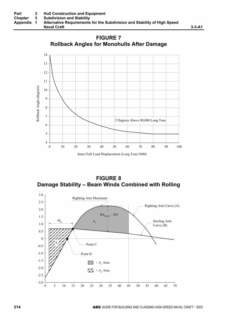
Part 3 Hull Construction and Equipment Chapter 3 Subdivision and Stability Appendix 1 Alternative Requirements for the Subdivision and Stability of High Speed
Naval Craft 3-3-A1
214 ABS GUIDE FOR BUILDING AND CLASSING HIGH-SPEED NAVAL CRAFT . 2003
FIGURE 7 Rollback Angles for Monohulls After Damage
5 Degrees Above 80,000 Long Tons
Intact Full Load Displacement (Long Tons/1000)
Rol
lbac
k A
ngle
(deg
rees
)
0 10 20 30 40 50 60 70 80 90 1004
5
6
7
8
9
10
11
12
13
14
FIGURE 8 Damage Stability – Beam Winds Combined with Rolling
A2
A1
RAMAX – HA
Righting Arm Maximum
ΘR
= A1 Area
= A2 Area
Point D
Point C
0 5 10 15 20 25 30 35 40 45 50 55 60 65 70-3.0
-2.5
-2.0
-1.5
-1.0
-0.5
0
0.5
1.0
1.5
2.0
2.5
3.0
Righting Arm Curve (A)
Heeling ArmCurve (B)

ABS GUIDE FOR BUILDING AND CLASSING HIGH-SPEED NAVAL CRAFT . 2003 215
P A R T
3 C H A P T E R 3 Subdivision and Stability
A P P E N D I X 2 Onboard Computers for Stability Calculations (1 July 2005)
1 General
1.1 Scope
The scope of stability calculation software is to be in accordance with the stability information as approved by the Naval Administration or the Bureau on behalf of the Naval Administration. The software is at least to include all information and perform all calculations or checks as necessary to ensure compliance with the applicable stability requirements.
Approved stability software is not a substitute for the approved stability information, and is used as a supplement to the approved stability information to facilitate stability calculations.
1.3 Design
The input/output information is to be easily comparable with approved stability information so as to avoid confusion and possible misinterpretation by the operator relative to the approved stability information.
An operation manual is to be provided for the onboard computer stability software.
The language in which the stability information is displayed and printed out as well as the operation manual is written is to be the same as used in the craft’s approved stability information. The primary language is to be English.
The onboard computer for stability calculations is craft specific equipment and the results of the calculations are only applicable to the craft for which it has been approved.
In case of modifications implying changes in the main data or internal arrangement of the craft, the specific approval of any original stability calculation software is no longer valid. The software is to be modified accordingly and reapproved.
3 Calculation Systems
This Appendix covers either system, a passive system that requires manual data entry or an active system, which replaces the manual with the automatic entry with sensors reading and entering the contents of tanks, etc., provided the active system is in the off-line operation mode. However, an integrated system, which controls or initiates actions based on the sensor-supplied inputs is not within the scope of this Appendix.

Part 3 Hull Construction and Equipment Chapter 3 Subdivision and Stability Appendix 3 Onboard Computers for Stability Calculations 3-3-A2
216 ABS GUIDE FOR BUILDING AND CLASSING HIGH-SPEED NAVAL CRAFT . 2003
5 Types of Stability Software
Three types of calculations performed by stability software are acceptable depending upon a craft’s stability requirements:
• Type 1 Software calculating intact stability only (for craft not required to meet a damage stability criterion)
• Type 2 Software calculating intact stability and checking damage stability on basis of a limit curve or previously approved loading conditions
• Type 3 Software calculating intact stability and damage stability by direct application of preprogrammed damage cases for each loading condition
7 Functional Requirements
7.1 Calculation Program The calculation program is to present relevant parameters of each loading condition in order to assist the Master in his judgment on whether the craft is loaded within the approval limits. The following parameters are to be presented for a given loading condition:
• Deadweight data
• Lightship data
• Trim
• Draft at the draft marks and perpendiculars
• Summary of loading condition displacement, VCG, LCG and, if applicable, TCG
• Downflooding angle and corresponding downflooding opening
• Compliance with stability criteria: Listing of all calculated stability criteria, the limit values, the obtained values and the conclusions (criteria fulfilled or not fulfilled)
7.3 Direct Damage Stability Calculations If direct damage stability calculations are performed, the relevant damage cases according to the applicable rules are to be pre-defined for automatic check of a given loading condition.
7.5 Warning A clear warning is to be given on screen and in hard copy printout if any of the loading limitations are not complied with.
7.7 Data Printout The data are to be presented on screen and in hard copy printout in a clear unambiguous manner.
7.9 Date and Time The date and time of a saved calculation are to be part of the screen display and hard copy printout.

Part 3 Hull Construction and Equipment Chapter 3 Subdivision and Stability Appendix 3 Onboard Computers for Stability Calculations 3-3-A2
ABS GUIDE FOR BUILDING AND CLASSING HIGH-SPEED NAVAL CRAFT . 2003 217
7.11 Information of Program Each hard copy printout is to include identification of the calculation program with version number.
7.13 Units Units of measurement are to be clearly identified and used consistently within a loading calculation.
9 Acceptable Tolerances
Depending on the type and scope of programs, the acceptable tolerances are to be determined differently, according to 3-3-A2/9.1 or 3-3-A2/9.3. In general, deviation from these tolerances is not to be accepted unless a satisfactory explanation for the difference is submitted for review and the same is satisfactorily confirmed by the Bureau that there would be no adverse effect on the safety of the craft.
Examples of pre-programmed input data include the following:
• Hydrostatic data: Displacement, LCB, LCF, VCB, KMt and MCT vs. draft
• Stability data: KN or MS values at appropriate heel/trim angles vs. displacement, stability limits.
• Compartment data: Volume, LCG, VCG, TCG and FSM heeling moments vs. level of the compartment’s contents.
Examples of output data include the following:
• Hydrostatic data: Displacement, LCB, LCF, VCB, KMt and MCT versus draft, as well as actual drafts, trim.
• Stability data: FSC (free surface correction), GZ-values, KG, GM, KG/GM limits, derived stability criteria (e.g., areas under the GZ curve), weather criteria.
• Compartment data: Calculated Volume, LCG, VCG, TCG and FSM heeling moments vs. level of the compartment’s contents
The computational accuracy of the calculation program results is to be within the acceptable tolerances specified in 3-3-A2/9.1 or 3-3-A2/9.3, of the results using an independent program or the approved stability information with identical input.
9.1 Calculation Program of the Approved Stability Information Programs which use only pre-programmed data from the approved stability information as the basis for stability calculations are to have zero tolerances for the printouts of input data.
Output data tolerances are to be close to zero. However, small differences associated with calculation rounding or abridged input data are acceptable. Additionally differences associated with the use of hydrostatic and stability data for trims that differ from those in the approved stability information are acceptable subject to review by the Bureau.
9.3 Independent Program for Assessment of Stability Programs which use hull form models as their basis for stability calculations are to have tolerances for the printouts of basic calculated data established against either data from the approved stability information or data obtained using the approval authority’s model. Acceptable tolerances shall be in accordance with 3-3-A2/Table 1.
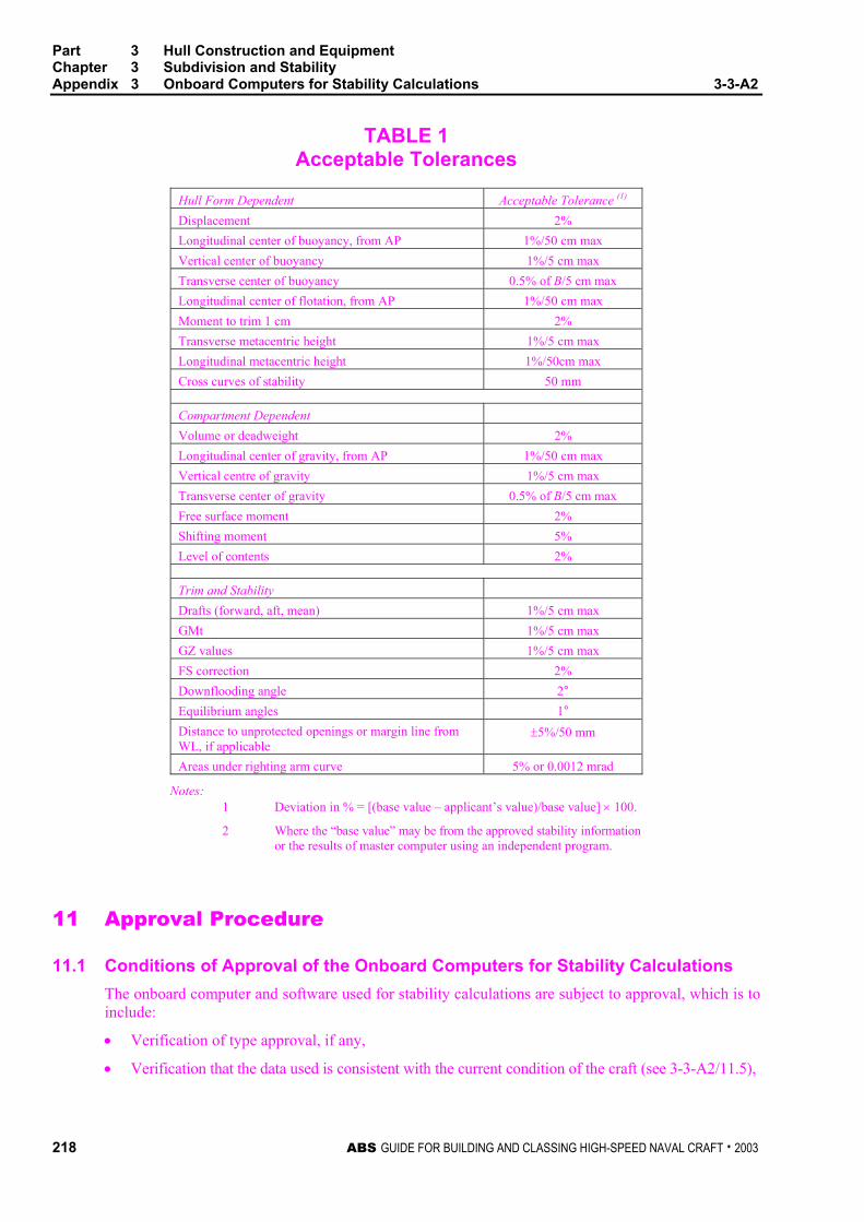
Part 3 Hull Construction and Equipment Chapter 3 Subdivision and Stability Appendix 3 Onboard Computers for Stability Calculations 3-3-A2
218 ABS GUIDE FOR BUILDING AND CLASSING HIGH-SPEED NAVAL CRAFT . 2003
TABLE 1 Acceptable Tolerances
Hull Form Dependent Acceptable Tolerance (1) Displacement 2% Longitudinal center of buoyancy, from AP 1%/50 cm max Vertical center of buoyancy 1%/5 cm max Transverse center of buoyancy 0.5% of B/5 cm max Longitudinal center of flotation, from AP 1%/50 cm max Moment to trim 1 cm 2% Transverse metacentric height 1%/5 cm max Longitudinal metacentric height 1%/50cm max Cross curves of stability 50 mm
Compartment Dependent Volume or deadweight 2% Longitudinal center of gravity, from AP 1%/50 cm max Vertical centre of gravity 1%/5 cm max Transverse center of gravity 0.5% of B/5 cm max Free surface moment 2% Shifting moment 5% Level of contents 2%
Trim and Stability Drafts (forward, aft, mean) 1%/5 cm max GMt 1%/5 cm max GZ values 1%/5 cm max FS correction 2% Downflooding angle 2° Equilibrium angles 1° Distance to unprotected openings or margin line from WL, if applicable
±5%/50 mm
Areas under righting arm curve 5% or 0.0012 mrad
Notes: 1 Deviation in % = [(base value – applicant’s value)/base value] × 100.
2 Where the “base value” may be from the approved stability information or the results of master computer using an independent program.
11 Approval Procedure
11.1 Conditions of Approval of the Onboard Computers for Stability Calculations The onboard computer and software used for stability calculations are subject to approval, which is to include:
• Verification of type approval, if any,
• Verification that the data used is consistent with the current condition of the craft (see 3-3-A2/11.5),

Part 3 Hull Construction and Equipment Chapter 3 Subdivision and Stability Appendix 3 Onboard Computers for Stability Calculations 3-3-A2
ABS GUIDE FOR BUILDING AND CLASSING HIGH-SPEED NAVAL CRAFT . 2003 219
• Verification and approval of the test conditions, and
• Verification that the software is appropriate for the type of craft and stability calculations required.
The satisfactory operation of the onboard computer(s) for stability calculations is to be verified by testing upon installation (see 3-3-A2/15). A copy of the approved test conditions and the operation manual for the computer/software are to be available onboard.
11.3 General Approval (optional) Upon receipt of application for general approval of the calculation program, the Bureau may provide the applicant with test data consisting of two or more design data sets, each of which is to include a craft’s hull form data, compartmentation data, lightship characteristics and deadweight data, in sufficient detail to accurately define the craft and its loading condition.
Acceptable hull form and compartmentation data may be in the form of surface coordinates for modeling the hull form and compartment boundaries (e.g., a table of offsets) or in the form of pre-calculated tabular data (e.g., hydrostatic tables, capacity tables) depending upon the form of data used by the software being submitted for approval. Alternatively, the general approval may be given based on at least two test craft agreed upon between the applicant and the Bureau.
In general, the software is to be tested for two types of craft for which approval is requested, with at least one design data set for each of the two types. Where approval is requested for only one type of craft, a minimum of two data sets for different hull forms of that type of craft are required to be tested.
For calculation software which is based on the input of hull form data, design data sets are to be provided for three types of craft for which the software is to be approved, or a minimum of three data sets for different hull forms if approval is requested for only one type of craft. Representative craft are those types which, due to their different hull forms, typical arrangements and nature of cargo, require different design data sets.
The test data sets are to be used by the applicant to run the calculation program for the test craft. The results obtained, together with the hydrostatic data and cross-curve data developed by the program, if appropriate are to be submitted to the Bureau for the assessment of the program’s computational accuracy. The Bureau is to perform parallel calculations using the same data sets and a comparison of these results will be made against the applicant’s submitted program’s results.
11.5 Specific Approval The Bureau is to verify the accuracy of the computational results and actual craft data used by the calculation program for the particular craft on which the program will be installed.
Upon receipt of application for data verification, the Bureau and the applicant are to agree on a minimum of four loading conditions, taken from the craft’s approved stability information, which are to be used as the test conditions.
For craft carrying liquids in bulk, at least one of the conditions is to include partially filled tanks. Within the test conditions each compartment is to be loaded at least once. The test conditions normally are to cover the range of load drafts from the deepest envisaged loaded condition to the light ballast condition and are to include at least one departure and one arrival condition.
The Bureau is to verify that the following data, submitted by the applicant, is consistent with arrangements and most recently approved lightship characteristics of the craft according to current plans and documentation on file with the Bureau, subject to possible further verification onboard:
• Identification of the calculation program including version number.
• Main dimensions, hydrostatic particulars and, if applicable, the craft profile.
• The position of the forward and after perpendiculars, and if appropriate, the calculation method to derive the forward and after drafts at the actual position of the craft’s draft marks.

Part 3 Hull Construction and Equipment Chapter 3 Subdivision and Stability Appendix 3 Onboard Computers for Stability Calculations 3-3-A2
220 ABS GUIDE FOR BUILDING AND CLASSING HIGH-SPEED NAVAL CRAFT . 2003
• Craft lightweight and center of gravity derived from the most recently approved inclining experiment or light weight check.
• Lines plan, offset tables or other suitable presentation of hull form data if necessary for the Bureau to model the craft.
• Compartment definitions, including frame spacing, and centers of volume, together with capacity tables (sounding/ullage tables), free surface corrections, if appropriate
• Cargo and Consumables distribution for each loading condition.
Verification by the Bureau does not absolve the applicant and craft owner of responsibility for ensuring that the information programmed into the onboard computer software is consistent with the current condition of the craft.
13 Operation Manual A simple and straightforward operation manual is to be provided, containing descriptions and instructions, as appropriate, for at least the following: • Installation • Function keys • Menu displays • Input and output data • Required minimum hardware to operate the software • Use of the test loading conditions • Computer-guided dialogue steps • List of warnings
15 Installation Testing To ensure correct working of the computer after the final or updated software has been installed, it is the responsibility of the craft’s master to have test calculations carried out according to the following pattern in the presence of the Surveyor:
• From the approved test conditions at least one load case (other than lightship) is to be calculated. Note: Actual loading condition results are not suitable for checking the correct working of the computer.
• Normally, the test conditions are permanently stored in the computer.
Steps to be performed:
• Retrieve the test load case and start a calculation run; compare the stability results with those in the documentation.
• Change several items of deadweight (tank weights and the cargo weight) sufficiently to change the draft or displacement by at least 10%. The results are to be reviewed to ensure that they differ in a logical way from those of the approved test condition.
• Revise the above modified load condition to restore the initial test condition and compare the results. The relevant input and output data of the approved test condition are to been replicated.
• Alternatively, one or more test conditions shall be selected and the test calculation performed by entering all deadweight data for each selected test condition into the program as if it were a proposed loading. The results shall be verified as identical to the results in the approved copy of the test conditions.

Part 3 Hull Construction and Equipment Chapter 3 Subdivision and Stability Appendix 3 Onboard Computers for Stability Calculations 3-3-A2
ABS GUIDE FOR BUILDING AND CLASSING HIGH-SPEED NAVAL CRAFT . 2003 221
17 Periodical Testing
It is the responsibility of the craft’s master to check the accuracy of the onboard computer for stability calculations at each Annual Survey by applying at least one approved test condition.
If the Surveyor is not present for the computer check, a copy of the test condition results obtained by the computer check is to be retained onboard as documentation of satisfactory testing for the Surveyor’s verification.
At each Special Periodical Survey, this checking for all approved test loading conditions is to be done in presence of the surveyor.
The testing procedure is to be carried out in accordance with 3-3-A2/15.
19 Other Requirements
The following features are to be provided to the software:
• Protection against unintentional or unauthorized modification of programs and data is to be provided.
• The program is to monitor operations and activate an alarm when the program is incorrectly or abnormally used.
• The program and any data stored in the system are to be protected from corruption by loss of power.
• Error messages with regard to limitations such as filling a compartment beyond capacity, or exceeding the assigned load line, etc. are to be included.

This Page Intentionally Left Blank

ABS GUIDE FOR BUILDING AND CLASSING HIGH-SPEED NAVAL CRAFT . 2003 223
P A R T
3 C H A P T E R 4 Fire Safety Measures
CONTENTS SECTION 1 Structural Fire Protection..................................................225
1 General ..............................................................................225 1.1 IMO High Speed Craft Code Application....................... 225 1.3 Other Craft .................................................................... 225
3 Review Procedures............................................................225 3.1 Administration Review................................................... 225 3.3 Bureau Review.............................................................. 225
5 The Review of Craft Constructed of Fiber Reinforced Plastic (FRP)......................................................................225

This Page Intentionally Left Blank
ABS GUIDE FOR BUILDING AND CLASSING HIGH-SPEED NAVAL CRAFT . 2003 225
P A R T
3 C H A P T E R 4 Fire Safety Measures
S E C T I O N 1 Structural Fire Protection
1 General
1.1 IMO High Speed Craft Code Application For classification purposes, the fire and safety measures contained in the IMO International Code of Safety for High Speed Craft – Chapter 7 for cargo craft are applicable to craft over 50 m (175 ft) in length, unless otherwise specified by the Naval Administration.
1.3 Other Craft For craft other than indicated above, the structural fire protection requirements are to be specified by the Naval Administration.
3 Review Procedures
3.1 Administration Review Where the Naval Administration undertakes any part of the review, for craft over 54 m (175 ft), their acceptance of the arrangements will be required to be submitted for classification.
3.3 Bureau Review In all other cases, the required information and plans are to be submitted to the Bureau for review.
5 The Review of Craft Constructed of Fiber Reinforced Plastic (FRP)
FRP fire-restricting divisions may be considered provided they meet the required tests for fire-restricting materials and fire-resisting divisions, or comply with an acceptable fire risk assessment. FRP divisions may also be considered on the basis of location with regard to diminished fire risk and enhanced fire detection/extinguishing means.

This Page Intentionally Left Blank

ABS GUIDE FOR BUILDING AND CLASSING HIGH-SPEED NAVAL CRAFT . 2003 227
P A R T
3 C H A P T E R 5 Equipment
CONTENTS SECTION 1 Anchoring and Mooring Equipment .................................229
1 General ..............................................................................229 3 Calculation of EN ...............................................................229
3.1 Monohulls...................................................................... 229 3.3 Multi-Hulled Craft .......................................................... 230
5 Equipment, Weight and Size .............................................231 5.1 Alternatives for Anchor Size.......................................... 231 5.3 Wire Rope ..................................................................... 231 5.5 Synthetic Fiber Rope..................................................... 232 5.7 Naval Administration Requirements .............................. 232
7 Materials and Tests............................................................232 9 Anchor Types.....................................................................232
9.1 General ......................................................................... 232 9.3 High Holding Power Anchors (HHP) ............................. 232 9.5 Super High Holding Power Anchors (SHHP) ................ 232
11 Windlass Support Structure and Cable Stopper................233 11.1 General ......................................................................... 233 11.3 Support Structure .......................................................... 233 11.5 Craft Less Than 54 m (175 ft) in Length........................ 237
13 Trial ....................................................................................237 15 Hawse Pipes ......................................................................237 TABLE 1 Equipment for Self-propelled Ocean-going Craft.....238 FIGURE 1a Effective Heights of Deck Houses – Monohulls .......230 FIGURE 1b Effective Heights of Deck Houses – Multi-Hulled
Craft .........................................................................231 FIGURE 2 Direction of Forces and Weight................................236 FIGURE 3 Sign Convention.......................................................236

228 ABS GUIDE FOR BUILDING AND CLASSING HIGH-SPEED NAVAL CRAFT . 2003
APPENDIX 1 Alternative Standard for the Required Anchor Size ....... 243 1 General ..............................................................................243 3 Anchor Size Requirement..................................................243 5 Anchor Chain, Cable, or Rope...........................................243
ABS GUIDE FOR BUILDING AND CLASSING HIGH-SPEED NAVAL CRAFT . 2003 229
P A R T
3 C H A P T E R 5 Equipment
S E C T I O N 1 Anchoring and Mooring Equipment
1 General
All craft are to have a complete equipment of anchor(s) and chains. The letter Á placed after the symbols of classification in the Record, thus: À A1 Á, will signify that the equipment of the craft is in compliance with the requirements of this Guide, and tested in accordance with 3-5-1/7, or with requirements, which have been specially approved for the particular service.
Cables which are intended to form part of the equipment are not to be used as deck chains when the craft is launched. The inboard ends of the cables of the bower anchors are to be secured by efficient means. Anchors and their cables are to be connected and positioned, ready for use. Where three anchors are given in 3-5-1/Table 1, the third anchor is intended as a spare anchor and is listed for guidance only; it is not required as a condition of classification. Means are to be provided for stopping each cable as it is paid out, and the windlass should be capable of heaving in either cable. Suitable arrangements are to be provided for securing the anchors and stowing the cables.
3 Calculation of EN
3.1 Monohulls The basic Equipment Number (EN) is to be obtained from the following equation for use in determining required equipment.
EN = k∆2/3 + m(Ba + Σbh) + nA
where
k = 1.0 (1.0, 1.012)
m = 2 (2, 0.186)
n = 0.1 (0.1, 0.00929)
∆ = molded displacement, in metric tons (long tons), at the summer load waterline.
B = molded breadth, as defined in 3-1-1/5, in m (ft)
h = h1, h2, h3, . . . as shown in 3-5-1/Figure 1a. In the calculation of h, sheer, camber and trim may be neglected.
a = freeboard, in m (ft), from the light waterline amidships.

Part 3 Hull Construction and Equipment Chapter 5 Equipment Section 1 Anchoring and Mooring Equipment 3-5-1
230 ABS GUIDE FOR BUILDING AND CLASSING HIGH-SPEED NAVAL CRAFT . 2003
h1, h2, h3… = height, in m (ft), on the centerline of each tier of houses having a breadth greater than B/4.
A = profile area, in m2 (ft2), of the hull, superstructure and houses above the summer load waterline which are within L (see 3-1-1/3). Superstructures or deckhouses having a breadth at any point no greater than 0.25B may be excluded. Screens and bulwarks more than 1.5 m (4.9 ft) in height are to be regarded as parts of houses when calculating h and A.
b = breadth, in m (ft), of the widest superstructure or deckhouse on each tier.
FIGURE 1a Effective Heights of Deck Houses – Monohulls
A B
3
2
1
a
h
h
h
B /8
3.3 Multi-Hulled Craft Anchors and chains are to be not less than given in 3-5-1/Table 1 and the numbers, weights and sizes of these are to be based on the equipment number obtained from the following equation. Special consideration will be given where anchoring and mooring conditions are specified.
Equipment Number = 2k3/2
2
∆ + m[(2Ba) + B1(a1 + Σh)] + nA
k, ∆, m, n and A are defined in 3-5-1/3.1.1.
B, B1, a, a1, h1, h2, h3, Σh are shown in 3-5-1/Figure 1b.
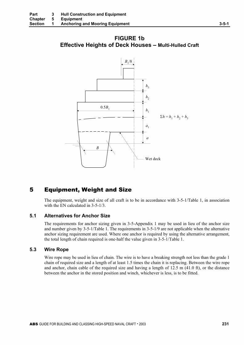
Part 3 Hull Construction and Equipment Chapter 5 Equipment Section 1 Anchoring and Mooring Equipment 3-5-1
ABS GUIDE FOR BUILDING AND CLASSING HIGH-SPEED NAVAL CRAFT . 2003 231
FIGURE 1b Effective Heights of Deck Houses – Multi-Hulled Craft
B1/8
0.5B1
B
h3
h2
h1
a1
a
Wet deck
Σh = h1 + h2 + h3
5 Equipment, Weight and Size
The equipment, weight and size of all craft is to be in accordance with 3-5-1/Table 1, in association with the EN calculated in 3-5-1/3.
5.1 Alternatives for Anchor Size The requirements for anchor sizing given in 3-5-Appendix 1 may be used in lieu of the anchor size and number given by 3-5-1/Table 1. The requirements in 3-5-1/9 are not applicable when the alternative anchor sizing requirement are used. Where one anchor is required by using the alternative arrangement, the total length of chain required is one-half the value given in 3-5-1/Table 1.
5.3 Wire Rope Wire rope may be used in lieu of chain. The wire is to have a breaking strength not less than the grade 1 chain of required size and a length of at least 1.5 times the chain it is replacing. Between the wire rope and anchor, chain cable of the required size and having a length of 12.5 m (41.0 ft), or the distance between the anchor in the stored position and winch, whichever is less, is to be fitted.

Part 3 Hull Construction and Equipment Chapter 5 Equipment Section 1 Anchoring and Mooring Equipment 3-5-1
232 ABS GUIDE FOR BUILDING AND CLASSING HIGH-SPEED NAVAL CRAFT . 2003
5.5 Synthetic Fiber Rope Synthetic fiber rope may be used in lieu of anchor chain cable provided the craft meets the following:
i) The craft is less than 54 m (175 ft) in length.
ii) A length of chain is to be fitted between the anchor and synthetic fiber line.
iii) The chain is not to be less than the required Grade 1 chain for the equipment number.
iv) The chain length is to be at least the distance between the windlass and the anchor in the stowed position and not less than 0.2L meters (feet).
v) The ropes are to be stowed on drums or lockers, protected from the weather and sea, and are to be lead over rollers.
vi) The rope length is to be at least 1.5 times the required chain length.
vii) The breaking strength of the rope is to be at least equal to the breaking strength of the required Grade 1 chain cable.
viii) Synthetic fiber ropes for this application are to be polymide fiber rope or equivalent. Polypropylene rope is not to be used.
ix) If the anchors are HHP or SHHP, the combined cable/synthetic rope is to be adequate for the verified holding power of the anchor.
5.7 Naval Administration Requirements Consideration will be given to anchor and chain weight and size specified by the Naval Administration based on the type and service of the craft. Justifications supporting the size and weight selection may be requested to be submitted for review.
7 Materials and Tests
Material and testing for anchors and chains on craft are to be in accordance with the requirements of Part 2, Chapter 2 for the respective sizes of anchors and chains. See Sections 2-2-1 and 2-2-2. Materials and tests for wire rope are to be in accordance with a national or other recognized standard.
9 Anchor Types
9.1 General Anchors are in general to be of the stockless type. The weight of the head of a stockless anchor. including pins and fittings, is not to be less than three-fifths of the total weight of the anchor.
9.3 High Holding Power Anchors (HHP) Where the anchor has a proven holding power of not less than two times that of an ordinary stockless anchor and has been tested in accordance with Section 2-2-1 a weight reduction of 25% from the weight specified in 3-5-1/Table 1 will be given. For HHP anchors an appropriate notation will be made in the Record.
9.5 Super High Holding Power Anchors (SHHP) Where the anchor has a proven holding power of not less than four times that of an ordinary stockless anchor and has been tested in accordance with Section 2-2-1 a weight reduction of 50% from the weight specified in 3-5-1/Table 1 will be given. For SHHP anchors an appropriate notation will be made in the Record.

Part 3 Hull Construction and Equipment Chapter 5 Equipment Section 1 Anchoring and Mooring Equipment 3-5-1
ABS GUIDE FOR BUILDING AND CLASSING HIGH-SPEED NAVAL CRAFT . 2003 233
11 Windlass Support Structure and Cable Stopper
11.1 General (1 January 2004) The windlass is to be of good and substantial make suitable for the size of intended anchor cable. The winch is to be well bolted down to a substantial bed, and deck beams below the windlass are to be of extra strength and additionally supported. Where wire ropes are used in lieu of chain cables, winches capable of controlling the wire rope at all times are to be fitted.
Construction and installation of all windlasses and winches used for anchoring are to be carried out in accordance with the following requirements, to the satisfaction of the Surveyor. In general, the design is to conform to an applicable standard or code of practice. As a minimum, standards or practices are to indicate strength, performance and testing criteria.
The windlass supporting structures are to meet the requirements in 3-5-1/11.3. Where the mooring winch is integral with the windlass, it is to be considered as a part of the windlass for the purpose of said paragraph.
The manufacturer or builder is to submit in accordance with 4-1-1/5, the following, as applicable:
11.1.1 Plans i) Arrangement and details of the windlass or winch, drums, brakes, shaft, gears, coupling
bolts, wildcat, sheaves, pulleys and foundation. ii) Electric one line diagram iii) Piping system diagrams iv) Control arrangements.
Plans or data are to show complete details including power ratings, working pressures, welding details, material specifications, pipe and electric cable specifications, etc.
11.1.2 Calculations Detailed stress calculations for the applicable system components listed in 3-5-1/11.1.1i) above. The calculations are to be based on the breaking strength of the chain or wire rope; are to indicate maximum torque or load to which the unit will be subjected and also show compliance with either applicable sections of the Rules, such as Section 4-3-1 and Appendix 4-3-1A1 for the gears and shafts, or to other recognized standard or code of practice.
11.3 Support Structure (1 January 2004) The windlass is to be bolted down to a substantial foundation, which is to meet the following load cases and associated criteria.
An independent cable stopper and its components are to be adequate for the load imposed. The arrangements and details of the cable stopper are to be submitted for review.
11.3.1 Operating Loads 11.3.1(a) Load on Windlass Support Structure (2006). The following load is to be applied in the direction of the chain.
With cable stopper not attached to windlass: 45% of B.S.
With cable stopper attached to windlass: 80% of B.S.
Without cable stopper: 80% of B.S.
B.S. = minimum breaking strength of the chain, as indicated in 2-2-2/Tables 2 and 3 of the Rules for Materials and Welding – Part 2.
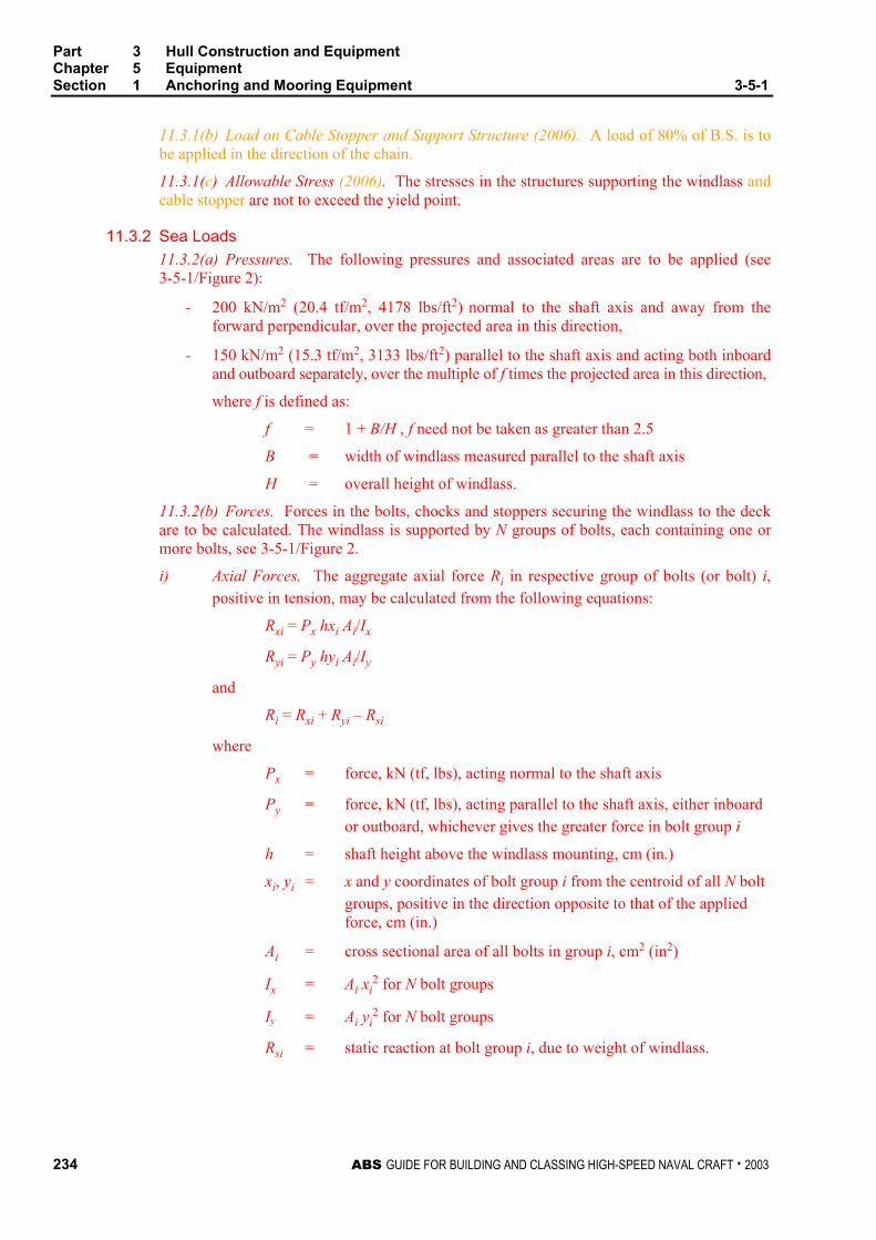
Part 3 Hull Construction and Equipment Chapter 5 Equipment Section 1 Anchoring and Mooring Equipment 3-5-1
234 ABS GUIDE FOR BUILDING AND CLASSING HIGH-SPEED NAVAL CRAFT . 2003
11.3.1(b) Load on Cable Stopper and Support Structure (2006). A load of 80% of B.S. is to be applied in the direction of the chain.
11.3.1(c) Allowable Stress (2006). The stresses in the structures supporting the windlass and cable stopper are not to exceed the yield point.
11.3.2 Sea Loads 11.3.2(a) Pressures. The following pressures and associated areas are to be applied (see 3-5-1/Figure 2):
- 200 kN/m2 (20.4 tf/m2, 4178 lbs/ft2) normal to the shaft axis and away from the forward perpendicular, over the projected area in this direction,
- 150 kN/m2 (15.3 tf/m2, 3133 lbs/ft2) parallel to the shaft axis and acting both inboard and outboard separately, over the multiple of f times the projected area in this direction,
where f is defined as:
f = 1 + B/H , f need not be taken as greater than 2.5
B = width of windlass measured parallel to the shaft axis
H = overall height of windlass.
11.3.2(b) Forces. Forces in the bolts, chocks and stoppers securing the windlass to the deck are to be calculated. The windlass is supported by N groups of bolts, each containing one or more bolts, see 3-5-1/Figure 2.
i) Axial Forces. The aggregate axial force Ri in respective group of bolts (or bolt) i, positive in tension, may be calculated from the following equations:
Rxi = Px hxi Ai/Ix
Ryi = Py hyi Ai/Iy
and
Ri = Rxi + Ryi – Rsi
where
Px = force, kN (tf, lbs), acting normal to the shaft axis
Py = force, kN (tf, lbs), acting parallel to the shaft axis, either inboard or outboard, whichever gives the greater force in bolt group i
h = shaft height above the windlass mounting, cm (in.)
xi, yi = x and y coordinates of bolt group i from the centroid of all N bolt groups, positive in the direction opposite to that of the applied force, cm (in.)
Ai = cross sectional area of all bolts in group i, cm2 (in2)
Ix = Ai xi2 for N bolt groups
Iy = Ai yi2 for N bolt groups
Rsi = static reaction at bolt group i, due to weight of windlass.
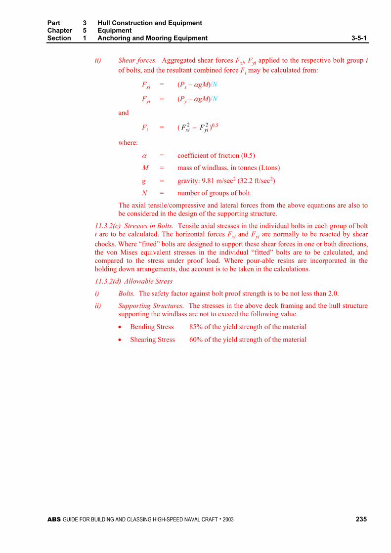
Part 3 Hull Construction and Equipment Chapter 5 Equipment Section 1 Anchoring and Mooring Equipment 3-5-1
ABS GUIDE FOR BUILDING AND CLASSING HIGH-SPEED NAVAL CRAFT . 2003 235
ii) Shear forces. Aggregated shear forces Fxi, Fyi applied to the respective bolt group i of bolts, and the resultant combined force Fi may be calculated from:
Fxi = (Px – αgM)/N
Fyi = (Py – αgM)/N
and
Fi = ( 2xiF – 2
yiF )0.5
where:
α = coefficient of friction (0.5)
M = mass of windlass, in tonnes (Ltons)
g = gravity: 9.81 m/sec2 (32.2 ft/sec2)
N = number of groups of bolt.
The axial tensile/compressive and lateral forces from the above equations are also to be considered in the design of the supporting structure.
11.3.2(c) Stresses in Bolts. Tensile axial stresses in the individual bolts in each group of bolt i are to be calculated. The horizontal forces Fxi and Fyi are normally to be reacted by shear chocks. Where “fitted” bolts are designed to support these shear forces in one or both directions, the von Mises equivalent stresses in the individual “fitted” bolts are to be calculated, and compared to the stress under proof load. Where pour-able resins are incorporated in the holding down arrangements, due account is to be taken in the calculations.
11.3.2(d) Allowable Stress
i) Bolts. The safety factor against bolt proof strength is to be not less than 2.0.
ii) Supporting Structures. The stresses in the above deck framing and the hull structure supporting the windlass are not to exceed the following value.
• Bending Stress 85% of the yield strength of the material
• Shearing Stress 60% of the yield strength of the material

Part 3 Hull Construction and Equipment Chapter 5 Equipment Section 1 Anchoring and Mooring Equipment 3-5-1
236 ABS GUIDE FOR BUILDING AND CLASSING HIGH-SPEED NAVAL CRAFT . 2003
FIGURE 2 Direction of Forces and Weight (2004)
Py
H
hW
Px
Fore
Px
PyCenterline of Vessel
Centerline ofWindlass
Note:Py to be examined from both inboard and outboarddirections separately - see 3-5-1/11.3.2(a). Thesign convention for yi is reversed when Py is fromthe opposite direction as shown.
B
FIGURE 3 Sign Convention (2004)
Centerline ofWindlass
Centroid of Bolt Groups
Px
Py
y3 (+ve)
y4 (+ve)
y2 (+ve)
y1 (+ve)
x1 (+ve)x2 (+ve)x4 (-ve)
x3 (-ve)
Coordinates xi and yi are shown as eitherpositive (+ve) or negative (-ve).

Part 3 Hull Construction and Equipment Chapter 5 Equipment Section 1 Anchoring and Mooring Equipment 3-5-1
ABS GUIDE FOR BUILDING AND CLASSING HIGH-SPEED NAVAL CRAFT . 2003 237
11.5 Craft Less Than 54 m (175 ft) in Length Where it is not practical to fit an anchor windlass or winch that has been approved by ABS in accordance with 3-5-1/11.1, consideration will be given to fitting an anchor windlass that is provided with a certificate from the manufacturer. This certificate is to state that the equipment has been designed to accommodate the breaking strength of the required chain or wire rope. If the required anchor weight is less than 38.5 kg (85 lbs) no winch or windlass is required.
13 Trial See 3-6-2/1.
15 Hawse Pipes Hawse pipes are to be of ample size and strength; they are to have full rounded flanges and the least possible lead, in order to minimize the nip on the cables; they are to be securely attached to thick doubling or insert plates by continuous welds the size of which are to be in accordance with Section 3/23 for the plating thickness and type of joint selected. When in position they are to be thoroughly tested for watertightness by means of a hose in which the water pressure is not to be less than 2.06 bar (2.1 kgf/cm2, 30 psi). Hawse pipes for stockless anchors are to provide ample clearances; the anchors are to be shipped and unshipped so that the Surveyor may be satisfied that there is no risk of the anchor jamming in the hawse pipe. Care is to be taken to ensure a fair lead for the chain from the windlass to the hawse pipes and to the chain pipes.
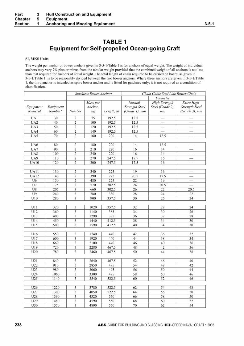
Part 3 Hull Construction and Equipment Chapter 5 Equipment Section 1 Anchoring and Mooring Equipment 3-5-1
238 ABS GUIDE FOR BUILDING AND CLASSING HIGH-SPEED NAVAL CRAFT . 2003
TABLE 1 Equipment for Self-propelled Ocean-going Craft
SI, MKS Units
The weight per anchor of bower anchors given in 3-5-1/Table 1 is for anchors of equal weight. The weight of individual anchors may vary 7% plus or minus from the tabular weight provided that the combined weight of all anchors is not less than that required for anchors of equal weight. The total length of chain required to be carried on board, as given in 3-5-1/Table 1, is to be reasonably divided between the two bower anchors. Where three anchors are given in 3-5-1/Table 1, the third anchor is intended as spare bower anchor and is listed for guidance only; it is not required as a condition of classification.
Stockless Bower Anchors Chain Cable Stud Link Bower Chain Diameter
Equipment Numeral
Equipment Number*
Number
Mass per Anchor,
kg
Length, m
Normal-Strength Steel (Grade 1), mm
High-Strength Steel (Grade 2),
mm
Extra High-Strength Steel (Grade 3), mm
UA1 30 2 75 192.5 12.5 — — UA2 40 2 100 192.5 12.5 — — UA3 50 2 120 192.5 12.5 — — UA4 60 2 140 192.5 12.5 — — UA5 70 2 160 220 14 12.5 —
UA6 80 2 180 220 14 12.5 — UA7 90 2 210 220 16 14 — UA8 100 2 240 220 16 14 — UA9 110 2 270 247.5 17.5 16 — UA10 120 2 300 247.5 17.5 16 —
UA11 130 2 340 275 19 16 — UA12 140 2 390 275 20.5 17.5 —
U6 150 2 480 275 22 19 — U7 175 2 570 302.5 24 20.5 — U8 205 3 660 302.5 26 22 20.5 U9 240 3 780 330 28 24 22 U10 280 3 900 357.5 30 26 24
U11 320 3 1020 357.5 32 28 24 U12 360 3 1140 385 34 30 26 U13 400 3 1290 385 36 32 28 U14 450 3 1440 412.5 38 34 30 U15 500 3 1590 412.5 40 34 30
U16 550 3 1740 440 42 36 32 U17 600 3 1920 440 44 38 34 U18 660 3 2100 440 46 40 36 U19 720 3 2280 467.5 48 42 36 U20 780 3 2460 467.5 50 44 38
U21 840 3 2640 467.5 52 46 40 U22 910 3 2850 495 54 48 42 U23 980 3 3060 495 56 50 44 U24 1060 3 3300 495 58 50 46 U25 1140 3 3540 522.5 60 52 46
U26 1220 3 3780 522.5 62 54 48 U27 1300 3 4050 522.5 64 56 50 U28 1390 3 4320 550 66 58 50 U29 1480 3 4590 550 68 60 52 U30 1570 3 4890 550 70 62 54

Part 3 Hull Construction and Equipment Chapter 5 Equipment Section 1 Anchoring and Mooring Equipment 3-5-1
ABS GUIDE FOR BUILDING AND CLASSING HIGH-SPEED NAVAL CRAFT . 2003 239
TABLE 1 (continued) SI, MKS Units
Stockless Bower Anchors Chain Cable Stud Link Bower Chain Diameter
Equipment Numeral
Equipment Number*
Number
Mass perAnchor,
kg
Length, m
Normal-Strength Steel (Grade 1), mm
High-Strength Steel (Grade 2),
mm
Extra High-Strength Steel (Grade 3), mm
U31 1670 3 5250 577.5 73 64 56 U32 1790 3 5610 577.5 76 66 58 U33 1930 3 6000 577.5 78 68 60 U34 2080 3 6450 605 81 70 62 U35 2230 3 6900 605 84 73 64
U36 2380 3 7350 605 87 76 66 U37 2530 3 7800 632.5 90 78 68 U38 2700 3 8300 632.5 92 81 70 U39 2870 3 8700 632.5 95 84 73 U40 3040 3 9300 660 97 84 76
U41 3210 3 9900 660 100 87 78 U42 3400 3 10500 600 102 90 78 U43 3600 3 11100 687.5 105 92 81 U44 3800 3 11700 687.5 107 95 84 U45 4000 3 12300 687.5 111 97 87
U46 4200 3 12900 715 114 100 87 U47 4400 3 13500 715 117 102 90 U48 4600 3 14100 715 120 105 92 U49 4800 3 14700 742.5 122 107 95 U50 5000 3 15400 742.5 124 111 97
U51 5200 3 16100 742.5 127 111 97 U52 5500 3 16900 742.5 130 114 100 U53 5800 3 17800 742.5 132 117 102 U54 6100 3 18800 742.5 120 107 U55 6500 3 20000 770 124 111
U56 6900 3 21500 770 127 114 U57 7400 3 23000 770 132 117 U58 7900 3 24500 770 137 122 U59 8400 3 26000 770 142 127 U60 8900 3 27500 770 147 132 U61 9400 3 29000 770 152 132
U62 10000 3 31000 770 137 U63 10700 3 33000 770 142 U64 11500 3 35500 770 147 U65 12400 3 38500 770 152 U66 13400 3 42000 770 157 U67 14600 3 46000 770 162
** For intermediate values of equipment number use equipment complement in sizes and weights given for the lower equipment number in the table.

Part 3 Hull Construction and Equipment Chapter 5 Equipment Section 1 Anchoring and Mooring Equipment 3-5-1
240 ABS GUIDE FOR BUILDING AND CLASSING HIGH-SPEED NAVAL CRAFT . 2003
TABLE 1 Equipment for Self-propelled Ocean-going Craft
US Units
The weight per anchor of bower anchors given in 3-5-1/Table 1 is for anchors of equal weight. The weight of individual anchors may vary 7% plus or minus from the tabular weight provided that the combined weight of all anchors is not less than that required for anchors of equal weight. The total length of chain required to be carried on board, as given in 3-5-1/Table 1, is to be reasonably divided between the two bower anchors. Where three anchors are given in 3-5-1/Table 1, the third anchor is intended as spare bower anchor and is listed for guidance only; it is not required as a condition of classification.
Stackless Bower Anchors Chain Cable Stud Link Bower Chain Diameter
Equipment Numeral
Equipment Number*
Number
Mass per Anchor, pounds
Length, fathoms
Normal-Strength Steel (Grade 1),
inches
High-Strength Steel (Grade 2),
inches
Extra High-Strength Steel
(Grade 3), inches
UA1 30 2 165 105 1/2 — — UA2 40 2 220 105 1/2 — — UA3 50 2 265 105 1/2 — — UA4 60 2 310 105 ½ — — UA5 70 2 350 120 9/16 1/2 —
UA6 80 2 400 120 9/16 1/2 — UA7 90 2 460 120 5/8 9/16 — UA8 100 2 530 120 5/8 9/16 — UA9 110 2 595 135 11/16 5/8 — UA10 120 2 670 135 11/16 5/8 —
UA11 130 2 750 150 3/4 11/16 — UA12 140 2 860 150 13/16 11/16 —
U6 150 2 1060 150 7/8 3/4 — U7 175 2 1255 165 15/16 13/16 — U8 205 3 1455 165 1 7/8 13/16 U9 240 3 1720 180 1 1/8 15/16 7/8 U10 280 3 1985 195 1 3/16 1 15/16
U11 320 3 2250 195 1 1/4 1 1/8 15/16 U12 360 3 2510 210 1 5/16 1 3/16 1 U13 400 3 2840 210 1 7/16 1 1/4 1 1/8 U14 450 3 3170 225 1 1/2 1 5/16 1 3/16 U15 500 3 3500 225 1 9/16 1 5/16 1 3/16
U16 550 3 3830 240 1 5/8 1 7/16 1 1/4 U17 600 3 4230 240 1 3/4 1 1/2 1 5/16 U18 660 3 4630 240 1 13/16 1 9/16 1 7/16 U19 720 3 5020 255 1 7/8 1 5/8 1 7/16 U20 780 3 5420 255 2 1 3/4 1 1/2
U21 840 3 5820 255 2 1/16 1 13/16 1 9/16 U22 910 3 6280 270 2 1/8 1 7/8 1 5/8 U23 980 3 6740 270 2 3/16 1 15/16 1 3/4 U24 1060 3 7270 270 2 5/16 2 1 13/16 U25 1140 3 7800 285 2 3/8 2 1/16 1 13/16
U26 1220 3 8330 285 2 7/16 2 1/8 1 7/8 U27 1300 3 8930 285 2 1/2 2 3/16 2 U28 1390 3 9520 300 2 5/8 2 5/16 2 U29 1480 3 10120 300 2 11/16 2 3/8 2 1/16 U30 1570 3 10800 300 2 3/4 2 7/16 2 1/8
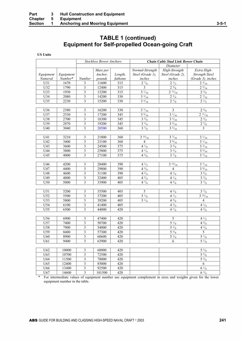
Part 3 Hull Construction and Equipment Chapter 5 Equipment Section 1 Anchoring and Mooring Equipment 3-5-1
ABS GUIDE FOR BUILDING AND CLASSING HIGH-SPEED NAVAL CRAFT . 2003 241
TABLE 1 (continued) Equipment for Self-propelled Ocean-going Craft
US Units
Stockless Bower Anchors Chain Cable Stud Link Bower Chain Diameter
Equipment Numeral
EquipmentNumber*
Number
Mass perAnchor,pounds
Length, fathoms
Normal-Strength Steel (Grade 1),
inches
High-Strength Steel (Grade 2),
inches
Extra High-Strength Steel
(Grade 3), inches U31 1670 3 11600 315 2 7/8 2 1/2 2 3/16 U32 1790 3 12400 315 3 2 5/8 2 5/16 U33 1930 3 13200 315 3 1/16 2 11/16 2 3/8 U34 2080 3 14200 330 3 3/16 2 3/4 2 7/16 U35 2230 3 15200 330 3 5/16 2 7/8 2 1/2
U36 2380 3 16200 330 3 7/16 3 2 5/8 U37 2530 3 17200 345 3 9/16 3 1/16 2 11/16 U38 2700 3 18300 345 3 5/8 3 3/16 2 3/4 U39 2870 3 19200 345 3 3/4 3 5/16 2 7/8 U40 3040 3 20500 360 3 7/8 3 5/16 3
U41 3210 3 21800 360 3 15/16 3 7/16 3 1/16 U42 3400 3 23100 360 4 3 9/16 3 1/16 U43 3600 3 24500 375 4 1/8 3 5/8 3 3/16 U44 3800 3 25800 375 4 1/4 3 3/4 3 5/16 U45 4000 3 27100 375 4 3/8 3 7/8 3 7/16
U46 4200 3 28400 390 4 1/2 3 15/16 3 7/16 U47 4400 3 29800 390 4 5/8 4 3 9/16 U48 4600 3 31100 390 4 3/4 4 1/8 3 5/8 U49 4800 3 32400 405 4 3/4 4 1/4 3 3/4 U50 5000 3 33900 405 4 7/8 4 3/8 3 7/8
U51 5200 3 35500 405 5 4 3/8 3 7/8 U52 5500 3 37200 405 5 1/8 4 1/2 3 15/16 U53 5800 3 39200 405 5 1/8 4 5/8 4 U54 6100 3 41400 405 4 3/4 4 1/4 U55 6500 3 44000 420 4 7/8 4 3/8
U56 6900 3 47400 420 5 4 1/2 U57 7400 3 50700 420 5 1/8 4 5/8 U58 7900 3 54000 420 5 3/8 4 3/4 U59 8400 3 57300 420 5 5/8 5 U60 8900 3 60600 420 5 3/4 5 1/8 U61 9400 3 63900 420 6 5 1/8
U62 10000 3 68000 420 5 3/8 U63 10700 3 72500 420 5 5/8 U64 11500 3 78000 420 5 3/4 U65 12400 3 85000 420 6 U66 13400 3 92500 420 6 1/8 U67 14600 3 101500 420 6 3/8
** For intermediate values of equipment number use equipment complement in sizes and weights given for the lower equipment number in the table.

This Page Intentionally Left Blank
ABS GUIDE FOR BUILDING AND CLASSING HIGH-SPEED NAVAL CRAFT . 2003 243
P A R T
3 C H A P T E R 5 Equipment
A P P E N D I X 1 Alternative Standard for the Required Anchor Size
1 General
All craft are to have anchor and chain that comply with the requirements in Section 3-5-1 of this Guide or the requirements listed below. The letter Á will signify that the equipment of the craft is in compliance with the requirements in the Guide and tested in accordance with Section 3-5-1/9 of this Guide.
3 Anchor Size Requirement
A minimum of one (1) anchor is to be provided that has a holding power in a bottom that has an average consistency between mud and sand that is greater than determined by the following equation. The holding power of the anchor is to be certified by the anchor manufacturer.
HP = 0.0195AVw2 + 0.114 L∆ (Vc)1.825 + 7.74NpApVc
2 kg
HP = 0.004AVw2 + 0.14 L∆ (Vc)1.825 + 1.59NpApVc
2 lbf
where
HP = required holding power of anchor, in kg (lbf)
A = projected frontal area of the craft above the waterline, in m2 (ft2)
Vw = velocity of wind acting on the craft, not to be taken less than 50 knots
∆ = molded displacement of the craft, in mt (lbf), to the summer load line
L = length of craft, in m (ft), as defined in 3-1-1/1.1
Vc = velocity of current acting on the craft, not to be taken less than 3 knots
Np = number of propellers fitted on the craft
Ap = area of one propeller, in m2 (ft2)
5 Anchor Chain, Cable, or Rope
The required size and length of chain, cable, or rope is to be as indicated in 3-5-1. Where one anchor is allowed the required chain length is one half the length required from 3-5-1/Table 1.

This Page Intentionally Left Blank

ABS GUIDE FOR BUILDING AND CLASSING HIGH-SPEED NAVAL CRAFT . 2003 245
P A R T
3 C H A P T E R 6 Testing, Trials and Surveys During
Construction – Hull
CONTENTS SECTION 1 Tank, Bulkhead and Rudder Tightness Testing..............247
1 General ..............................................................................247 3 Hydrostatic Testing ............................................................247 5 Air Testing..........................................................................247 7 Hose Testing......................................................................248 9 Tank Tests for Structural Adequacy ..................................248 TABLE 1 Initial Tank, Bulkhead and Rudder Tightness
Testing Requirements..............................................248 SECTION 2 Trials....................................................................................249
1 Anchor Windlass Trials ......................................................249 3 Bilge System Trials ............................................................249 5 Steering Trials....................................................................249
SECTION 3 Surveys ...............................................................................251
1 Construction Welding and Fabrication...............................251 3 Hull Castings and Forgings................................................251 5 Piping .................................................................................251

This Page Intentionally Left Blank

ABS GUIDE FOR BUILDING AND CLASSING HIGH-SPEED NAVAL CRAFT . 2003 247
P A R T
3 C H A P T E R 6 Testing, Trials and Surveys During
Construction – Hull
S E C T I O N 1 Tank, Bulkhead and Rudder Tightness Testing
1 General
Alter all hatches and watertight doors are installed, penetrations including pipe connections are fitted and before cement work or ceiling is applied over joints, all tanks and watertight bulkheads or flats are to be tested and proven tight. Refer to 3-6-1/Table 1 for specific test requirements. Close visual examination combined with non-destructive testing may be accepted in certain areas where specially approved, as an alternative to hose testing.
3 Hydrostatic Testing
Unless air testing has been approved as an alternative, tanks are to be tested with a head of water to the overflow or to the highest point to which the contents may rise under service conditions, whichever is higher. This may be carried out before or after the craft is launched. Special coatings may be applied before hydrostatic testing provided all welding at joints and penetrations is visually examined to the satisfaction of the Surveyor before special coating is applied.
Sliding watertight doors are to be tested with a head of water equivalent to the height of the bulkhead deck or freeboard deck at the maker’s works.
5 Air Testing
Where permitted in 3-6-1/Table 1, air testing or combined air testing and hydrostatic testing by an approved procedure may be accepted unless the specified test is deemed necessary by the Surveyor. Where air testing is adopted, all boundary welds, erection joints, and penetrations including pipe connections are to be examined under the approved test procedure with a suitable leak indicator solution prior to the application of special coatings. Air test pressure differential should normally be 0.137 bar (0.14 kgf/cm2, 2 psi). Means are to be provided to prevent accidental overpressuring of tanks during testing. Air-pressure drop testing (i.e. checking for leaks by monitoring drop in pressure) is not an acceptable substitute for required hydrostatic or air/soap testing.

Part 3 Hull Construction and Equipment Chapter 6 Testing, Trials and Surveys During Construction - Hull Section 1 Tank, Bulkhead and Rudder Tightness Testing 3-6-1
248 ABS GUIDE FOR BUILDING AND CLASSING HIGH-SPEED NAVAL CRAFT . 2003
7 Hose Testing
Hose testing is to be carried out under simultaneous inspection of both sides of the joint. The pressure in the hose is not to be less than 2.75 bar (2.8 kgf/cm2, 40 psi). The water shall be applied for ten minutes for each 10 m2 (105 ft2) of area, from a maximum standoff distance of 3 m (9.8 ft).
9 Tank Tests for Structural Adequacy
In order to demonstrate the structural adequacy, representative hydrostatic testing of tanks may be required in connection with the approval of the design. In general this would include at least one tank of each type of new or unusual craft or tank design.
TABLE 1 Initial Tank, Bulkhead and Rudder Tightness Testing Requirements
Item Test Method Double Bottom Tanks Hydro Test * Deep Tanks Hydro Test * Forepeak & Afterpeak Tanks Hydro Test * Ballast Tanks, Cargo Craft Hydro Test * Forepeak Dry Space Hose Test * Duct Keels Hydro Test * Shaft Tunnels (clear of deep tanks) Hose Test (1 January 2004) Chain Locker and Chain Pipe (1 January 2004) To be filled with water
to the top of the chain pipe Hawse Pipes Hose Test Weathertight Hatch Covers & Water/Weathertight Closing Appliances
Hose Test
Watertight Bulkheads & Flats Hose Test* Void Space Boundaries Required to be Watertight Hose Test* Double Plate Rudders and Skews Hydro Test*
Note: Air test or combined air and hydrostatic testing may be accepted for those items marked (*) under the conditions specified in 3-6-1/5. Such test may also be considered for other items where hydrotest is impracticable.

ABS GUIDE FOR BUILDING AND CLASSING HIGH-SPEED NAVAL CRAFT . 2003 249
P A R T
3 C H A P T E R 6 Testing, Trials and Surveys During
Construction – Hull
S E C T I O N 2 Trials
1 Anchor Windlass Trials
Each anchor windlass is to be tested under normal working conditions to demonstrate satisfactory operation. Each required anchor handling unit, independently, is to be tested for braking, clutch functioning, power lowering, hoisting, and proper riding of the chain through the hawse pipe, over the wildcat (chain wheel), through the chain pipe, and stowing in the chain locker. Also, it is to be demonstrated that the windlass is capable of lifting each anchor with 82.5 meters (45 fathoms) length of chain submerged and hanging free. Where the available water depth is insufficient, the proposed test method will be specially considered.
3 Bilge System Trials
All elements of the bilge system are to be tested to demonstrate satisfactory pumping operation, including emergency suctions and all controls. Upon completion of the trials, the bilge strainers are to be opened, cleaned and closed up in good order.
5 Steering Trials
Refer to 4-3-4/21.7 for the technical details of the steering trials.

This Page Intentionally Left Blank

ABS GUIDE FOR BUILDING AND CLASSING HIGH-SPEED NAVAL CRAFT . 2003 251
P A R T
3 C H A P T E R 6 Testing, Trials and Surveys During
Construction – Hull
S E C T I O N 3 Surveys
1 Construction Welding and Fabrication
For surveys of hull construction welding and fabrication, refer to Chapter 4 of the Rules for Materials and Welding – Part 2 and Appendix 2-5-A1 of the Rules for Materials and Welding – Part 2 – Aluminum and Fiber Reinforced Plastics (FRP) and to the ABS Guide for Nondestructive Inspection of Hull Welds.
3 Hull Castings and Forgings
For surveys in connection with the manufacture and testing of hull castings and forgings, refer to Chapter 1 of the Rules for Materials and Welding – Part 2.
5 Piping
For surveys in connection with the manufacture and testing of piping, refer to Part 4, Chapter 6 of this Guide.

This Page Intentionally Left Blank