high-speed low-complexity reed-solomon decoder using...
TRANSCRIPT
JOURNAL OF SEMICONDUCTOR TECHNOLOGY AND SCIENCE, VOL.10, NO.3, SEPTEMBER, 2010 193
Manuscript received Jun. 28, 2010; revised Aug. 25, 2010. Dep. of Information and Communication Eng., Inha University, KoreaE-mail : [email protected]
High-Speed Low-Complexity Reed-Solomon Decoder using Pipelined Berlekamp-Massey Algorithm and Its
Folded Architecture
Jeong-In Park, Kihoon Lee, Chang-Seok Choi, and Hanho Lee
Abstract—This paper presents a high-speed low-complexity pipelined Reed-Solomon (RS) (255,239) decoder using pipelined reformulated inversionless Berlekamp-Massey (pRiBM) algorithm and its folded version (PF-RiBM). Also, this paper offers efficient pipelining and folding technique of the RS decoders. This architecture uses pipelined Galois-Field (GF) multipliers in the syndrome computation block, key equation solver (KES) block, Forney block, Chien search block and error correction block to enhance the clock frequency. A high-speed pipelined RS decoder based on the pRiBM algorithm and its folded version have been designed and implemented with 90-nm CMOS technology in a supply voltage of 1.1 V. The proposed RS(255,239) decoder operates at a clock frequency of 700 MHz using the pRiBM architecture and also operates at a clock frequency of 750 MHz using the PF-RiBM, respectively. The proposed architectures feature high clock frequency and low-complexity.
Index Terms—Reed-Solomon codes, syndrome, key equation solver, Berlekamp-Massey algorithm, pipelined, folding, VLSI
I. INTRODUCTION
Reed-Solomon (RS) codes have been widely used in a variety of communication systems such as space communication links, digital subscriber loops, and wireless systems as well as in networking communications
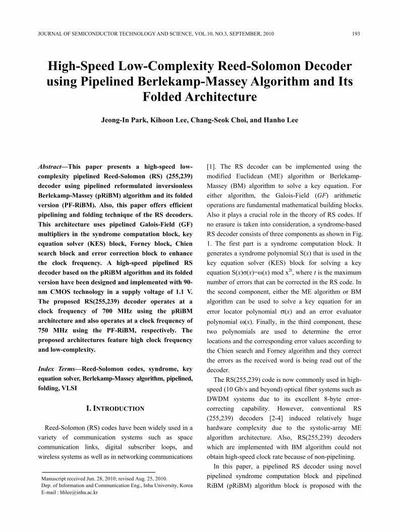
[1]. The RS decoder can be implemented using the modified Euclidean (ME) algorithm or Berlekamp-Massey (BM) algorithm to sοlve a key equation. For either algorithm, the Galois-Field (GF) arithmetic operations are fundamental mathematical building blocks. Also it plays a crucial role in the theory of RS codes. If no erasure is taken into consideration, a syndrome-based RS decoder consists of three components as shown in Fig. 1. The first part is a syndrome computation block. It generates a syndrome polynomial S(x) that is used in the key equation solver (KES) block for solving a key equation S(x)σ(x)=ω(x) mod x2t, where t is the maximum number of errors that can be corrected in the RS code. In the second component, either the ME algorithm or BM algorithm can be used to solve a key equation for an error locator polynomial σ(x) and an error evaluator polynomial ω(x). Finally, in the third component, these two polynomials are used to determine the error locations and the corresponding error values according to the Chien search and Forney algorithm and they correct the errors as the received word is being read out of the decoder.
The RS(255,239) code is now commonly used in high-speed (10 Gb/s and beyond) optical fiber systems such as DWDM systems due to its excellent 8-byte error-correcting capability. However, conventional RS (255,239) decoders [2-4] induced relatively huge hardware complexity due to the systolic-array ME algorithm architecture. Also, RS(255,239) decoders which are implemented with BM algorithm could not obtain high-speed clock rate because of non-pipelining.
In this paper, a pipelined RS decoder using novel pipelined syndrome computation block and pipelined RiBM (pRiBM) algorithm block is proposed with the
194 JEONG-IN PARK et al : HIGH-SPEED LOW-COMPLEXITY REED-SOLOMON DECODER USING PIPELINED…
aim of reducing the hardware complexity and improving the clock frequency for the RS(255,239) decoders. In addition, this paper presents its folded KES architecture. This design uses the pipelined GF multiplier in the syndrome computation block, KES block, Forney block and Chien search block to enhance the clock frequency and provides low hardware complexity as compared to the conventional KES architectures.
This paper is organized as follows. Section II shows the prοposed architecture for the high-speed RS decoder using the pRiBM and PF-RiBM algorithm and illustrates the decoding process. Also, this paper proposes pipelining method for each sub-block such as syndrome computation block, Chien search block and Forney block. In Section III, we present implementation results and performance comparisons. Finally, we provide conclusions in Section IV.
II. PROPOSED RS(255,239) DECODER
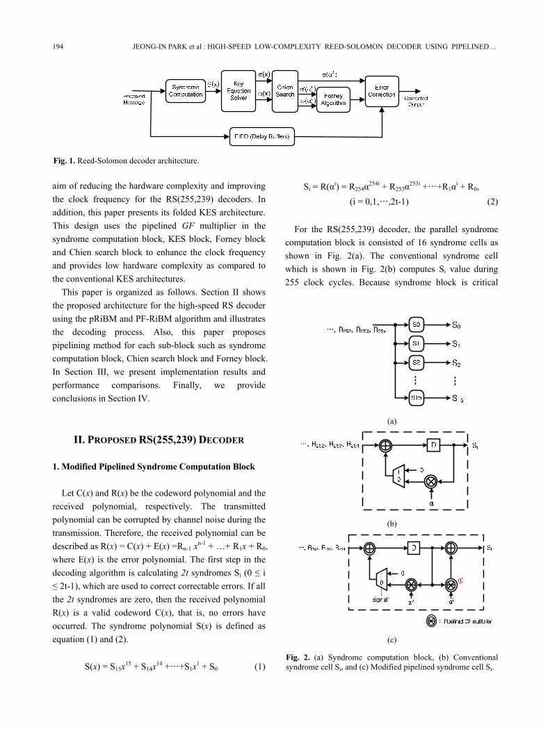
1. Modified Pipelined Syndrome Computation Block Let C(x) and R(x) be the codeword polynomial and the
received polynomial, respectively. The transmitted polynomial can be corrupted by channel noise during the transmission. Therefore, the received polynomial can be described as R(x) = C(x) + E(x) =Rn-1 xn-1 + …+ R1x + R0, where E(x) is the error polynomial. The first step in the decoding algorithm is calculating 2t syndromes Si (0 ≤ i ≤ 2t-1), which are used to correct correctable errors. If all the 2t syndromes are zero, then the received polynomial R(x) is a valid codeword C(x), that is, no errors have occurred. The syndrome polynomial S(x) is defined as equation (1) and (2).
S(x) = S15x15 + S14x14 +…+S1x1 + S0 (1)
Si = R(αi) = R254α254i + R253α253i +…+R1αi + R0, (i = 0,1,…,2t-1) (2)
For the RS(255,239) decoder, the parallel syndrome
computation block is consisted of 16 syndrome cells as shown in Fig. 2(a). The conventional syndrome cell which is shown in Fig. 2(b) computes Si value during 255 clock cycles. Because syndrome block is critical
Fig. 1. Reed-Solomon decoder architecture.
(a)
(b)
(c)
Fig. 2. (a) Syndrome computation block, (b) Conventional syndrome cell Si, and (c) Modified pipelined syndrome cell Si.
JOURNAL OF SEMICONDUCTOR TECHNOLOGY AND SCIENCE, VOL.10, NO.3, SEPTEMBER, 2010 195
path in the RS decoder if the KES block is pipelined, it is crucial that the conventional syndrome block is pipelined to enhance the clock frequency. But due to its feedback loop, applying pipelining technique to the syndrome block will make its latency double. To resolve this problem, equation (2) is reformulated by separating even term and odd term as follows:
Si(αi) = Reven(αi) + Rodd(αi)
= (R254α254i + R252α252i +…+R2α2i + R0) + (R253α253i + R251α251i +…+R1αi)
= (R254α2i*127 + R252α2i*126 +…+ R2α2i + R0) + (R253α2i*126 + R251α2i*125 +…+ R1) αi (3)
Fig. 2(c) shows the modified pipelined syndrome cell.
The input of constant GF multiplier should be changed from αi to α2i. At the 255th clock, even terms of S(x) is stored in the D-FF and the value of odd terms is stored in the output of constant GF multiplier ① in order to fulfill the equation (3). The odd terms are needed to be multiplied by αi at the 255th clock cycle according to equation (3). Single MUX and a GF adder were added to the conventional syndrome cell. By implementing the syndrome computation block in this manner, the critical path delay of the modified syndrome computation block is reduced to 3Txor+Tmux+Tff without increasing the latency.
2. Pipelined Galois-Field Multiplier
Let A and B be the multiplier and multiplicand over
GF (2m), respectively. A and B can be described as equation (4).
∑−
=
−− =+++=
1
0
1110
m
i
ii
mm aaaaA ααα L
∑−
=
−− =+++=
1
0
1110
m
i
ii
mm bbbbB ααα L (4)
Then, their product Z can be described as equation (5).
∑∑−
=
−
=
=⋅=⋅=1
0
1
0)(
m
i
ii
m
i
ii AbbABAZ αα (5)
Equation (5) is described by matrix form as equation (6).
⎥⎥⎥⎥⎥⎥
⎦
⎤
⎢⎢⎢⎢⎢⎢
⎣
⎡
=
−
−−
1
2110110 )()(
m
mm
A
AA
A
bbbzzz
α
αα
M
LL (6)
In the RS(255,239) code, equation (6) can be
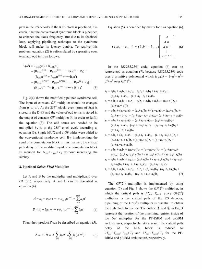
represented as equation (7), because RS(255,239) code uses a primitive polynomial which is p(x) = 1+α2+ α3+ α4+ α8 over GF(28).
z0 = a0b0 + a7b1 + a6b2 + a5b3 + a4b4 + (a3+a7)b5 +
(a2+a6+a7)b6 + (a1+ a5+ a6+ a7)b7 z1 = a1b0 + a0b1 + a7b2 + a6b3 + a5b4 + a4b5 + (a3+a7)b6 +
(a2+ a6+ a7)b7 z2 = a2b0 + (a1+a7)b1 + (a0+a6)b2 + (a5+a7)b3 + (a4+a6)b4 +
(a3+a5+ a7)b5 + (a2+ a4+ a6+ a7)b6 + (a1+ a3+ a5+ a6)b7 z3 = a3b0 + (a2+a7)b1 + (a1+a6+a7)b2 + (a0+a5+a3)b3 +
(a4+a5+a7)b4 +(a3+a4+a6+a7)b5 + (a2+a3+a5+a6)b6 + (a1+a2+ a4+ a5)b7
z4 = a4b0 + (a3+a7)b1 + (a2+a6+a7)b2 + (a1+a5+a6+a7)b3 + (a0+a4+a5+a6)b4 +(a3+a4+a5)b5 + (a2+a3+a4)b6 + (a1+a2+a3+ a7)b7
z5 = a5b0 + a4b1 + (a3+a7)b2 + (a2+a6+a7)b3 + (a1+a5+a6+ a7)b4 +(a0+a4+a5+a6)b5 + (a3+a4+a5)b6 + (a2+a3+ a4)b7
z6 = a6b0 + a5b1 + a4b2 + (a3+a7)b3 + (a2+a6+a7)b4 + (a1+a5+ a6+a7)b5 + (a0+a4+a5+a6)b6 + (a3+a4+ a5)b7
z7 = a7b0 + a6b1 + a5b2 + a4b3 + (a3+a7)b4 +(a2+a6+a7)b5 + (a1+a5+a6+a7)b6 + (a0+a4+ a5+ a6)b7 (7)
The GF(28) multiplier is implemented by using
equation (7) and Fig. 3 shows the GF(28) multiplier, in which the critical path is 5Txor+Tnand. Since GF(28) multiplier is the critical path of the RS decoder, pipelining of the GF(28) multiplier is essential to obtain the high clock frequency. The cutline ① and ② in Fig. 3 represent the location of the pipelining register inside of the GF multiplier for the PF-RiBM and pRiBM architectures, respectively. As a result, the critical path delay of the KES block is reduced to 2Txor+Tnand+Tmux+Tff and 3Txor+Tnand+Tff for the PF-RiBM and pRiBM architecture, respectively.
196 JEONG-IN PARK et al : HIGH-SPEED LOW-COMPLEXITY REED-SOLOMON DECODER USING PIPELINED…
3. Pipelined RiBM Architecture Many of conventional high-speed RS decoders have
used ME algorithm to solve the KES block because ME algorithm can easily adapt a fully pipelined systolic architecture. On the other hand, the hardware complexity of the ME architectures are higher than the Reformulated inverseless BM (RiBM) algorithm architecture introduced in [5]. Before we proceed, we provide a brief overview of the RiBM algorithm.
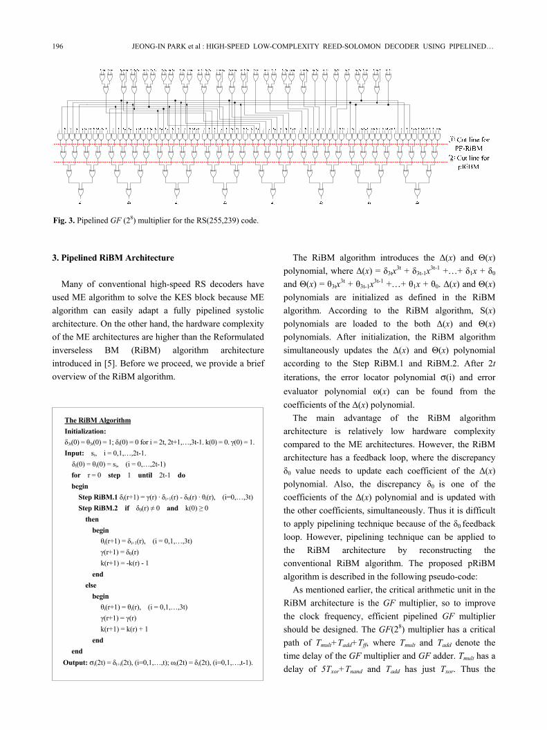
The RiBM algorithm introduces the Δ(x) and Θ(x) polynomial, where Δ(x) = δ3tx3t + δ3t-1x3t-1 +…+ δ1x + δ0 and Θ(x) = θ3tx3t + θ3t-1x3t-1 +…+ θ1x + θ0. Δ(x) and Θ(x) polynomials are initialized as defined in the RiBM algorithm. According to the RiBM algorithm, S(x) polynomials are loaded to the both Δ(x) and Θ(x) polynomials. After initialization, the RiBM algorithm simultaneously updates the Δ(x) and Θ(x) polynomial according to the Step RiBM.1 and RiBM.2. After 2t iterations, the error locator polynomial σ(i) and error evaluator polynomial ω(x) can be found from the coefficients of the Δ(x) polynomial.
The main advantage of the RiBM algorithm architecture is relatively low hardware complexity compared to the ME architectures. However, the RiBM architecture has a feedback loop, where the discrepancy δ0 value needs to update each coefficient of the Δ(x) polynomial. Also, the discrepancy δ0 is one of the coefficients of the Δ(x) polynomial and is updated with the other coefficients, simultaneously. Thus it is difficult to apply pipelining technique because of the δ0 feedback loop. However, pipelining technique can be applied to the RiBM architecture by reconstructing the conventional RiBM algorithm. The proposed pRiBM algorithm is described in the following pseudo-code:
As mentioned earlier, the critical arithmetic unit in the RiBM architecture is the GF multiplier, so to improve the clock frequency, efficient pipelined GF multiplier should be designed. The GF(28) multiplier has a critical path of Tmult+Tadd+Tff, where Tmult and Tadd denote the time delay of the GF multiplier and GF adder. Tmult has a delay of 5Txor+Tnand and Tadd has just Txor. Thus the
Fig. 3. Pipelined GF (28) multiplier for the RS(255,239) code.
The RiBM Algorithm Initialization: δ3t(0) = θ3t(0) = 1; δi(0) = 0 for i = 2t, 2t+1,…,3t-1. k(0) = 0. γ(0) = 1. Input: si, i = 0,1,…,2t-1. δi(0) = θi(0) = si, (i = 0,…,2t-1) for r = 0 step 1 until 2t-1 do begin
Step RiBM.1 δi(r+1) = γ(r) · δi+1(r) - δ0(r) · θi(r), (i=0,…,3t) Step RiBM.2 if δ0(r) ≠ 0 and k(0) ≥ 0
then begin
θi(r+1) = δi+1(r), (i = 0,1,…,3t) γ(r+1) = δ0(r) k(r+1) = -k(r) - 1
end else
begin θi(r+1) = θi(r), (i = 0,1,…,3t) γ(r+1) = γ(r) k(r+1) = k(r) + 1
end end
Output: σi(2t) = δt+i(2t), (i=0,1,…,t); ωi(2t) = δi(2t), (i=0,1,…,t-1).
JOURNAL OF SEMICONDUCTOR TECHNOLOGY AND SCIENCE, VOL.10, NO.3, SEPTEMBER, 2010 197
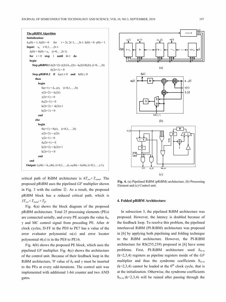
critical path of RiBM architecture is 6Txor+Tnand. The proposed pRiBM uses the pipelined GF multiplier shown in Fig. 3 with the cutline ②. As a result, the proposed pRiBM block has a reduced critical path, which is 3Txor+Tnand +Tff.
Fig. 4(a) shows the block diagram of the proposed pRiBM architecture. Total 25 processing elements (PEs) are connected serially, and every PE accepts the value δ0, γ and MC control signal from preceding PE. After 4t clock cycles, D-FF in the PE0 to PE7 has a value of the error evaluator polynomial ω(x) and error locator polynomial σ(x) is in the PE8 to PE16.
Fig. 4(b) shows the proposed PE block, which uses the pipelined GF multiplier. Fig. 4(c) shows the architecture of the control unit. Because of their feedback loop in the RiBM architecture, '0' value of δ0 and γ must be inserted to the PEs at every odd-iterations. The control unit was implemented with additional 1-bit counter and two AND gates.
4. Folded pRiBM Architecture
In subsection 3, the pipelined RiBM architecture was
proposed. However, the latency is doubled because of the feedback loop. To resolve this problem, the pipelined interleaved RiBM (PI-RiBM) architecture was proposed in [6] by applying both pipelining and folding technique to the RiBM architecture. However, the PI-RiBM architecture for RS(255,239) proposed in [6] have some problems. First, PI-RiBM architecture used δ5i+k
(k=2,3,4) registers as pipeline registers inside of the GF multiplier and thus the syndrome coefficients S5i+k
(k=2,3,4) cannot be loaded at the 0th clock cycle, that is at the initialization. Otherwise, the syndrome coefficients S5i+k (k=2,3,4) will be ruined after passing through the
The pRiBM Algorithm Initialization: δ3t(0) = 1; δi(0) = 0 for i = 2t, 2t+1,…,3t-1. k(0) = 0. γ(0) = 1. Input: si, i=0,1,…,2t-1. δi(0) = θi(0) = si, (i=0,…,2t-1) for r = 0 step 1 until 4t-1 do begin
Step pRiBM.1 δi(2r+2)=γ(2r)·δi+1(2r) - δ0(2r)·θi(2r), (i=0,…,3t) δi(2r+1) = 0
Step pRiBM.2 if δ0(r) ≠ 0 and k(0) ≥ 0 then
begin θi(r+1) = δi+1(r), (i=0,1,…,3t) γ(2r+2) = δ0(2r) γ(2r+1) = 0 δ0(2r+1) = 0 k(2r+2) = -k(2r)-1 k(2r+1) = 0
end else
begin θi(r+1) = θi(r), (i=0,1,…,3t) γ(2r+2) = γ(2r) γ(2r+1) = 0 δ0(2r+1) = 0 k(2r+2) = k(2r)+1 k(2r+1) = 0
end end
Output: λi(4t) = δt+i(4t), (i=0,1,…,t); ωi(4t) = δi(4t), (i=0,1,…,t-1).
γ(r)
(a)
γ(r)
(b)
γ(r) (c)
Fig. 4. (a) Pipelined RiBM (pRiBM) architecture, (b) Processing Element and (c) Control unit.
198 JEONG-IN PARK et al : HIGH-SPEED LOW-COMPLEXITY REED-SOLOMON DECODER USING PIPELINED…
GF multiplier. As a result, the PI-RiBM architecture needs additional initialization logic. Second, the PI-RiBM architecture has a middle register in the PEs, which is timing register. Since the number of the middle register increases according to the folding factors, it has a little advantage in the hardware complexity when the folding factor is high.
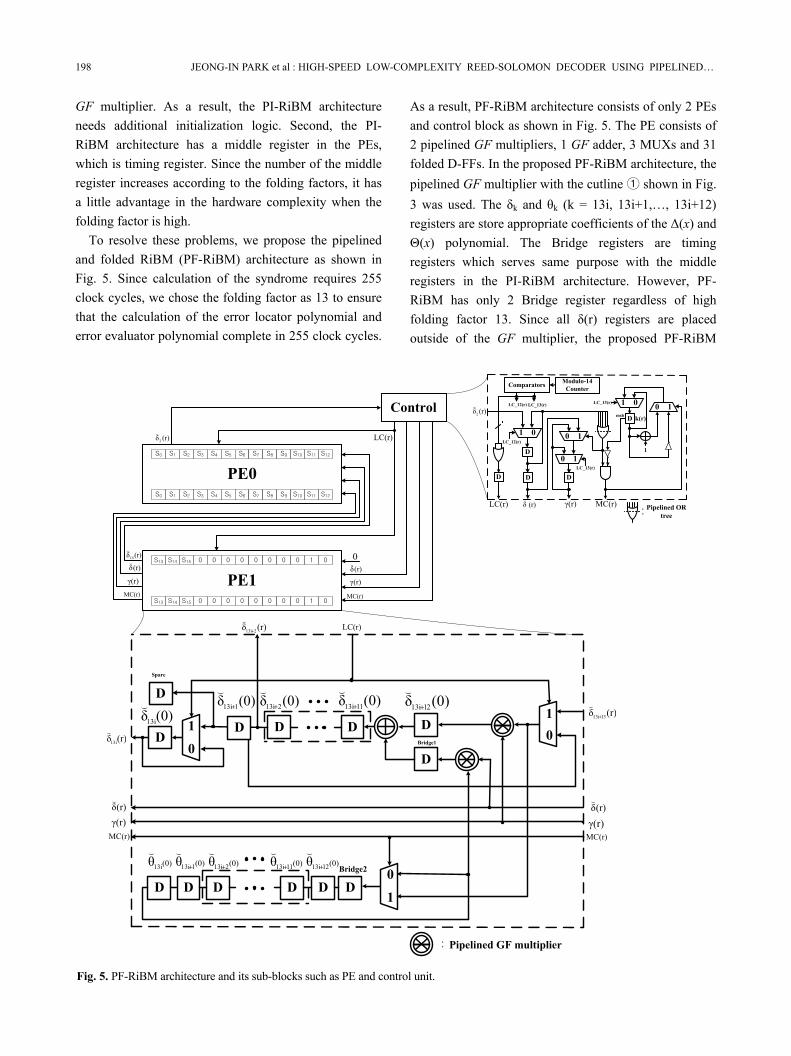
To resolve these problems, we propose the pipelined and folded RiBM (PF-RiBM) architecture as shown in Fig. 5. Since calculation of the syndrome requires 255 clock cycles, we chose the folding factor as 13 to ensure that the calculation of the error locator polynomial and error evaluator polynomial complete in 255 clock cycles.
As a result, PF-RiBM architecture consists of only 2 PEs and control block as shown in Fig. 5. The PE consists of 2 pipelined GF multipliers, 1 GF adder, 3 MUXs and 31 folded D-FFs. In the proposed PF-RiBM architecture, the pipelined GF multiplier with the cutline ① shown in Fig. 3 was used. The δk and θk (k = 13i, 13i+1,…, 13i+12) registers are store appropriate coefficients of the Δ(x) and Θ(x) polynomial. The Bridge registers are timing registers which serves same purpose with the middle registers in the PI-RiBM architecture. However, PF-RiBM has only 2 Bridge register regardless of high folding factor 13. Since all δ(r) registers are placed outside of the GF multiplier, the proposed PF-RiBM
PE0
D1
0D D D
D
D D D D D D0
1
LC(r)
10
Pipelined GF multiplier:
Bridge1
Bridge2
(r)δ 213i+
(
(r)δ13i
(
(r)δ 3113i+
( (0)δ13i
( (0)δ 113i+
( (0)δ 213i+
( (0)δ 1113i+
( (0)δ 2113i+
(
MC(r)γ(r)
(r)δ(
(0) (0) (0) (0) (0) 2113i1113i213i113i13i θθθθθ ++++
(((((MC(r)γ(r)
(r)δ(
D
1 0 0 1
0 1
Modulo-14CounterComparators
LC(r) MC(r)
LC_12(r) LC_13(r)
LC_13(r)
LC_12(r)
(r)δ2
(
(r)δ( γ(r)
D D
D
D
1 0 0 1D
LC_13(r)
1
k(r)msb
Pipelined OR tree:
DSpare
Control
0
(r)δ2
(LC(r)
(r)δ13i
(
MC(r)
γ(r)
(r)δ(
MC(r)
γ(r)
(r)δ(
PE1
S0 S1 S2 S3 S4 S5 S6 S7 S8 S9 S10 S11 S12
S0 S1 S2 S3 S4 S5 S6 S7 S8 S9 S10 S11 S12
S13 S14 S15 0 0 0 0 0 0 0 0 1 0
S13 S14 S15 0 0 0 0 0 0 0 0 1 0
Fig. 5. PF-RiBM architecture and its sub-blocks such as PE and control unit.
JOURNAL OF SEMICONDUCTOR TECHNOLOGY AND SCIENCE, VOL.10, NO.3, SEPTEMBER, 2010 199
architecture can initialize the whole syndrome polynomial at the 0th clock cycle as the RiBM architecture. However, to do that, the registers in the GF multiplier contains redundant data. But it offers less hardware complexity than additional initialization logic, which needed in the PI-RiBM architecture.
To execute the 1 iteration of the RiBM algorithm, the PF-RiBM architecture requires 14 clock cycles due to 13 folding factor plus 1 pipeline stage in the GF multiplier. Therefore the RiBM algorithm is completed after 224 clock cycles. However at the 224 clock cycle, δ13i+12 and Bridge1 register stores γ(r) · δ13i+13(r) and δ0(r) · θi(r) value respectively and calculation of the coefficient δ13i+12(r) is completed after processed by the GF adder. Thus after 1 clock cycle, the coefficient δ13i(r) is stored in the δ13i(r) resiger, δ13i+1(r) is in the Spare register, and δk(r) (k=13i+2, 13i+3, …, 13i+12) are in the δk-1(r) registers. As a result, the proposed PF-RiBM architecture requires 225 clock cycles to complete the RiBM algorithm.
The architecture of the control block is shown in Fig. 5. To control the 1 iteration of the RiBM algorithm, the control block is retimed by adding the modulo-14 counter, comparator and several MUXs to the control block. And the outputs of the control block are pipelined to ensure the critical path delay does not occur in the control block. In short, the proposed PF-RiBM architecture offers very low hardware complexity by using only 2 PEs and calculates the error locator polynomial and error evaluator polynomial during 225 clock cycles with the critical path delay of 2Txor+Tmux
+Tnand+Tff for the RS(255,239) decoders.
5. Pipelined Chien Search Block, Forney Block and Error Correction Block
After the KES block, the error locator polynomial σ(x)
and the error value polynomial ω(x) are fed into the Chien search block and Forney block, respectively. Chien search block calculates the roots of the error locator polynomial. The Forney block works in parallel with the Chien search block to calculate the magnitude of the error symbol at each error location. Let the error locator polynomial of degree n over GF(2m) be defined by, σ(x) = xt + σt-1xt-1 +…+ σ0, where the coefficients σi ∈ GF(2m) for 0 ≤ i ≤ t-1. Then, finding the roots of such
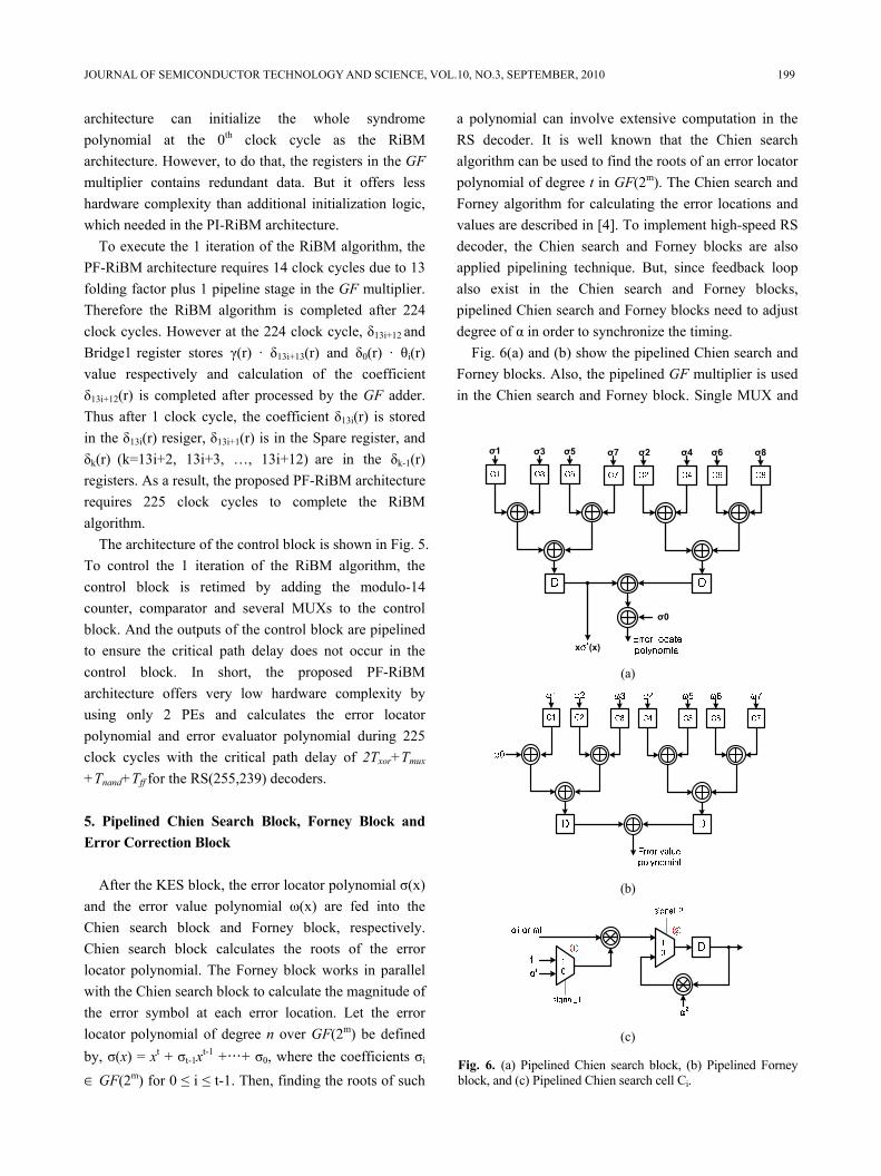
a polynomial can involve extensive computation in the RS decoder. It is well known that the Chien search algorithm can be used to find the roots of an error locator polynomial of degree t in GF(2m). The Chien search and Forney algorithm for calculating the error locations and values are described in [4]. To implement high-speed RS decoder, the Chien search and Forney blocks are also applied pipelining technique. But, since feedback loop also exist in the Chien search and Forney blocks, pipelined Chien search and Forney blocks need to adjust degree of α in order to synchronize the timing.
Fig. 6(a) and (b) show the pipelined Chien search and Forney blocks. Also, the pipelined GF multiplier is used in the Chien search and Forney block. Single MUX and
σ1
σ0
σ3 σ5 σ7 σ2 σ4 σ6 σ8
x (x) (a)
(b)
(c)
Fig. 6. (a) Pipelined Chien search block, (b) Pipelined Forneyblock, and (c) Pipelined Chien search cell Ci.
200 JEONG-IN PARK et al : HIGH-SPEED LOW-COMPLEXITY REED-SOLOMON DECODER USING PIPELINED…
the pipelined GF multiplier are added to the conventional Chien search cell. Fig. 6(c) shows pipelined Chien search cell. Two initial value [1, αi] are used for pipelined Chien search cell. At the first clock, MUX ① selects ‘1’, and at the second clock, MUX ① toggled. After 3 clock cycles, MUX ② toggled to the ‘0’. Then proposed Chien search cell can be processed iteratively. As a result, the critical path of the proposed Chien search and Forney block became 3Txor+Tmux+Tff in expense of only a modest increase in hardware complexity and single clock latency.
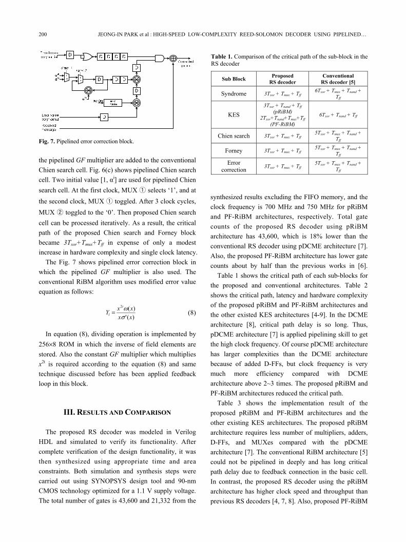
The Fig. 7 shows pipelined error correction block in which the pipelined GF multiplier is also used. The conventional RiBM algorithm uses modified error value equation as follows:
)(')(2
xxxxY
t
l σω= (8)
In equation (8), dividing operation is implemented by
256×8 ROM in which the inverse of field elements are stored. Also the constant GF multiplier which multiplies x2t is required according to the equation (8) and same technique discussed before has been applied feedback loop in this block.
III. RESULTS AND COMPARISON
The proposed RS decoder was modeled in Verilog HDL and simulated to verify its functionality. After complete verification of the design functionality, it was then synthesized using appropriate time and area constraints. Both simulation and synthesis steps were carried out using SYNOPSYS design tool and 90-nm CMOS technology optimized for a 1.1 V supply voltage. The total number of gates is 43,600 and 21,332 from the
synthesized results excluding the FIFO memory, and the clock frequency is 700 MHz and 750 MHz for pRiBM and PF-RiBM architectures, respectively. Total gate counts of the proposed RS decoder using pRiBM architecture has 43,600, which is 18% lower than the conventional RS decoder using pDCME architecture [7]. Also, the proposed PF-RiBM architecture has lower gate counts about by half than the previous works in [6].
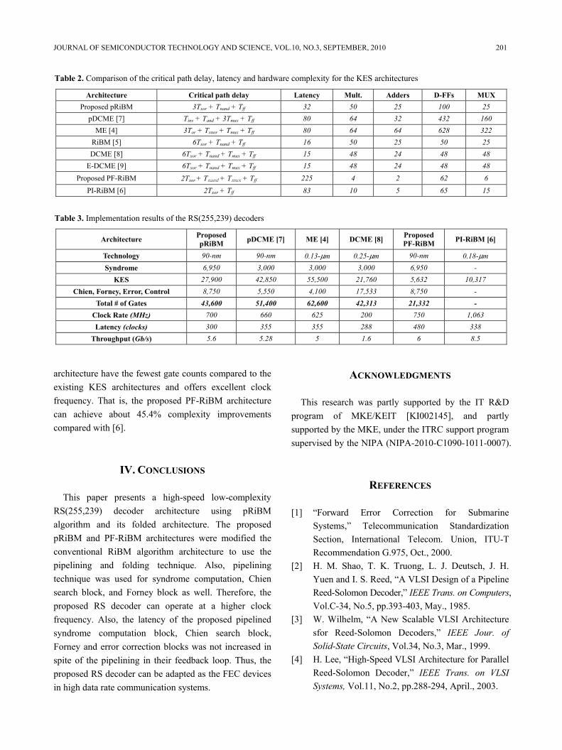
Table 1 shows the critical path of each sub-blocks for the proposed and conventional architectures. Table 2 shows the critical path, latency and hardware complexity of the proposed pRiBM and PF-RiBM architectures and the other existed KES architectures [4-9]. In the DCME architecture [8], critical path delay is so long. Thus, pDCME architecture [7] is applied pipelining skill to get the high clock frequency. Of course pDCME architecture has larger complexities than the DCME architecture because of added D-FFs, but clock frequency is very much more efficiency compared with DCME architecture above 2~3 times. The proposed pRiBM and PF-RiBM architectures reduced the critical path.
Table 3 shows the implementation result of the proposed pRiBM and PF-RiBM architectures and the other existing KES architectures. The proposed pRiBM architecture requires less number of multipliers, adders, D-FFs, and MUXes compared with the pDCME architecture [7]. The conventional RiBM architecture [5] could not be pipelined in deeply and has long critical path delay due to feedback connection in the basic cell. In contrast, the proposed RS decoder using the pRiBM architecture has higher clock speed and throughput than previous RS decoders [4, 7, 8]. Also, proposed PF-RiBM
Fig. 7. Pipelined error correction block.
Table 1. Comparison of the critical path of the sub-block in the RS decoder
Sub Block Proposed RS decoder
Conventional RS decoder [5]
Syndrome 3Txor + Tmux + Tff 6Txor + Tmux + Tnand +
Tff
KES 3Txor + Tnand + Tff
(pRiBM) 2Txor+Tnand+Tmux+Tff
(PF-RiBM)
6Txor + Tnand + Tff
Chien search 3Txor + Tmux + Tff 5Txor + Tmux + Tnand +
Tff
Forney 3Txor + Tmux + Tff 5Txor + Tmux + Tnand +
Tff
Error correction 3Txor + Tmux + Tff
5Txor + Tmux + Tnand + Tff
JOURNAL OF SEMICONDUCTOR TECHNOLOGY AND SCIENCE, VOL.10, NO.3, SEPTEMBER, 2010 201
architecture have the fewest gate counts compared to the existing KES architectures and offers excellent clock frequency. That is, the proposed PF-RiBM architecture can achieve about 45.4% complexity improvements compared with [6].
IV. CONCLUSIONS
This paper presents a high-speed low-complexity RS(255,239) decoder architecture using pRiBM algorithm and its folded architecture. The proposed pRiBM and PF-RiBM architectures were modified the conventional RiBM algorithm architecture to use the pipelining and folding technique. Also, pipelining technique was used for syndrome computation, Chien search block, and Forney block as well. Therefore, the proposed RS decoder can operate at a higher clock frequency. Also, the latency of the proposed pipelined syndrome computation block, Chien search block, Forney and error correction blocks was not increased in spite of the pipelining in their feedback loop. Thus, the proposed RS decoder can be adapted as the FEC devices in high data rate communication systems.
ACKNOWLEDGMENTS
This research was partly supported by the IT R&D program of MKE/KEIT [KI002145], and partly supported by the MKE, under the ITRC support program supervised by the NIPA (NIPA-2010-C1090-1011-0007).
REFERENCES
[1] “Forward Error Correction for Submarine Systems,” Telecommunication Standardization Section, International Telecom. Union, ITU-T Recommendation G.975, Oct., 2000.
[2] H. M. Shao, T. K. Truong, L. J. Deutsch, J. H. Yuen and I. S. Reed, “A VLSI Design of a Pipeline Reed-Solomon Decoder,” IEEE Trans. on Computers, Vol.C-34, No.5, pp.393-403, May., 1985.
[3] W. Wilhelm, “A New Scalable VLSI Architecture sfor Reed-Solomon Decoders,” IEEE Jour. of Solid-State Circuits, Vol.34, No.3, Mar., 1999.
[4] H. Lee, “High-Speed VLSI Architecture for Parallel Reed-Solomon Decoder,” IEEE Trans. on VLSI Systems, Vol.11, No.2, pp.288-294, April., 2003.
Table 2. Comparison of the critical path delay, latency and hardware complexity for the KES architectures
Architecture Critical path delay Latency Mult. Adders D-FFs MUX Proposed pRiBM 3Txor + Tnand + Tff 32 50 25 100 25
pDCME [7] Tinv + Tand + 3Tmux + Tff 80 64 32 432 160 ME [4] 3Tor + Txnor + Tmux + Tff 80 64 64 628 322
RiBM [5] 6Txor + Tnand + Tff 16 50 25 50 25 DCME [8] 6Txor + Tnand + Tmux + Tff 15 48 24 48 48
E-DCME [9] 6Txor + Tnand + Tmux + Tff 15 48 24 48 48 Proposed PF-RiBM 2Txor + Tnand + Tmux + Tff 225 4 2 62 6
PI-RiBM [6] 2Txor + Tff 83 10 5 65 15
Table 3. Implementation results of the RS(255,239) decoders
Architecture Proposed pRiBM pDCME [7] ME [4] DCME [8] Proposed
PF-RiBM PI-RiBM [6]
Technology 90-nm 90-nm 0.13-μm 0.25-μm 90-nm 0.18-μm Syndrome 6,950 3,000 3,000 3,000 6,950 -
KES 27,900 42,850 55,500 21,760 5,632 10,317 Chien, Forney, Error, Control 8,750 5,550 4,100 17,533 8,750 -
Total # of Gates 43,600 51,400 62,600 42,313 21,332 - Clock Rate (MHz) 700 660 625 200 750 1,063 Latency (clocks) 300 355 355 288 480 338
Throughput (Gb/s) 5.6 5.28 5 1.6 6 8.5
202 JEONG-IN PARK et al : HIGH-SPEED LOW-COMPLEXITY REED-SOLOMON DECODER USING PIPELINED…
[5] D. V. Sarwate and N. R. Shanbhag, “High-Speed Architecture for Reed-Solomon Decoders,” IEEE Trans. on VLSI Systems, Vol.9, No.5, pp.641-655, Oct., 2001.
[6] B. Yuan, L. Li and Z. Wang, “Area-Efficient Reed-Solomon Decoder Design for 10-100Gb/s Applications,” in Proc. IEEE Int. Symp. Circ. and Syst. (ISCAS’2009), pp.2681-2684, May, 2009.
[7] S. Lee and H. Lee, “A High-Speed Pipelined Degree-Computationless Modified Euclidean Algorithm Architecture for Reed-Solomon Decoders,” IEICE Trans. on Fund. of Electronics, Communications, and Computer Sciences, Vol.E91-A, No.3, pp.830-835, March, 2008.
[8] J. H. Baek and M. H. Sunwoo, “New Degree Computationless Modified Euclidean Algorithm and Architecture for Reed-Solomon Decoder,” IEEE Trans. on VLSI Systems, Vol.14, No.8, pp.915-920, Aug., 2006.
[9] J. H. Baek and M. H. Sunwoo, “Enhanced degree computationless modified Euclid’s algorithm for Reed-Solomon decoders,” Electronics Letters-IEE, Vol.43, No.3, pp.175-176, Feb., 2007.
Jeong-In Park received the B.S. degree in the Information and Communication Engineering in 2009, from Inha University, Korea, where he is currently working toward the M.S degree. His interests include not only digital VLSI circuits and
systems design for communications such as forward error correction codes but also their efficient hardware implementation.
Kihoon Lee received the B.S. degree in the Information & Communication Engineering in 2009, from Inha University, Incheon, Korea, where he is currently working toward the M.S degree. His research interests are digital VLSI circuits and systems
design for communications, with emphasis on designing encoding and decoding algorithms for forward error correction codes and their efficient hardware implementation.
Chang-Seok Choi received B.S degree in information and communi-cation engineering from Hanshin University in 2005 and M.S. degree in information and communication engineering from Inha University, Incheon, Korea, in 2007, respectively.
He is currently working toward the Ph.D degree in Inha University. His research interests are design and implementation of VLSI, especially reconfigurable hardware systems.
Hanho Lee received the Ph.D. and M.S. degrees, both in Electrical & Computer Engineering, from the University of Minnesota, Minneapolis, in 2000 and 1996 respectively, and the B.S. degree in Electronics Engineering from Chungbuk National
University, S. Korea, in 1993. In 1999, he was a Member of Technical-Staff-1 at Lucent Technologies, Bell Labs, Holmdel, NJ. From April 2000 to August 2002, he was a Member of Technical Staff at the Lucent Technologies (Bell Labs Innovation), Allentown, where he was responsible for the development of VLSI architectures and implementation of high-performance DSP multiprocessor SoC for wireless infrastructure systems. From August 2002 to August 2004, he was an assistant professor at the Department of Electrical & Computer Engineering, University of Connecticut. Since August 2004, he has been with the School of Information and Communication Engineering, Inha University, where he is presently an Associate Professor. His research interests include design of VLSI circuits and systems for communications, System-on-a-Chip (SoC) design, reconfigurable architecture, and forward error correction coding.