high-side intelligent power switches for industrial and...
TRANSCRIPT

External Use
TM
Béatrice Bernoux | Technical Marketer
High-Side Intelligent Power
Switches for Industrial and
Automotive Applications
FTF-AUT-F0179
A P R . 2 0 1 4

TM
External Use 1
Agenda
• Introduction and Agenda Review
• Market Environment
• Technology Review
• Product Review and Impact on Solutions
• Ecosystem and Design Support
• Session Review and Wrap-up

TM
External Use 2
Session Introduction
• Freescale’s intelligent high side switches are designed to control a
wide variety of loads in automotive and industrial systems. This
presentation describes Freescale’s high side switch portfolio and
roadmap, device features, potential applications and available
design and support tools.
• By completing this 1h training, you will be able to:
− Describe the capabilities of the products that will help you meet your
design challenges, and how they can provide you a
competitive/differentiating advantage
− Determine which eXtreme Switch family fits your target
market/application

TM
External Use 3
Market Environment

TM
External Use 4
Market and Trends for Energy Distribution
Fuse Box (using MC33982 & 984)
Energy Distribution with SmartPower
• Today:
− Most applications use fuses / relays
• Trend:
− Regulation; CO2 emissions
− Reduce weight and size
− Warranty extension: Need very robust design
− More comfort: Silence/noise
− Euro6 constraints
− Fuse box not accessible

TM
External Use 5
SmartPower Benefits
SmartPower device is a Power IC with some digital content.
It interfaces between an MCU and a load.
“eXtreme Switch” is Freescale’s brand name for high-current “SmartPower”.
Why use SmartPower devices instead of relays?
Lighter weight, smaller systems
Integration
Self protection, diagnostic features
PWM capability EMC, di/dt and dv/dt control
Standby current few µA
No relay coil driver losses
Simple & Robust Design Switching Capability Power Dissipation

TM
External Use 6
Relay Replacement Evolution
Features Relay eXtreme
Switch
Load requiring <1A No Yes
PWM No Yes
Block reverse battery current Yes No
Diagnostics No Yes
Overcurrent management to protect wiring No Yes
H-bridge or ½ H-bridge topologies > 10A Yes No
TM
External Use 7
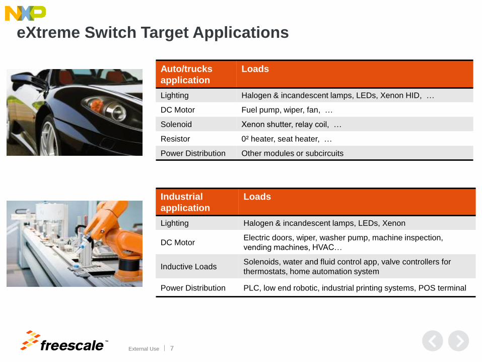
eXtreme Switch Target Applications
Auto/trucks
application
Loads
Lighting Halogen & incandescent lamps, LEDs, Xenon HID, …
DC Motor Fuel pump, wiper, fan, …
Solenoid Xenon shutter, relay coil, …
Resistor 0² heater, seat heater, …
Power Distribution Other modules or subcircuits
Industrial
application
Loads
Lighting Halogen & incandescent lamps, LEDs, Xenon
DC Motor Electric doors, wiper, washer pump, machine inspection,
vending machines, HVAC…
Inductive Loads Solenoids, water and fluid control app, valve controllers for
thermostats, home automation system
Power Distribution PLC, low end robotic, industrial printing systems, POS terminal

TM
External Use 8
Technology Review

TM
External Use 9
What is an eXtreme Switch?
High-side switch connected between supply and load
A dual-chip solution in a package: most optimized (cost) for given current (so far)
The eXtreme Switch limit of the load current is 1A-30A DC and 150A transient.
Loads are mostly bulbs, DC motors, solenoids or submodules
eXtreme Switch devices are available for:
− Automotive applications:
• 12V systems (45V technology): Lighting, “Main switch”, DC motor control
• 24V systems (65V technology): General purpose switch for trucks, buses and special engines
− Industrial applications
eXtreme Switch =
Power switch + Control logic + Protections + Diagnostic + Power package

TM
External Use 10
eXtreme Switch Composition
SMARTMOSTM
Protection and diagnostic • Over temperature (175°C)
• Over current shutdown
• Over/under voltage
• Short circuit
• Reverse battery
• Loss of ground/Vbat
• Energy discharge protection
SPI Interface • Easy connection to the uP
• Programmability
• Daisy chain using SPI
• Programmable over current trip level
• Watchdog
• Embedded PWM module
Vertical Power Stage
Best-in-class technology • Planar HD5 and TrenchFet LFET
• 45V & 65V BV
Protection in the power stage • Temperature sensor
• Current sensor
• Voltage sensor (Gen4)
Power Package
PQFN low cost power package • 0.5 mm thick lead frame
• Die soldered attached
• Rthj-c < 0.5°C/W
SOICeP32 and 54 • Designed for high power
• Large al wire capability
• Pb-free compliancy
TM
External Use 11
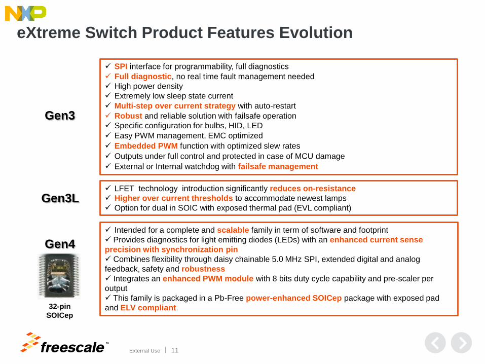
eXtreme Switch Product Features Evolution
SPI interface for programmability, full diagnostics
Full diagnostic, no real time fault management needed
High power density
Extremely low sleep state current
Multi-step over current strategy with auto-restart
Robust and reliable solution with failsafe operation
Specific configuration for bulbs, HID, LED
Easy PWM management, EMC optimized
Embedded PWM function with optimized slew rates
Outputs under full control and protected in case of MCU damage
External or Internal watchdog with failsafe management
LFET technology introduction significantly reduces on-resistance
Higher over current thresholds to accommodate newest lamps
Option for dual in SOIC with exposed thermal pad (EVL compliant)
Intended for a complete and scalable family in term of software and footprint
Provides diagnostics for light emitting diodes (LEDs) with an enhanced current sense
precision with synchronization pin
Combines flexibility through daisy chainable 5.0 MHz SPI, extended digital and analog
feedback, safety and robustness
Integrates an enhanced PWM module with 8 bits duty cycle capability and pre-scaler per
output
This family is packaged in a Pb-Free power-enhanced SOICep package with exposed pad
and ELV compliant.
Gen3
Gen3L
Gen4
32-pin
SOICep

TM
External Use 12
eXtreme Switch for 24V systems
• Operating profile for trucks might be 300,000 km/y
• Wire harness for 24V system is often much longer than in passenger vehicles
• Potentially up to 20 meters from module to load (up to 40 m with a trailer)
• Potentially up to 20 meters from battery to module (for a distributed architecture)
• Increases wiring inductance and the possibility of wiring harness faults
• 24V systems have more loads than 12V systems and more of those loads are motors and solenoids
• Motors are often PWMed @ ~1 kHz from 5% to 100% whereas lighting is PWMed at 100 to 200 Hz
• Vehicular transient specifications are more severe in 24V systems
Main Differences Between 12V and 24V Vehicular Systems

TM
External Use 13
eXtreme Switch Product Numbering
MC 22 XS 4 2 00 B EK / R2
QUALIFICATION STATUS
PC PRE-QUALIFICATION,
ENGINEERING SAMPLES
MC FULLY QUALIFIED
SC CUSTOM DEVICE
ON-RESISTANCE
22 = 22 mΩ
50 = 50 mΩ
TAPE AND REEL
R2 TAPE AND REEL
PACKAGE DESIGNATOR
EK Lead free SOIC
FK Lead free PQFN
FAMILY
XS = eXtreme SWITCH
GENERATION
3 = Gen 3
4 = 24V family
6 = Gen 4
NUMBER OF OUTPUTS
2 = 2 outputs
4 = 4 outputs
5 = 5 outputs
ON-RESISTANCE, SMALLEST OUTPUTS
00 = All output identical
Revision
__ = revision A
B = upgraded control die
BA = fastest device
Part Number
TM
External Use 14
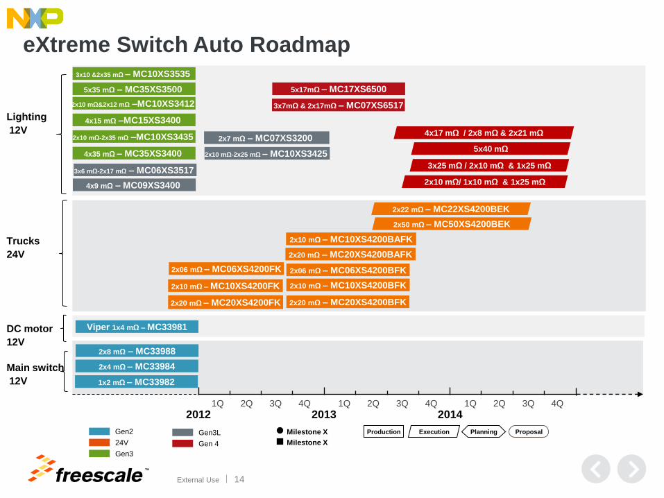
eXtreme Switch Auto Roadmap
Lighting
12V
Trucks
24V
DC motor
12V
Main switch
12V
Milestone X
Milestone X
Gen3L
Gen 4
Gen3
Gen2
24V
2012 2013 2014 2Q 3Q 4Q 1Q 2Q 3Q 4Q 1Q 2Q 3Q 4Q 1Q
Production Proposal Planning Execution
5x40 mΩ
4x17 mΩ / 2x8 mΩ & 2x21 mΩ
2x10 mΩ/ 1x10 mΩ & 1x25 mΩ
3x25 mΩ / 2x10 mΩ & 1x25 mΩ
2x06 mΩ – MC06XS4200FK
2x10 mΩ – MC10XS4200FK
2x20 mΩ – MC20XS4200FK
2x06 mΩ – MC06XS4200BFK
2x10 mΩ – MC10XS4200BFK
2x20 mΩ – MC20XS4200BFK
2x10 mΩ – MC10XS4200BAFK
2x20 mΩ – MC20XS4200BAFK
2x50 mΩ – MC50XS4200BEK
2x22 mΩ – MC22XS4200BEK
2x8 mΩ – MC33988
2x4 mΩ – MC33984
1x2 mΩ – MC33982
Viper 1x4 mΩ – MC33981
4x35 mΩ – MC35XS3400
2x10 mΩ-2x35 mΩ –MC10XS3435
4x15 mΩ –MC15XS3400
2x10 mΩ&2x12 mΩ –MC10XS3412
5x35 mΩ – MC35XS3500
3x10 &2x35 mΩ – MC10XS3535
3x6 mΩ-2x17 mΩ – MC06XS3517
4x9 mΩ – MC09XS3400
2x7 mΩ – MC07XS3200
2x10 mΩ-2x25 mΩ – MC10XS3425
5x17mΩ – MC17XS6500
3x7mΩ & 2x17mΩ – MC07XS6517

TM
External Use 15
eXtreme Switch IMM Roadmap
IMM
Max 20V
(extended range
28V)
IMM
Max 36V
(extended range
58V)
DC motor
Max 27V
Main switch
Max 32V
Milestone X
Milestone X
Gen3L
Gen 4
Gen3
Gen2
24V
2013 2014 4Q 3Q 2Q 1Q 4Q 3Q 2Q 1Q
Production Proposal Planning Execution
2x50 mΩ – MC50XSD200EK
2x22 mΩ – MC22XSD00EK
2x8 mΩ – MC34988
2x4 mΩ – MC34984
1x2 mΩ – MC34982
1x4 mΩ – MC34981
2x06 mΩ – MC06XSD200FK
2x10 mΩ – MC10XSD200FK
2x20 mΩ – MC20XSD200FK
5x17 mΩ – MC17XSF500
3x7 mΩ -2x17 mΩ – MC07XSF517 5x40 mΩ
4x17 mΩ / 2x8 mΩ – 2x21 mΩ
2x10 mΩ/ 1x10 mΩ – 1x25 mΩ
3x25 mΩ / 2x10 mΩ – 1x25 mΩ 2x7 mΩ – MC07XSC200
2x10 mΩ-2x25 mΩ – MC10XSC425

TM
External Use 16
Product Review and Impact on
Solutions
TM
External Use 17
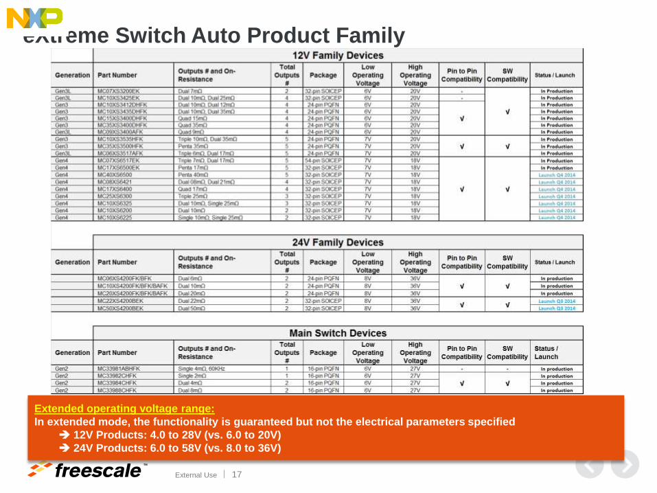
eXtreme Switch Auto Product Family
Extended operating voltage range:
In extended mode, the functionality is guaranteed but not the electrical parameters specified
12V Products: 4.0 to 28V (vs. 6.0 to 20V)
24V Products: 6.0 to 58V (vs. 8.0 to 36V)

TM
External Use 18
eXtreme Switch IMM Product Family

TM
External Use 19
22A / 14V Gen4 Penta eXtreme Switches MC07XS6517 / MC17XS6500
Differentiating Points:
• Robustness: Unique over-current latch-off protection, full
digital and accurate analog diagnostics, and protection
features with embedded failsafe mode
• Integration: Five configurable low Rdson channels with daisy-
chainable SPI
• Density: Thermally enhanced package for affordable high
switch count modules with up to 30% lower power, 30%
smaller PCB footprint and 50% fewer components
• Accuracy: Advanced current sensing over temperature and
supply voltage range allowing accurate current monitoring
from 27mA to 22A
• Scalability: Pin and SW driver compatible family
• Best thermal efficiency: Lowest Rdson in penta configuration
Typical Applications Transportation
o 12V lighting from high beam to LEDs
o Valves
Industrial
o High current / highly inductive loads
(solenoids)
o DC motor control
o Factory automation PLC
o Industrial lighting
Scalable family of 22A/14V programmable penta high-side switches with wide-range diagnostic
current sensing and lowest Rdson for up to 30% smaller PCB and 50% lower component count

TM
External Use 20
22A / 14V Gen4 Penta eXtreme Switches MC07XS6517 / MC17XS6500
Product features:
• Penta: 3x7 mΩ + 2x17 mΩ or Penta 5x17 mΩ
• Operating voltage range of 6.0 V to 18 V with sleep current
< 5.0 μA
• Flexibility Xenon / LED / Halogen (up to 11A, 22A )
• Lighting: from 25 Hz to 400 Hz
• Daisy chainable 16-bit 5 MHz SPI: control over-current
profiles, PWM duty-cycles, output-ON and -OFF open load
detections, thermal shut-down and fault reporting
• Individually programmable external PWM signal with 8-bit
duty cycle control.
• Channel round shaping for excellent EMC behavior
• Enhanced output current sense (down to 27.5 mA) with
programmable synchronization signal, ±5°C temperature
and ± 1% battery voltage feedback
• Watchdog and failsafe mode
• External smart power switch control
• Compatible PCB foot print and SPI software driver among
the family
• Current sense precision resistor can be shared among
many devices
SO
VBAT
GND
Selectable
Slope Control
CP
OUT1
Selectable Over-
current Protection
Temperature
Shut-down
Thermal
Prewarning
Selectable Open-
load Detection
Output Voltage
Monitoring
Selectable
Current Sensing
OUT1 Channel
SPI
PWM Module
Fault
Management
Logic
VCC
CS
SCLK
SI
RST
LIMP
IN1
IN2
IN3
IN4
CLK
CSNS
CSNS
SYNC\
OUT2
OUT3
OUT4
OUT5
Selectable
Analog
Feedback
Control die
Temperature
Monitoring
Battery
Voltage
Monitoring
OUT6
VCC
VBAT_PROTECTED
VBAT_PROTECTED
OUT2 Channel
OUT3 Channel
OUT4 Channel
OUT5 Channel
Wake OR RST
VCC
Reverse
Battery
Protection
OV
OTW1
OTW2
OTS1
OC1
OLON1
OLOFF1
OUT1
CL
KF
CPF
Charge
Pump
SPIF
VBAT_PROTECTEDPower
Supply
OUT4 Channel
Under-voltage
DetectionUVF
Clock Failure
Detection
Power-on
Reset
Vs
Selectable
Delay
Battery
Clamp
SP
I C
on
tro
lL
imp
Ho
me
Co
ntr
ol
Po
we
r c
ha
nn
els
Sm
art
Po
we
r
Sw
itc
h D
riv
e
VCC
A t
o D
Co
nv
ert
ion
VCC
VBAT100nF
5k
5k
Re
fere
nc
e
PW
M C
loc
k

TM
External Use 21
High Power Robustness Assessment: Gen4
Short-circuit case Battery voltage Supply Line Load Line Cycles w/o
failure
Comments
Turn-on into a short-
circuit condition
16V 5.0 µH / 10 mΩ 5.0 µH / 50 mΩ
1.0 µH / 20 mΩ
500k AECQ100-12
Short-circuit in on-state 14V 0.3 m / 2.5 mm²
5.0 m / 2.5 mm²
5.0 µH / 50 mΩ
1.0 µH / 20 mΩ
500k
On-state overload
95% OCHI1/2/3 levels
16V 0.3 m / 2.5 mm² 0.3 m / 1.0 mm² 500k
Test results AN
for AECQ100-12 stress
Tests performed at hot temp.

TM
External Use 22
24V eXtreme Switch Dual 6 mW – Dual 10 mW – Dual 20 mW – Dual 22 mW -Dual 50 mW
Differentiating Points:
• Robustness: Unique over-current latch-off protection,
full digital & analog diagnostic and protection features
with embedded failsafe mode
• Integration: Unique daisy-chainable SPI control for
dual low RDSon channels in a single package
• Accuracy: 5X better current sensing accuracy over
temperature & supply voltage range with unique
accurate temperature sensing capability
• Scalable: Compatible PCB foot print and SPI software
driver among the 36V product family
• Lowest Rdson in Dual Configuration: 20% smaller
PCB due to lower power dissipation when using
12A/channel or 24A/dual in a thermally enhanced
package
Typical Applications
Transportation 12 / 24V
o 24V lighting and capacitive loads
o Valves
o DC motors
Industrial
o High current / highly inductive loads
(solenoids)
o DC motor control
o Factory automation
Scalable, programmable family of 24V/36V SPI-driven, dual-channel, smart high-
side switches with lowest RDSon for up to a 30% board reduction

TM
External Use 23
24V eXtreme Switch Dual 6 mW – Dual 10 mW – Dual 20 mW – Dual 22 mW -Dual 50 mW
Few external components required
Product features:
• Dual 6,10,20,22,50 mΩ high side switches with possible
parallel output mode
• Operating voltage range: 8V to 36V. Extended range: 6V to
58V. Sleep mode current < 10 µA
• Flexibility for resistive/capacitive/inductive loads (up to 1 kHz)
• 3.3 V and 5.0 V compatible 16-bit daisy chainable SPI control
• Programmable over-current profiles, channel control including
PWM duty-cycles (8-bit), output-ON and -OFF open load
detections and fault reporting
• Individually programmable internal/external PWM clock
signals
• Temperature sensing (±5°C )& over temperature
shutdown for each channel
• Synchronous / asynchronous accurate current (±10%)
sensing
• External current sense precision resistor shared among
devices
• Watchdog and failsafe mode
• Hard or soft short-circuit + over temperature protection with
safe auto-retry
• Selectable slew rates to improve EMC performances

TM
External Use 24
eXtreme Switch Features and Benefits
Features Benefits
Lowest Rdson in thermally enhanced package Best thermal efficiency for 30% smaller footprint and best
module longevity with 30% lower power dissipation
Programmable dynamic threshold over-current and over-
temperature detection limits Optimized fault protection
Accurate temperature (±5 °C) and synchronous /
asynchronous current (±10%) sensing Advanced load diagnostics
Compatible devices and flexible load management from
high current (HID, 65W lamps) to low current LEDs
Hardware reuse across multiple applications and quick-turn
flexibility for tuning designs with ambiguous load requirement
Programmable fault auto-retry Auto recovery for transient faults
Watchdog and protected output in failsafe mode Ready for an SIL-B compliant module design
Selectable slew rate Optimize EMI vs. efficiency tradeoff
Individually programmable internal/external PWM signals Offloads MCU for software design simplicity & PPM reduction
16-bit daisy chainable SPI control BOM component & cost savings by eliminating series SPI
resistors between MCU and device

TM
External Use 25
eXtreme Switches Product Differentiation
Programmable penta high-side switches with wide-range diagnostic current sensing
and lowest Rdson for up to 30% smaller PCB and 50% lower component count
Embedded intelligence and safety
Lighter weight, smaller systems
Design re-use across multiple applications
External or internal watchdog
with fail safe management
Multi-step configurable over-
current latch protection
Reduces wire harness size &
increases protection
Embedded PWM module
simplifies MCU interface
Full diagnostics for multiple
switches thru single SPI bus
Thermal efficient design
enables smaller package
Configurable over-current for
different load types & sizes
Embedded diagnostics & fault
management simplifies SW
Software & footprint
compatibility family
Robustness Integration Flexibility

TM
External Use 26
Ecosystem and Design Support

TM
External Use 27
Application Diagram for Front Lights
SI
CP
VCC
VBAT
CS\
OUT1
IN4
GND
SCLK
SO
OUT2
RST\
Gen4CLK
OUT3
CSNS
SYNC\
OUT4
LIMP
IN1
OUT5
IN2
IN3
OUT6
SO
VCC
A/D3
GND
CS\
SCLK
SI
Main MCU
RST\
CLK
A/D1
LIMP
VBAT
IN4
GND
IN1
IN2
Watchdog
IN3
VBAT
VCC
GND
5V Regulator
1k
IN
OUT
VBAT
CSNS
GND
Smart Power
5k
TRIG1
A/D2
Spare10n
Parking Light10n
Flasher10n
Low Beam10n
Fog Light10n
High Beam10n
100n10n…100n
5k
1k1k
10µ
100n
1k
1k
1k
1k
1k
SI
CP
VCC
VBAT
CS\
OUT1
IN4
GND
SCLK
SO
OUT2
RST\ Gen4
CLK
OUT3
CSNS
SYNC\
OUT4
LIMP
IN1
OUT5
IN2
IN3
OUT6
1k
IN
OUT
VBAT
CSNS
GND
Smart PowerSpare
10n
Parking Light
Flasher
Low Beam
Fog Light
High Beam
100n10n…100n
100n
VBAT RIGHT
VBAT LEFT
1k
10n
10n
10n
10n
10n
20V
20V
10n
VCC
GND
VCC Clamp

TM
External Use 28
24V eXtreme Switch Application Diagram
TM
External Use 29
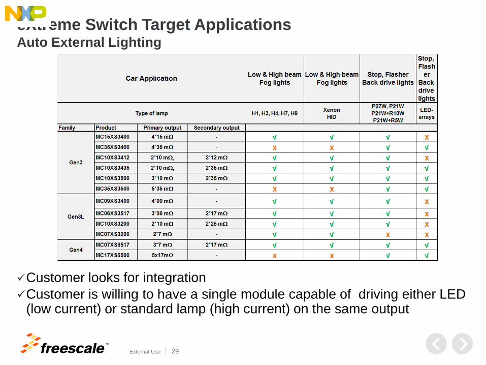
eXtreme Switch Target Applications Auto External Lighting
Customer looks for integration
Customer is willing to have a single module capable of driving either LED (low current) or standard lamp (high current) on the same output
TM
External Use 30
eXtreme Switch Available Documentation
• Datasheets
• Evaluation kit (EVB kit)
• Application notes:
− PQFN PCB guidelines
− EMC and fast transient pulses performance
− IBIS Model File for Dual 24V High Side
− Compact Thermal Model
− Robustness performance
− Training package
− …
• Tools
− Microsoft Excel® Thermal Calculator
− Cadence Orcad® Behavioral Models
• Reference designs

TM
External Use 31
Typical eSwitch EVB Kit Connected to SPIGEN Dongle
SPI communication
KITUSBSPIDGLEVME
KIT07XS6517EVB
12V Power supply
PC via USB
Load 1
Load 2
Load 3
Load 4
Load 5

TM
External Use 32
eXtreme Switch Available Documentation
• Datasheets
• Evaluation kit (EVB kit)
• Application notes:
− PQFN PCB guidelines
− EMC and fast transient pulses performance
− IBIS Model File for Dual 24V High Side
− Compact Thermal Model
− Robustness performance
− Training package
− …
• Tools
− Microsoft Excel® Thermal Calculator
− Cadence Orcad® Behavioral Models
• Reference designs

TM
External Use 33
Power Dissipation Calculator (Excel® based)

TM
External Use 34
Cadence Orcad ® Behavioral Model
• The behavioral model manages the electrical and thermal aspects concurrently. It allows evaluation of a device’s thermal performance under various conditions: − Supply voltage
− PCB design layout
− Ambient temperature
− eXtreme Switch device type changes
• Parametric range steps (over-current level, under-voltage threshold)
• The prediction of junction temperature elevation is based on computing transient power dissipation on dedicated channel. The reciprocal influence of junction temperature and on-state resistance of channel is modeled.
TM
External Use 35
eXtreme Switch Available Documentation
• Datasheets
• Evaluation kit (EVB kit)
• Application notes:
− PQFN PCB guidelines
− EMC and fast transient pulses performance
− IBIS Model File for Dual 24V High Side
− Compact Thermal Model
− Robustness performance
− Training package
− …
• Tools
− Microsoft Excel® Thermal Calculator
− Cadence Orcad® Behavioral Models
• Reference designs

TM
External Use 36
24V Reference Design Board

TM
External Use 37
Gen4 Reference Design Board
RefDesign Board
D17T07D17T07
P17 P17
RS
23
2C
AN
LabView
PC Interface
Vpwr
GND
CH10
CH11
CH12
CH13
CH14
UART
LIN
SP
I
a11
a22
3a3
4a4
b1
b2
b3
b4
5
6
7
8
Vcc1
0
GND
0
MC9S12XEP
V+
Vout
C+
GND
C-
MC33903
CH30
CH31
CH32
CH33
CH34
CH20
CH21
CH22
CH23
CH24
CH40
CH41
CH42
CH43
CH44
Loads (Bulbs, LED, HID)

TM
External Use 38
36V eXtreme Switch Analog Tower System
Supported Software Design Resource: Processor Expert
(MCU Driver Suite)
Interact, Explore, Create
with Tower Geeks Online Community
(www.towergeeks.org)
Available Sept. 2014

TM
External Use 39
Session Review/ Wrap-up

TM
External Use 40
Benefits of eXtreme Switches
Provide robust design, intelligence and safety
needed for 24V/12V applications
Increase integration to provide lighter, smaller
systems
Provide programmability and flexibility needed to
control all aspects of loads
Robust Design Increased Integration Flexibility
For automotive and industrial applications
SPI Fault Mgmt.
Simplified Software

TM
External Use 41
For Additional Information
Freescale’s website http://www.freescale.com/ Freescale’s analog website (useful PDFs plus links to other sites) http://www.freescale.com/webapp/sps/site/homepage.jsp?code=ANALOGHOME
About Freescale Analog Analog Technology Brochure (pdf) Analog Packaging Brochure (pdf) Analog Applications Brochure (pdf) Automotive Solutions Brochure (pdf) Analog Selector Guide (pdf) Automotive Selector Guide (pdf) SafeAssure Functional Safety Thermal Analysis of Semiconductor Systems (pdf)
High side switches, including eSwitches (parametric search & datasheets) http://www.freescale.com/webapp/sps/site/taxonomy.jsp?nodeId=01435979968459 Analog Toolbox (evaluation kits, SPIGEN software, reference designs) http://www.freescale.com/webapp/sps/site/overview.jsp?code=ANALOGTOOLBOX&uc=true&l
ang_cd=en SPI Generator (SPIGen) Software http://www.freescale.com/webapp/sps/site/prod_summary.jsp?code=SPIGEN

TM
External Use 42
Q&A Thank you for your attention

TM
© 2014 Freescale Semiconductor, Inc. | External Use
www.Freescale.com
TM
External Use 44
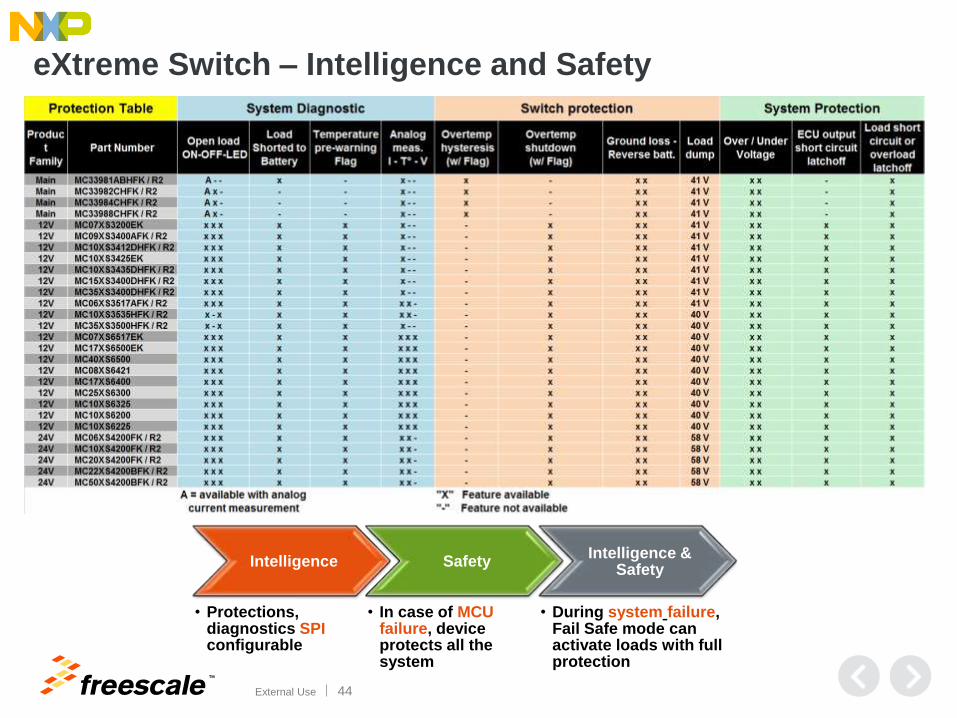
Intelligence
• Protections, diagnostics SPI configurable
Safety
• In case of MCU failure, device protects all the system
Intelligence & Safety
• During system failure, Fail Safe mode can activate loads with full protection
eXtreme Switch – Intelligence and Safety

TM
© 2014 Freescale Semiconductor, Inc. | External Use
www.Freescale.com