high reliability low loss coaxial cable assemblies … iss 4.pdf · real view on smp lock straight...
TRANSCRIPT

USER HANDBOOK REF. : RAD-GEN-CSHF.UHD DATE: March 13th, 19
ED/REV: 4/-
PAGE : 1/12
TITLE
HIGH RELIABILITY
LOW LOSS COAXIAL
CABLE ASSEMBLIES __________
USER HANDBOOK
WRITTEN BY RESPONSIBILITY DATE SIGNATURE
M. OJEDA
SPACE MARKETING ASSISTANT
13/03/2019
VERIFIED BY
S. POIZAT SPACE PROJECT MANAGER 13/03/2019
APPROVED BY
C. DASPRES SPACE QUALITY MANAGER
13/03/2019

USER HANDBOOK REF. : RAD-GEN-CSHF.UHD DATE: March 13th, 19
ED/REV: 4/-
PAGE : 2/12
DOCUMENTATION CHANGE NOTICE
REVISION OR
ISSUE
DATE CHANGE
1 -
1 A
2 -
2 A
3 -
4 -
04/11/2004
20/01/2005
17/06/2008
09/11/2010
22/06/2016
13/03/2019
Creation Cancelled SHF2.4MS and SHF3MS in the tables Updated with SHF2.4MS and SHF3MS in the tables. Updated to add note on the marking sleeves Updated to have only an English version Updated to add more information for SMP Lock cable assemblies

USER HANDBOOK REF. : RAD-GEN-CSHF.UHD DATE: March 13th, 19
ED/REV: 4/-
PAGE : 3/12
TABLE OF CONTENTS
1. OBJECT .................................................................................................... 4
2. CARE AND HANDLING ....................................................................... 4
3. BEND RADIUS OF CABLE ASSEMBLIES ........................................ 5
4. COUPLING TORQUE OF MATING CONNECTORS ..................... 5
5. MATING / UNMATING THE CONNECTORS SMP LOCK ........... 6
6. BENDING DISTANCE OF CABLE / CONNECTOR ...................... 11
7. NOTE ON THE MARKING SLEEVES ............................................. 12
8. CLAMPING METHODS OF CABLE ASSEMBLIES ..................... 12

USER HANDBOOK REF. : RAD-GEN-CSHF.UHD DATE: March 13th, 19
ED/REV: 4/-
PAGE : 4/12
1. OBJECT
This document gives the mounting recommendations applicable to any type of SHF cable assembly on the equipment of satellites in order to preserve the whole of their initial characteristics.
2. CARE AND HANDLING
The SHF cable assemblies have high electrical performances, any mistake in handling methods can generate irremediable degradations of performances
The cable assembly should not have blows, deformations, flat areas or other defects visible with naked eyes.
Before integration the interface of the connector will be free from all detachable particles, or pollution. The area of link between cable and connector protected by a heat-shrinkable sleeve shall not be subjected to abnormal stress. A light torsion of the cable is authorized within the limit of the values given in the table here-after.
The technical data sheets of the cable assemblies or the table 1 below specify 2 values of bending radius of the cable, namely:
• Static bend radius o It authorizes the bending only once, the straightened of the cable is not allowed.
• Dynamic bend radius o It authorizes 5 bending / unbending in the same zone of the cable without any degradation
of its performances.

USER HANDBOOK REF. : RAD-GEN-CSHF.UHD DATE: March 13th, 19
ED/REV: 4/-
PAGE : 5/12
For swept versions: The swept at the extremity of the cable assembly shall not be used to maintain it manually or to block its rotation during the mating or unmating of the connector on the equipment. Indeed, there is a risk of deformation of the swept. However a modification of the angle of approximately + or - 5° is acceptable during integration phase. The assembly of the connectors on the equipment shall be carried out using 2 keys, one with a torque wrench regulated with the value requested in the Technical Data Sheets or the table 2 to ensure the locking of the coupling nut, the other placed on the flats of the back of the connector to avoid its rotation.
3. BEND RADIUS OF CABLE ASSEMBLIES
4. COUPLING TORQUE OF MATING CONNECTORS
SMA SMA2.9 TNC SMP/SMP LOCK 80 -120 N.cm 80-115 N.cm 265 N.cm N.A.
SHF 2.4 MS SHF 3MS SHF 4.8MS SHF5MS SHF 8MS
Minimum static bend radius (mm) 15 15 25 25 40
Minimum dynamic bend radius (mm) 20 25 50 50 80
Torsion per meter of cable ± 90°
TABLE 1
TABLE 2

USER HANDBOOK REF. : RAD-GEN-CSHF.UHD DATE: March 13th, 19
ED/REV: 4/-
PAGE : 6/12
5. MATING / UNMATING THE CONNECTORS SMP LOCK
FOR SMP LOCK STRAIGHT AND RIGHT ANGLE CONNECTOR: Recommended tool: R282.868.290 to plug and to lock the connector (can also be plugged manually) R282.868.330 to unlock and to unplug the connector (to unplug manually is not recommended, risk to damage the cable at the rear of the connector.
SMP LOCK STRAIGHT: SMP LOCK RIGHT ANGLE:
WARNING: It is forbidden to push or pull the cable manually at the rear of the connector to plug or unplug the connector.
Face plane for pluging the connector
Groove for : • locking (nut) • unlocking (nut) • Disconnect the connector
Prohibited area to push or pull the cable manually
SMPL
SMPL

USER HANDBOOK REF. : RAD-GEN-CSHF.UHD DATE: March 13th, 19
ED/REV: 4/-
PAGE : 7/12
To plug: with Tool n°282.868.290
To Lock: with Tool n°282.868.290
To connect the connector (can also be plugged manually)
Lock the nut on the SMP Lock receptacle.

USER HANDBOOK REF. : RAD-GEN-CSHF.UHD DATE: March 13th, 19
ED/REV: 4/-
PAGE : 8/12
To Unlock and to unplug: with Tool n°282.868.290
To Unlock and to unplug within a limited area: with Tool n°282.868.330
1st step: Positioning the tool into the SMP groove
2nd step: Push at the stop position (flange)
1- Unlock the nut 2- Disconnect the connector

USER HANDBOOK REF. : RAD-GEN-CSHF.UHD DATE: March 13th, 19
ED/REV: 4/-
PAGE : 9/12
3rd step: And press more to unplug the connector
LOCKED / UNLOCKED POSITION
SMP Lock connector in UNLOCKED position
Real view on SMP Lock Straight Real view on SMP Lock Right Angle
USER HANDBOOK REF. : RAD-GEN-CSHF.UHD DATE: March 13th, 19
ED/REV: 4/-
PAGE : 10/12
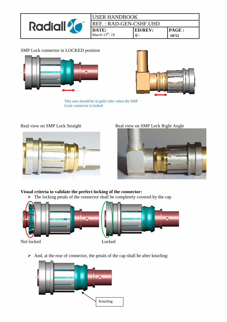
SMP Lock connector in LOCKED position
Real view on SMP Lock Straight Real view on SMP Lock Right Angle
Visual criteria to validate the perfect locking of the connector: The locking petals of the connector shall be completely covered by the cap
Not locked Locked And, at the rear of connector, the petals of the cap shall be after knurling:
This area should be in gold color when the SMP Lock connector is locked
Knurling
USER HANDBOOK REF. : RAD-GEN-CSHF.UHD DATE: March 13th, 19
ED/REV: 4/-
PAGE : 11/12
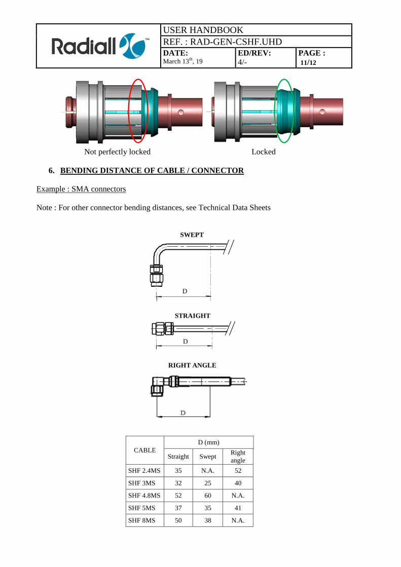
Not perfectly locked Locked
6. BENDING DISTANCE OF CABLE / CONNECTOR Example : SMA connectors Note : For other connector bending distances, see Technical Data Sheets
CABLE D (mm)
Straight Swept Right angle
SHF 2.4MS 35 N.A. 52
SHF 3MS 32 25 40
SHF 4.8MS 52 60 N.A.
SHF 5MS 37 35 41
SHF 8MS 50 38 N.A.
D
D
SWEPT
STRAIGHT
RIGHT ANGLE
USER HANDBOOK REF. : RAD-GEN-CSHF.UHD DATE: March 13th, 19
ED/REV: 4/-
PAGE : 12/12
7. NOTE ON THE MARKING SLEEVES
1ST CASE : CABLE ASSEMBLY WITH TWO MARKING SLEEVES AT EACH END In case there are only two marking sleeves (at each end of the cable assembly), these sleeves are fixed and should not move. 2ND CASE : CABLE ASSEMBLY WITH THREE MARKING SLEEVES In case there are three marking sleeves (one at each end of the cable assembly and a third at the middle), the two marking sleeves at each end are fixed and could not move. The marking sleeve on the middle is free to be able to move it along the cable in function of the fixing points on the equipment. Radiall installs three marking sleeves when there is a special marking required by the customer: a reference of the cable and special marking for each port of the cable assembly. The customer can shrink the middle sleeves if he wishes. To shrink the marking sleeve, use a hot air generator fitted with an adaptor on the end. When the new sleeve is placed at the right position on the cable, set the hot air generator thermostat between 150°C to 160°C maximum. The thermal sleeve should be shrinked homogenously along the cable. Check if it is possible to rotate the thermal sleeve around the cable. If yes, please heat again. If no, the shrinking of sleeve is good.
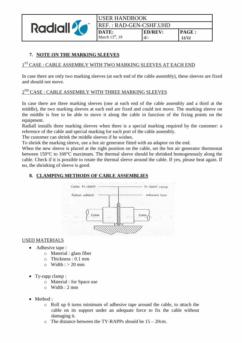
8. CLAMPING METHODS OF CABLE ASSEMBLIES
USED MATERIALS
• Adhesive tape : o Material : glass fiber o Thickness : 0.1 mm o Width : > 20 mm
• Ty-rapp clamp :
o Material : for Space use o Width : 2 mm
• Method :
o Roll up 6 turns minimum of adhesive tape around the cable, to attach the cable on its support under an adequate force to fix the cable without damaging it.
o The distance between the TY-RAPPs should be 15 – 20cm.