high-pw~er. · uy -classifi 2 1. "• link a links i incc .. role wo rol.... ol. .. wt ¢r s...
TRANSCRIPT

NMAB-29
JUL 192
High-Pw~er.
N M DIOYBARDA
A T IOA RSAR CUNINAINL CDM O CECE-AINA CDMYO NINERN

UnclassifiedSecufty Clasmificatioan ...
DOCUMENT CONTROLD6ATA---R & 0_(8eiurity imel ati let i af . i. m feemea~ adan noainuxt be epaterd when the ovurall report Is ilissitiedj
0. ORIGINATING ACTIVITY,(Col/pote am aM) Z. REPORT SECtJPITYCLA*SIPICATON
National Materials Advisory Board Ad Hoc UnclassifiedCommittee on High-Power Infrared-Laser b. GOUPWindows
3. REPORT TITLE
-HIGH-POWER IN#RARED-LASER WINDOWS
4. OESCRIPTIVE NOTES (TJIW efwig otEhwhive aeo&
Final Report -... .... . ..... ..$. AUTHIORtIS ( Iftaimme, modw fnllie, late A.)
National Materials Advisory Board Ad Hoc Committee on High-Powerinfrared-Laser Materials
S. REPORT OATE 70. TOTAL-NO. OF PAGES 1.*NO. or mRE"July 1972 168 T 140
".-CONTRACT Om BRANT NO, a. ORIGINATOR'S RCPo nT NUMBERISI
DA49-083 OSA 3131 NMAB-2926. P IOJACT NO.
C, b. OT4ER REPORT NOIS)(AflOYUIetlWnuMbQS 11tupYbe aailtnOdthi.tpoef)
10. OISTRIBUTION STATEMN T
This distribution has been approved for public release and sale;its distribution is unlimited.
It. SUPPLEMENTARY NOTES Ii. SPONSORING MILITARY ACTIVITY
None Department of Defense
I*. A§STRAC T The successful development of powerful infrared (IR) lasers,notably various types of CO2 lasers and certain chemical lasers, duri gthe past five years has opened up many applications for IR-laser beamRequirements exist for the creation and transmission of high-powerdiffraction-limited-infrared beams. Most efforts have so far beendirected toward the construction of IR lasers for the generation ofhigh-power radiation. No comparable effort was devoted to the speciamaterials problems which arise in the case of high-power transmission,The report of the Committee reviews in detail the state of the art anproblems presented by each of the seven subject areas into which thefield could be divided. These are: Propagation of IR Radiation inWindow Materials; Fundamental Absorption Mechanisms; ExperimentalAspects in the Characterization of High-Power IR-Window Materials;Single Crystal II-VI, III-V, and IV IR-Window Materials; ChalcogenideGlass IR-Window Materials; and Polycrystalline IR-Window Materials.The Committee draws several conclusions in each of these areas andrecommends in the report various research and development programsfor influencing the choice and criteria for window materials and foradvancing materials science in ths field.
DD IN.J14 73 UnclassifiedSecurity el stiriction

uy -classifi
21. "• LINK A LINKS i INCC ..
ROLE WO ROL.... ..OL. Wt
¢rS Chemical Lasers
CO2 Lasers
10.6Mm and 2-6Mm Wavelength Lasers
Infrared-Laser Windows
Propagation of IR Radiation
Absorption Mechanisms
Extrinsic
Intrinsic
Coatings
Experimental Aspects
Ionic Crystals
II-VI, Ill-V, and IV Semi-
conductor Crystals
Chalcogenide Glasses
Glass Ceramics
Scala-up
Polycysitalline Materials
UnclassifiedSecurity Classification

-~~ I- --,-~
HIGH'-POWER INFRARED-LASER WINDOWS
Report of
The Ad HOC Committee on
High-Power Infrar.ed"Laser-Windows
National Materials Advisory Board
Division of Engineering -National Research Council
L7., U.,
Publication NMAB-292
National Academy of Sciences - National Academy of Engineering
2101 Constitution Ave., N.W.
~Washington, D.C. 20418
~July 1972
' //

II
NOTICE
The study reported herein was undertaken under the aegis ofthe National Research Council with the express approval of theGoverning Board of the NRC. Such approval indicated that theBoard considered that the problem is of national significance;that elucidation or solution of the problem required scientificor technical competence and that the resources of NRC were par-ticularly suitable to the conduct of the project. The institu-tional responsibilities of the NRC were then discharged in thefollowing manner:
The members of the study committee were selected for theirindividual scholarly competence and judgment with due consid-eration for the balance and breadth of disciplines. Responsi-bility for all aspects of this report rests with the studycommittee, to whom sincere appreciation is expressed.
Although the reports of our study committees are not suib-mitted for approvai to the Academy membership or to the Council,each report is reviewedd by a second group of appropriatelyqualified individuals according to procedures established andmonitored by the Academy's Report Review Committee. Suchreviews are intended to determine, inter alia, whether themajor questions and relevant points of view have been addressedand whether the reported findings, conclusions, and recommen-dations arose from the available data and information. Distri-bution of the report is approved, by the President, only aftersatisfactory completioh 'of this review process.
This study by the National Materials Advisory Board wasconducted under Contract No; DA-49-083 OSA-3131 with theDepartment of Defense.
Members of the National Materials Advisory Board study groupsserve as individuals contributing their personal knowledge andjudgments and not as representatives of any organization inwhich they are employed or with which they may be associated.
The quantitative data published in this report are intendedonly to illustrate the scope and substance of information con-sidered in the study and should not be used for any otherpurpose, such as in specifications or in design, unless sostated.
Requests for permission to reproduce this report in whole or inpart should be addressed to the National Materials Advisory Board.
For sale by the National Technical Information Servige, Spring-field, Virginia 22151. Price $3.00 (Paper), $0.65 (Microfiche).

iii
NATIONAL MATERIALS ADVISORY BOARD
THE AD HOC COMMITTEE ON HIGH-POWER INFRARED-LASER WINDOWS
Chairman: Nicolaas Bloembergen, Gordon McKay Professorof Applied Physics, Division of Engineering andApplied Physics, Harvard University, PierceHall, Cambridge, Massachusetts 021.38
Members: Robert Willis Hellwarth, Professor of Physicsand Electrical Engineering, Seaver ScienceCenter, University of Southern California,University Park, Los Angeles, California 90007
Paul Leon Kelley, Massachusetts Institute ofTechnology, Lincoln Laboratories, Lexington,Massachusetts 02173
Pedro B. de Macedo, Professor, ChemicalEngineerir'- and Materials Sciences, The CatholicUniversity, 620 Michigan Ave., N.E., Washington,D.C. 20017
Marshall S. Sparks, XONICS, 6837 Hayvenhurst Ave.,Van Nuys, California 91406
LeGrand G. Van Uitert, Member, Technical Staff,Bell Laboratories, 600 Mountain Ave., MurrayNill, New Jersey 07974
Thomas Vasilos, Manager, Materials SciencesDepartment, Avco Space Systems Division, AvcoCorp., Lowell Industrial Park, Lowell,Massachusetts 01851
NMAB Staff: Donald G. Groves, Staff Engineer, NationalMaterials Advisory Board, National ResearchCouncil, National Academy of Sciences, NationalAcademy of Engineering, 2101 Constitution Ave.,N.W., Washington, D.C. 20418

iv
LIAISON REPRESENTATIVES
Department of Defense:
Dr. C. Martin Stickley, Deputy Director for Materials Sciences,Advanced Research Projects Agency, 1400 Wilson Blvd.,Arlington, Virginia 22209
Department of the Army:
Dr. Jefferson S. Bennett, Physical Sciences Directorate,AMSMI-RRE, Bldg. #5429, U.S. Army Missile Command, RedstoneArsenal, Huntsville, Alabama 35809
Dr. R. Nathan Katz, Chief, Ceramics Division, U.S. ArmyMaterials & Mechanics Research Center, Watertown,Massachusetts 02172
Department of the Navy:
Dr. Arthur M. Diness, Code 471, Office of Naval Research,Department of the Navy, Ballston Tower #1, 800 North Quincy St.,Arlington, Virginia 22217
Dr. Van 0. Nicolai, Code 471, Office of Naval Research,Department of the Navy, Ballston Tower #1, 800 North Quincy St.,Arlington, Virginia 22217
Department of the Air Force:
Dr. Vincent L. Donlan, Air Force Materials Laboratory,Code: AFML/LP, Wright-Patterson Air Force Base, Dayton,Ohio 45433
Mr. Charles E. Ryan, Solid State Sciences Laboratory, AirForce Cambridge Research Laboratories, L. G. Hanscom Field,Bedford, Massachusetts 01730
Capt. Harry V. Winsor, Laser Division, Air Force WeaponsLaboratory (LRO), Kirtland Air Force Base, Kirtland,New Mexico 87117

v
ACKNOWLEDGMENTS
In addition to the members and liaison represen-
tatives who participated in this National Materials Advisory
Board study on High-Power Infrared-Laser Windows, a large
number of distinguished people from many fields also made
very substantial contributions to thiR report. Some of
these were professional colleagues of the Committee partic-
ipants, who served unofficially, lending their ideas, advice,
and assistance to-various portions of the work. Others,
including
Mr. Charles F. Bersch, Naval Air Systems Command,
Washington, D.C.
Dr. Morris Braunstein, Hughes Research Laboratories,Malibu, California
Dr. Joseph Burke, General Electric Co., Schenectady,New York
Prof. Elias Burstein, University of Pennsylvania,Philadelphia, Pennsylvania
Dr. Peter 0. Clark, Hughes Research Laboratories,Malibu, California
Prof. Robert Coble, Massachusetts Institute ofTechnology, Cambridge, Massachusetts
Dr. Charles Greskovitch, General Electric Co.,Schenectady, New York
Dr. Ricardo C. Pastor, Hughes Research Laboratories,Malibu, California
Dr. Douglas A. Pinnow, Bell Laboratories, Murray Hill,New Jersey
Prof. Robert 0. Pohl, Cornell University, Ithaca,New York
Dr. Roy Rice, Naval Research Laboratory, Washington, D.C.

vi
Dr. Peter A. Young, Police Scientific DevelopmentBranch, Woodcock Hill, Herts, England
were official guests of the Committee and contributed
tutorial-type presentations at varioue meetings. The
untiring efforts of Mr. Donald G. Groves, the Nnttonal
Materials Advisory Board Staff Engineer for the Committee,
who helped the Committee in numerous ways, are gratefully
acknowledged.
We express here our indebtedness to all these
people for their invaluable services to the Committee on
High-Power Infrared-Laser Windows.
Nicolaas Bloembergen, ChairmanNational Materials Advisory BoardAd Hoc Committee on High-PowerInfrared-Laser Windows
i

vii
CONTENTS
page
ACKNOWLEDGMENTS ................. v
I. INTRODUCTION AND CHARGE TO THECOMMITTEE. . . . . . . . . . . . . 1
II. SUMMARY OF COMMITTEE CONCLUSIONSAND RECOMMENDATIONS. . . . . . . . 5
III. PROPAGATION OF INFRARED RADIATIONIN WINDOW MATERIALS. . . . . . . . 17
IV. FUNDAMENTAL ABSORPTION MECHANISMS . 37
V. EXPERIMENTAL ASPECTS IN THE CHARAC-TERIZATION OF HIGH-POWER INFRARED-WINDOW MATERIALS ......... 55
VI. SINGLE CRYSTAL ALKALI-HALIDEINFRARED-WINDOW MATERIALS. . . . . 65
VII. SINGLE CRYSTAL II-VI, III-V, AND IVINFRARED-WINDOW MATERIALS. . . . . 83
VIII. CHALCOGENIDE GLASS INFRARED-WINDOW MATERIALS . . . . . . . .. 97
IX. POLYCRYSTALLINE INFRARED-WINDOWMATERIALS ............. 1 17

I. INTRODUCTION AND CHARGE TO THE COMMITTEE
The successful development of powerful infrared
(IR) lasers, notably various types of CO lasers and certain2
chemical lasers, during the past five years has opened up
many applications for IR-laser beams. Requirements exist
for the creation and transmission of high-power diffraction-
limited IR beams. Most efforts have so far been directed
toward the construction of IR lasers for the generation of
high-power radiation. No comparable effort has been made
to solve the special materials problems that arise in con-
junction with high-power transmission. Components that
are capable of transmitting low-power IR beams without
optical degradation present serious limitations at high-
power levels. The handling of high-power beams requires
nearly lossless reflection from mirrors and nearly reflec-
tionless and lossless transmission through windows.
Materials damage by laser beams with high-flux density is
well known, but optical distortion of the beam during
passage through a window usually becomes unacceptable well
before the window fails mechanically. The main cause of
this distortion has been identified as heating by a small
residual absorptivity of the transparent material exposed
to the high-power beam.
Consequently, several research programs were
undertaken duiing the past few years to develop high-power-
IR windows. Since the development of new materials is a
costly process and since no known and available material
could meet the simultaneous requirements of size (diameters

/
-2-
in excess of 10 cm) and of good mechanical and optical-
properties at high-power levels, it appeared that a syste-
matic review of various materials-research efforts to
develop high-power IR windows would be advisable. Such a
study could also identify the most promising materials
and, possibly, make recommendations for the materials-
research and-development program for the next few yeare.
With this background, the Advanced Research
Projects Agency (ARPA) requested that the National Materials
Advisory Board (NMAB) of the National Academy of Sciences-
National Research Council initiate an appropriate ad hoc
committee study to explore the various IR window materials
problems for high-power lasers, such as CO2. CO, and
chemical lasers, and to recommend programs directed to
their solution. More specifically, the task of this study
for the Department of Defense was to assess the importance
of factors deleterious to the transmission of high-power
diffractiozi-limited laser beams with wavelengths between
2 and 6 micrometers (pm) and near 10.6Mm through solid
windows, to assess the importance of various possible
absorption mechanisms, and to make recommendations for the
most suitable composition and for-a of materials for these
windows.
The National Materials Advisory Board accepted
the charge and an ad hoc Committee on High-Power Infrared-
Laser Windows was established in June 1971. The full
committee, consisting of seven members plu? eight liaison
representatives from the Army, Navy, Air Force, and ARPA,
held five formal two-day meetings during the period from
!I
-3-
September 1971 through April 1972. In addition, there
were several smaller sessions involving various groups of
committee members. At the full committee meetings, pre-
sentations Were made by leading research experts in
government, university, and industrial laboratories. This
report contains the results of the deliberations of the
committee members, liaison representatives, and invited
speakers.
The major findings of this study are summarized
in the next chapter. The remaining chapters review, in
detail, the state of the art and the problems presented
by each of seven subject areas into which the field could
be divided. These are:
Propagation of Infrared Radiation in Window Materials
Fundamental Absorption Mechanisms
Experimental Aspects in the Characterization of
High-Power Infrared-Laser-Window Materials
Single Crystal Alkali-Halide Infrared-Window-Materials
Single Crystal II-VI, III-V, and IV Infrared-Window
Materials
Chalcogenide Glass Infrared-Window Materials
Polycrystalline Infrared-Window Materials
There are numerous other engineering problems
in the window design besides the development of suitable
window materials. Mechanical details of mounting, the
manner of cooling the window surfaces and rims, the pro-
tection of the optical windows during periods when no
laser beam is transmitted, the question of segmenting the

-4-
window area by using a honeycomb frame with smaller and
thinner window panes, aerodynamic loading, the maintenance
of a controlled-temperature profile, the single pulse,
pulse train, of the quasi-continuous mode of power trans-
mission: these are all important aspects of the high-
power ZR-laser-window problem. The scope of the present
report, however, is limited to window materials. Over-all
system design and engineering consideratioi~s are not
included, although it will be pointed out that certain
materials may be better suited for or have special advan-
tages in certain modes of window design and operation.
Conversely, results of engineering studies will influence
the choice and criteria for window materials.

-5--L
II. SUMMARY OF COMMITTEECONCLUSIONS AND RECOMMENDATIONS
In this chapter the main conclusions and recom-
mendations of the report are summarized. This summary is
based on the detailed discussions in Chapters III through IX,
which should be consulted for both supporting evidence and
the general context in which these conclusions and recom-
mendations should be viewed.
Conclusion 1
The basic theories for propagation of high-power
IR-laser beams through window materials are well understood.
The effects of thermal lensing distort the optical quality
of the beam and this effect usually occurs before material
damage of the window sets in. In either case the basic
criteria for the selection of suitable window materials
are, therefore, well established. An optical figure of
merit has been defined which is best for materials with
the lowest absorptivity and lower thermal coefficient of
the index of refraction. Unfortunately, the classes of
materials with the best optical figure of merit often have
less desirable mechanical, chemical, and thermal properties
so that trade-offs must be made.
Conclusion 2
No material available in its present form is
suitable for the fabrication of a high-power IR-laser
window, but the prospects that such a material may be

-6-
developed within two years are encouraging. Since material
development is expensive, funds will be saved if large-
scale-crystal growth, processing, and fabrication is avoided
until the required optical figure of merit and acceptable
mechanical and chemical properties have been demonstrated
on small test samples.
Conclusion 3
High-power IR-laser-window materials will need
anti-reflection (AR) coatings. in addition, several of the
more promising materials will need protective coatings
against the deleterious effects of the atmosphere, especially
of water vapor. Very little work has been done on such
coatings in the IR regions of interest, near 10.6Mm and
between 2-6Mm. The feasibility of such coatings should
first be established n small-scale samples. The absorp-
tion in coatings and surface layers must also be measured
before scale-up in fabrication is attempted.
Conclusion 4
Many optical, mechanical, chemical, and thermal
properties of a material must be monitored during the
stages of the development process. Most of these are
routine but the measurement of low absorptivity requires a
specially constructed calorimeter arrangement, and the
determination of small- and large-angle scattering and
optical distortion requires special optical bench arrange-
ments. Preliminary testing may de done conveniently with

-7-
visible light if the materials are also transparent in
that region. Access to infrared optical-test facilities
is essential for development of IR-laser-window materials.
Conclusion 5
Materials with the lowest demonstrated optical
absorptivity and the highest demonstrated optical figure
of merit at 10.6Mm may be found among the alkali ha.ides,
notably KBr. The pure crystal is, however, mechanically
weak but can be strengthened by about an order of magnitude2+
by the addition of Sr ions width an unknown effect on the
absorptivity. The crystal needs a protective coating
against the atmosphere but successful preliminary tests
with coatings of As2S 3 glass have been reported. It has
been demonstrated that alkali-halide crystals can be grown
in large sizes.
Conclusion 6
The TA(Br,I) materials are not hygroscopic and
do not need a protective coating. They should have a low-
intrinsic absorptivity but the lowest value reported is-3-1
= 5x10 3 cm"1 To date, howevr, no special effort has
been made to purify the material. In its polycrystalline
sintered form, the material has attractive mechanical
properties. The temperature coefficient of the index is
large and the figure of merit is lower than for the alkali
halides, but it may still he acceptable in well-cooled
window configurations.
-8-
Conclusion 7
In the spectral region between 2-614m, the
fluorides BaF2 and SrF2 are serious candidates for window
materials. They are not hygroscopic, have a high optical
figure-of merit, and have better mechanical properties
than the alikali halides. Anti-reflection coatings mst be
developed. Sapphire, MgO, and certain semiconductors
should also be considered in this wavelength region.
Conclusion 8
The most promising semiconductor materials for
windows at 10.6pm are Ge, GaAs, ZnSe, and CdTe. To avoid
excessive absorption by free carriers, germanium must be
in an ultrapure form for which the free-carrier contribution
to the absorption coefficient is expected to be about 10
cm . The values of A so far obtained for ZnSe, GaAs, and
CdTe are not low enough for an acceptable window material.
The intrinsic value of 0 could well be lower and may be
attainable by further purification. The questions of
growing samples in large sizes and preparing anti-reflection
coatings are unsolved.
Conclusion 9
Chalcogenide glasses have excellent mechanical
properties, are resistant to the atmosphere, and are
obtainable in large pieces. However, their optical figure
of merit demonstrated to date is inadequate for bulk
window material. The abZ.'rptivity is fairly high due to

-9-
oxygen impurities and possibly multiphonon absorption.
Compositional changes and control of oxygen content may
improve 'he situation. These glasses have shown promise
for protective and anti-reflective coatings.
Conclusion 10
The outlook for developing polycrystalline
materiale of required optical quality and figure of merit
is not bright by particulate consolidation method, but
chemical vapor deposition and casting processes have shown
promise. Recrystallization by press forging and extrusion
can substantially improve mechanical properties. There is
some indication that this can be acccmplished without
unacceptable degradation of the optical properties.
Conclusion 11
Present knowledge of bulk absorptivities in pure
substances is sufficient to provide guidelines for the
present selection of candidates for window materials.
For long-range progress it is, however, important to refine
our understanding of the theory of fundamental bulk and
surface absorption and of the role of free-carrier absorp-
tion, grain boundaries, and impurities. Further experi-
mental data on fundamental absorption edges are required
for many materials, and experimental data on surface
absorption and the influence of radiation damage are
needed.
-10-
Conclusion 12
In the case of extremely high-power-fluxdensities, exceeding 10 megawatts/cm2 , a variety of non-
linear effects, such as laser-induced self-focusing
breakdown and stimulated Brillouin scattering, may play a
role. Such power densities can occur in extremely short
pulses and are of interest for thermonuclear power genera-
tion. The nonlinear effects in the infrared are not
sufficiently understood.
Recommendations
Based on these conclusions, the following recom-
mendations, listed in their approximate order of priority,
are made. For a sustained effort, all should be implemented.
(Short-range effort means a 1- to 2-year period, while long-
range efforts are 2-5 years. Where a short-range effort
of 4 man-years is specified, this means 2 men for 2 years
or 4 men for 1 year. A man-ye&: corresponds roughly to an
expenditure of $50,000.)
Recommendation 1
A strong effort should be made to evaluate the
alkali-halide crystals as suitable window materials. The
system KBr:Sr or related systems are recommended for
intensive study. The following successive steps in a
short-term program are identified as needing immediate
attention:

- -1 7 - -- v- - -
I/
-11-
1) Purify KBr and SrBr2 and remove as far as possible
OH-, F', CA-, CN', etc.
2) Grow small size single crystals of KBr:Sr and
obtain the required mechanical strength and
optical properties.
3) Develop a protective (chalcogenide glass) and
anti-reflective coatings.
4) Fabricate and test small size coated windows
cut from crystals oriented in a <111> direction.
An effort of 6 man-years over the next 2 years
at an estimated cost of $300,000 is recommended,
Recommendation 2
The assessment of semiconductor material for
window applications should be continued. Primary attention
should be given to a continuation of chemical vapor deposi-
tion of ZnSe. Further work on germanium and high-resis-
tivity GaAs and further purification of ZnSe and CdTe is
also recommended. In addition, the fundamental absorption
edges and background absorptivities of many other substances
should be measured to assess their potential for window
application before embarking on a materials-development
program for those materials. The following program elements
are recommended:

)/
-12-
1) Continuation of the improvement of absorptivity
of ZnSe and CdTe, both in single crysta1 form
and by chemical vapor deposition techniques. A
total effort of 6 man-years over the next 2 years
is recommended at an estimated cost of $300,000.
2) Evaluation of the potential of ultrapure Ge.
3) A survey of general spectral absorption measure-
ments and determination of other physical properties
on a variety of available crystals, especially
GaAs, which may have sufficient transparency in
the infrared. An effort of 4 man-years over the
next 2 years is recommended at an estimated cost
of $200,000.
4) Development of anti-reflective coatings for
semiconductors.
Recommendation 3
It is recommended that a basic research program
be maintained in parallel with the window development
programs and research programs on specific materials men-
tioned in the other recommendations. The following parts
of a basic program should be carried out concurrently:
1) Basic theoretical and experimental studies of
fundamental absorption processes in pure bulk
crystals, at surfaces, and by imperfections and
conduction electrons. Ai effort of 3 man-years
over the next 2 years at an estimated cost of
$150,000 is recommended.

-13-
2) Basic experimental studies o± infrared nonlinear'
effects occurring at very high-flux deansities.
An effort of 3 man-years over the next 2 years
at a cost of $150,000 is recommended.
it should be kept in mind that the basic programs
have a long-range character and it is probably advisable to
extend them beyond the two-year period at a comparable
annual level of f-dnding.
Recommendation 4
Since the 2-6Am wavelength region is of consid-
erable future interest, a program should be initiated now
to develop suitable windows for this spectral region. It
is recommended that the initial program concentrate on the
materials SrF 2and BaF 2in the following steps:
1) Purify SrF 2and BaF2a
2 2
2) Grow small size single crystals and determine
mechanical and optical properties.
3) Develop anti-reflective (AR) coating.
4) Fabricate and test a small size coated window.
An effort of 5 man-years over the next 5 years
at an estimated cost of $250,000 is recommended.
Recommendation 5
The-absorption by surface layers and coatings
and the resistance of such layers to temperature rise and
mechanical deformation when exposed to high-power-IR fluxes
should receive more attention. The influence of ultraviolet
and nuclear radiation on the optical and mechanical proper-
ties of coatings and bulk materials must also be investi-
gated. The cost of these investigations is partly absorbed
in the cost estimates for the other recommendations. In
addition, an independent coating research program is
recommended at the rate of 1 man-year for 2 years at an
estimated cost of $100,000.
Recommendation 6
An effort should also be initiated immediately
to assess the suitability of TA(Br,I) as a window material.
The following steps in a short-term program are recommended:
1) Purify TLBr, TAI, and BaBr2.
2) Grow small size single crystals of TA(Br,I):Ba
and determine their mechanical and optical
properties.
3) Develop AR coating.
4) Fabricate a small size coated window and test
in a high-power beam at 10.6Mm.
An effort of 3 man-years over the next 2 years
at an estimated cost of $150,000 is recommended.
-15-
Recommendation 7
The method of recrystallization, for example by
press forging and extrusion, to improve mechanical proper-
ties of window materials with tolerable optical degradation,
should be further applied to single crystals of alkali
halides of low absorptivity. A 2 man-year effort over the
next 2 years is recommended at an estimated cost of
$100,000.
Recommendation 8
The assessment and improvement of chalcogenide
glasses as coatings and as bulk window materials should be
continued. Emphasis should be given to a reduction of
absorption due to oxygen impurity and other sources. Anti-
reflective coating for the glasses should also be developed.
An effort of 4 man-years over the next 2 years at an
estimated cost of $200,000 is recommended.
Recommendation 9
It is recommended that experimental facilities
to measure all pertinent optical, thermal, mechanical, and
chemical properties be closely integrated with each of the
development projects recommended above. Arrangements for
exchange of data and samples as well as access to testing
facilities and computational programs of other groups
should be improved.

-16-
Recommendation 10
If any of the development programs in the
previous recommendations have led to small size test
windows with acceptable characteristics, scale-up programs
should be started immediately on that particular window
material. The scale-up should not only involve the growing
of large crystals but also the cutting and polishing of
large windows and the application of coatings to large
surfaces. The scale-up operations will be expensive and
no estimates of cost, time, and manpower are given. Zt is
strongly recommended, however, that no premature scale-up
be attempted beyond the size needed to assess the required
properties.

77- -
III. PROPAGATION OF INFRARED RADIATION IN LASER WINDOWS
A. Introduction
There is steady progress in the development and
use of high-power lasers. As CW power and energy per
pulse increase, a class of problems is encountered which
is not found with low optical powers. Optically induced
changes in the propagation characteristics can take place.
These self-induced effects can occur in a variety of
places, for example: inside the optical gain medium, at
mirrors and windows, and in the medium intervening between
the laser source and the point where the radiation is to
be received (e.g., the atmosphere). Solid high-power-
laser windows are necessary to isolate different regions
through which the laser beam must propagate. Section B
of this chapter deals with what is believed to be the most
important propagation problem in nearly transparent high-
power-laser windows. Other problems will be considered
briefly at the end of the chapter.
B. Self-Induced Effects Due to Absorption
When electromagnetic radiation passes through
matter some portion is absorbed. The absorbed energy can
cause changes in the physical characteristics of the
material including its optical properties. If the radia-
tion flux is large enough, the material may undergo catas-
trophic changes such as melting or fracture. Due to the
energy deposited, the absorption constant can increase or
-18-
decrease and changes can occur in optical phase through
thermal expansion and changes in index of refraction. It
is the dependence of optical phase on the optical flux
that limits the amount of optical energy which may be
transmitted through a window, assuming that negligible
distortion in the optical wavefront is desired. Equiva-
lently, one can describe the optical phase changes as the
introduction of an aberrated lens into the beam. (--3)
This self-induced thermal lens effect can spread the far-
field beam pattern.
The conditions can be determined under which
phase-front distortions are severe enough to limit an
optical systems ability to send collimated beams of light
over large distances or to focus the radiation to high-
flux densities. A reasonable criterion for negligible
phase distortion is:
16 1nc _ 6Pn.c. I max, 4' (III-1)
where Upin.c. and Up.j are the noncorrectable (n.c.) phase
distortions at two arbitrary points in the beam profile.
That this criterion is not overly severe is evident from
the normal optical design criteria of 1/10 to 1/20 wave.
The phase change due to the presence of the window for a
cylindrically symmetric beam can be written -
c(r) = k dz In(r,z)- i}, (III-2)0

-19-
where k - 2n/k, X is the wavelength, z is the coordinate0
in the direction of propagation, r is the radial coordinate,
A is the thickness of the window, and n is the index of
refraction. The ronlinear phase change is expected to besmall compared to the normal linear optical change in
phase, so that
60(r) = k0 {(n o - 1) 68(r) +A6n(r)), (111-3)
where n' is the normal index of refraction of the window,0
A is the thickness, 68A(r) is the induced change in thick-
ness, and 6n(r) is the induced change in index of refrac-
tion averaged along the direction of propagation. Using
(IIl-i), (111-2), and (111-3), an approximate criterion for
aberrationless propagation through the window can be taken
to be+ , (111-4)
" +(no 8(n - 1)1L
where A£ = 61(r) - 6A(r 2 ) and An = On(r I ) - 6n(i'2).
r and r2 being a suitably chosen pair of radial coordinates
(e.g., the beam center and the l/e point in a Gaussian beam).
For simplicity the superscripts n.c. are suppressed. It is
useful to consider what occurs when the above criterion is
strongly violated. The deflection of a ray after passing
through the window is given by
r (r)e~) I (,z)- ]dzI" (I05

-20-
As an example, a sketch of the phase profile and deflectionis given in Figure 1 for a highly aberrated case. The ray
deflection in this case has a maximum at finite radius.
For this to occur, phase variations depending on powers of
the radial coordinate higher than quadratic must contribute
appreciably. In this case rays from different parts of the
beam (as it leaves the window) can reach the same point in
the far field and interfere either constructively or de-
structively. This leads to a series of aberration rings
and the far field intensity is degraded from the aber-
rationless dase. Figure 2 shows the aberration rings
produced in the conductive steady state for an argon laser
beam passing through lead glass.
The induced changes in phase arise from the
absorption of energy. Generally, this energy is rapidly
thermalized and can be considered to be heat. Therefore,
the effect of the deposition of heat on the optical
properties is considered. A linear dependence of 8n and
6A on temperature change and strain is assumed. There are
several time regimes of interest. The shortest time
regime occurs when the optical pulses are so short that
the system is far from stress-strain steady-state and
the index change is entirely a local phenomenon. An
intermediate regime occurs when the stress-strain steady-
state is reached but the thermal steady-state is not.
Finally, for sufficiently long times thermal conduction
becomes important in determining the temperature profile
and hence the index profile.

20 (a)
ANGULAR DEFLECTION e
0
rn
BEAM PHASE PROFILE
Fig~ure 1. Solid curve - representation of angular
deflection vs radial coordinate.
Dashed curve -beam phase profile.
il - - - -- -

20 (b)
Figure 2. Far-field pattern of 1 watt Argon laser beam
(4=0.488gm, initial i/e 2 radius = 0.1 mm,
initial beam slightly divergent) after passing through-1
1.2 cm of lead glass ($=0.20 cm ). The conductive steady
state has been reached. From F. W. Dabby, et al, Appl.
Phys. Letters 16, 362 (1970).

-21-
In the short-time regime, when ./v >>t, where vs 5
is the velocity of sound, and therefore thermal expansion
cannot occur, the criterion (111-4) becomes
l n l T < ,(111-6)BT p84~
where an/aT IP is the index change with temperature at
constant density, and AT = 6T(r1 ) - 6T(r 2).
In stress-strain steady-state a cylindrical beam
passing through a cylindrical window exhibits birefringence
between the azimuthal and radial directions. For this case,
the change in optical phase with temperature has been
estimated by Sparks (2)for a cylindrical slab window such
d>>A (d is the window diameter) using an approximate stress
distribution with the assumption of xrstrained edges. For
simplicity, average strain values in the two directions of
polarization are used here so that the effect of birefrin-
gence is eliminated. This does not mean, however, that
birefringence effects are unimportant, but rather that to
include these effects correctly is a problem too detailed
in scope for the present report. Furthermore, satisfying
the criteria developed here should, as can be seen from
more detailed analyses, also eliminate the birefringence
effects. With the above considerations in mind, the
criterion (111-4) becomes
6 A < (111-7)n6nATT <81
-22-
where
[n9nT T 3 4 1 ] (nol)a(l+v) (111-8)
where v is Poisson's ratio, P and P are strain-optic
coefficients, and o is the linear coefficient of thermal
expansion. The term in square brackets represents thechange in refractive index, while the last term is the
change in length. For some materials the temperature depen-
dence of the index of refraction is known under stress-free
conditions but P and P are unknown, in which case it is
necessary to replace 6 by an approximate value 6 ' wherenTnAT'whr
8T = n I=0 + (n- 1) (l+v) ,(II-9)
where 6n/bT J =0 is the temperature derivative of refrac-tive index found experimentally under stress-free conditions.
an/aT Ia=0 can be expressed as
3nBn bnI O (p + 2P )(k. (11l-10)
T 0-T I =-0 aT (P11 12
In some materials 6nT and 6 are both available. In
halogen compounds 6' may be as much as a factor of twonZ T
larger than 6nAT ' while for covalent materials the values6nT and 6n'T are very close.
Note that by replacing the inequality in (111-6)
and (111-7) by an equality and solving for AT we can obtain
an estimate of the temperature difference between two radial
points in the beam profile at which thermal-beam distortion

-23-
becomes appreciable. In addition to heating by the beam
itself, this temperature difference can occur because of
the environment in which the window is used.
In the majority of cases of interest, the time
constant for radial conduction is much longer than the
time duration of the laser radiation, so that radial con-
duction may be neglected. The radial temperature profile
therefore follows the beam profile. If the beam profile
is a Gaussian truncated at the l/e2 radius, the l/e
radius is a reasonable point at which to determine the
temperature rise with respect to the beam center. Also,
the quadratic phase term is assumed to be compensated for
by refocusing. (It is somewhat questionable whether any
compensation is possible in many practical situations;
however, the results which are obtained would be.changed
by numerical factors of the order of 2 to 4 by the inclu-
sion of the quadratic term or conversely by the incorpora-
tion in the system of a focus correction which minimizes
the over-all effect of window phase distortion. These
numerical factors will be indicated below.) With the
above considerations in mind, the temperature difference
is found to be given by
AT A T ,(III-ll)e 0
where AT is the temperature rise at the center of the0
beam. For the materials considered in this report,-6 -4
6n/6Tj and 6 T are in the range 2 x 10 - 2 x 10 /K,

-24-
so that from (111-6), (111-7), and (III-ll) it is seen that
LAT < 2-200 cm-K , (111-12)
0i
at losm, for distortionless propagation.
The temperature rise on the beam axis is given by
01I tAT ( -13)0 C
where B is the absorption constant, I is the central0intensity, C the heat capacity per unit volume, and tI is
a characteristic time. Surface absorption is included in
the distributed absorption as follows:
b+b12o+ (III-14)
where B° is the actual volume absorption, and b and b2are the fractional absorptions at the surfaces. This is,
of course, only an approximation; to obtain a more accurateresult, one must solve a difficult problem in thermal
stress and heat-transfer analysis. There can also be
serious breakdowns in the approximation if the surface
heating is large enough to cause deviations in the assumed
dependence of material properties on temperature change
and strain. If optical intensities are high enough,
surface damage can occur due to surface absorption.
For times short compared to the time for heat
transfer by conduction to the surface and subsequent
-25-
removal from the surface,
where t is the time elapsed from the onset of irradiation
of the window. For times long compared to the heat trans-
fer time,
t I t c + ts 8 (111-16)
where
t c 12 (111-17)c 3k
t CA (111-18)S h '
k is the thermal conductivity of the window, and h is the
surface heat-transfer coefficient.
Combining the above results, the following set
of criteria is obtained which, if satisfied, will allow
radiation to propagate undistorted through the window.
Region 1. (t < A/v s )n
I n 0=1$ t/C < ek/84A (111-19)6T, ~ 0

-26-
Region 2. (tc + t > t > l/vd/v
6 T t/C < eX/8. (111-20)nI 81~ 0t
Region 3. (t > t + t),c a
I6ntT I I(t + t s)/C < eX/8A, (1II-21)
where 6 is given by (111-8) or (111-9) and t and tnAT c s
are given by (111-17) and (111-18). Replacing the inequality
by an equality in (111-19) through (111-21) and solving for
1 0t (the energy per unit area) in (111-19) and (111-20) and
I (the intensity) in (111-21), we obtain values of energy
per unit area and intensity at which the thermal leps effect
becomes appreciable. These criteria would be more stringent
by about a factor of two if the quadratic term is uncompen-
sated. Using Spark's analysis, it is estimated that the
criteria could perhaps be a factor of four less stringent
if the over-all window phase distortions are compensated
for by focusing.
The thickness of the window, 2, is usually deter-
mined by the pressure differential which the window must
withstand (in the case of equalization of the average
pressure, pressure fluctuations or buffeting determine how
much pressure differential the window must withstand).
The criterion for the window not to undergo inelastic
change under a pressure difference Ap is
A > 0.56 ( , SF d, (111-22)Y

_ - "
-27-
where is the yield or rupture stress (whichever is
lower), d is the window diameter, and f is an engineeringsF
safety factor. The above condition can be combined with
(111-19) through (111-21) to obtain criteria, which depend
only on window diameter and material parameters, for the
capability of windows to transmit energy or power without
phase-front distortion. in this case for regions 1 and 2
there is a linear dependence of the energy transmitted on
window diameter.
The above calculations are for a single pulse.
It is relatively easy to use these results to analyze any
of the many situations which may be encountered in practice.
For example, for a single pulse it may be found that
t < ts + tc , but the average time between pulses (5b) in aCb
series of pulses may be such that 5, > ts + tc. In this
case the average power-handling capability could be tested
by (111-21), taking I as the average power.0
Several other detrimental effects induced by the
absorption of radiation from the beam have been considered. (4)
Thermal runaway, melting, and dissociation generally occur
at much higher temperatures than those which produce the
thermal lens effect. The criterion for thermally induced
inelastic changes not to occur is given by
AT < 2 /UE, (111-23)
where AT is the temperature rise in the center of the0

-/
-28-
window with respect to the edge, a is the linear coefficient
of thermal expansion, and E is Young's modulus. The cri-terion (111-23) can also be re-expressed in terms of pulse
energy or intensity using (111-12) and (111-14) or (111-15).
The inequality (111-23) can also be compared with the in-
equalities which result in combining (111-6) or (111-7)
with (III-11). For pure alkali-halide single crystals,
thermally induced inelastic change occurs for very small
temperature rises and these materials must be strengthened
as discussed in a subsequent section.
Absorptively induced damage at inclusions and
dielectric breakdown were discussed in the National(5)Materials Advisory Board Glass Laser Damage Report and
they are reconsidered briefly here. They can be considered
to be high-peak-power effects. The significance of inclu-
sion damage is strongly dependent on material preparation
and it is, therefure, difficult to make a priori predictions.
Generally, one would like to avoid these damage causing
inclusions by careful material. processing. A theory of
inclusion induced damage has been given. Dielectric
breakdown in alkali halides for 102 sec pules at 10.6gmoccurs at power densities in the vicinity of 10 watts/cm
At shorter wavelenqths, the power densities for breakdownshould be equal or higher.
C. Other Nonlinear Effects
Other detrimental nonlinear effects can occur
at high-optical intensities (> 106 watts/cm 2) such as

-29-
nonabsorptively induced refractive index changes leading
to self-focusing (5)and stimulated light scattering. Index
nonlinearities due to electrostriction and the electronic
Kerr effect are too small to cause significant phase dis-
tortion through a high-power-laser window at flux 4ensities11 2
of less than 10 watts/cm
Stimulated light scattering is also a possible
loss or damage mechanism in laser windows. Light scattering
would produce light traveling in the plane of the window
since the gain would be greatest for scattering into the
longest dimension. Brillouin scattering at 900 would have
a steady-state (t > 10-5 sec) gain constant in singlepulse
crystal KCA on the order of 0.05 cm/Mw at 10.6Mm and a
value perhaps two orders of magnitude smaller in poly-
crystalline materials on account of the large amount of
acoustic scattering. The gain in the transient regime
should be the same as the largest steady-state gain occur-
ring for a fixed pulse energy. Nearly the same results
would hold at short wavelengths except that the steady-
state gain would hold for shorter pulse times. In semi-
conductor materials the Brillouin gains can be very high
for example, in Ge at 10.6Mm the steady-state gain is
0.5 cm/Mw for 900 scattering. Backward Brillouin scattering(8)
has been observed in this matorial at 10.6;m. Again the
use of polycrystalline material would greatly increase the
threshold power.

-30-
First-order stimulated-Raman scattering is
forbidden in the alkali halides because of symmetry
restrictions, and second-order-Raman scattering would be
expected to have a very high threshold. In other materials
the steady-state Raman gain generally does not exceed the
steady-state Brillouin gain at visible wavelengths. This
is even more the case in the infrared since the Raman
gain is inversely proportional to the Stokes wavelength.
If the Brillouin scattering becomes a transient process,
the Raman gain might exceed the Brillouin gain. This
could occur for a pulse whose duration is much shorter
than a nanosecond. Finally, absorptively induced stimulated-
light scattering should be negligible on account of the
low-absorption constant required for the window.
D. Summary
The self-induced thermal lens effect represents
a serious difficulty which must be overcome for many
practical applications of high-power-laser windows. In
examining the criteria for a negligible thermal lens
effect, it should be noted that the laser power, beam
diameter, and pulse length are determined by the use which
is to be made of the laser system. The time for removal
of heat from the window surface (t s) can be made reasonably
short by the design of proper cooling systems. For a
given window material, the remaining parameters which
might be decreased to satisfy the criteria are the window
thickness (1) and the absorption constant (a). The thick-
ness is dependent on the yield strength of the material

F
-31-
and the environment of the window. In a subsequent section
various absorption processes will be discussed. For the
present it is only necessary to recognize that the absorp-
tion of materials usually has an intrinsic component and
a component which can be reduced and which arises from
internal impurities, defects, etc., as well as from surface
impurities. The central problems of high-power-laser
windows involve the reduction of extrinsic absorption,
producing high-yield strength and hardness without increasing
absorption, the protection of surfaces from undesired
impurities and the fabrication of windows of proper physical
dimensions which retain the desired optical characteristics.
E. Recommendation
The following recommendation is made:
The high-intensity-nonlinear effects such as
stimulated-light scattering would certainly bear more
careful experimental and theoretical scrutiny than they
have received at infrared-laser wavelengths. It is felt
that with low energy but high-peak-power lasers [modest
energy transverse electrical atmospheric (TEA) or electron
beam preionization lasers] that experimental investigations
of these effects could be undertaken. This could bear
strongly on the development of laser technology for con-
trolled thermonuclear reactions. These basic long-range
experimental and theoretical investigations of nonlinear
effects using infrared lasers of high-peak power should
receive greater support. A rate of 3 man-years over the
the next two years is recommended.
Subsequent chapters make recommendations con-
cerning the study of linear propagation effects.
-33-
REFERENCES
1. Some references to the self-induced thermal lens
effect are as given here. Indication is given whether
the reference is theoretical or if experimentalwhether it concerns gases, liquids, or solids:
K. A. Brueckner, G. F. Carrier, M. L. Goldberger,
N. M. Kroll, A. M. Sessler, K. M. Watson, and S.
Weinberg, J. Missile Def. Res. 2, 11 (1964) (theory);
F. A. Williams, J. Missile Def. Res. 2, 22 (1964)
(theory); R. C. C. Leite, R. S. Moore, and J. R.
Whinnery, Appl. Phys. Letters 5, 141 (1964) (liquids);
J. P. Gordon, R. C. C. Leite, R. S. Moore, S. P. S.
Porto, and J. R. Whinnery, J. Appl. Phys. 36, 3 (1965)
(liquids, theory); K. F. Rieckoff, Appi. Phys. Letters
9, 87 (1966) (liquids); Yu. P. Raizer, ZhETF Pis'ma
4, 124, (1966) CJETP Letters 4, 85 (1966)] (theory);
A. G. Litvak, ZhETF Pis'ma 4, 341 (1966) [JETP Letters
4, 230 (1966)](theory) ; R. C. C. Leite, S. P. S. Porto,
T. C. Damen, Appl. Phys. Letters 10, 100 (1967) (liquids);
Yu. P. Raizer, ZhETF 52, 470 (1967) EJETP 25, 308
(1967)) (theory); G. M. Zverev, T. N. Mikhailova,
V. A. Pashkov, and N. M. Sobeleva, ZhETF Pis'ma 5,
391 (1967) EJETP Letters 5, 319 (1967)] (solids);
W. R. Cullen, B. G. Huth, R. H. Pantell, Appl. Phys.
Letters 11, 103 (1967) (liquids); S. A. Akhmanov,
D. P. Krindach, A. P. Sukhorukov, R. V. Khokhlov,
ZhETF Pis'ma 6, 509 (1967) EJETP Letters 6, 38 (1967)]
(liquids); J. R. Whinnery, D. T. Miller, F. Dabby,
Preceding page blank
I/
-34-
J. Quantum Elect. 3, 382 (1967) (liquids, theory);
R. L. Carman and P. L. Kelley, Appl. Phys. Letters 12,
241 (1968) (liquids, theory); H. Inaba and H. Ito,
IEEE J. Quantum Elect. 4, 45 (1968) (liquids); S. A.
Akhmanov, D. P. Krindach, A. V. Migulin, A. P.
Sukhorukov, R. V. Khokhlov, IEEE J. Quantum ELect. 4,
568 (1968) (liquids, solids, theory); F. W. DaOby and
J. R. Whinnery, Appl. Phys. Letters 13, 284 (1968)
(solids); E. A. McLean, L. Sica, and A. J. Glass,
Appl. Phys. Letters 13, 369 (1968) (liquids); R. L.
Carman, A. Mooradian, P. L. Kelley and A. Tufts,
Appl. Phys. Letters 14, 4 (1969) (solids); D. C.
Smith and F. G. Gebhardt, Appl. Phys. Letters 14,
52 (1969) (gases); D. C. Smith, IEEE J. Quantum Elect.
5, 600 (1969) (gases); G. M. Zverev, V. A. Pashkov,
ZhETF 57, 1128 (1969) [JETP 30, 616 (1970)] (solids);
G. M. Zverev, E. A. Levchuk, E. K. Maldutis, and V.
A. Pashkov, ZhETF Pis'ma 11, 177 (1970) [JETP Letters
11, 108 (1970)] (solids); F. W. Dabby, T. K. Gustafson,
J. R. Whinnery, Y. Kohanzadeh, and P. L. Kelley,
Appl. Phys. Letters 16, 362 (1970) (solids); G. M.
Zverev, E. A. Levchuck, E. K. Maldutis, V. A. Paskov,
ZhETF 58, 1487 (1970) [JETP 31, 794 (1970)] (solids);
J. R. Kennemuth, C. B. Hogge, and P. V. Avizonis,
Appl. Phys. Letters 17, 220 (1970) (gases); N. V.
Karlov, G. P. Kuzmin and A. M. Prokhorov, ZhETF Pis'ma
12, 363 (1970) [JETP Letters 12, 248 (1970)] (solids);
J. Wallace and M. Camac, J. Opt. Soc. Am. 60, 1587
(1970) (theory).- R. J. Hull, P. L. Kelley, and

-35-
R. L. Carman, Appl. Phys. Letters 17, 539 (1970)
(gases); F. G. Gebhardt and D. C. Smith, IEEE J.
Quantum Elect. 7, 63 (1971) (gases).
2. M. Sparks, J. Appi. Phys. 42, 5028 (1971); see also
G. M. Zverev, E. A. Levchuk, E. K. Maldutis, and
V. A. Pashkov, ZhETF Pis'ma 11, 177 (1970) [JETP
Letters 11, 108 (1970)].
3. J. R. Jasperse and P. D. Gianino, J. Appl. Phys. 43,
1686 (1972).
4. F. A. Horrigan, C. A. Klein, R. I. Rudko, D. T.
Wilson, "High Power Gas Laser Research," Final
Technical Report on Contract DAAHO1-67-1589,
(September 1968), AD 676 226; F. A. Horrigan, R. I.
Rudko, "Materials for High Power CO Lasers," Final2
Technical Report on Contract DAAHO1-69-C-0038,
(September 1969), AD 693 311.
5. Report of the Committee on Fundamentals of Damage in
Laser Glass, N. Bloembergen, National Materials
Advisory Board, Division of Engineering, National
Research Council, Publication NMAB-271, (July 1970).
6. R. W. Hopper and D. R. Uhlmann, J. Appl. Phys. 41,
4023 (0970); 41, 5356 (1970).
7. E. Yablonovitch, Appl. Phys. Letters 19, 497 (1971).
8. P. Asam, P. Deuflhard, W. Kaiser, Phys. Letters 27A,
78 (1968).

J
-37-
IV. FUNDAMENTAL ABSORPTION MECHANISMS
A. Introduction
This chapter contains a review of what is known
about physical mechanisms that are responsible for the
small residual bulk absorption in the "transparent" wave-
length regions of prospective high-power IR-window materials.
An attempt is made to identify those areas in which better
physical understanding would aid in the fabrication of
materials of lower IR abborption.
It is convenient to separate the mechanisms that
give rise to this small absorption into two classes,
extrinsic and intrinsic. Extrinsic mechanisms are those
associated with unwanted impurity atoms and molecules,
deviations from stoichiometry, and lattice imperfections
(dislocations, twinning, grain boundaries, etc.) that
constitute deviations from a thermal equilibrium state of
a glass or crystal. The intrinsic absorption mechanisms
are those that give rise to the electronic and vibrational
absorptions, which would exist in an ideal crystal or glass
of some specified composition and possessing the structure
and vacancy system appropriate to its ambient temperature.
Generally speaking, extrinsic absorption mechanisms appear
to be the more troublesome in the best contemporary mater-
ials; there seems to be no clear-cut case at this writing
in which the absorption of a candidate material for a high-
power IR window is intrinsic.
Preceding page blank
-38-
All the important examples of extrinsic and
intrinsic absorption, in bulk or on surface, are of three
general kinds: 1) absorption by vibrational excitations
without electronic change of state, 2) free-carrier
absorption, and 3) absorption by excitation of bound
electrons. Usually, the relevant absorption by each
mechanism is the linear* absorption whose coefficient,
in cm , is not dependent on the laser or ambient
radiation intensity. However, some nonlinear free-carrier-
absorption mechanisms also may be important.
In the next section, B, of this chapter we
review what is known of the dependence of the infrared
absorption (at 10.6 and 2-5gm) on extrinsic mechanisms.
Then, in section C, the as yet imperfect methods of
estimating the intrinsic absorption well below the band
gap and above the intrinsic vibrational resonance fre-
quencies are d4.scussed. Section D includes comments on
what is known of the corresponding mechanisms underlying
the possibly troublesome absorption at surfaces, and also
at thin anti-reflection or protective coatings. Finally,
a summary of the most important unsolved problems and an
estimate of the support that would be required to solve
them is given in section E.
B. Extrinsic Absorption Mechanisms
In crystals and glasses of near ideal structure
for a given composition, the small residual absorption due
to impurities, dislocations, etc., can be considered as

f
-39-
simply a superposition of the absorption from each such
imperfection. That is, the absorption per cm O(w) is well-
approximated at frequency w by
i (W i W
where the sum is over the various types, i, of imperfections
whose number densities are N. and absorption cross sections1
,are oi. The processes that give rise to the a, (w) may be
divided into three types which we discuss below: 1) excita-
tion of polar bond vibrations or local modes, without
electronic excitation, 2) absorption by free carriers
donated by impurities, and 3) excitation of bound-electron
impurity states.
l. Excitation of Polar Vibrations
There has been a great deal of experimental and
theoretical work on the infrared absorption lines caused
by the addition of various impurities to various crystals
in various amounts. (See, for example, the review articles
of Newman (1)and of Spitzer. 2) The impurities may enter
the lattice singly or multiply in a number of different
types of configurations. Unfortunately, the impurity atoms
or molecules,which appear to produce troublesome absorp-
tions near 10.6 and 2-5pm,have not yet been studied
adequately in the candidate materials for high-power
windows. These impurities are primarily oxygen and
hydroxyl radicals covalently bonded in various configura-
tions to produce absorption lines in the vicinity of

-40-
3, 9, and 13$&m. (34) The cross sections 0i. at 10.6pm for
metal-oxygen-bond absorptions generally lie in the region
of 10-18 to 10-20 cm2 . Tho absorption cross section of an
O-H bond around 3Mm is likely to be of the same order of
magnitude.
In any given material and at any specific
frequency W, the cross sections of relevant vibrations of
these and other impurity atoms, ions, molecules, vacancies,
boundaries, precipitates, striations, etc., must be deter-
mined by experiment. (An excellent review of current work
on this is given in reference L5J.) Theory can do little
more than provide the phenomenological framework of Equation
(IV-l) and suggest quidelines, such as that variouscovalent bond frequencies of a given atom or complex do
not change much from one host to another.
There is another possible effect of impurities
in the low-absorption region of crystals, whose importance
has not yet been assessed. This is the change in the
coupling constants of the electromagnetic field to the
intrinsic phonons and also of the intrinsic phonons to
each other, due to the disruption of the lattice periodicitv.
Since the intrinsic absorption in the "tail" of a funda-
mental reststrahl band at 10.6 and 2-5Mm commonly involves
the creation of 5 to 50 optical phonons with the annihila-
tion of one photon, these coupling alterations might well
enhance this absorption. Most importantly, heavy-ion
impurities could contribute to this effect as much as the
lighter impurities. When an accurate theory of the
m m m m m m m m m m m m m m m mA

-41-
intrinsic tail absorption becomes available, this type
of impurity effect will be easier to assess.
2. Free-Carrier Absorption
Free carriers donated by impurities contribute aterm, to the optical absorption; this absorption can becorrelated roughly with the dc conductivity. Except invery pure nonpolar crystals, the free-carrier collisiontimer,is on the order of an infrared period (!.e.,WT S 1)in which case the infrared conductivity is not orders ofmagnitude different from the dc conductivity and can beapproximated by the Drude formula
( + w ) cm-, (IV-2)e pn (w)
where P is the resistivity in ohm-cm and n(Lu) is the realpart of the refractive index. Therefore, high-powerwindow materials with a resistivity less than, or on the
order of, 103 ohm-cm usually have not been considered. Animportant exception is germanium whose T is so large thatthe best commercially available material (whose impurityconcentration is around 10 14cm and dc resistivity isaround 20 ohm-cm) has an absorption of only 0.025 cm-1 atO.6) ) This absorption appears to be partly from extrinsicfree carriers, but mainly from extrinsic vibrational absorp-tion (probably of oxygen).

I
-42-
3. Excitation of Bound-Electronic-Impurity States
Heavy impurities generally have their vibration
frequencies so low that the wing of their vibrational
absorptions contributes negligibly at 10.6Mm. This would-23 2
typically be the case if v S 10 cm, for the vibrational
cross section as the impurity density can be kept below19 -3 -4 -
10 cm and we can tolerate P 10 cm However,
heavy impurities might still absorb in the infrared via
an electronic absorption tail. The electronic absorption
cross section e in the wing of a Lorentzian line of half
width at half maximum Aw is given by
e(w) = TTfr c AwE(w-w 0 -2 (W+Wo) -23cm2 (IV-3)
where r is the classical electron radius 2.8 x 10"13 cm,0
c is the velocity of light, and f -1 is the f-number of
the transition. In the infrared, w << W, and
e 42fr X w/(wQ) (IV-4)
where 4o = 2nc/w and Q = w /6w is the "Q" of the transition.
It is well known that heavy-ion-electronic excitations can
have a small Q (- 10 to 100, as do the Cr3+ "pump" transi-
tions in pink ruby which have X 0 4,000 and 5,500 A).0
Therefore, an electronic "tail" absorption cross-section-18 2
a might reasonably be of order 10 cm if the line iseLorentzian in its low-frequency tail. If so, the tail of
the electronic absorptions of heavy-ion impurities might
well be an important factor in the absorption. This would

r
ii
&1 -43-
depend largely on whether or not the absorption falls off
much more rapidly than a Lorentzian line in the low-fre-
quency tail - a question which has not been studied suf-
ficiently in solids.
How the extrinsic absorption of a typical.
material might dominate the transparent wavelength region
of a crystal (and particularly the IR wavelengths of
interest) is shown schematically in the plot of $ vs. w
in Figure 3. Whether or not there are actually bumps in
the extrinsic portion of $ vs. w, as indicated, is
not yet known; the absorption below 10 cm is too low
to have been scanned by conventional techniques.
C. Intrinsic Absorption Mechanisms
At present, very little is known of the funda-
mental lower limit on the absorption of crystals at wave-
lengths where they are the most transparent to radiation,
i.e.,between their electronic-absorption edge and their
lattice-vibration-absorption bands. Similarly, as for
extrinsic absorption, the mechanisms that may be important
in setting the intrinsic absorption limit may be divided
into three categories: 1) absorption by lattice vibrations,
where the electrons follow adiabatically and in which
there is no electronic transition involved; 2) free-
electron or free-carrier absorption; and 3) bound-electroa
absorption. We shall review what is known of each of
these mechanisms separately below for both ideal crystals
and glasses.
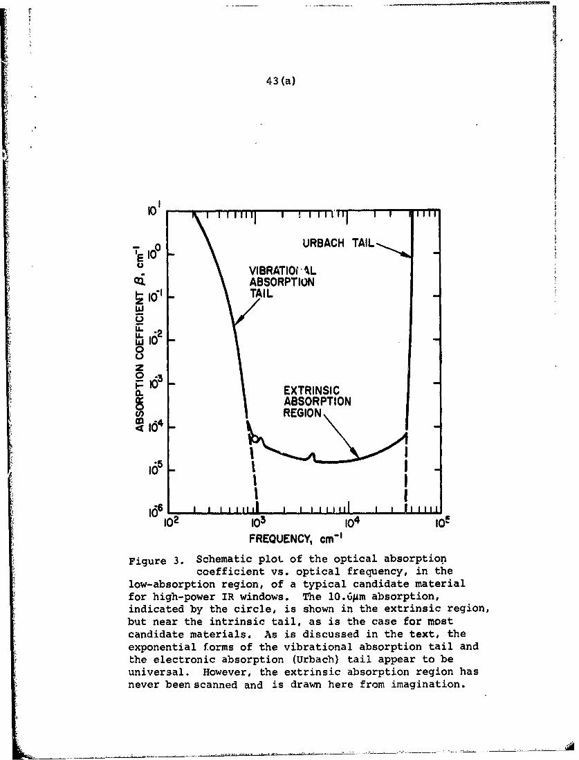
43 (a)
-QURBACH TAIL
U VIBRATIOCAL
| ABSORPTIONiTAIL
W
00z
10610 i EXTRINSICABSORPTIONREGION
4100
102 103 lO ogFREQUENCY, cm-1
Figure 3. Schematic plot of the optical absorptioncoefficient vs. optical frequency, in the
low-absorption region, of a typical candidate materialfor high-power IR windows. The 10.6pm absorption,indicated by the circle, is shown in the extrinsic region,but near the intrinsic tail, as is the case for mostcandidate materials. As is discussed in the text, theexponential forms of the vibrational absorption tail andthe electronic absorption (Urbach) tail appear to beuniversal. However, the extrinsic absorption region hasnever been scanned and is drawn here from imagination.
-44-
1. Lattice Vibration Absorption
There have been a number of recent studies of
how the infrared absorption drops off as the frequency
becomes much greater than the fundamental lattice absorp-
tion frequencies, and the prominent overtone or combination-
absorption frequencies. 6 -8)These studies have been mainly
on the alkali halides.and MF2 crystals. In the more
highly purified samples, it appears that the absorptioncoefficient, O(w), universally exhibits an exponential
fall-off over the lowest two-to-four decades of that are
measurable. That is, for w >> WTO
-W/WOo (IV-5)
where w is never far from the reststrahl frequency wTO0 (9)
and varies little with temperature at room temperature.
(For example, w w WTO for KBr.)
In some crystals (e.g., AL203, SrF2, BaF2, LiF, and
CaF 2) the observed absorption at 10.6Mm is clearly part of
this tail and, therefore, probablv intrinsic. However, in
these cases the absorption at 10.6Mm is so high that the
crystals are not good window material candidates. It is
probable, though not certain, that the observed low
absorption at 10.6Am and 2-5Mm in many of the more
interesting candidate materials (KBr, TI(Br,I), KCA, ZnSe,
CdTe, GaAs, and Ge crystals and chalcogenide glasses) lies

-45-
above this intrinsic absorption tail roughly as illustrated
in Figure 3. This is certainly the case in the 2-5Mm
region.
Whether this exponential absorption tail is
characteristic of all other classes of materials, including
glasses and nonpolar crystals, is not yet known.
2. Free-Carrier Absorption
The theory of B-2 above and the approximate Equa-
tion (IV-2) may also be applied to intrinsic free-carrier
absorption. The only interesting material for which this
absorption may be an important limiting factor at 10.6Mm
is "ultrapure" germanium, inch-size crystals which have
recently become availableo(10)This case will be discussed
in detail in Chapter VII.
It has been suggested that even though free-
carrier absorption is negligible, free carriers may
contribute significantly to absorption below the band gap
by interband transitions in semiconductors. (11)The cross
sections for such processes deserve further investigation.
High intensities at infrared and/or visible and ultraviolet
frequencies may increase the free-carrier concentration by
photo-excitation. The resulting intensity-dependent
(nonlinear) absorption has not yet been analyzed.

-46-
3. Bound-Elactron Excitation
Only those materials that have a band gap (i.e.,
minimum nominal energy to excite bound electrons to a
conduction band) much larger than the infrared frequencies
of interest need to be considered. It is, therefore, only
the low-frequency tail of the fundamental gap absorption
that might be of importance in the low-absorption window
under consideration. This tail, 0t(w), to the fundamental
electronic absorption has been observed to be of the form
e ChW/k BT (IV-6)t
in a wide variety of ionic, covalent, and amorphous
materials. (Here, C is a constant of the order unity, kBis Boltzmann's constant, and T the absolute temperature.)
This dependence was first noticed by Urbacb in alkali
halides and has been found to be so widespread that it is
called Urbach's rule. 12)The most recent and promising of
many attempts to construct a theoretical basis for this
general behavior is that of Dow and Redfield. (13)
In any event, it would seem that we may estimatewith some confidence the contribution 0t to the intrinsic
absorption from electronic transitions by extrapolating
measurements made just below the band gap. 14)The Urbach
tail for a typical material is indicated in the 0 vs w
plot of Figure 3. The Urbach tail is so steep that it
could produce significant absorption only for those materials
-47-
whose band gap is not much above the infrared frequency
one wishes to transmit, that is, only for smalJ.-band-gap
semiconductors.
D. Surface and Coating Absorption
Surface and coating absorption can affect high.
power-window performance in several ways. The surface
heating can cause thermal distortions of the optical phasefront. If fragile surfaces, such as of the alkali halides,
are subjected to high-power beams, the surface cracks and
imperfections may propagate or enlarge, or become hygro-
scopic. When anti-reflection or passivating coatings areused, surface absorption may tend to dislodge or even
evaporate the coatings. The theory of surface and coating
absorption may be thought of in terms of the same six
categories that we have used in discussing bulk absorption:
by vibrational, bound-electronic, or absorption free-
electronic excitations of either extrinsic or intrinsic
types. Problems of surface and thin-film coatings are
commented on separately below.
1. Surface Absorption
There is some evidence that surface absorptionby oxygen bonds has been observed near 2.7gm in various(6)crystals. In this case, as in B-1, an absorption crossthsection, ai, is assigned to the i impurity bond type andthe fraction of thc beam, FS, absorbed at the surface is
written as

-48-
FS (w) =E .i M.i a.(W) , (IV-7)
where M. is the number per unit surface area of this type1
of imperfection. For example, to estimate the surface
absorption at 10 .6pm due to a monolayer of oxygen, suppose
that the cross section,a i is on the order of the bulk
absorption cross section (- 10- 18 cm 2), and the number per
unit area,Mi,is the two-thirds power of the atomic density
of the crystal (- 10 1). In this case Fs is estimated to be-3
of order 10 . Although this is a significant fractional
absorption in high-power applications, it is very difficult
to measure with existing techniques. Perhaps if the ai
could be determined for the important impurities, the more
easily measured surface density,Mi.,would give a useful
estimate for the surface absorption,Fs,of a given simple.
Both linear and nonlinear absorption by surface
free carriers and surface bound-electron states may well
be important but have received little attention to date.
2. Thin-Film Coatings
In addition to introducing extra surfaces and
their associated absorptions, thin-film coatings have a
"bulk" absorption that may often be allowed to be signifi-
cant in order to obtain other characteristics required of
a useful coating. Unfortunately, it has become evident
that the absorption coefficient,O ,in films is generally
much larger than the 0 for the same nominal material in
bulk. (5)

~i
-49-
The real part of the refractive index measured in a film
is also different from that measured in bulk. These dis-
crepancies have been observed to be a function of film
preparation and the mechanisms responsible are not yet
understood. (15)Nonlinear absorption processes are more
likely to be important in films than in bulk but estimates
of these have not been made.
E. Conclusions and Recommendations
It is probable that the low, but deleterious,
infrared absorption that has been measured in the best
candidate materials for high-power-laser windcws is
extrinsic in origin. Therefore, the possibility exists
that more careful preparation and purification of these
materials will lower their absorption. Unfortunately, the
materials with the best thermal and mechanical properties
tend to need the most improvement in absorption. From our
review in this chapter of the gaps in theoretical knowledge
of mechanisms of absorption, we conclude that a better
theoretical grasp of the following facets of the absorption
problem would aid the choice and fabrication of a satis-
factory high-power infrared-laser window. The list is
arranged roughly as we see the relative priorities of the
theoretical problems to window fabrication.
1. The limit to the improvement in absorption is
set in most materials by the level of intrinsic vibra-
tional absorption at frequencies well above the intrinsic
absorption resonances. This absorption tail has been

-50-
traced experimentally so far mostly in polar crystals,
where it has been f.)und to be exponential over the lowest
decades of absorption measured. This behavior should be
given a theoretical basis from which to predict a) whether
the exponential trend persists to lower absorptions, b) how
the absorption tail behaves with changing temperature and
composition, and c) if this tail is to be expected in other
classes of materials, especially glasses and nonpolar
crystals.
2. It is clear how various species of ionic impuri-
ties can vibrate to cause "local mode" or bond absorption
resonances above the reststrahl bands. However, these
impurities may cause a much less obvious raising of the
background absorption by virtue of the anharmonicity,
disruption of periodicity, and general change in phonon
couplings which they cause. A simple model of this effect
ought to be devised by which an estimate of the changed
background vibrational absorption could be made.
3. At the high levels of both the infrared-beam
intensity and the ambient visible and ultraviolet inten-
sities that high-power infrared-laser windows may have to
withstand, photoconductive free carriers may introduce
troublesome added (nonlinear) absorption. From existing
data on the wavelength dependence of photoconductivity,
theoretical estimates should be made of this effect in
candidate materials. These effects of photo-excitation
seem to deserve special attention at surfaces and in
surface coatings.

-51-
4. Free carriers, whether extrinsic, intrinsic, or
photo-excited, may absorb by interband transitions. Such
absorption might well peak at frequencies above the laser
frequency and exceed normal (intraband) free-carrier
absorption at wavelengths of interest. Some straightforward
band theory ought to provide a prediction as to when such
an effect might be important.
5. The aboorption by electrons localized on impuri-
ties usually peaks at much shorter than infrared wave-
lengths. SucL absor:ption commonly has been observed to be
so strong at its peak that it may well contribute a small
but significant absorption at the longer laser wavelengths
of interest here. The theory of the shape of these elec-
tronic absorption tails on their low-frequency side should
be developed in analogy with the existing theory of the
Urbach tail.
6. Although many of the discrepancies observed
between values of absorption and refractive index in bulk
and in thin film can be attributed to "dirt" effects,
there may be some intrinsic change occasioned by the forced
lattice distortions and proximity of surface states in the
films. It would be helpful to the development of window
coatings if some rules-of-thumb could be developed to
predict the nature of these absorption and index discrep-
ancies.
To this list many other special topics might be
added. Studying subjects such as the formation of color
centers. radiation damage, and light scattering from
//
-52-
impurities might well expose some important contribution
to the eventual amount of heat that will be deposited
from a laser in the window material. The Committee can
only hope to have uncovered some of the more obvious
problems and assessed them cursorily in a study so brief
as this.
Considering the nature and degree of complexity
of the problems identified above, the Committee feels that
about $100,000 per year spent over the next two years is
required to yield a body of answers that would provide
satisfactory guides to window design.
-53-
REFERENCES
1. R. C. Newman, Advances in Physics, 18, 545 (1969).
2. W. G. Spitzer, Advances in Solid State Physics,
(Festkorperprobleme) XI, 1 (1971).
3. S. Nielsen and J. A. Savaqe, Infrared Physics, 5, 195
(1965): "Chalcocrenide Glasses Transmittin in the
Infrared between 1 and 20jim.
4. A. Vasko, D. Lezal, and I. Srb, J. Non-Crystalline
Solids, 4, 311 (1970): "Oxygen Impurities and Defects."
5. Proceedings of the Conference on High Power Infrared
Laser Window Materials, (October 1971). Ed. by C. S.
Sahagian and C. A. Pitha (Air Force Cambridge Research
Laboratories, Special Report No. 127, December 1971).
6. F. A. Horrigan and T. F. Deutsch, Final Technical
Report, Contract No. DAAH01-70-C-1251, (September 1971),
"Research in Optical Materials and Structures for
High-Power Lasers."
7. L. Genzel, Fest Korper Probleme, 6, 32 (1967),
"Optische Absorption von Fest K6rpern durch
Gitterschwingungen."
8. G. Joos, reproduced in Introduction to Solid State
Physics (4th edition) by C. A. Kittel, (John Wiley,
New York, New York, 1970),, P. 155, from FIAT Rev.
Ger. Sci. (1939-1946) Part II: The Physics of Solids,
"Optische Eigenschaften der Festen K6rper."
-54-
9. F. A. Horrigan and R. I. Rudko, Final Technical Report,
Contract DAAHO1-69-C-0038, Raytheon Research Division,
(September 1969), "Materials for High Power CO2 Lasers."
10. R. N. Hall, General Electric Research and Development
Center, Schenectady, New York. (Private communication)
11. H. B. Briggs and R. C. Fletcher, Phys. Rev. 91, 1342
(1953); A. H. Kahn, Phys. Rev. 97, 1647 (1955);
J. D. Wiley and M. D. DiDomenico, Jr., Phys. Rev. B3,
375 (1971).
12. F. Urbach, Phys. Rev. 92, 1324 (1953). For A review
of Urbach's rule, see J. J. Hopfield, Comments on
Solid State Physics, I, 16 (1968).
13. J. D. Dow and D. Redfield, Phys. Rev. Letters, 26,
762 (1971), "Theory of Exponential Absorption Edges
in Ionic and Covalent Solids."
14. W. Martienssen, J. Phys. Chem. Solids, 2, 257 (1957).
15. P. A. Young, Thin Solid Films, 6, 423 (1970); P. A.
Young and W. G. Thege, J. Phys. Soc., London, D4,
64 (1971).
-55-
V. EXPERIMENTAL ASPECTS IN THE CHARACTERIZATIONOF HIGH-POWER INFRARED-WINDOW MATERIALS
The significance of a large number of mechanical
and optical properties for high-power-infrared windows has(1)(2been discussed extensively by Sparks and others.(2)
The properties are listed below for the sake of completeness
and may give the appearance of a formidable list, but it
should be emphasized at the outset that only a few of the
many characteristics will require special attention and
that no major new survey of possible material candidates
is required. For a complete characterization of a high-
pe)wer infrared-window material, the following data must be
obtained:
1. Optical absorption spectrum, including the
determination of the band gap and optical
phonon energies.
2. Index of refraction n and its temperature
coefficient dn/dT, both in the wavelength region
around 10.6sm and in the 2-6gm region.
3. Residual optical absorption coefficient 0 in
transparent regions.
4. Light scattering characteristics and large-scale
optical homogeneity.
5. Density, specific heat, and melting point.
6. Thermal conductivity and thermal expansion.
7. Hardness, and resistance to abrasion and moisture.

-56-
8. Yield and fracture strengths.
9. Elastic moduli and photo-elastic constants.
10. Electrical dc conductivity.
11. Resistance to radiation-induced optical damaqe.
Many of these properties have been tabulated for
important classes of materials, and these tabu!at ions may
serve as a guideline in selecting candidates for infrared
window materials. These general properties will be dis-
cussed separately for different classes of materials in
the subsequent sections on ionic crystals, covalent semi-
conductors, glasses. and polycrystalline materials.
Whenever a new material or a new processing or
fabrication technique is developed, all of the above- 0
mentioned characteristics should be determined. Most of
these quantities may be measured by standard experimental
techniques. Several quantities are insensitive to details
of the fabrication procedure and to the nature of additives
and impurities, e.g., the band gap, optical phonon energies,
specific heat, Poisson's ratio, etc.
The mechanical properties of hardness and tensile
strength, and to a lesser degree thermal conductivity, are,
of course. very sensitive to heat treatment, recrystalli-
zation procedures. alloying impurity content,and fabrica-
tion techniques including, for example, hot or cold pressing
and sintering. Eowever, once the material has been prepared,
measurement of these properties poses no special problems.

9
-57-
The numerical values of these properties lie in a rather
conventional range.
By contrast, the measurement of low-optical
absorption-coefficients presents a more specialized problem.
It is obviously desirable, as follows from the theoretical
discussion in the preceding section, to minimize the
optical absorption. Acceptable window materials usually-3 -1
have a bulk-absorption coefficient of 0 < 10 cm , and-4 -l
values of 0 near 10 cm are often preferred. Such low
values cannot be measured accurately by total attenuation
of the beam in transmission. In this case one measures
both losses due to scattering and absorption, and the
former may well be dominant. Furthermore, the measurement
of the absorption coefficient would be imprecise because
the ratio of the incident and transmitted-light intensity
is very close to unity.
The most reliable way to measure the (small)
absorption coefficient is to measure the heating of the
sample, when exposed to a well-defined laser beam of known
power. The sample is mounted to provide sufficient thermal
isolation and thermocouples are applied to sense the tem-
perature at several points on its surface. The cooling
rate may be varied by controlling the ambient-gas pressure.
One measures the rate of heating and/or the final steady-
state temperature in the presence of the laser beam, as
well as the cooling rate when the laser beam is shut off.
It is possible with this method to measure absorption
coefficients as low as 10 -5 cm (4.3 db/km) with an
-58-
accuracy of ten percent. Such data were reported by
Pinnow (3) on fused silica with a Nd-Yag laser beam. Since
cw CO2 and CO laser beams, etc., in a well-defined geometry
with power levels exceeding 10 watts are readily available,
the same technique is clearly adequate to establish the
absorption of infrared-window materials at the respective
wavelengths. The rise in temperature could also be deter-
mined by cptical interferometry. Another method of deter-
mining low-bulk absorptivity consists of measuring the
thermal emissivity of the material over a range of tempera-
ture and wavelengths.
Scattering losses may be determined by directly
observing the scattered light. Even in a perfectly homo-
geneous material there will be Rayleigh and Brillouin
scattering due to entropy and pressure fluctuations.
These intrinsic scattering losses have an order of magnitude
of about 10-6 cm in glasses. Since they can be calculated
theoretically with good precision, the Brillouin components
may be used to calibrate (3)the scattering losses due to
inhomogeneities, etc. This method has been applied to
optical glasses at 1.06Mm and in the visible range.
The intrinsic scattering losses would be many orders of
magnitude smaller at 10,6pm and would be very difficult to
observe. Fortunately, the scattering in the infrared
window is only of interest insofar as it substantially
degrades the transmitted beam. Even if as much as one
percent of the infrared light were scattered out of the
incident mode, this would not impair the window operation-
ally. It is necessary, however, to determine the spatial

-59-
characteristics and mode structure of the transmitted beam.
One may expect significant small-angle scattering, especially
in sintered, microcrystalline materials. This scattering
could be determined experimentally by moving a pinhole across
the beam profile a suitable distance away from the windoA,
sample.
The presence of a large amount of scattered light
may influence the absorption measurements in a significant
way, as was pointed out by Winsor. (4 ) A substantial fraction
of the scattered light may be repeatedly reflected totally,
especially in window materials with a high index of refrac-
tion. In this manner the light will travel a very long
path in the crystal and eventually be absorbed, leading to
an apparent enhancement of the absorption coefficient.
Although an erroneous value for 0 would be obtained, it
must be pointed out that the calorimetric measurement in
an actual window geometry measures precisely what is needed
from an operational point of view. It measures the temper-
ature rise due to all causes of absorption, including
trapped scattered radiation. Apporently very little work
has been d,:.ne on the scattering of infrared radiation
in window materials. Accurate measurements of the scatter-
ing in well-defined geometries, especially in the near
forward directions, are needed.
There are obviously some experimental advantages,if the infrared-window materials are also transparent in
the visible or near ultraviolet. Such is the case, for
example, in the alkali halides. In this situation the

-60-
scattering characteristics may readily be observed in the
visible range, and the infrared scattering properties
deduced by appropriate scaling with wavelength. Since the
low level residual absorption with 0 - 10- 3 cm-1 can
sometimes be attributed to impurities, which also have
characteristic ultraviolet absorption spectra, the concen-
tration of such impurities may more conveniently be
monitored, with higher precision, at the shorter wavelengths.
Over-all optical quality control of the window and its
distortion due to thermal effects may in this case also be
monitored by utilizing interferometric techniques in the
visible range. This would again significantly simplify
testing procedures.
Since high-power-infrared windows probably
will need anti-reflection coatings in all. cases, and the
alkali halides, and perhaps some other materials, will need
protective coatings to withstand attack by moisture from
the atmosphere, (5)the optical absorption and scattering in
surface coatings must also be determined. Unfortunately,
low-index anti-reflection materials all have a high coef-
ficient of absorption at 10.6Am. The net absorption in a
layer a few micrometers thick may equal the bulk absorption
in a window several centimeters thick.
Molecular layers, especially those containing
oxygen adsorbed on the surface, may absorb as much as one
hundredth or even one tenth of one percent of the incident
intensity. In addition, surfaces also may have an intrinsic
absorption due to electronic surface states and surface

-61-
vibrational modes. The heat contact between coatings and
the bulk window may be substantially lower than that calcu-
lated from bulk conductivities. Very few experimental
data are available on the absorption of high-power-infrared
radiation at surfaces. This important question needs
immediate attention. If the heat is conducted into the
bulk, calorimetric measurements will include the surface
and coating absorption.
The scattering from coatings and surface layers
is similarly included in the pinhole probing and inter-
ferometric techniques described above. If it is desired
to measure the properties of coatings in situ, but separately
from the bulk, this can be accomplished by a totally
reflected beam technique. (2)The laser beam is shone into
the bulk wiindow material from the side at such an angle
that repeated total reflections at the surface layer occur.
Absorption in the layer and scattering by the layer can
thus be determined.
Conclusion
While most material characteristics of infrared
windows may be determined by standard measurement techniques
with commercially available instrumentation, the measurement
of low absorptivities, smali- and large-angle scattering,
and optical distortion requires especially constructed
calorimetric and optical-bench arrangements.

-62-
Recommendations
1. It is recommended that experimental facilities
to measure all pertinent optical, thermal, and
mechanical properties be closely integrated with
each development project for infrared-window
materials. Arrangements for exchange of data
and samples, and access to testing facilities
of other groups should be improved.
2. It is recommended that measurement of the
absorptivity of surface layers and coatings and
of the temperature rise and resistance to mechan-
ical deformation of such layers, when exposed
to high-power infrared-flux densities receive a
high priority. Some attention also should be
given to the changes in optical and mechanical
properties of coating and window materials
induced by exposure to ultraviolet and nuclear
radiation and to thermal cycling.
i,
-63-
REFERENCES
1. M. Sparks, J. Appl. Phys., 42, 5029 (1971). Rand
Report R-863 PR, Santa Monica, California, (August
1971), Physical Principles, Materials Guidelines,
and Materials List for High-Power 10.6am Windows.
2. F. A. Horrigan and T. Deutsch, Research in Optical
Materials and Structures for High-Power Lasers,
Final Technical Report under Contract DAAHO1-70-C-1251,
Raytheon Research Division, Waltham, Massachusetts,
S-1335, (September 1971).
3. T. C. Rich and D. A. Pinnow, Applied Physics Letters,
20,264, (1972). (Presentation by D. A. Pinnow to the
Committee, November 1971).
4. H. V. Winsor, Air Force Weapons Laborabory, Kirtland
Air Force Base, New Mexico. (Presentation to the
Committee,September 1971. To be published.)
5. P. A. Young, Thin Solid Films, 6, 423 (1970).
P. A. Young and W. G. Thege, J. Phys. Soc., London,
England, D4, 64 (1971).

-"- -65-
VI. SINGLE CRYSTAL ALKALI-HALIDEINFRARED-WINDOW MATERIALS
A. Introduction
In this chapter ionic crystals that are trans-
parent for radiation at 10.6m and 2-6m wavelength are
evaluated with respect to their potential as high-power
infrared-window materials. The most promising substances
in this class appear to be halides of certain monovalent
and divalent metals.
The main advantages of materials in this class
are their low-intrinsic absorption and their availability
in sufficiently pure form and large sizes. Low-bulk
absorptivities acceptable for window applications have
been demonstrated. The optical figure of merit is high.
The main disadvantages of the pure ionic single-
crystal materials lie in their mechanical properties;
however means exist for improving these without sacrificing
the optical quality. In addition, some material candidates
at 10.6pm are hygroscopic and need a protective coating
against atmospheric attack. The weak and strong points of
ionic crystals are summarized in Table I and compared with
the corresponding properties of semiconductors and glasses.
B. Optical Properties and Figure of Merit
The conditions for distortion-free transmission
have been given in Chapter III and for this discussion
Equations (111-20) and (111-21) shall be used. At
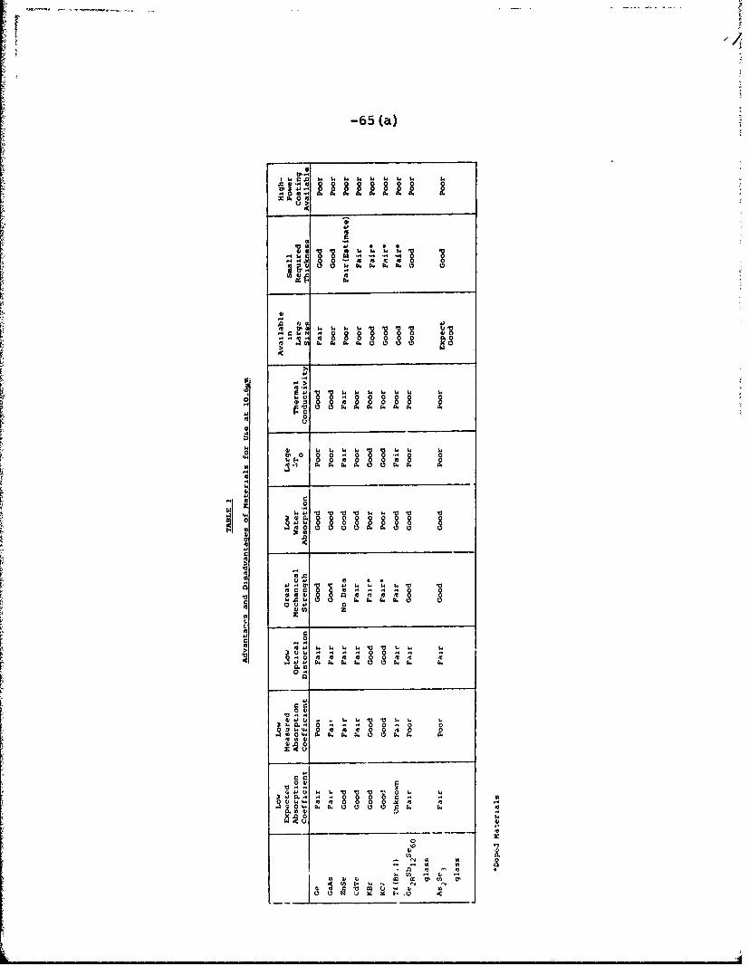
-65 (a)
E a
~a, 04
A 4 ,
400
'04 4. u 1 w 1 w
014 V 4.44 0
8 8
00 01. .
o , 0
00
44 ~ ~ 84E 841k
2.. o
4.m
410 xx R x 8

-66 (a)7
A12 03
10 SiI I
QI/IIM
0.6p10m6IM
0-61 1DG I LI~1 ~ ~ I 2I 8 03 05 I
FigureI 4.Apoit vsw eln hfovaious Iaeil

1//
-67-
(10)appears to have been made to lower the bulk absorptivity.
Empirically, it is found that for the alkali
halides the reststrahl edge is displaced toward longer
wavelengths as the bond length from cation to anion
increases. To the left of KCI in Figure 4, 0 tends to be
toc large to make the material of interest at 10.6Mm. To
the right of KBr, poor thermal conductivity, low volume
heat capacity, and larger values of 6nAT tend to cancel
any advantage due to a lower 0. Furthermore, the difficulty
in increasing yield strength or the greater hygroscopic
character also adds complications for these compounds.
However, the comparable TA compounds are not hygroscopic
and consequently do not require protection from moisture.
Their tendency to develop a poorly defined (or mosaic)
crystal structure is a source of considerable scatter at
0.684m(11 )but is probably not serious at 10.6Mm. Physical
properties and performance characteristics for various
halides are listed in Table 2. CdTe, Si, and As 2Se3 are
added for purposes of comparison.
KBr appears to be one of the better choices for
a low-loss window at 10.61m. As for other alkali halides
this material requires protection from moisture, Young
has shown that NaCk, tightly sealed with a vitreous coat
of As 2S3 , - 2Mm to X/2 thick, can be remarkably stable. (7)
This is a convenient match for small windows as the thermal-
expansion coefficient for As 2S 3 (25 x 10-6/ "C) is just a230-6/little less than that for NaCA(31 x 10 / C). The difference
is in the right direction to allow for the greater heating
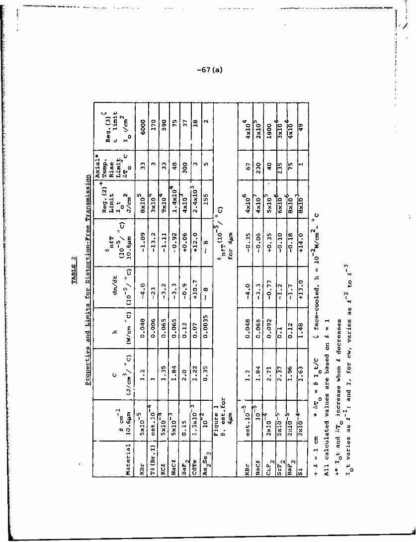
1.>
-67 (a)
0 0 0 t- D N N n N0 N O0 N m H 0 0 00 0 0
N 0 H n H 0 -I H v
0 0 " H
S M" 64 0 m rn 1 0 en e m -
0.O +
00
tn -, 0,M M Ln
... ,- L 'I LA
2 0.~ 00 XO0 X LA 0 00 00V)~4 H~H~ H H H H H Hq
w -H 0 x x x LA'0x
r_ _ - - - - - - - aO :U If 0,, P
,0 -, -$4 N HN 0 0 0 0 L o 0
r14 EN 0 *HO0 0 H . f 0 H . U~LA ~ ~ * * N II 'I 0! * *'r.'0 HHH E1 000 0 H
0 0 + + 4 1 + I I + NS .,I PH -4 0 0
W0
0 ,- '
) U w -O I N 0H Nt OH H H 0 N
0.-I I I I + H I IH 0 -U- )OI 0
.9-4 ,- ,-01
4.) LA
m m0 OD A LA N U -H A w) US0 w0 w N NO 0 v0a% N(D M 004
E H 0 000 H0Ix u 9 * ' 9,. . * . . , . , 0 I, e
0 0000000 00000oH o 0
0 0
41 ) 0 %t U
0LA Nt N LA H N- 0 m~ 430 m 0N N m w 0 N m ~ O 0 A~ 44
0
14 0 U) 0 to0 E- Z W
F-4 H 'I4 LA '1 I H uE n C 1 044-4 0 o0 uLn 1 >' -4:1 1 H HI "1 1 $40g 1
kLf 4 - - '~ H4 tL 43) H- H H H- 0 E4 Umn X U) X . ., * . V) x x x 4310 e
H A 0 Ln LAO 'i C4 dl 0) N4 LAN N 0u
$4~ 11 u 0>
04 N Cf4 N N' N H4 - -Z U r E4 N W- U r34 N HU 140 4 u m~ to w 00 (1 U) 14i 1 H1 -4i 0
x E- x___m u cI ZjC~ 6JnI Jul + 4 + H

-68-
of the film due to higher absorption; vitreous films arerequired for these coatings as moisture will penetrate
(7)polycrystalline films by migrating along grain boundaries. (
Selenide glasses are much less lossy than sulfide glasses
at 10.6Mm. This suggests that As Se would be a better2 3
coating for KBr windows at this wavelength. HQwever, as
the thermal expansion coefficient of As 2Se 3 is - 21 x 10 C-6oas compared to 43 x 10 / C for KBr, expansion differences
could be serious for large windows. This problem may be
alleviated by using chalcogenide glasses with low elastic
moduli. These include glasses with high Se or Br content.
These vitreous coatings also serve as a protection against
color center formation by ultraviolet radiation and may
serve as the high index component of an anti-reflection
coating (BaF2 is commonly used as the lower index component).
The thallium halides, Ti(Br.I), have the advantage
that they do not need protective coatings. They should
also be capable of sufficient purification so that B
-4values lower than 10 may be expected. They have, however,
a large 6 nT value because the temperature coefficient of
the index of refraction is high. Consequently, this
material would need very good thermal control as the
maximum permitted temperature differential AT across the
window, according to Equations (111-7) and (III-ll), is
small T0 < e X/ (84 5 nAT I ). This would appear to make
these materials less desirable than some alkali halides,
notably KBr, but their window potential should be more
carefully evaluated. They could be most useful in geome-
tries with very efficient and well-controlled cooling.

Although the 0 value for BaF is large at 10.6Mm,2the material may be of some interest at this wavelength
due to a very small value of 6' by near cancellation ofnAT
(Bn/6T) and thermal expansion. Such windows can tolerate
a high-temperature gradient without excessive distortion.
For thin BaF windows, an axis to rim temperature difference2
of ATo > 1000 C is permissible. Low values of 8' seem to0 n1Tbe characteristic of low-n materials auch as the fluorides.
Consequently, they may be used to great advantage in the
2-5)m region where their absorption is low.
Since the various terms that compose 6 andn4 T
6' are functions of the optical index n, it is instructivenA Tto show an empirical trend. In Figure 5, 6 values for
10.64m and 6' values for 4Am are plotted versus n fornAT
the MF fluorides. The comparable values for alkali halides2are represented in Figure 6. It is of particular interest
that, for the MF2 compounds, both i and 6'T approach a
zero value near n - 1.43. It should be kept in mind that
the cancellation cannot be exact over a wide range of
temperature and that anisotropic stress effects will also
prevent a true zero. Nevertheless, BaF and SrF should2 2
have a good optical figure of merit for a wide range of
wavelengths. They should be very desirable candidates in
the 2-6Mm region. The absorption is, however, excessive-l
at 10.6Am under ordinary conditions ( 0.15 cm for(3)BaF )3 This absorption in the tail of the infrared-
phonon bands may be reduced and the yield stress
increased (12) by refrigeration,and the use of BaF 2 at 10.6gm
in the form of very thin, segmented, refrigerated windows
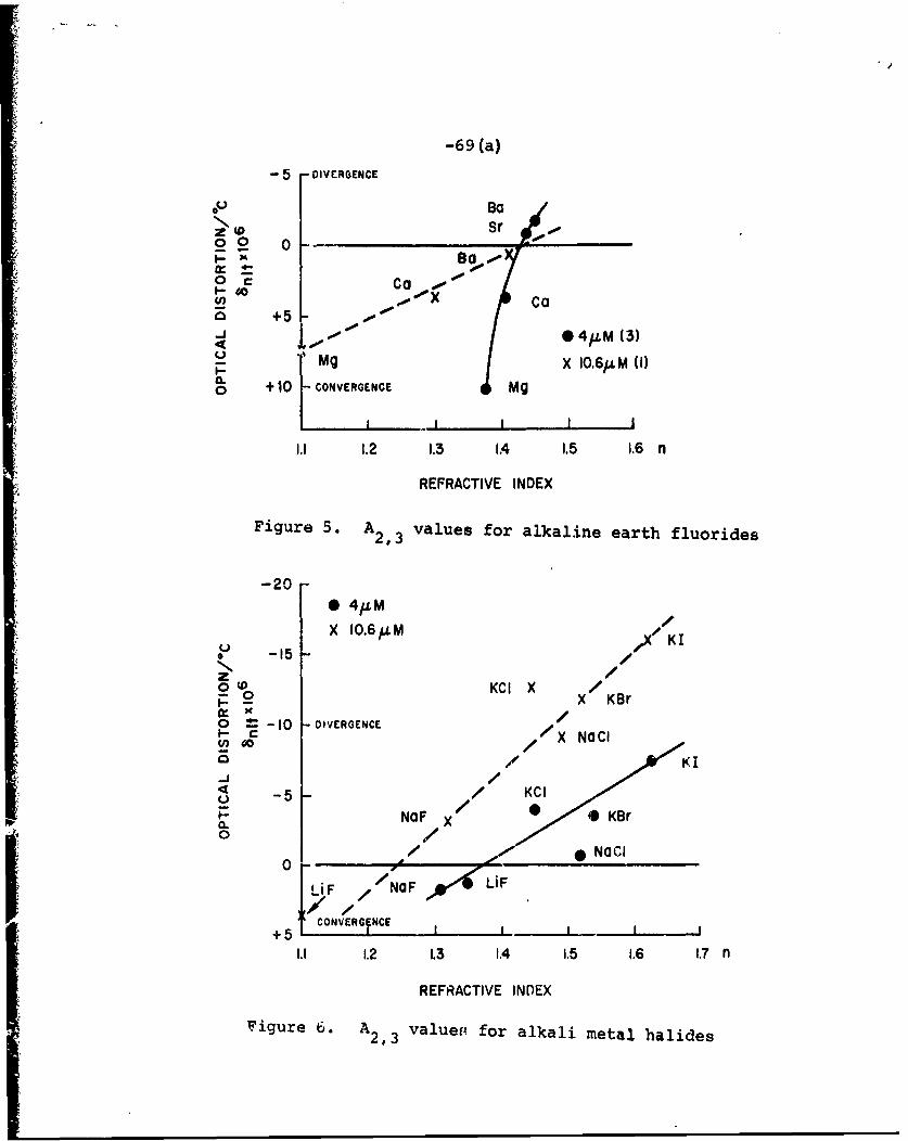
-69 (a)
- 5 -DIVERGENCE
-BO 0Sr 0
0 0 0
0 ca00 0so
.0 iX C a
7' +5 01<j ,0. 4/JLM (35)
Mg X 10.6/M (1)(-0 +10 - CONVERGENCE Mg
1.1 1.2 1.3 1.4 1.5 1.6 n
REFRACTIVE INDEX
Figure 5. A2, 3 values for alkaline earth fluorides
-200 4 LM
X 10.6bLM /I
0 -15 /zo KCI Xp X KBr
0 1 -0 DIVERGENCEX NOCI
4-) -5 KCI
p ~NOF X Kr
/NCI
00
OF NOF LiF
CONVERO NCE+5 IIj
1.1 1.2 1.3 1.4 1.5 1.6 1.7 n
REFRACTIVE INDEX
'igure 6. A2, 3 valuer; for alkali metal halides!2,3
-70-
cannot be entirely excluded.
Anti-reflection coatings for BaF2 should have an
index of n - 1.2 at 10.6pm. Such low values are difficult
to obtain without taking advantage of dispersion and
suffering the accompanying absorption effects. NaF may be
used for this purpose.
c. Mechanical Properties of Ionic-Window Materials
The advantage of the excellent properties of
some selected ionic crystals is unfortunately offset by
less desirable mechanical properties of these crystals in
their pure form. There are, however, ways to improve their
mechanical strength. One method consists of using a mix-
ture of cations or anions in single crystals. Another
method which will be discussed in detail in Chapter IX
consists of press forging single crystals so that some
recrystallization Lakes place. It will be important to
assess whether the desirable optical properties can be
maintained when these m,thods are used.
The yield stress a or the elastic limit must be
as large as possible in a direction normal to the window.
For the halides with the NaCI-type structure, the slip
direction is <110> and the slip plane is 11101 • Hence,
if one aligns the window so that the axis is <111>,
either the slip direction or the slip plane normal is
perpendxcular to the pressure direction across the window.
Therefore, the resolved shear stress is zero and slip or
rupture is suppressed. For compounds with CsCl and
-71-
CaF 2-type structures (e.g., TA(Br,I) and BaF 2), the com-
parable pressure resistant axial alignment is <100>. In
practical cases the yield stress may be increased by
proper orientation by a factor f w3. The ratio of thick-x
ness I to window diameter d is inversely proportional to
the a value in the weakest direction and to f . If the
maximum pressure differential AP is expressed in pounds
per square inch and the safety factor,f SF,is introduced,
a uniformly loaded circular window needs the following
thickness to diameter ratio:
d = 0.56a f/yx
For hardened KBr, with fSF = 10, fx = 3, and AP = 7.5 psi,
one obtains 1/d = 0.04.
There will be some elastic distortion of the
window due to AP. To a first approximation, the bending
of a uniformly loaded window will not cause optical dis-
tortion, but a more precase analysis shows that effects
exist proportional to E2/ 5, where E is the Young's modulus
in the normal direction.
There will be a self-imposed pressure differen-
tial due to the weight of the material alone. Comparison
of the optical distortion induced by elastic deformations
with those caused by thermal-expansion coefficient a at
the maximum permissible temperature differential AT, shows
that the ratio LP/EaAT is small compared to unity, except
for extremely thick T1 halide windows.
In • , n • , n • , n • •

-72-
The yield stress,(a ),for the pure alkali halides
may be as low as 100 psi; however, by mixing anions or
incorporating divalent cations, a,<io0> can be raised to
> 5000 psi. The relation between Knoop's hardness HK
Young's modulus E<,,,> and E<100> and ay<100> for variousmaterials is discussed in connection with Figures 7-9.
Figure 7 depicts relations between E<III> and
E , R for halides of monovalent cations.<10 <0>(3)Comparable values for MF2 compounds are given in Table 2.
The values for Young's modulus were calculated
from sound velocity measurements. The values of H. for
the pure halides are from References 6 and 14.
The points plotted in Figure 7 are for E<11l>while the arrows originating from these points extend to
the values for E<100> . In general, HK< 1 00> for the simple
K, Na, and TA halides of CA, Br, and I equals
N<100> ' E<111> ' (VI-1)
11 2when E is in units of 10 dyne/cm2 . Deviations for CsBr,
TA(BrI) and TA(Br,CA) are attributed to the presence of a
mosaic structure and/or anion mixing.-
Although Young's modulus is little affected by
cation impurities, anion mixing, or mosaic structure, HK
and a may be increased by factors of two to three and two
orders of magnitude respectively. Further, for the NaCA
structure

-72 (a) -
50
TI(Br, I)
40 C
TI( Br, CI)
30
0
S20 -Cs Br
Ti CI-,
10 - Ag C I*200
e zz
I 2 3 4 5
E (I0"dyne/cm2 )
Figure 7. Knoop's hardness vs Young's modulus.
Deviations from linearity for the <111> data
are attributed to mosaic structure. (17)
I,

-72 (b) -
TABLE #3
E<111> E<100>Flexural
11 2Elsi(10 03mes/cm )H K<100> Lasiti
CaF' 9.05 14.2 120 4500 psi
SrF 2 8.16 10.0 130 6000
2b 6.97 5.6 200 1300
BaF2 6.57 6.5 65 3000
-73-
2a
Y<1ll> y<100>
and for the CaF 2 structure
a~>a
vY<i00> Y<l1l>
The yield strengths discussed in the preceding paragraph
refer to directions of easy yield as determined by pre-
ferred directions of cleavage or by a flexural method of
testing. For properly oriented windows the applicable a
value will be increased by the factor f , which may be as
large as 3 to 5.
The relation between HK<.00> and ay<100> for
several series of alkali halides that have been doped withdivalent cations (M 2+ ) are depicted in Figure 8. The com-
position of the melt from which the crystal ,.As grown or
the formula fraction of M2+ present is indicated. Values
for samples annealed near 7000C for one-half hour in air2+
are indicated by a bar above the M2 symbol (e.g., Sr).
The data fall along parallel lines, one for each alkali-
halide host. The slope is
Y/AH K = 300, (VI-2)
when j is in units of psi, and the extrapolated intercept
on the H ( axis is near the value for the pure halide.
Therefore, one may write for the alkali halides
HK = HO + Hx , (VI-3)
-73 (a)-
9000LIMITED
BY TWINM AS GROWN FORMATION I8000 - i ANNEALED AT ~700*C.
TI (Br, I): Ba
KBr KCI NOCI, 7000 -
6000 KBr 5 I.5 Ca.0025
5000 -S. C O .0025Vi
1rop Sr0 25 000 -S
400- 0 B 0 5oTIl(Br, I)>" KBr 9 I'l Sr.O05
/ oCa .0025cr/0 erO O 2
35000 -Sr.OI *s~o40005 r .005/e.005 oc or
C * ' .00162000 005C 0
BUC / ,o00 5 .005
B000 / 0 a ./C a 016001
200 .005 a .0025
I I IIII.0 05 20 25 30 35 40 45
HK 000
Figure 8. Yield strength vs Knoop's hardness for
various halides. (17)
• • • • • • • = • • • .00166 •

-74-
where H is the Knoop's hardness of the pure ordered
material and H is the additional hardening due to anionx
mixing, doping, or mosaic structure. Combining Equations
(VI-l through VI-3) one may estimate HK, E, or a from
HK<00>=6E + /<100> 300, (VI-4)
when employing the designated units.
It is apparent from Figure 8 that anion mixingadM2+
and M2 doping are effective in hardening KCL and KBr.
However, the addition of Sr to a melt of KI and of Ca to a
melt of Nal both failed to produce hardening.
2+The nominal M contents are somewhat misleading
as the distribution coefficient for M2+ between crystal
and melt varies with the cation. For KCI and KBr they are
0.03, 0.10 and 0.15 for Ca, Sr, and Ba respectively.
Additions of Li, Mg, Cd, Pb, and Zn to the melt were not
as effective in producing hardening as those of Ca, Sr,
and Ba. Since the distribution coefficient for Ca is low
and only about 0.1 mole percent of Ba is held in solution
in the crystal, Sr appears to be the most suitable additive
for potassium halides. In general, M2+ ions of about the
same size as the host cation are most useful. Also, the
optical quality and hardness of the doped crystals are
both improved by annealing and furnace cooling in a uniform
temperature gradient to eliminate the presence of precip-
itateb.
j V
-75-
2+The ability of small amounts of M to harden
NaCA is discussed in the light of previous work by Harrison
et al. (15) The view that M2+ in a b+ site is paired with
cation vacancy to produce dipoles that strengthen the
material through interaction with dislocations is supported
by bulk-density studies on Ba doped NaCA.(16)
In Figure 9, a< 10 0> is plotted versus the
analyzed formula fraction of M2+ in NaCe or KCA and XBr. (15,17)
It is apparent that small amounts of M2+ have a greater
strengthening effect on the intrinsically weaker potassium
compounds than on NaCA. This is of interest as the presence
of excessive M2+ in the melt deters sound crystal growth.
Increased values of a were also obtained by
adding Ba to TA(Br,I). The addition of 0.57 percent to
the melt had little effect on hardness, raising it from
H = 40 to 43, but a increased from 3900 to - 8000K aY<100>psi. Static tests at 2000 psi showed that even undoped
TA(Br,I) does not cold-flow below the elastic limit.
D. Preparation of Halides
Halides are commercially available in a widcvariety of purities. Highly pure powders(18) still must be
processed to eliminate oxygen. Some cation impurities can
be eliminated by zone refining. (19) Others can be removed
by chemical treatment and slow growth from solution.(20)
Since OH can substitute for halogen ion (X-), the inter-
action

-75 (a) -
N$00
I0
0
S..-A
L+ tO 0
N>1
!e 0
6-4
4
0 0 0 0 0 0o 0 0 0 0 0
ISd NI SS38J.S (1131,k

-76-
OH + HX 4-4 -H20 + X
should be forced to the right. Therefore, growth or polishing
in the presence of HX is favored.
Drawbacks of melt growth are that the crystals
have defect counts that are several orders of magnitude
greater than solution-grown crystals. Further, the likeli-
hood of trapping impurities is greater because the rates of
growth are greater. The cations with high-electron affin-
ities are most likely to hold on to oxygen, tending to
keep this source of infrared loss in the system. Nonetheless,
melt-growth methods offer the most practical means of
obtaining really large crystals suitable for infrared
windows. Therefore, one should use zone refining (19)or
solution n.ethods (20) to remove cation impurities, if
necessary, and pass dry HX or X2 through the molten material
for several hours to eliminate oxygen as a step in the melt-(21)
growth process. Polishing processed parts using HX
solutions and annealing in X atmospheres should suffice
to eliminate surface oxygen.21 22)
There are three physically different categories
of halides to consider:
1. Ultrapure materials tend to have low-defect
counts, low-impurity contents, and are lesssubject to attack by moisture. The main deficiency
of the pure MX halides is low-yield strength.
However, may be adequate in pure Mx
compounds.

-77-
2. Halides containing small amounts of M2+ can beexpected to have greater defect counts, aremore susceptible to moisture, and are difficult
to make oxygen free. However, and other
properties can be enhanced.
3. Halides that are hardened by mixing anions are
often strained and susceptible to mosaic distor-
tions. However, can be large and oxygen2+removal is less of a problem than for M doped
melts.
Processing is usually simpler for categories
I and 3. These materials are commonly grown by the
Bridgeman-Stockbarger technique in rather large sizes.
Where hardened materials are required and materials with
mixed anions are not suitable, consideration should be
given to category 2. In general, pulling from the melt is
favored for this category as excess MX must be freely2
rejected during crystal growth. Pulling may also be
advantageous for categories 1 and 3 if self-nucleation on
the crucible walls is a problem. In conclusion, it appe3rs
that the problems of purification and crystal growth are
less formidable for the halides than for the semiconductor
or glassy materials.
-78-
E. Conclusions and Recommendations
The most promising material for a window at 10.6Mm
appears to be a single crystal, KBr. strengthened with
Sr2+ additions, oriented in a <111> direction normal to the
window face and coated with a completed tight NX/2 film of
glassy As2Se3. Possible alternatives are the systems
KCA:Sr and NaCA:Ca, similarly oriented and coated. A high-
priority item to be verified is that the absorptivity of
these doped halides remains acceptably low.
The TA(Br,I) compounds are not hygroscopic and
have not yet been obtained with the same low-absorption-
coefficient 0, although there is no reason to believe that
this could not be achieved. They have, however, a large-
temperature coefficient of the refractive index an/bT.
This restricts their use to configurations with very good
and well-controlled cooling.
BaF and SrF have low-absorption coefficients2. 2
and very small 6nI T or 6n/bT values in the 2-6Mm region.
So does NaCA, but it is more hygroscopic and mechanicallyless strong thin the fluorides. Although SrF may have a
2somewhat higher loss than BaF 2 at 4Mm, it appears easier
to grow in large sections.
The fclowing program is therefore recommended:
Initial Stage
(1) An evaluation of KBr:Sr: (As,Se,S,Br) will establish
the adaptability of the (somewhat hygroscopic)
alkali halides in general.

-79-
(a) purify KBr and SrBr2 to remove OH-, F-,
CI-, CN , etc.,
(b) growth of single crystals of KBr:Sr and
measure absorption coefficient,
(c) cut and polish <111> axis windows,
(d) df velop a pliable chalcogenide glass
(As,S,Br can be used temporarily),
(e) develop anti-reflective (AR) coatings.
(2) The T (Br,I) compounds are not hygroscopic and
when pure should have very low 0 values.
Evaluate TL (Br,I) :Ba.
(a) purify TtBr and TAI,
(b) grow single crystals of TA(Br,I) and
measure absorptivity,
(c) cut and polish <100> axis windows,
(d) AR coating.
(3) NaCl, BaF2, and SrF 2 have very small 6nOTvalues at 4Mm. The last two are not hygroscopic.
Although SrF2 may be a little more lossy than
BaF 2 at 4Mm, it appears to be easier to grow inlarge sections. Therefore, initial studies
for a window that is little affected by the
ambient temperature -
(a) purify SrF2 ,
(b) growth of crystals,
(c) cut and polish,
(d) AR coating.

-80-
The recommended program elements and estimated
costs are as follows:
(1) Purify KBr and SrBr 2 and grow single crystals
of KBr:Sr, $150,000.
(2) Develop pliable chalcogenide coating, $100,000.
(3) String saw and polish <111> axis windows and
coat in a protective environment, $100,000.
(4) Purify TABr, TAI, and BaBr2 # $100,000.
(5) Grow single crystals of TI(Br,I):Ba, $100,000.
(6) Cut and polish <100> axis TA(Br,I):Ba
windows, $50,000.
(7) Purify SrF2 and grow single crystals, $100,000.
(8) Cut and polish <100> axis SrF2 windows, $50,000.
(9) Develop AR coatings for each window, $100,000.
(10) Testing, $100.000.
I

REFERENCES
1. M. Sparks, Rand Corp., Santa Monica, California,
Report R-545-PR.
2. M. Sparks, Rand Corp., Santa Monica, California,
Report R-863-PR.
3. F. A. Horrigan and T. F. Deutsch, Raytheon Report
Contract DAAHO1-70-C-1251, ARPA 1180,(September 1971).
4. F. A. Horrigan, C. Klein, R. Rudko, and D. Wilson,
Microwave Mag., (January 1969), pp. 68-76.
5. L. Genzel, Fest Korper Problems, 6, 32 (1966), p.45.
6. "Synthetic Optical Crystals," The Harshaw Chemical
Company, Cleveland, Ohio, Cata.logue.
7. P. A. Young, Thin Solid Films, 6, (1970), pp. 423-441.
8. "Optical Materials for Infrared Instrumentation,"
U.S. Department of Commerce, (January 1959), PB181087.
9. F. Urbach, Phys. Rev. 92, 1324 (1953).
10. T. F. Deutsch, Raytheon Research Division, Waltham,
Massachusetts. (Private communication)
11. T. C. Rich and D. A. Pinnow, Appl. Phys. Letters,
20, 264 (1972).
12. P. L. Pratt, C. Roy, and A. G. Evans, in "Materials
Science Research," Vol. 3: Eds. W. W. Kriesel and
H. Palmour III, Plenum Press, New York, New York,
(1966), Chapter 14.

-82-
13. Landolt - Bornstein, Numerical Data, New Series,
Group III, Vol. 1, Springer Verlag, New York,
New York, (1966), pp. 8-10.
14. E. Schmid and W. Boas, "Plasticity of Crystals,"
Chapman and Hall, New York, New York, (1968), p. 251.
15. R. P. Harrison, P. L. Pratt, and C. W. A. Newey,
Proc. British Ceram. Soc., No. 1, "Point Defects,"(1964).
16. G. A. Andreev, Soviet Physics, Solid State, 13, 473
(1971).
17. G. Y. Chin, L. G. Van Uitert, M. L. Green, and
G. Zydzik, Bell Telephone Laboratories, Murray Hill,
New Jersey. (To be published)
18. Sources are: Alfa inorganics, Inc., Beverly,
Massachusetts; Gallard-Schlesinger Chemical Manufac-
turing Corp., Long Island, New York; Johnson Matthey
Chemicals Limited, London, England; Reliable Chemical
Company, Maryland Heights, Missouri; Rocky Mountain
Research, Inc., Denver, Colorado.
19. R. W. Warren, Rev. Sci. Inst., 36, (1966), pp. 731-737.
20. P. M. Gruzensky, J. Chem. Phys., 43, (1965),
pp. 3807-3810.
21. R. W. Pohl, Cornell University, Ithaca, New York.
(Presentation to the Committee)
22. R. C. Pastor, Hughes Research Laboratories, Malibu,
California. (Presentation to the Committee)

-83-
VII. SINGLE CRYSTAL II-VI, III-V, and IV
INFRARED-WINDOW MATERIALS
A. Introduction
In order to select candidate materials for high-
power-infrared windows, the guidelines and selection
criteria of Sparks (1)will be used. It should be noted
that these guidelines are based on intrinsic absorption, and
it may be difficult to obtain crystals of the quality
required to reach the intrinsic limit.
Very briefly, these guidelines are as follows:
In order to keep the lattice absorption as small as possible,
the masses of all ions in the crystal should be large in
order to keep the fundamental lattice frequency Wf as far
from the optical frequency w as possible. For crystals
such as ZnSe and GaAs containing two atoms in the basis,-
w " A, where A is the reduced mass. It is assumed that
Wf < w; thus, increasing the values of A increases the
value of I WfW I, as stated.
For materials in the same row in the periodic
table such as KBr, ZnSe, GaAs, and Ge, those near the
center of the table, with their tighter covalent bonding,
have higher resonant frequencies. Thus, the value of
Wf- w Itends to increase, which implies a tendency for the
lattice absorption to decrease in series such as Ge, GaAs,
ZnSe, KBr. (Ge may be an exception to this tendency,
since it is not a polar crystal.)

-84-
In order to keep the free-carrier absorption low
at room temperature, the value of the energy gap E shouldgbe large. Very roughly, Eg should be greater than 0.7eV.
For example, Ge, with E = 0.7eV, appears to be a border-g
line material. Since the value of E tends to increase asgthe masses of the elements in the crystal decrease and as
the amount of ionic bonding increases, ionic crystals with
light masses tend to have less free-carrier absorption.
Free-carrier absorption usually is easy to identify experi-
mentally since X XA, where A is the wavelength and 1 2.
The mechanical and chemical properties of materials
(strength, hardness, hygroscopicity, etc.) tend to be
better for crystals containirg light masses and for those
with small amounts of ionic bonding.
In summar;, the masses of the elements in the
crystal must not be too light or the lattice absorption
will be too large, and they must not be too heavy or the
free-carrier absorption will be too large and they will
have poor physical and thermal properties. Highly ionic
crystals ten to have low-lattice and free-carrier absorp-
tion, but their physical properties tend to be poorer than
those of the crystals with a higher degree of covalent
bonding.
By using these guidelines, which are summarizedin Table 4, the most promising semiconductor materials for
near-term high-power-infrared windows are
CdTe, ZnSe, GaAs, and Ge.
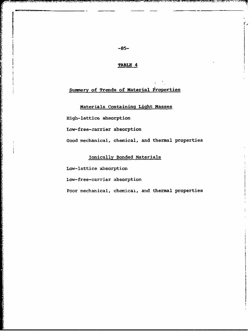
-85-
TABLE 4
Sununary of Trends of Material 1roperties
Materials Containing Light Masses
High-lattice absorption
Low-free-carrier absorption
Good mechanical, chemical, and thermal properties
Ionically Bonded Materials
Low-lattice absorption
Low-free-carrier absorption
Poor mechanical, chemical, and thermal properties

-86-
(A summary of advantages and disadvantages of
r these materials, to be discussed below, was given in
Table 4.)
Other candidates, considered to be less likely
for the near term than the above, are:
GaSb, ZnTe, CdSe, (Ca,Sr,Ba) (Se,Te).
The symbol (Ca,Sr,Ba) (Se,Te) means the set of materials
CaSe, CaTe, SrSe, SrTe, BaSe, and BaTe.
B. Absorption at 10.6mm of Ge, GaAs, ZnSe, and CdTe
Materials containing heavy elements generally
will not be acceptable for use at room temperature because
the size of the electronic band gap E decreases with& *g
increasing mass and a small value of E gives rise togfree--carrier absorption, as discussed in Chapter IV. On
the other hand, the masses should be heavy in order to
keep the lattice absorption small. The four heaviest
IIB-VI materials with E > 0.7eV are (Zn,Cd)(Se,Te). Ofgthese four materials, ZnSe and CdTe are chosen as the
most promising for the near term since their properties
are better known.
The lowest value of the absorption coefficient
measured at 10.6Mm to date for ZnSe (chemical vapor(2)deposited) is
-iB = 0.005 cm
.
With this value of 8, a 1-cm-thick sample of ZnSe can
transmit 103 J/cm2 in the pulse mode of operation.

-87-
The lowest value of 0 reported to date for CdTeis(3)
1.5x10⁻³ -1
which is believed to be larer than the intrinsic value.
With this value of 0, a 1-cm-thick sample of CdTe can
transmit 860 J/cm 2 in the pulse mode of operation.
The two heaviest III-V materials with E > 0.7eVgare GaAs and GaSb. The former is chosen as the most
promising of the two for the near-term since more informa-
tion is available on GaAs. With the smallest reported
value of 8 for GaAs(4)- -1
~=5xl0 cm
a 1-cm-thick window of this material can transmit 190
J/cm 2 in the pulse mode of operation.
Ge previously was considered unsatisfactory
because of thermal runaway (2'4'5 ) (E = 0.7eV), which
occurred at a temperature somewhat above room temperature.
However, the allowed temperature rise in the window is
severely limited by the thermally induced optical distor-
tion; the allowable center-to-rim temperature defined inEquation (111-7) is AT = 0.50C. Furthermore, the
thermal runaway problem could be avoided by operating the
window below room temperature. Thus, it appears that
thermal runaway will not prevent the use of Ge as a high-
power-window material in some applications.
The minimum value of 8 for Ge reported to date
+f =2xi0 2 -3 -i -2 -1fc =+xl cm =2.5xi0 cm
t-88-
where Bfc and 0.. are the contribution from carriers and-other sources, respectively. This Raytheon result was for
a 20 ohm-cm n-type sample. which showed the smallest value
-Io fc (= 0.005 CM ) as a function of resistivity. Intrinsicof~~~samples showed a larger value of f-O0 cm The
Raytheon results suggest that it may not be possible to
reduce the room temperature value of Bfc below 5x03cm
but that a substantial reduction in the value of Bfc can
be obtaired with a modest reduction in temperature, say to
2700K. The fact that the values of B _, for the Raytheon~p=samples varied considerably with the impurity level suggests
that the intrinsic value of 0 may be smaller than the
lowest Raytheon value of B - 2xl02 cm- 1
Ultrapure inch-size ingots of germanium with
intrinsic room-temperature prcperties recently have become
available on a limited basis. (7)if these samples have
small values of p_, germanium will be a good candidate
material, as discussed further in Section J. If a value-3l-
of 0 = 5x10 cm is obtained, a 1-cm-thick sample of
germanium can transmit 150 J/cm 2 in the pulse mode of
operation.
C. Discussion of Other Semiconductor Materials
The material GaSb (E = 0.7ev) was consideredg
unsatisfactory because of the potential thermal-runaway
problem. (5)Since large temperature rises are not allowed,
as discussed above for Ge, GaSb could be considered
further in a long-term program.
The properties of the IIA-VI compounds (Ca, Sr,
Ba) (Se,Te) are not as well known as those of the IIB-VI
compounds above, although the properties of the two types(8)
of materials probably are not too different. The IIA-VI
materials have the NaCL structure and have larger electro-
negativity differences than the corresponding IIB-IV
materials, which indicates that they have a higher 4egree
of ionic bonding than do the IIB-VI materials. BaSe is
known to be hygroscopic. (9)The v:.-lue of E for BaTeg
probably will not be too small since BaTe has the NaCL
structure.
Finally, consider the reasons for eliminating
many well-known semiconductor materials. The small values
of E for Sn, Pb, (In, TL)(As, Sb, Bi), and HgTe aregexpected to make these materials unacceptable for room
temperature use. Some of these materials could be useful
at lower temperatures. The light effective masses of
(B, Al) (N, P, As, Sb, Bi), (Ga, In, T) (N, P), (Be, Mg, Ca,
Sr, Ba, Zn, Cd, Hg)(0, S), and (Be, Mg)(Se, Te) make these
materials unlikely candidates for use at 10.6Am.
D. Scattering
Scattering in low-0 single crystals should be
checked experimentally.
E. Mechanical Strength
Values of the tensile strength of single crystals
of Ge, GaAs, ZnSe, and CdTe are listed in Table 5. The

F -89 (a) -
vi 0% MV mV mV12 IV N4 0 tn 0% %o H H H 0 H mn tn
1 MA H N
00 0 0 C0 0 0
44 ~ ~ H N HD k NL H
Cen 0- -n 54e4 (D 41 l .
0 ) 4
., >I N 0HH
) 04 CO H 4 c c r$4 ) _ _ _ _ 44_ _ _ _ _
>t- j Io I 1 I
U) 4 o 0 0 0 0 11 0-4) (a 7j. H- Ht m~ H H Rn
rc rd4 H 1
r. I I m r
) 4D o en en 0 x 0 c4-) -P (D 4 H H I -H
0 X 0 in x I Ir. i H H in
(12 a) 1 00u W 0 N 4t
CN tn LN U C)
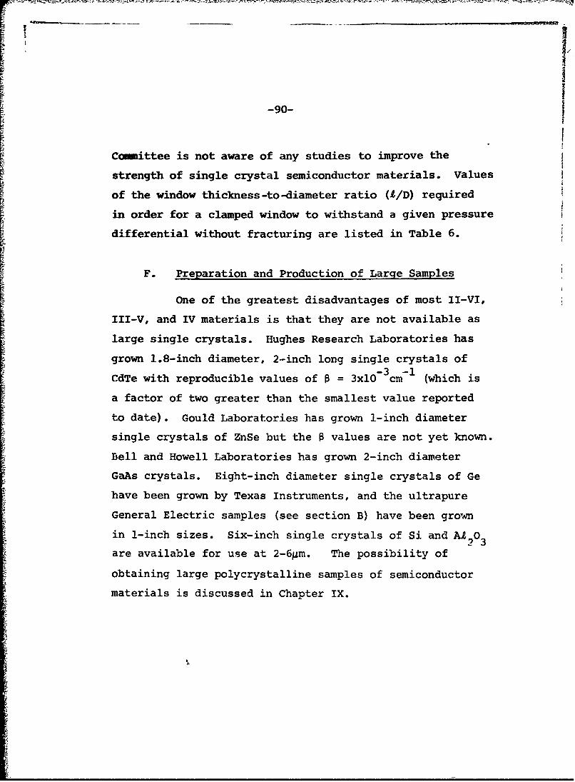
-90-
Committee is not aware of any studies to improve the
strength of single crystal semiconductor materials. Values
of the window thickness-to-diameter ratio (A/D) required
in order for a clamped window to withstand a given pressure
differential without fracturing are listed in Table 6.
F. Preparation and Production of Large Samples
One of the greatest disadvantages of most II-VI,
III-V, and IV materials is that they are not available as
large single crystals. Hughes Research Laboratories has
grown 1.8-inch diameter, 2-inch long single crystals of-3 -lI
CdTe with reproducible values of 0 = 3x10 cm (which is
a factor of two greater than the smallest value reported
to date). Gould Laboratories has grown 1-inch diameter
single crystals of ZnSe but the 0 values are not yet known.
Bell and Howell Laboratories has grown 2-inch diameter
GaAs crystals. Eight-inch diameter single crystals of Ge
have been grown by Texas Instruments, and the ultrapure
General Electric samples (see section B) have been grown
in 1-inch sizes. Six-inch single crystals of Si and A103
are available for use at 2-6gm. The possibility of
obtaining large polycrystalline samples of semiconductor
materials is discussed in Chapter IX.
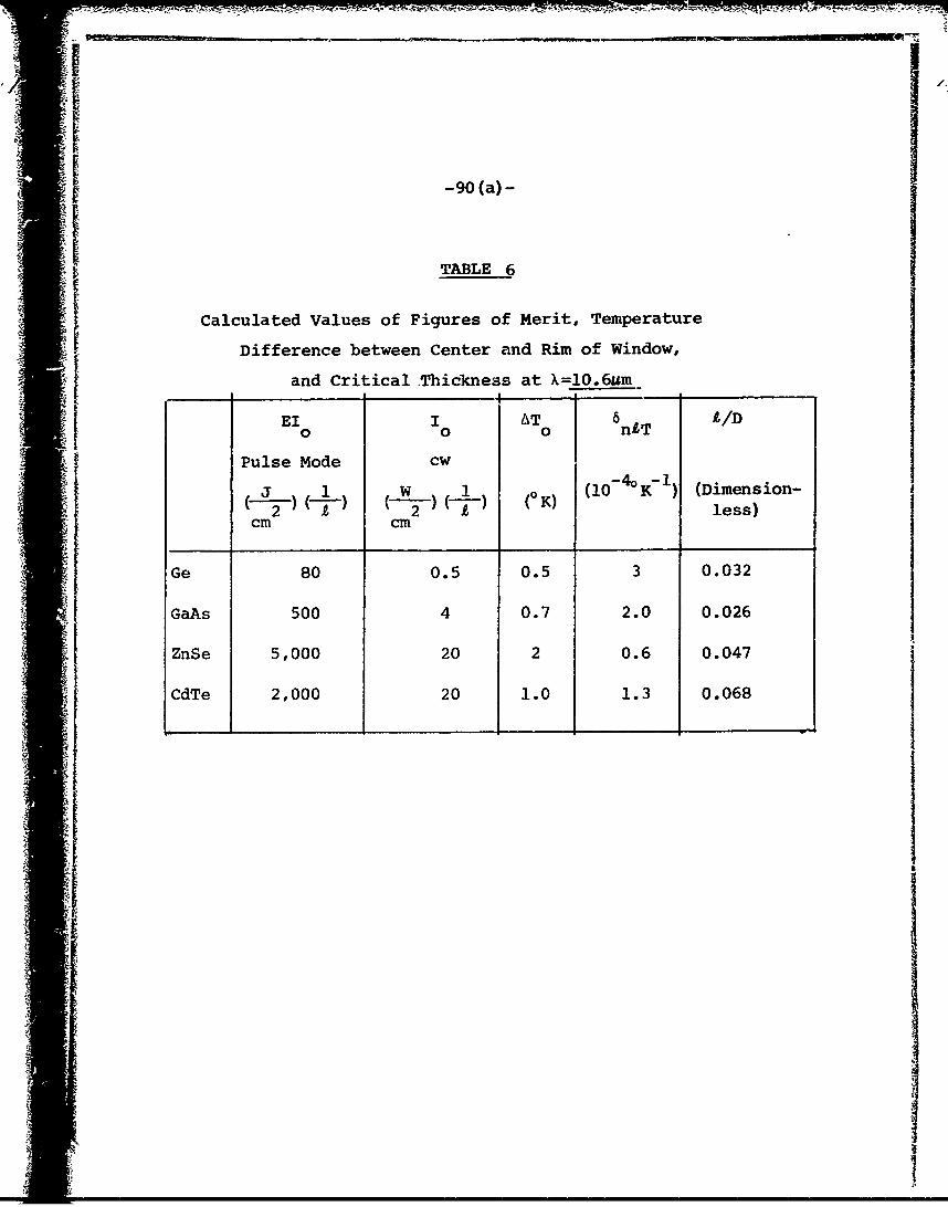
-90 (a) -
TABLE 6
Calculated Values of Figures of Merit, Temperature
Difference between Center and Rim of Window,
and Critical .Thickness at X=10.6um
0 - 0EI0 I 0AT 6nlT I/D
Pulse Mode cw(__ 1 (W 1_ ) (K (10-4K 1 (Dimension-
2' 2 less)cm cm
Ge 80 0.5 0.5 3 0.032
GaAs 500 4 0.7 2.0 0.026
ZnSe 5,000 20 2 0.6 0.047
CdTe 2,000 20 1.0 1.3 0.068

-91-
G. Surface Coatings
The Committee knows of no previous experimental
investigations of anti-reflection or protective surface
coatings for II-VI, III-V, or IV materials for high-power
infrared use. A theoretical study of the heating of
windows by absorption in a surface coating has been made.(10)
Anti-reflection coatings are especially important for
semiconductor materials since their large values of the
index of refraction give rise to large reflection losses.
Moisture protective coatings should not be required.
H. Figures of Merit
Values of the figures of merit for the semi-
conductor materials of interest are listed in Table 6 for
10.6Mm operation and in Table 7 for 4Mm operation, and a
brief general discussion of figures of merit was given in
Chapter III. The small values of I in the cw case indi-0
cate that for high-power applications the semiconductor
materials will be most useful in the pulse mode of operation.
I. Outlook at 2-6gm
The problem of finding suitable materials for
high-power-infrared windows in the 2-6Mm range is consid-
erably simpler than for the 10.6Mm range, since lighter
element materials with their generally superior mechanical
and thermal properties can be used in the 2-6Mm range and
still have small values of 8. In addition to the materialsdiscussed for use at 10.6Am, the II-VI, III-V, and IV

1!
-91 (a)- fI!
TABLE 7
Calculated Values of Figures of Merit, Temperature
Difference between Center and Rim of Window,and Critical Thickness at XA4m
EI I AT " AID0 0 0 A
Pulse Mode cw
----, 1 (0 K) (10 -4oK 1 (Dimen-2 ) (i ) -i )sion-
Cm c less)
Ge 200 1.4 0.2 3.2 0.032
GaAs 130 1.0 0.3 1.6 0.026
CdTe 700 6 0.4 1.2 0.068
Si 800 5 0.4 1.4 0.039
MgO 1.2x10⁴ 40 1.9 0.26 0.026
At203 1,300 4 3 0.16 0.014

-92-
materials commonly considered for use at 2-6&m are Si and'
MgO. Sapphire (At203) also is considered as a good candi-
date. Figures of merit for these seven materials are
listed in Table 7. There are many other materials such as
other oxides, sulfides, phosphides, and compounds of At
and Mg that should be investigated systematically, as
discussed in Section J.
It should be mentioned that the near- 2 depen-
dence of the free-carrier absorption should make the free-
carrier absorption in Ge much less of a problem at 2-6Am
than at 10.6Mm. However, it is conceivable that interband
scattering in germanium and other semiconductors could limit
their usefulness in the 2-6m range. If this turns out to
be the case, the common belief that a material that is good at
10.6gm will be even better for 2-6Mm operation is not
correct in general for semiconductor materials.
J. Optical-Absorption-Coefficient Study
It is believed that most, perhaps all, of the
10.6pm values of the optical-absorption coefficient,8,of
the candidate materials discussed in the present report
are larger than the intrinsic values. In order to evaluate
the potential of candidate materials, it is important to
know or at least to have estimates of the intrinsic value
of 0. This is especially important since expensive
imperfection-identification and sample-purification pro-
grams should be undertaken only if there is a good chance
of reducing the value of 0.

-93-
The value of the multiphonon contribution to 8
as a function of w in semiconductor materials shows syste-
matic trends in going from the two-phonon to the three-
phonon region and to higher-phonon regions. At sufficiently
large values of w, it is expected that the imperfection
contribution to 8 will appear as a deviation from this
trend. The temperature dependence of 8 might assist in
identifying the onset of the imperfection process and
should be studied further.
Assuming that the relatively smooth exponential
or power-law behavior of 8 as a function of w for the
ionically bonded alkali halides and MF2 crystals discussed
in Chapter IV are characteristic of the intrinsic absorp-
tion, the onset of the imperfection process should be even
easier to identify in these crystals than in the semicon-
ductors. In order to identify and reduce the imperfection
contribution to 8, both ultrapurification and intentional-
doping programs of carefully selected materials should be
useful.
K. Recommendations
CdTe, ZnSe, GaAs, and Ge Programs. The value of
8 of the ultrahigh purity General Electric samples of
germanium should be measured. This could be done at no
cost in an existing program. Scale-up studies sbould not
be started until an acceptable value of 8 is demonstrated.
The present effort to lower the absorption of
small-size ZnSe and CdTe crystals, b.oth in singl6-crysta:

I
~-94-
form and by chemical vapor deposition techniquest should
be continued. A total effort of 4 man-years over the next
2 years is recommended at an estimated cost of $300,000.
Gallium arsenide should be studied in the program
discussed in Section J before further purification or
scale-up programs are undertaken.
Anti-reflection coatings are especially important
for these high-index materials and should be studied. (See
Recommendation 5 in Chapter II.)
A1

-95-
REFERENCES
1. M. Sparks, Physical Principles, Materials Guidelines,
and Materials List for High-Power-10.6am Windows.
The Rand Corp., R-863-PR, Contract F44620-67-C-0045,
March 1972.
2. V. L. Donlan, Air Force Materials Laboratory,
Dayton, Ohio. (Private commuication)
3. Ricardo C. Pastor, Hughes Research Laboratories,
Malibu, California. (Private communication)
4. F. A. Horrigan and T. F. Deutsch, "Research in Optical
Materials and Structures for High-Power Lasers,"
Raytheon Research Division, Final Technical Report,
Contract DAAHO1-70-C-1251, (September 1971), p.105.
5. F. A. Horrigan and R. I. Rudko, "Materials for High-
Power-CO Lasers," Raytheon Research Division, Final2
Technical Report on Contract No. DAAHOI-69-C-0038,
May 1969;
----------- , C. Klein, R. Rudko, and D. Wilson,
"Microwaves,"Laser Technology Section, (January 1969),
p.68.
, et al. "High-Power Gas-Laser Research,"
Raytheon Research Division, AD676-226, Final Technical
Report on Contract No. DAAHOI-67-1589, (September 1968).
6. M. Sparks, J. Appl. Phys. 42, 5029 (1971).
7. R. N. Hall, General Electric Research and Development
Center, Schenectady, New York. (Private communication)

-96-
8. A. Chase, Ae-ospace Corp., El Segundo, Califorpia.
(Private communication)
9. P. Macedo, Catholic University, Washington, D.C.
(Private communication)
10. M. Sparks, Calculated Temperature Distributions in
Slabs Heated in a Thin Surface Layer, TM3,
Contract F19628-71-C-0142, Parke Mathematical
Laboratories, Inc., Carlisle, Massachusetts,
(September 1971).

-97-
VIII. CHALCOGENIDE GLASSINFRARED-WINDOW MATERIALS
A. Homogeneous Chalcogenide Glasses
1. Introduction
In one sense homogeneous chalcogenide glasses
based on the heavier members of the oxygen family may be
considered homologues of oxide network glasses in which
the lighter elements [B(III); Si(IV); 0(11)] are replaced
by the corresponding heavier elements [As (III) or Sb (III);
Ge(IV); S(II), Se(II), or Te(II)]. The analogy is borne
out in the structures of a number of the stoichiometric
compositions, GeS having a tetrahedrally coordinated2
three-dimensional-network structure similar to that of
SiO 2, and As2S 3 and As 2Se3 having two-dimensional-layer
structures analogous to (but not identical to) that of
B203. Plumat (1) has noted that GeS2 alkali sulfide and
GeSe alkali-selenide melts appear to form phase-separated2
glasses, in much the same fashion as SiO 2 alkali-oxide melts.
On the other hand, there exists also a reason-
able analogy between chalcogenide glasses and organic
polymers, the individual atoms of the chalcogenide glass
fulfilling the role of monomeric units. For instance,
elemental S or Se glasses are similar to organic chain
polymers, As 2S3 and As2Se3 to two-dimensionally cross-
linked sheet polymers, and GeS 2 to a three-dimensionally
cross-linked-network polymer. As is 3xpected from this
analogy, the glass transition temperatures of chalcogenide
-98-
glasses increase with the "degree of cross-linking" (2,3)
as shown in the series polymeric S (Tg = 270C), As2 S3
(Tg = 1850 C), and GeS2 (Tg = 4900C). Because of the small
differences in electronegativity between the constituent
elements, chalcogenide glasses do not follow the sort of
stoichiometric rules that tend to keep the B:O or Si:O
ratios fixed in oxide glasses. Rather the number of com-
ponents in the chalcogenide glass must be taken to be the
number of different elements, in line with the polymer
analogy using the atoms as monomeric units. Thus arsenic
and selenium combine to give glass-forming melts over the
large composition range Se to As 61Se39 (4) (subscripts refer
to atomic percent), although glasses between Se and
As 40Se60 are suspected of being phase-separated. (5) Wo
good examples of studies of structural variations of
chalcogenide glasses over composition ranges of this sort
may be found in the papers of Tsuchihashi and Kawamoto on
the As-S (6) and the Ge-S (7)systems.
Oxide-network glasses are most frequently ionic
conductors, the electrical conductivity of even te pure
"network formers" such as Si0 2 or B203 being due to
impurity alkali ions or protons. Plumat (1) has presented
some evidence for ionic conduction in GeS 2 alkali-sulfide
glasses, but other chalcogenide glasses are almost
inevitably electronic semiconductors, including such
glasses as those formed from T 2Se-As 2Se ,which bear a
formal resemblance to thallium-borate glasses.

-99-
In the following sections those properties of
homogeneous chalcogenide glasses important for use as
infrared windows, particularly at the CO2 laser wavelength(8) 2of 10 .6gm are reviewed. (Hilton has published a recent
review on this subject; the somewhat older review ofSSavage and Nielsen (9) is also of considerable utility.)
For reference in the sections to follow, we list in Table 8
important properties of three IR-transmitting homogeneous-
chalcogenide glasses: As2 Se3 , probably the most widely
studied chalcogenide glass, and Ge28Sb12Se60 and Ge33As1 2Se55,
two high-softening-temperature glasses developed by Texas
Instruments Corporation for possible conmercial use.
2. Infrared Absorption
Barring for the moment impurity bands (water in
oxide glasses, trace oxides in non-oxide glasses), the
boundaries to the infrared window in network glasses aregenerally determined on the high-frequency side by theelectronic charge transfer absorption edge and on the low-
frequency side by overtones of the nearest neighbor
vibrational band (the reststrahl band). The IR window
spans roughly the wavelength range 0.2 - 3pm for oxide
glasses, 0.6 - l1m for sulfide glasses, 1 - 15m for
selenide glasses, and 2 - 20Mm for telluride glasses. The
shifts of both of the IR-window edges to longer wavelengths
with increasing atomic mass are in accord with simple
predictions based on the effects of increasing atomic mass

-99(a)-
TABLE 8
PHYSICAL PROPERTIES OF HOKOGENEOUSCHALCOGmIIDE IR-TRANSMITTING GLASSES
_Glass
As2Se3 Ge28 b12 Se60 Ge33"12 Se55Property* (TI-1173) (TI-20)
Transmission Range film) 1-15a 1-16a 1-15 a
Refractive Index, 5Om 2.79b 2.62a 2.49a
Temperature coefficient ofindex of iefraction, -
6 aA AT K- . 80xi0-6 -
Absorption coefficient, 0
(cm - 1) @ 10.6gm** 0.01c 0 .0 3 d 0.02 e
Density P(S/cm 3 ) 4.54-4.68 f - .. 4.61
d 4.40 e
Linear coefficient of
thermal expansion,cGK-1__l _ 21x1O- 6 j 15,,10-6 a 13x10-6 e
Softening point (0C)*** 236k 326a 474 a
Glass Transition temperature,
Tg (0C)**** 1751 27 1m 353m
Specific heat,Cp (cal/g0 K) 0 .0 7 5i 'l 0 .06 5
m 0.071m
Thermal conductivity, K 7.7x10 1 f
(W/croOK) )2.9x10⁻³ 0 2.6x0-3 d -
Hardness, Knoop Scale ]14a 150 a 171 a
Young's modulus (psi) 2.6x10 4.2xi06 a 4.5x10⁶ a
Shear modulus (psi) 1.OxlO6 h -
Poisson's ratio 0 .30h -Rupture modulus (psi)a
(annealed) - - 2500 a
(thermally tempered) - - 7000-10,000
Resistivity (ohm cm) 1012 n ....
* Properties are those in the vicinity of 250C.** Lowest measured 0 known to author at time of writing.* At softening point viscosi.y is approximately 7.6 poise.**** Measured by DTA at heating rate of 200K/min.

-99 (b) -
Table 8 (continued):
Sources of Data
a) Reference 8
b) Reference 9
c) Reference 10
d) Reference 11
e) Reference 12
f) Reference 13
g) Reference 14
h) Reference 15i) Reference 16
j) Reference 17
k) Reference 18
1) Reference 19
m) Reference 20
n) Reference 21
o) Reference 29

-100-
on ionization energies (decreasing ionization energy
Sdecreases charge transfer band frequency) and on nearest
neighbor vibrational frequencies (Vvib r- , where it is
the appropriate reduced mass). Hence chalcogenide glasses
owe their excellei IR-transmission characteristics primarilyIto their high average atomic weights. The best of the IR-
transmitting-chalcogenide glasses to date have been based
on selenium, since, on the one hand, the selenide glasses
transmit substantially further into the IR than do the
sulfide glasses, while, on the other hand, selenide melts
are considerably better glass-formers than the more
metallic telluride melts.
Shown in Figure 10 are IR-transmission spectra of
As2 Se3 glass and a high-softening temperature Ge-As-Se
glass taken from the paper of Savage and ;±elsen.(9) The
two impure glasses each contain about 500 ppm of oxygen
contaminant. As is evident from the figure, a small
amount of oxygen impurity causes a drastic deterioration
in the IR-transmission characteristics of selenide alasses
at wavelengths longer than 8gm. The principal absorption
at the CO laser wavelength of 10.6Mm is seen to arise2
from the tail of an oxide impurity band centered in both
glasses around 13Am. (The smaller inpurity bands at
around 9.5 and 8Mm for the two respective glasses are
probably combination bands of the reststrahl band and the
13gm oxygen band.) Rough estimates of the absorption
coefficients, 8, at 10.6Mm due to the oxide impurities
for the two glasses of Figure 10 yield:

-' .... . .. A:
-100 (a)-
100)
Figure 0. Teifa dt rs ission f uifeselenie glaseOxiTe doaseuvsso
a h bondsybads
(a) As 40 Se 60 specimen thickness 0.175 cm.(b) Ge As Se specimen thickness 0.180 cm.
3 58
As2Se 0 /pp:o - 5xl0-c - ppmO - 1 ,2 3 /pO5l cm pO
-3 -1 -1Ge 34AsSe 5glass 0 /ppmO -5xl0 cm ppmO o
Similar estimates can be obtained from the data of Vasko,
Leval, and Srb. (22)It appears that the presence of Ge
leads to a ten-fold increase in O/ppmO in selenium-based
glasses at 10.6Mm. This is most likely due to the fact
that Ge forms the most stable bonds with oxygen of the
three elements,Ge, As, Se, so that the oxygen present in
the glass bonds preferentially to Ge atoms. (23)At the
same time, the higher Ge-O-bond energy leads to a larger
force constant for the Ge-0 vibration, which, in turn,
enhances the absorption at shorter wavelengths. This is,
of course, rather unfortunate, since, as will be detailed
below, Ge is a highly desirable component of chalcogenideglasses in terms of improving their mechanical and thermal
properties. On the basis of the above figures, the maxi-mum oxygen content allowable if 0 is to be kept below
10 cm 1 is around 2 ppm for As-Se glasses and around
0.2 ppm for Ge-As-Se glasses.
Hilton and Jones (23)and Savage and Nielsen(24)
have published studies of the sources of oxygen contamina-tion and their remedies in chalcogenide glasses. Chalcoge-
nide melts for glass production are commonly synthesized Ifrom the elements under vacuum in sealed Pyrex, Vycor, or
fused silica containers at temperatures ranging from 350
to 1000 C. The most likely sources of oxygen in the glass
are:

I
-102-
a) oxygen or water impurities in the elemental
starting materials,
b) oxygen or water adsorbed on the surface of the
containment vessel,
c) reaction with tne oxide glass containment vessel.
At the present no really firm criteria are
available for assessing the minimum oxygen content attain-
able in a reasonable synthesis of chalcogenide melts.
Past efforts to minimize oxygen contents have included:
a) handling and heating of materials under inert
gas or vacuum,
b) prepurification, including reduction in a hydrogen
atwosphere, of the elemental starting materials,
c) baking out of silica containment vessels under
vacuum to remove adsorbed water prior to the
synthesis, (24)
d) distillation of the melt, (24)
e) reduction of synthesis temperature to reduce the
extent of the (probably endothermic) reaction of
the melt with the oxide glass containment
vessel, (25)
f) chemical scavenging of the melt by treatment
with or addition of relucing agents such as
hydrogen, carbon, magnesium, beryllium, and
aluminum. (12,24,26)
Most of these procedures were aimed primarily
at reducing the infrared absorption due to oxide impurities
to a level well below the reflection losses (around 30-40
-103-
percent) at the sample surface, but not necessarily to a
level well below the inherent absorptivity of the oxygen-
free materials. A substantial amount of research is
needed in this area, since until oxygen-free glasses are
obtained, the contributions to the IR absorption of
chalcogenide glasses from other sources (free-carrier
absorption or multiphonon processes) cannot be assessed.
As an example, the purified As2Se3 glass spectru of
Figure J.0 exhibits a noticeable shoulder (which has been
observed at a number of laboratories) at around 15Mm, the
tail of which appears to be the main source of IR absorp-
tion at 10.6gm. This 15Mm shoulder may arise from
residual oxide impurities in the As 2Se3 glass. On the
other hand, values of the reststrahlen frequency for the
As-Se vibration in As Se reported from three independent2-1 (25) -1 (27) -1 (28)
laboratories are 228 cm , 217 cm , and 237 cm- .
The first overtone of the reststrahl band i /2v r 22Mm)r
is prominent in Figure 10, and the second overtone
(1 /3v r 15Mm) may well account for the 15Mm shoulder in
the purified As 2Se3 glass.
As shown in Table 8, the lowest 10.6Mm absorption
coefficient obtained for chalcogenide glasses is on the
order of 10-2cm . Whether this value can be lowered by
more stringent oxygen removal techniques or whether ,it is
set by multiphonon processes inherent to the bulk glass
remains to be determined. In the event that absorption at
10.6Am in the glasses so far studied is due to multiphonon
processes (overtones of the reststrahl band), it also
remains to be determined whether the absorption coefficient
can be reduced by changes in the glass composition.

-104-
3. Scattering
Scattering is not expected to be a proele with
homogeneous chalcogenide glasses.
4. Mechanical and Thermal Properties
As noted in Section 1, the most highly cross-
linked homogeneous chalcogenide glasses,(i.e.,those con-
taining substantial proportions of quadrivalent elements
such as Si or Ge) are also those which exhibit the highest
glass-transition temperatures and softening points. As
may be seen by comparison of the properties of As 2Se3 with
those of the germanium-containing glasses of Table 8, and
as detailed in the review article of Hilton, Jones, and(30).
Brau, increases in the Si or Ge content of homogeneous
chalcogenide glasses also correlate strongly with increases
in the mechanical and rupture moduli and Knoop hardness and
decreases in the thermal expansion coefficient.
Given in Table 9 are some typical mechanical and
thermal properties for oxide-network glasses. Comparison
with Table 8 shows that the best homogeneous chalcogenide
glasses developed to date (Ge 28Sb 12Se60 and Ge 33As 12Se 55)
are markedly inferior to typical oxide glasses in strength
and upper use temperature (which is set roughly by the
glass transitiox. temperature, Tg).
Thermal conductivities near room temperature of
selenide glasses determined by two laboratories (11,29)
seem to fall fairly regularly in the range K - 0.002 -
0.003 W/cm0 K, with no significant changes in-K perceptible

-104(a)-
TABLE 9
MECHANICAL AND THERMAL PROPERTIES
OF TYPICAL OXIDE GLASSES
Linear coefficient of
thermal expansion, (OK-) 8-9xi0- 6
Glass transition
temperature, Tg (°C) 500
Hardness, Knoop scale 300 - 600
Young's modulus (psi) 7-I~x106
Rupture modulus (psi)
(annealed) 5000
(thermally tempered) 15,000 - 20,000
(chemically strengthened) 100,000

-105-
due to changes in the degree of cross-linking of the glass.
Russian investigators, (13) however, have measured K values
for the same types of glasses which are 2 to 3 times larger
than those reported above.
Specific heats of chalcogenide glasses in the
temperature range -1000C up to the glass transition tempera-
ture are closely approximated by the Debye heat capacity(19,20)function. For selenide glasses, for instance, the
specific heat may be estimated to within a few percent by
the formula
Cp (cal/g°K) = C(T/Od), (VIII-l)P d
M
where C(T/Od) is the Debye heat capacity per gram-atom for
reduced temperature T/ed, (31)M is the average atomic weight,
and ed is the Debye characteristic temperature, which may
be taken as around 375°K for selenide glasses. (19,20)
5. Production of Large Samples
Scale-up for production of large pieces of melt-
cast glass is generally not a major problem, although
chalcogenide glasses present some difficulties in that the
melt" - , casting, and annealing processes must be carried
out in an oxygen-free environment to avoid contamination
of the glass. Because they are easy to produce in large
pieces, chalcogenide glasses possess a major advantage
over melt-grown single crystals or hot-pressed polycrystalline
materials. Texas Instruments Corporation is now capable of
-106-
supplying their Ge2 8 Sb1 2 Se 6 0 glass in 12-inch by 24-inch
plates.
6. Surface Coatings
Because of their high indices of refraction
(x 2.5 - 3.5), chalcogenide glasses exhibit high surface-
reflection losses (30-40 percent) at IR wavelengths.
Consequently, their use as IR windows will require the use
of anti-reflection coatings. On the other hand, chalcoge-
nide glasses are generally unreactive with water and
resistant to atmospheric oxidation at temperatures near
and below 250 C, so that no surface protection from water
or atmospheric attack is required for them.
7. Radiation Damage
To this Committee's knowledge, no studies have
been made of the effect of ultraviolet, x-ray, or nuclear
radiation damage in/on IR-transmission-chalcogenide glasses.
Chemical bonds in chalcogenide glasses are weak and it is
to be expected that energetic radiation would give rise to
extensive disruption of the glass network bonds, followed
probably by rearrangement of the local structure. Such
rearrangement would undoubtedly result in localized changes
in the density and in inhomogeneities in the refractive
index of the glass, particularly at the surface where most
of the hard radiation would be absorbed. Whether these
refractive-index inhomogeneities would be of sufficient
amplitude and dimension to adversely affect the IR
transmission in the 10Mm range remains to be determinedexperimentally.

-107-
8. IR Transmission at 2-6um
The 2-6pm region is the optimum transmission
region for chalcogenide glasses, being well removed from
absorption bands both of the bulk glass and of oxideimpurities (see Figure 10). The only known absorption
bands in this region that have been detected in chalcoge-
nide glasses are thought to arise from H2S or H2Se
impurities introduced during treatment of the melt with
hydrogen to remove oxide impurities. (23,24)
B. Chalcoqenide Glass-Ceramics
1. Introduction
In addition to the absorption at 10.6pm due to
oxide impurities, homogeneous chalcogenide glasses possess
a number of inherent drawbacks to their use as high-energy
IR-laser-exit windows, namely, low strengths, low thermal
conductivities, and high coefficients of thermal expansion.
In this section the feasibility of producing a new variety
of material suitable for use as a laser-exit window will
be discussed. This chalcogenide ceram offers the possi-
bility of combining the superior thermal and mechanical
properties of polycrystalline metallic chalcogenides with
the ease of fabrication (melt-casting of large window
I

!/2
-108-
2. Structure of Glass-Ceramics
Glass-ceramic or ceram is the generic name for a
material that is melted and formed as a glass and then
almost completely crystallized during a subsequent heat
treatment. (32-34)The most characteristic feature of the
ceram is that the crystals are minute and of uniform size.
This is achieved by selecting a base glass which exhibits
liquid-liquid immiscibility above the glass transition.
If the base glass is chosen near the center of the immis-
cibility dome, the two immiscible phases will have roughly
equal volume fractions, and the glass microstructure will
be of small dimension and exhibit a high degree of inter-
connectivity. Provided that the glass viscosity remains
sufficiently high, no appreciable growth of the size of
the phase-separated microregions will occur during the
subsequent heat treatment leading to nucleation and crystal-
lization of one of the phases. The inter-connected struc-
ture will block growth of the crystals beyond the boundaries
of the region undergoing crystallization, so that a fine
dispersion of small crystals of uniform size will result
from crystallization of the first phase. A follow-up heat
treatment can then result in partial crystallization of
the second phase, so that the final product, i.e., the
glass ceram, consists of 80-90 percent crystalline material
imbedded in a glass matrix.
Iji
-109-
3. Properties of Glass-Ceramics
Oxide glass-ceramics have been formed which are
transparent in the visible region. For glass-ceramics
in which the crystal volume is a large fraction of the
total volume, we do not have a closed-form expression for
the attenuation coefficient, 8. However, the predictions
of Rayleigh scattering from spheres (38can give us the
qualitative dependence of 0 on the size, refractive index,
and number per unit volume of crystals for the glass-ceramic.(35,36)
For the oxide glass-ceramics transparent in the visible,
the average crystal size was around 0.1Mm so that trans-
parency to light of wavelength 0.5-0.8Mm was a result of
both small crystal size and a close match between the
indices of refraction of the crystals and the glass matrix.4
The attenuation coefficient goes inversely as X4, so for
light of wavelength 10mwhich must be transmitted by the
chalcogenide glass-ceramic, the index of refraction match
will not be as critical, provided that the crystal size
can still be kept at or below 0.1Mm, and infrared trans-
mission losses by scattering from crystals in the material
should be tolerably small.
The chalcogenide ceram would share the advantage
of the homogeneous chalcogenide glasses in that up-scaling
the production process to product large samples is a
relatively minor problem. The glass-ceramic is initially
cast from the melt in one piece as a phase-separated glass
and is crystallized subsequently by heat treatment of the
entire blank.

-110-
I]The ceram possesses several material advantages
over comparable single-phase homogeneous glasses. The
upper use temperature for homogeneous glasses is the glass
transition temperature. For 80-90 percent crystalline
glass-ceramics, barring other effects such as reavtion with
the atmosphere, the upper use temperature may approach the
melting point of the crystals (- 13500 C for CdSe, a
possible major component of ceram compositions presently
under consideration). The strength (abraded modulus of
rupture) of glass-ceramics is typically considerably
larger than the strength of comparable single-phase glasses.
In oxide materials the abraded rupture modulus is increased
from 1 kpsi for annealed glass to 10-20 kpsi for the glass-
ceramic. The small crystals of the ceram act as crack
tbrminators preventing build-up of large internal stresses
which lead to failure. Further surface treatments can
enhance the modulus of rupture values of both the glass
and the ceram, but for similar treatments the ceram
generally continues to enjoy its rupture modulus advantage
over the single-phase glass. For oxide cerams, modulus
of rupture values as large as 155 kpsi have been attained.
In addition, creep coefficients of cerams are exceedingly
small. The system is not rheologically simple in that the
ordinary processes of creep in crystals (grain boundary
diffusion in polycrystals, dislocation growth, and motion
in single crystals) are suppressed. Further, delayed
elastic effects, which can be a problem in glasses, are
severely restricted in cerams by the interconnected crystal
structure.

The improved mechanical strength of a chalcoge-
nide ceram would lead indirectly to an improvement in
optical properties with respect to single-phase chalcoge-
rnide glasses, since thinner windows could be used with the
ceram, which would lead to a corresponding reduction in
light absorption. In addition, the casting and heat
treatment of large samples becomes easier the smaller the
thickness.
When a composite material is 80-90 percent
crystalline, one obtains values for such properties as the
thermal expansion coefficient a, temperature coefficient
of refractive index dn/dT, and thermal conductivity K
that closely approach those in the pure crystal. Chal-
cogenide cerams are presently under development (37) in
which the crystalline phase would be principally a
metallic chalcogenide semiconductor such as PbSe or CdSe.
This represents a considerable potential improvement over
presently existing single-phase chalcogenide glasses,
since one wishes to maximize K and minimize a in the laser
window material. Some typical comparison figures are
given below:
Chalcogenide semiconductor a - 5xlO -6 deg
K - 0.1 watt/cm deg,
TI 1173 glass (Ge28Sb12Se60) a -16x10 -6 deg-1
K - 0.003 watt/cm deg.

, -112-
These iuprOVemnts in a and K can probably be realized
without any sacrifice in dn/dT, since the dn/dT values
are essentially the same for ZnSe or Cd~e crystals as for
the TI 1173 glass.
C. Suqested Areas of Research and Priorities
Because of the ease of fabrication of largepieces and the lack of reactivity with water, chalcogenideglasses and glass-ceramics should remain candidates forboth bulk material and coatings for the high-power CO2
isser window. Research should be continued on the assess-ment and improvement of these mate-ials, with emphasis onthe reduction of absorption due to impurities and other
sources. Anti-reflection coatings for the glasses shouldalso bu developed. An effort of 4 man-years over the next2 years at an estimated cost of $200,000 is recommended.
i

-113-
REFEPNCES
1. E. R. Plumat, J. Amer. Ceram. Soc., 51, 499 (1968).
2. S. A. Dembovsky, Phys. Chem. Glasses, 10, 73 (1969);
Izv. Akad. Nauk. SSSR, Neorgan. Hater, 5, 463 (1967).
3. X. B. Meyers and E. J. Felty, Hater. Res. Bul1., 2,
535 (1967).
4. S. S. Flaschen, A. D. Pearson, and W. R. Northover,
J. Amer. Ceram. Soc., 43, 274 (1960).
5. V. V. Tarasov, V. M. Zhadnov, S. A. Dembovskii, and
A. K. Malt'sev, Russ. J. Phys. Chem., 42, 1122 (1968).
6. S. Tsuchihashi and Y. Kawamoto, J. Non-Cryst. Solids,
5, 286 (1971).
7. Y. Kawamoto and S. Tsuchihashi, J. Amer. Ceram. Soc.,
,-4, 131 (1971); 54, 526 (1971).
8. A. R. Hilton, J. Non-Cryst. Solids, 2, 28 (1970).
9. J. A. Savage and S. Nielsen, Infrared Phys., 5,
196 (1965).
10. R. Mohr, C. T. Moynihan, and P. B. Macedo, The Catholic
University of America. (Unpublished data)
11. C. L. Strecker, Wright-Patterson Air Force Base.(Private communication)
12. C. E. Jones and H. Hafner, Texas Instruments, Inc.,
Tech. Rept. AFAL-TR-68-3-8, Contract No. AF33(615)-3963
(January 1969).

-114-
13. B. T. Kolomiets, L. Payasova, and L. Shtourach,
Soy. Phys.-Sol. St., 7, 1285 (1965).
14. J. Durcek, L. Rrivnak, S. Kolnik, C. Musil, and
F. Strba, J. Non-Cryst. Solids, 4, 66 (1970).
15. A. P. Chernov, S. A. Denbovskii, and S. F. Christov,
lzv. hkad. Nauk. SSSR, Neorgan. Mater., 4, 1449 (1968)
16. V. V. Tarasov, V. M. Zhadnov, A. K. Mal'ts, and S. A.
Dembovskii, Russ. J. Phys. Chem., 43, 249 (1969).
17. E. J. Felty and M. B. Meyers, J. Amer. Ceram. Soc.,
50, 335 (1967).
18. S. V. Nemilov and G. T. Petrovskii, Zh. Prikl. Khim.,
36, 977 (1963).
19. U. S. Schnaus, C. T. Moynihan, R. W. Gammon, and
P. B. Macedo, Phys. Chem. Glasses, 11, 213 (1970).
20. U. E. Schnaus and C. T. Moynihan, Mater. Sci. Eng.,
7, 268 (1971).
21. R. F. Shaw, W. Y. Liang, and A. D. Yoffe, J. Non-Cryst.
Solids, 4, 29 (1970).
22. A. Vasko, D. Lezal, and I. Srb, J. Non-Cryst. Solids,
4, 311 (1970).
23. A. R. Hilton and C. E. Jones, Phys. Chem. Glasses, 7,
112 (1966).
24. J. A. Savage and S. Nielsen, Phys. Chem. Glasses, 6,
90 (1965).

-115-
25. M. Onomichi, T. Arai, and K. Kudo, J. Non-Cryst.
Solids, 6, 362 (1971).
26. K. Liang and A. Bienenstock, Center for Materials
Research, Stanford University, ARPA Technical Rapt.
No. 1562, Contract No. DAHCO4-70-C-0044 (November
1971), pp. 74-78.
27. E. J. Felty, G. Lucovsky, and M. B. Meyers, Solid
State Commun., 5, 555 (1967).
28. P. C. Taylor, S. G. Bishop, and D. L. Mitchell,
Solid State Commun., 8, 1783 (1970).
29. C. J. Billian and J. Jergen, Jr., Servo Corp. of
America, Final Tech. Rept. Contract No. NONR 3647(00)
(2 January 1963).
30. A. R. Hilton, C. E. Jones, and M. Brau, Phys. Chem.
Glasses, 7, 105 (1966).
31. G. N. Lewis and M. Randall, "Thermodynamics," 2nd Ed.,
revised by K. S. Pitzer and L. Brewer, McGraw-Hill,
New York, New York, (1961), pp. 659-660.
32. S. D. Stookey, Ind. Eng. Chem., 51, 805 (1959).
33. P. W. MacMillan, "Glass Ceramics," Academic Press,
New York, New York, (1964).
34. J. F. MacDowell, Ind. Eng. Chem., 58, 38 (1966).
35. D. A. Duke and G. A. Chase, Applied Optics, 7,
813 (1968).

d
--" I
-116-
36. G. H. Beall and D. A. Duke, J. Mater. Sci., 4,
340 (1969).
37. P. B. Macedo, C. T. Moynihan, and J. J. Mecholsky, in
"Chalcogenide Glass-Ceramics as Potential Infrared
Laser Window Materials," Conference on High Power
Infrared Laser Window Materials, C. S. Sphagian and
C. A. Pitha, Eds., AFCRL-71-0592, (13 December 1971),
Special Reports No. 127, pp. 145-162.
38. Milton Kerker, "The Scattering of Light," Academic
Press, New York, New York, (1969), pp. 31-39.

I
~-117-
IX. POLYCRYSTALLINE INFRARED-WINDOW MATERIALS
A. Introduction
The potential of polycrystalline materials as
laser windows at 10.6prit and 2-6pm wavelengths is evaluated
in terms of absorption, scattering, mechanical properties,
preparation and scale-up production, surface coatings,
radiation damage, and program recommendations. Primary
emphasis is given to the 10.6gm wavelength range and in
this connection consideration is given to the II-VI, III-V,
and I-VII compounds, e.g., ZnSe, CdTe; GaAs; and KBr, KC1,
etc., respectively.
B. Polvcrvstalline Materials
1. Absorption
Chapters VI and VII of this report have already
discussed absorption in Group II-VI, III-V, and I-VII
compounds primarily treated as single crystals. The current
discussion is concerned with a treatment of these compounds
in polycrystalline form.
In general, other things being equal, one might
expect absorption to be always greater for a given com-
pound in polycrystalline form as compared to single-crystal
form for reasons given below:

~-118-
a) Free-Carrier Problem at Grain Boundaries
The increased dislocation density associated
with grain boundaries could conceivably increase the con-
centration of free carriers in compounds of the II-VI and
III-V category. Some experimental work is required to
confirm this, which involves measuring absorption in bothsingle crystal and Dolycrystalline samples with the latterprepared by the recrystallization of single crystals. In
this way, complicating extrinsic effects may be minimized.
For the I-VII compounds, however, free carriers
are not a problem.
b) Increased Impurity Concentration
This factor is likely to be greater in poly-
crystalline material prepared by normal particulate
processing methods; however, chemical vapor transport and
single crystal recrystallization processes offer alterna-
tive approaches to reduce the significance of this problem.
Selective distillation and melt-refining do make it possible
to further purify starting materials.
The presence of second-phase impurities and/or
solid solution additives can lead to increased absorption
at site locations, and unless methods are developed for
* A crystalline or amorphous material distinct from theprimary or host material.
w* An impurity material that enters the lattice of theprmary or host material, interstitially or substitutionally.
_4*
~-119-
preparing and handling raw materials with minimum contami-
nation, polycrystalline fabrication approaches are not
likely to be very successful.
2. Scattering
Bulk scattering of incident radiation in the
II-VI cubic polycrystalline materials is likely to be much
more dependent on residual porosity than on the presence
of grain boundaries. The presence of second-phase impuritieswould also present scattering sites, although these impur-
ities could be more significant in absorption..
In a recent effort on a Yttralox polycrystalline-
ceramic laser!)the influence of residual porosity on laserthreshold was well demonstrated. Levels of porosity of the
order 3x10- 5 percent to 10- 3 percent increased laser thres-
hold values from 30 joules to 50 joules with the best
attenuation of the order of 10- 2 cm-I
These represent about the lowest porosity values
reported for the case of a sintered polycrystalline ceramic,
yet there was still sufficient remanent porosity to sig-
nificantly reduce radiant transmission.
Scattering is likely also to be a problem with
II-VI and III-V compounds prepared by particulate approaches
where remanent porosity is an inherent feature.
* Polycrystalline ceramic- with cubic crystal structurecomprised of 90 percent Y203 and 10 percent ThO 2 or ZrO2in solid solution, produced at General Electric Company.

-120-
The mere presence of grain boundaries is not
likely to present scattering problems for such optically
isotropic materials as cubic I-VII halides and II-VI zinc
blend crystal structures unless birefringence results from(2) 2 2
process-induced strain whereby n = (n -1) (n+2) S.
6n2
The induced variation may be expressed in terms nf n, the
refractive index, and S, the induced strain. This is likely
to be a small effect in contrast to porosity and should be
capable of being annealed out. In addition, scattering as
a result of the presence of a second phase (likely to be
at a grain boundary) is a function of size, distribution,
and index of refractive difference. This second phase
would probably affect absorption more significantly.
3. Mechanical Strength
It is generally accepted that materials poten-
tially useful as laser windows in 1O.6sm region display
rather poor mechanical properties, particularly in terms
of tensile strength. In fact single crystals of such
materials (wherein the 3nergy to move dislocations is
rather low) can be significantly weaker than fine-grain-
size polycrystalline counterparts (because of dislocation
blocking). The difference in strength may be an order of
magnitude between the two. Strength can be increased still
further in polycrystalline material by coupling alloying
with grain size reduction.
In general, for brittle polycrystalline materials,
the strength increase has been observed to essentially
Ia

-121-
!(3)
follow the Griffith relation( '
Sf 1 , (Il-i)(G.s.)
= tensile strength
G.S. = grain size.
in this connection polycrystalline materials have
an inherent advantage over single crystals of current
interest.
4. Preparation and Production of Large Size Windows
A significant disadvantage of the II-VI and
III-V compounds is that they are not available as large
single crystals. As a result, the consideration of poly-
crystalline materials becomes important in view of the
relative ease by which large samples may be made. The
observed absorption coefficients of currently available
polycrystalline samples, however, are generally higher by
one to two orders of magnitude than those of corresponding
single crystals.
Four processes are worth discussing in this
connection and they include:
a) Standard Hot Pressing
This process has been employed to produce
the commercially available IRTRAN (Trademark Eastman Kodak
Co.) series of polycrystalline materials, e.g., ZnS, CdTe,
ZnSe. The hot-pressing process is currently supported by

-122-
(4)_a major DoD-sponsored progra' (4 involving preparation and
characterization of ZnSe and CdTe. The most significant
advantage in the hot-pressinr process is that the avail-
ability of large presses makes it feasible to scale-up the
size of windows. It is considered very difficult to prepare
material with adequate absorption coefficient, however.
Problems in contamination, resulting from powder synthesis.
handling, and consolidation, as well as in residual porosity,
remain to be solved.
This may be less of a problem for the I-VII
compounds than for the II-VI and III-V varieties, although
it is probably preferable to consider a forging process
for the I-VII compounds as described below.
b) Mechanical Working (e.g., Press Forging,
Rolling, etc.)
This process of slow compressive deformation is
probably most significant for the I-VII compounds primarily
as a means of raising the strength of high-purity single-
crystal samples. This is accomplished by recrystallizing
single crystals into fine-crystallite structure without
degradation of optical properties. By such an in situ
grain-boundary formation, associated second phases and
porosity, leading to absorption and/or scattering, are
minimized. An additional advantage is that the process
forms a larger diameter, short cylinder from a longer but
smaller diameter one, thus relaxing initial crystal diameter
requirements. The process has been successfully applied to
such materials as magnesia and alumina (5)as well as sodium
chloride. (6)

I
-123-
c) Sonic Casting
The development and application of this process(4)is currently sponsored under a DoD contract. It is a
modification of melt-growth single-crystal processes and
i-3volves sonically irradiating a melt, e.g.. CdTe during
solidification. The vibrations are believed to assist in
reducing the porosity of the casting, improve homogeneity,
and assist in developing finer grain morphology than
without vibratory casting.
The process has the advantage of being more
easily scaled-up to produce large size windows than single
crystal methods but difficulty in controlling resulting
grain sizes and pore removal rates are anticipated in any
scale-up operation. The process is currently being
evaluated for CdTe.
d) Chemical-Vapor Deposition
This technique has been demonstrated for ZnS and
ZnSe but has yet to be carried out successfully for CdTe.(4)
Chemical-vapor deposition offers potential scale-up and
the control of impurities by selective distillation.
Currently, it appears to be the most promising method of
polycrystalline material preparation aside from the
recrystallization of single crystals by mechanical working.
In this process, volatile compounds or other
volatile species of the materials to be deposited are
passed into the deposition zone of a furnace maintained at
a given temperature and pressure. The volatile compounds

-:1a
are directed to a substrate, e.g., pyrolytic graphite, and
are then allowed to thermally decompose and react at the
substr;te to form solid material. Typical deposition rates
are .005 to .010 in/hr. The reaction products are pumped
away and disposed of by scrubbing, etc.
The process has been successfully applied in
producing the purest ajiagle crystals of A2 0 3(7and
tgO(8) known.
4. Surface Coatings
No investigations of anti-reflection or protective
surface coatings have been published for the II-VI and
III-V compounds that have come to the attention of the
Committee.
Coating work has been started for I-VII compounds
and a combination of layers of BaF2 and vitreous As2 S3
looks promising.(9)
5. Radiation Damage
No investigations of the influence of radiation
damage to absorption behavior for the II-Vi, III-V, and
I-VII compounds have come to the attention of the Committee.
6. Outlook at 2-6gm
A whole range of meuhanic- ",, stronger and
environmentally more resistant compounds become worthy of
consideration in this spectral range.
These additional compounds to be considered
include such fluorides as MgF CaF2, BaF 2 , PbF as well2 2 2 2

I7
-125-
as other materials; e.g., Si, At2 03 , and MgO.
It is not likely that the preparation of suitable
polycrystalline samples of these compounds by particulate
processing, e.g., sintering or hot pressing, is any brighter.
Problems of pore removal and impurity contamina-
tion are still severe w±-h no apparent solution. The
chemical vapor deposition process as described in Section 3
does offer the potential of excellent impurity control as
cited for MgO and alumina and ZnSe. In these particular
instances, the products have been either single crystal
material or highly oriented polycrystalline material.
C. SHORT- AND LONG-RANGE-RESEARCH PLANS
The short-range probability of success in
developing suitable polycrystalline materials is not high
unless one considers the recrystallization of single
crystals by press forging (most suitable for large I-VII
alkali-halide crystals currently available). The motiva-
tion here is to improve the mechanical-strength properties
and a funding level of $100,000 is recommended.
In this connection, particular attention should
be given to evaluating press forging techniques applied to
I-VII compounds in single-crystal form, with emphasis on
resultant recrystallization, mechanical strength, and
optical properties.
Long-range interest should give consideration to
II-VI polycrystalline materials as large-size windows.

'IE-127-
RBFEREICES
1. C. D. Greskovich and K. N. Woods, "Yttralox Ceramic
Laser," Annual Report, Contract N00014-70-C-0360,
(May 1971).
2. C. Kittel, Introduction to Solid State Physics,"
t Second -Edition, Wiley & Sons (1956).
3. E. Orowan, "Energy Criteria in F-acture," Welding J.
(New York), 157-60,- (1955).
4. C. S. Sahagian and C. A. Pitha editors, Conference on
High-Power Infrared-Laser-Wi.ndow Materials, 27 and 28
October 1971, AF Cambridge Res. Labs, Spec. Report
No. 127 (13 December 1971).
5. R. Rice, 'Hot Working of Oxides," Chapter in
REFRACTORY OXTDES, ed. by M4. Alper (,1969).
6. R. Stokes, "Mechanical Properties of Polycrystalline
NaC1," Proceedings of British Ceramic Society,
No. 6, p. 189, (1966).
7. C. Parker, National Bureau of Standards. (Private
Communication)
8. T. Vasilos, "Transport Processes in Ceramic Oxides,"
I: Summary Report, Contract DAHC1568C0296 (June 1971).
9. P. A. Young, Thin Solid Films, , 423-441 (1970).
(