high pressure gear motor wm900 - nok-group.cn · high pressure gear motor wm900 hydraulic systems...
TRANSCRIPT
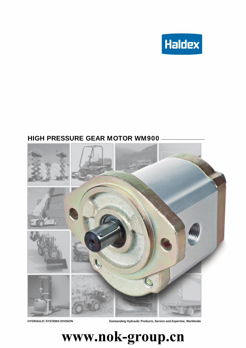
HIGH PRESSURE GEAR MOTOR WM900
HYDRAULIC SYSTEMS DIVISION Outstanding Hydraulic Products, Service and Expertise, Worldwide
www.nok-group.cn

THE POWER OF THE WM900 A SERIESHaldex Hydraulicss is one of the world’sleading manufacturers of hydraulic pumpsand motors. In recent years we havefocused on important markets, such asmaterials handling and vehicles, and nowthe result is in a series of high-performancehydraulic motors. The WM900 seriesbuilds on the versatile technical platformrepresented by the W series.
WM900 High Pressure Gear Motors areoptimised for demanding work, with harshweather conditions, rugged operationsand long service intervals. The WM900series is a range of cost-efficient group IImotors for all applications in which thecustomer’s demands for quality andreliability are particularly high.
Pictures on front page are used with the kind permission of eg: Atlet, BT, Huddig, Scania, Toro and Volvo Construction Equipment.The right to modifications for technical improvements is reserved.
WM900 DESCRIPTION & DATA 3
FLANGE CODE 03, 06, 07, 07-001M, 07-001V, 10 4 - 9
PORT SIZE SPECIFICATION 10 - 11
PERFORMANCE CURVES 12 - 13
DRAIN PORT & SHAFT CAPABILITY 14
INTEGRATED VALVE OPTIONS 15
HALDEX WM900 GB-03-03www.nok-group.cn

3
1
2
3
4
5
6
7
8
9
11
10
1 2 3 4 5 6 7 8 9 10 11
WM 09 A 1 C 080 R 03 BA 150 N
WM900 DESCRIPTIONThe WM900 motors are part of the W-family ofgear motors, which represent the mostadvanced motor design from Haldex Hydraulics.
The basic motor is of a three-piece modulardesign. The motor body is manufactured fromhigh strength aluminium alloy.
For optimum strength, gears and shafts areprecision machined as one piece. The 13-toothgear geometry has been optimised for lownoise level. The patented axial pressurecompensation ensures an excellent volumetricefficiency at all regular operating conditions(especially for motor applications in series).
Controlled internal oil flow results in con-tinuous lubrication and heat exchange. Thisenables operation across a wide speed rangeat very high loads. All shaft-bearing surfacesare Teflon® coated and sizes are calculated forlong service life. They also require low pressureto start the motor operation.
For applications with high radial loads and/or axial loads at the drive shaft motors areavailable with reinforced front bearings.
A wide range of mounting flanges and portsizes are available to meet European andinternational standards.
General DataDisplacement V 6 - 31 cc/revSpeed n 500 - 4000 rpmPressurerated pressure PI up to 276 barintermittent pressure PII up to 300 barpeak pressure PIII up to 330 barOperating temperatures t up to 105º CAverage volumetric efficiency 97 %
The maximum values for n, PI and t for a givenmotor specification may be applied simul-taneously dependent on selected motor andits specification.
PERFORMANCE DATA
p I
p II
p
Model code example for a single motor
= Type
= Series
= Design revision
= # of sections
= Seal material
= Displacement per section
= Rotation
= Mounting flange
= Drive shaft
= Portings
= Valve options
Operating pressure rangeThe motors will rotate also at differentialpressure ∆p<25 bar according to actualconditions. However, for specified motorperformance data a continuous differentialpressure of ∆p>25 bar is required from inlet tooutlet.
Maximum pressure at inlet port
Type Pressure (bar)Rated. p
IIntermitt. p
IIPeak p
III
WM09A1-060 276 300 330WM09A1-080 276 300 330WM09A1-110 276 300 330WM09A1-140 276 300 330WM09A1-160 276 300 330WM09A1-190 276 300 330WM09A1-230 221 245 265WM09A1-270 185 203 220WM09A1-310 170 185 200
Motors specified for only one direction (codesR or L) with internal drain cannot be loaded attheir outlet port by back pressures whichexceed the following limits:
P = 10.5 bar continuous,P = 17.0 bar short time.
If these pressure limits cannot be met you mustuse bi-directional motors (code B) with external
HALDEX WM900 GB-03-03
Options• SAE mounting flange, rectangular
flanges, through bolt model• Splined, tapered or straight shaft with key• Threaded or flanged ports• Reinforced front bearings• Built-in valves and specials• Fan drive motor
drain. For the external drain port the abovementioned back-pressure limits are still valid.Lead the drain line directly to the oil reservoir.Do not connect it to the return line with filtersbecause of possible back-pressure peaks.The bi-direction (code B) specified motors havean external drain port as standard, the abovementioned back-pressure limits are also valid forthese motors.Product has been tested to 1.000.000 cycles atpI. Intermittent pressure pII is permitted at max.20 sec loaded following 10 sec minimumunloaded.Product has been tested to 500.000 cycles at pIII.Above represents performance, which can beexpected from units incorporating flange portstyles.
Speed rangeMinimum speed for all motor sizes n = 500rpm at ∆p>25 bar.Maximum speed depends on both motor sizeand selected ports (see charts from page 4onwards).
Noise performanceData according to DIN 45 635.Typical levels at 200 bar and 2300 rpm usingmineral oil with viscosity of 40 mm2/s and at atemperature of 50º C:WM09A1-080 WM09A1-160 WM09A1-230
60 dB(A) 65 dB(A); 68 dB(A)
Hydraulic fluidsThe use of HL-or HLP-hydraulic oils accordingto DIN 51 524 is recommended.The permissible viscosity for all WM09 motorsranges from 750 to 10 mm2/s.The recommended operating viscosity range isfrom 40 to 16 mm2/s. The permissible cold startviscosity is 2000 mm2/s. We recommendcontacting Haldex Hydraulics before using fireresistant or bio-degradable fluids.
Temperature rangeAmbient temperature, min. -25° C
max. +80° CFluid temperature,
cont. operation, max. +90° Cshort term operation, max. +105° C
Please noteViscosity, when operating at above temperaturelimits, has to remain within the range specifiedunder ”Hydraulic Fluids”.
Fluid cleanlinessFluid cleanliness according to ISO 4406/1986Code 18/14 or better is required in order toassure the motor’s high level of efficiency over along period.
Power take offFlexible couplings are preferred for direct drives.For higher outboard side loads the motors areavailable with reinforced front bearing. See pages7 and 8 as well as page 14.
Mounting positionAs required.
SymbolsSingle motor uni-directionalSingle motor bi-directional
www.nok-group.cn

4
1 2 3 4 5 6 7 8 9 10 11
WM 09 A 1 C 080 R 03 BA 150 N
9
81
2
3
4
5
6
7
11
10
= Mounting flange03 SAE A 2-bolt
= Drive shaftBA SAE A key Ø 0,75“GA SAE A Spline11-tFA SAE A Spline 9-t
= Portingssee page 10, 11
= Valve options N – NoneOptions see page 15
= Type WM - Motor
= Series 09 - 900
= Design revision A
= # of sections 1 - Single2 - Duplex
= Seal material C - Buna/Viton
= Displacement per section(See Code Displ. below)
= RotationR - ClockwiseL - Counter clockwiseB - Bi-directional
FLANGE CODE 03 (SAE A 2 BOLT)
Size Differential pressure Torque Speed Flow, geom Dimensions Weightat ∆p=10 bar Max/min at n=1000 rpm A B (approx.)
Max ∆pI (bar) Mt (Nm) n [rpm] Q (litre/min) [mm] [mm] [kg]
060 - 6,0cc 276 0.905 4000/500 6 91.6 44.0 3,8080 - 8,0cc 276 1.16 4000/500 8 94.6 45.5 3,9110 - 11,0cc 276 1.6 3600/500 11 99.0 47.7 4,1
140 - 14,0cc 276 2.07 3500/500 14 103.5 50.0 4,2160 - 16,0cc 276 2.35 3300/500 16 106.4 51.4 4,3190 - 19,0cc 276 2.86 3300/500 19 110.9 53.7 4,4
230 - 23,0cc 221 3.36 3000/500 23 116.8 56.6 4,6270 - 27,0cc 185 4.05 2800/500 27 122.7 59.6 4,8310 - 31,0cc 170 4.41 2500/500 31 128.7 62.6 5,0
Model code example for a single motor
CLOCKWISE ROTATION
COUNTER CLOCKWISE ROTATION
INLET OUTLET
MOUNTING FLANGE 03
KEY 4.75x4.75x22.2
SHAFT BA
DRAIN PORT G 1/4 13 DEEPonly for bidirection code ’B’See page 14 for more details
EXTERNAL INVOLUTE SPLINE16/32 DP, 11 TEETH,FLAT ROOT SIDE FIT
SHAFT GA
EXTERNAL INVOLUTE SPLINE16/32 DP, 9 TEETH,FLAT ROOT SIDE FITMAX. TORQUE 87 NM
SHAFT FA
Minimum orderquantity 20 pcs
HALDEX WM900 GB-03-03
See page 14 for allowable external shaft load
www.nok-group.cn

5
1 2 3 4 5 6 7 8 9 10 11
WM 09 A 1 C 080 R 06 NB 160 N
1
2
3
4
5
6
7
8
9
10
11
= Mounting flange06 Rect. Ø 36,5 mm pilot
= Drive shaftNB European Tapered shaft 1:8
= Portingssee page 10, 11
= Valve options N – NoneOptions see page 15
FLANGE CODE 06FLANGE CODE 06 (RECTANGULAR - SMALL PILOT DIA)
Model code example for a single motor
Size Differential pressure Torque Speed Flow, geom Dimensions Weightat ∆p=10 bar Max/min at n=1000 rpm A B (approx.)
Max ∆pI (bar) Mt (Nm) n [rpm] Q (litre/min) [mm] [mm] [kg]
060 - 6,0cc 276 0.905 4000/500 6 91.6 44.0 3,8080 - 8,0cc 276 1.16 4000/500 8 94.6 45.5 3,9110 - 11,0cc 276 1.6 3600/500 11 99.0 47.7 4,1
140 - 14,0cc 276 2.07 3500/500 14 103.5 50.0 4,2160 - 16,0cc 276 2.35 3300/500 16 106.4 51.4 4,3190 - 19,0cc 276 2.86 3300/500 19 110.9 53.7 4,4
230 - 23,0cc 221 3.36 3000/500 23 116.8 56.6 4,6270 - 27,0cc 185 4.05 2800/500 27 122.7 59.6 4,8310 - 31,0cc 170 4.41 2500/500 31 128.7 62.6 5,0
CLOCKWISE ROTATION
COUNTER CLOCKWISE ROTATION
INLET OUTLET
MOUNTING FLANGE 06
DRAIN PORT G 1/4 13 DEEPonly for Bi-direction code ’B’See page 14 for more details
HEXA NUT M 12 x 1,5 TORQUE 50+10 NM
SHAFT NB
SPRING LOCK WASHER
KEY Nr. 405 (ANSI B17.2-1967)
TAPER 1:8
CODE 160Ports for unidirectional motors,
displacement 11-31 cc
CODE 159Ports for bidirectionalmotors, also valid forunidirectional motors,displacement 6-8cc
INLET OUTLET
HALDEX WM900 GB-03-03
= Type WM - Motor
= Series 09 - 900
= Design revision A
= # of sections 1 - Single2 - Duplex
= Seal material C - Buna/Viton
= Displacement per section(See Code Displ. below)
= RotationR - ClockwiseL - Counter clockwiseB - Bi-directional
M 6
13 DEEP
M 6
13 DEEP
M 8
13 DEEP
See page 14 for allowable external shaft load
www.nok-group.cn

6
1 2 3 4 5 6 7 8 9 10 11
WM 09 A 1 C 060 R 07 MB 150 N
7
6
5
4
3
2
1
11
10
9
8
FLANGE CODE 07 (RECTANGULAR - LARGE PILOT DIA)
Model code example for a single motor
Size Differential pressure Torque Speed Flow, geom Dimensions Weightat ∆p=10 bar Max/min at n=1000 rpm A B (approx.)
Max ∆pI (bar) Mt (Nm) n [rpm] Q (litre/min) [mm] [mm] [kg]
060 - 6,0cc 276 0.905 4000/500 6 91.6 44.0 3,8080 - 8,0cc 276 1.16 4000/500 8 94.6 45.5 3,9110 - 11,0cc 276 1.6 3600/500 11 99.0 47.7 4,1
140 - 14,0cc 276 2.07 3500/500 14 103.5 50.0 4,2160 - 16,0cc 276 2.35 3300/500 16 106.4 51.4 4,3190 - 19,0cc 276 2.86 3300/500 19 110.9 53.7 4,4
230 - 23,0cc 221 3.36 3000/500 23 116.8 56.6 4,6270 - 27,0cc 185 4.05 2800/500 27 122.7 59.6 4,8310 - 31,0cc 170 4.41 2500/500 31 128.7 62.6 5,0
CLOCKWISE ROTATION
COUNTER CLOCKWISE ROTATION
MOUNTING FLANGE 07
DRAIN PORT G 1/4 13 DEEPonly for Bi-direction code ’B’See page 14 for more details
HEXA NUT M 12 x 1,5, TORQUE 50+10 NM
SHAFT MB
SPRING LOCK WASHER
KEY 3 x 5 DIN 6888
EXTERNAL INVOLUTE SPLINEB17x14,DIN 5482, 9 TEETH,FLAT ROOT SIDE FIT
SHAFT JA
EXTERNAL INVOLUTE SPLINEW20x1.25x9g, DIN5480, 14 TEETH,FLAT ROOT SIDE FIT
SHAFT HA
TAPER 1:5MB
INLET OUTLET
See page 14 for allowable external shaft load
Minimum orderquantity 20 pcs
HALDEX WM900 GB-03-03
= Mounting flange07 Rect. Ø 80 mm pilot
= Drive shaftMB European Tapered shaft 1:5JA DIN 5482 Spline 9-tHA DIN 5480 Spline 14-t
= Portingssee page 10, 11
= Valve options N – NoneOptions see page 15
= Type WM - Motor
= Series 09 - 900
= Design revision A
= # of sections 1 - Single2 - Duplex
= Seal material C - Buna/Viton
= Displacement per section(See Code Displ. below)
= RotationR - ClockwiseL - Counter clockwiseB - Bi-directional
www.nok-group.cn

7
10 20 30 50 70 80 90 100 110 120 13040 600
0
15
45
90
105
135
120
75
30
60
daN
Xmm
1 2 3 4 5 6 7 8 9 10 11 12
WM 09 A 1 C 060 R 07 TB 150 N 001M
x
7
6
5
4
3
2
1
11
12
10
9
8
= Mounting flange07 Rect. Ø 80 mm pilot
= Drive shaftTB European Tapered shaft 1:5
= Portingssee page 10, 11
= Valve options N – NoneOptions see page 15
= Reinforced front bearing 001M
= Type WM - Motor
= Series 09 - 900
= Design revision A
= # of sections 1 - Single2 - Duplex
= Seal material C - Buna/Viton
= Displacement per section(See Code Displ. below)
= RotationR - ClockwiseL - Counter clockwiseB - Bi-directional
FLANGE CODE 07 MODEL WITH REINFORCEDFRONT BEARING, CODE 001M
Size Differential pressure Torque Speed Flow, geom Dimensions Weightat ∆p=10 bar Max/min at n=1000 rpm A B (approx.)
Max ∆pI (bar) Mt (Nm) n [rpm] Q (litre/min) [mm] [mm] [kg]
060 - 6,0cc 276 0.905 4000/500 6 123.1 75.5 3,8080 - 8,0cc 276 1.16 4000/500 8 126.1 77.0 3,9110 - 11,0cc 276 1.6 3600/500 11 130.5 79.2 4,1
140 - 14,0cc 276 2.07 3500/500 14 135.0 81.5 4,2160 - 16,0cc 276 2.35 3300/500 16 137.9 82,9 4,3190 - 19,0cc 276 2.86 3300/500 19 142.4 85.2 4,4
230 - 23,0cc 221 3.36 3000/500 23 148.3 88.1 4,6270 - 27,0cc 185 4.05 2800/500 27 154.2 91.1 4,8310 - 31,0cc 170 4.41 2500/500 31 160.2 94.1 5,0
Model code example for a single motor
CLOCKWISE ROTATION
COUNTER CLOCKWISE ROTATION
MOUNTING FLANGE 07
DRAIN PORT G 1/4 13 DEEPonly for Bi-direction code ’B’See page 14 for more details
HEXA NUT M 14 x 1,5 TORQUE 80+10 NM
SHAFT TB
SPRING LOCK WASHER
KEY 4 x 6,5 DIN 6888
TAPER 1:5TB
INLET OUTLET
Allowable radial load
w/o axial forcewith axial force of 100 daN
n = 1500 - 2000 rpmLH = 1000 - 2000 hours
HALDEX WM900 GB-03-03www.nok-group.cn

8
X10 20 30 50 70 80 90 100 110 120 13040 60
00
40
280
240
200
160
120
360
320
80
daN
mm
1 2 3 4 5 6 7 8 9 10 11 12
WM 09 A 1 C 060 R 07 TB 150 N 001V
x
7
6
5
4
3
2
1
11
10
9
8
12
= Mounting flange07 Rect. Ø 80 mm pilot
= Drive shaftTB European Tapered shaft 1:5
= Portingssee page 10, 11
= Valve options N – NoneOptions see page 15
= Reinforced front bearing 001V
= Type WM - Motor
= Series 09 - 900
= Design revision A
= # of sections 1 - Single2 - Duplex
= Seal material C - Buna/Viton
= Displacement per section(See Code Displ. below)
= RotationR - ClockwiseL - Counter clockwiseB - Bi-directional
FLANGE CODE 07 MODEL WITH REINFORCEDFRONT BEARING, CODE 001V
Model code example for a single motor
Size Differential pressure Torque Speed Flow, geom Dimensions Weightat ∆p=10 bar Max/min at n=1000 rpm A B (approx.)
Max ∆pI (bar) Mt (Nm) n [rpm] Q (litre/min) [mm] [mm] [kg]
060 - 6,0cc 276 0.905 4000/500 6 143,6 96,0 4,0080 - 8,0cc 276 1.16 4000/500 8 146,6 79,5 4,1110 - 11,0cc 276 1.6 3600/500 11 151,0 99,7 4,3
140 - 14,0cc 276 2.07 3500/500 14 155,5 102,0 4,4160 - 16,0cc 276 2.35 3300/500 16 158,4 103,4 4,5190 - 19,0cc 276 2.86 3300/500 19 162,9 105,7 4,6
230 - 23,0cc 221 3.36 3000/500 23 168,8 108,6 4,8270 - 27,0cc 185 4.05 2800/500 27 174,7 111,6 5,0310 - 31,0cc 170 4.41 2500/500 31 180,7 114,6 5,2
CLOCKWISE ROTATION
COUNTER CLOCKWISE ROTATION
MOUNTING FLANGE 07
DRAIN PORT G 1/4 13 DEEPonly for Bi-direction code ’B’See page 14 for more details
HEXA NUT M 14 x 1,5, TORQUE 80+10 NM
SPRING LOCK WASHER
KEY 4 x 6,5 DIN 6888
TAPER 1:5SHAFT TB
INLET OUTLET
Allowable radial load
w/o axial forcewith axial force of 130 daN
n = 1500 - 2000 rpmLH = 1000 - 2000 hours
HALDEX WM900 GB-03-03
SHAFT TB
www.nok-group.cn

1 2 3 4 5 6 7 8 9 10 11
WM 09 A 1 C 060 R 10 MB 150 N
9
7
6
5
4
3
2
1
11
10
9
8
= Mounting flange10 Through-bolt Ø 50 mm pilot
= Drive shaftMB European Tapered shaft 1:5JA DIN 5482 Spline 9-t
= Portingssee page 10, 11
= Valve options N – NoneOptions see page 15
= Type WM - Motor
= Series 09 - 900
= Design revision A
= # of sections 1 - Single2 - Duplex
= Seal material C - Buna/Viton
= Displacement per section(See Code Displ. below)
= RotationR - ClockwiseL - Counter clockwiseB - Bi-directional
FLANGE CODE 10 THROUGH - BOLT
Model code example for a single motor
Size Differential pressure Torque Speed Flow, geom Dimensions Weightat ∆p=10 bar Max/min at n=1000 rpm A B (approx.)
Max ∆pI (bar) Mt (Nm) n [rpm] Q (litre/min) [mm] [mm] [kg]
060 - 6,0cc 276 0.905 4000/500 6 89,1 41,5 3,6080 - 8,0cc 276 1.16 4000/500 8 92,1 43,0 3,7110 - 11,0cc 276 1.6 3600/500 11 96,5 45,2 3,9
140 - 14,0cc 276 2.07 3500/500 14 101,0 47,5 4,2160 - 16,0cc 276 2.35 3300/500 16 103,9 48,9 4,3190 - 19,0cc 276 2.86 3300/500 19 108,4 51,2 4,4
230 - 23,0cc 221 3.36 3000/500 23 114,3 54,1 4,6270 - 27,0cc 185 4.05 2800/500 27 120,2 57,1 4,8310 - 31,0cc 170 4.41 2500/500 31 126,2 60,1 5,0
CLOCKWISE ROTATION
COUNTER CLOCKWISE ROTATION
MOUNTING FLANGE 10
DRAIN PORT G 1/4 13 DEEPonly for Bi - direction code ’B’See page 14 for more details
HEXA NUT M 12 x 1,5, TORQUE 50+10 NM
SHAFT MB
SPRING LOCK WASHER
KEY 3 x 5 DIN 6888
TAPER 1:5
INLET OUTLET
2x BOLT M 10-10.9, TORQUE 56+4 Nm
(not included)
EXTERNAL INVOLUTE SPLINEB17x14, DIN 5482, 9 TEETH,FLAT ROOT SIDE FIT
SHAFT JA
See page 14 for allowable external shaft load
Minimum orderquantity 20 pcs
HALDEX WM900 GB-03-03www.nok-group.cn
10
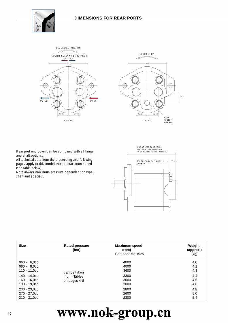
Size Rated pressure Maximum speed Weight(bar) (rpm) (approx.)
Port code 521/525 [kg]
060 - 6,0cc 4000 4,0080 - 8,0cc 4000 4,1110 - 11,0cc 3600 4,3
140 - 14,0cc 3300 4,4160 - 16,0cc 3000 4,5190 - 19,0cc 3000 4,6
230 - 23,0cc 2800 4,8270 - 27,0cc 2600 5,0310 - 31,0cc 2300 5,4
DIMENSIONS FOR REAR PORTS
Rear port end cover can be combined with all flangeand shaft options.All technical data from the preceeding and followingpages apply to this model, except maximum speed(see table below).Note always maximum pressure dependent on type,shaft and specials.
CLOCKWISE ROTATION
COUNTER CLOCKWISE ROTATION
INLETOUTLET
BI-DIRECTION
G 1/413 DEEPDrain Port
USE OF REAR PORT COVERWILL INCREASE DIMENSION’A’ BY 10.2 MM FOR ALL MOTORS
FOR THROUGH BOLT MODELSCODE 10
CODE 521 CODE 525
HALDEX WM900 GB-03-03
can be takenfrom Tableson pages 4-8
www.nok-group.cn
11
03
03
07
10
03
06
07
10
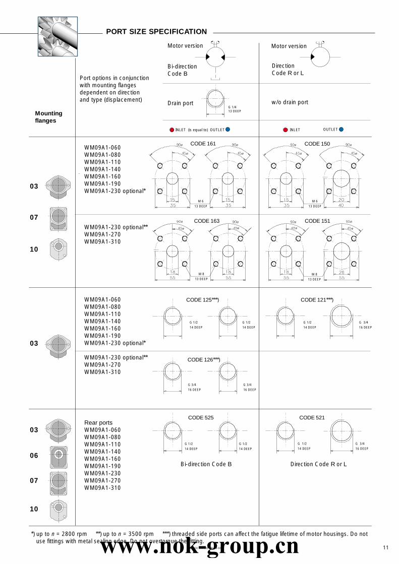
PORT SIZE SPECIFICATION
Mountingflanges
WM09A1-060WM09A1-080WM09A1-110WM09A1-140WM09A1-160WM09A1-190WM09A1-230 optional*
WM09A1-230 optional**WM09A1-270WM09A1-310
WM09A1-060WM09A1-080WM09A1-110WM09A1-140WM09A1-160WM09A1-190WM09A1-230 optional*
WM09A1-230 optional**WM09A1-270WM09A1-310
Rear portsWM09A1-060WM09A1-080WM09A1-110WM09A1-140WM09A1-160WM09A1-190WM09A1-230WM09A1-270WM09A1-310
Bi-direction Code B Direction Code R or L
Port options in conjunctionwith mounting flangesdependent on directionand type (displacement)
Bi-directionCode B
DirectionCode R or L
w/o drain portG 1/413 DEEP
CODE 161
INLET OUTLETINLET (is equal to) OUTLET
CODE 150
M 6
13 DEEP
M 6
13 DEEP
CODE 163 CODE 151
M 8
13 DEEPM 8
13 DEEP
CODE 125***) CODE 121***)
G 1/2
14 DEEP
G 1/2
14 DEEP
G 1/2
14 DEEP
G 3/4
16 DEEP
CODE 126***)
G 3/4
16 DEEP
G 3/4
16 DEEP
CODE 525 CODE 521
G 1/2
14 DEEP
G 1/2
14 DEEP
G 3/4
16 DEEPG 1/2
14 DEEP
Motor version Motor version
Drain port
*) up to n = 2800 rpm **) up to n = 3500 rpm ***) threaded side ports can affect the fatigue lifetime of motor housings. Do not use fittings with metal sealing edge. Do not overtorque the fitting.
HALDEX WM900 GB-03-03www.nok-group.cn
12
0 500 1000 1500 2500 35002000 3000 40000
10
15
20
5
p =276 bar
Q =
4 L
/min
Q =
6 L
/min
Q =
8,3
L/m
in
Q =
9 L
/min
Q =
18
L/m
in
Q =
18
L/m
inQ
= 1
4 L/
min
Q =
12
L/m
inQ
= 1
6 L/
min Q =
22
L/m
in
Q =
24
L/m
in
Q =
24
L/m
in
Q =
32
L/m
in
Q =
32
L/m
in
Q =
40
L/m
in
p =200 bar
p =140 bar
p =70 barp =35 bar
p =276 bar
p =200 bar
p =140 bar
p =70 bar
p =35 bar
p = 9kW
p = 7kW
p = 5kW
p = 3kW
p = 1kW
500 1000 1500 2500 35002000 30000
0
10
15
25
35
45
20
30
40
5
0 500 1000 1500 2500 35002000 3000 40000
10
15
20
25
30
5
p =276 bar
p =200 bar
p =140 bar
p =70 bar
p =35 bar
p = 9kW
p = 11kW
p = 7kW
p = 5kW
p = 3kW
p = 1kW
p = 4kW
p = 8kW
p = 12kW
p = 16kW
p = 1kW
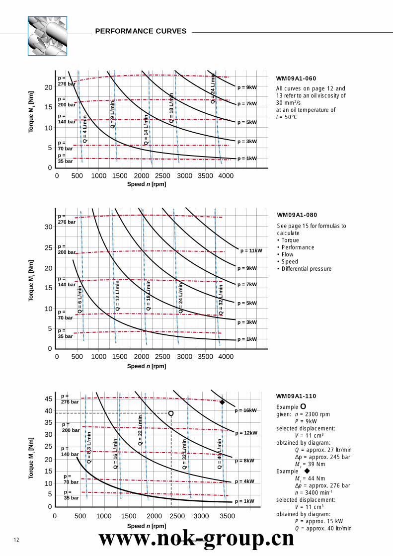
All curves on page 12 and13 refer to an oil viscosity of30 mm2/sat an oil temperature oft = 50°C
See page 15 for formulas tocalculate• Torque• Performance• Flow• Speed• Differential pressure
Example Ogiven: n = 2300 rpm
P = 9kWselected displacement:
V = 11 cm3
obtained by diagram:Q = approx. 27 ltr/min∆p = approx. 245 barMt = 39 Nm
ExampleMt = 44 Nm∆p = approx. 276 barn = 3400 min-1
selected displacement:V = 11 cm3
obtained by diagram:P = approx. 15 kWQ = approx. 40 ltr/min
Torq
ue M
t [N
m]
Speed n [rpm]
Torq
ue M
t [N
m]
Torq
ue M
t [N
m]
WM09A1-060
WM09A1-080
WM09A1-110
PERFORMANCE CURVES
HALDEX WM900 GB-03-03
Speed n [rpm]
Speed n [rpm]
www.nok-group.cn

13
500 1000 1500 2500 35002000 30000
0
10
15
25
35
45
55
20
30
40
50
60
5
p =276 bar
Q =
9,5
L/m
in
Q =
20
L/m
in
Q =
20
L/m
in
Q =
30
L/m
in
Q =
42
L/m
in
Q =
54
L/m
in
Q =
10
L/m
in
Q =
32
L/m
in
Q =
40
L/m
in
Q =
13
L/m
inQ
= 1
6 L/
min
Q =
28
L/m
in
Q =
57
L/m
in
Q =
75,
5 L/
min
Q =
76
L/m
in
Q =
17,
5 L/
min
Q =
42
L/m
in
Q =
32
L/m
in
Q =
50
L/m
in
Q =
60
L/m
in
Q =
12,
9 L/
min
Q =
24
L/m
in
Q =
25
L/m
in
Q =
35
L/m
in
Q =
55
L/m
in
Q =
68
L/m
in
Q =
36
L/m
in
Q =
50
L/m
in
Q =
63
L/m
inQ
= 5
0 L/
min
p =200 bar
p =140 bar
p =70 barp =35 bar
p = 4kW
p = 8kW
p = 12kW
p = 16kW
p = 20kW
p = 1kW
500 1000 1500 2500 35002000 30000
0
10
15
25
35
45
55
20
30
40
50
60
6570
5
p =276 bar
p =200 bar
p =140 bar
p =70 barp =35 bar
p = 4kW
p = 8kW
p = 12kW
p = 16kW
p = 20kW
p = 22kW
p = 1kW
500 1000 1500 2500 35002000 30000
0
10
15
25
35
45
55
20
30
40
50
6065
70
75
80
5
p =276 bar
p =200 bar
p =140 bar
p =70 bar
p =35 bar
p = 4kW
p = 8kW
p = 12kW
p = 16kW
p = 20kW
p = 24kW
p = 1kW
500 1000 1500 250020000
0
10
15
25
35
45
55
20
30
40
50
60
65
70
75
80
5
p =165 bar
p =125 bar
p =80 bar
p =40 bar
p =20 bar
p = 4kW
p = 8kW
p = 12kW
p = 16kW
p = 20kW
500 1000 1500 25002000 30000
0
10
15
25
35
45
55
20
30
40
50
60
65
75
70
5
p =160 bar
p =221 bar
p =100 bar
p =50 bar
p =25 bar
p = 4kW
p = 8kW
p = 12kW
p = 16kW
p = 20kW
p = 1kW
500 1000 1500 25002000 30000
0
10
15
25
35
45
55
20
30
40
50
60
65
75
70
5
p =150 bar
p =186 bar
p =100 bar
p =50 bar
p =25 bar
p = 4kW
p = 8kW
p = 12kW
p = 16kW
p = 20kW
p = 1kW
Torq
ue M
t [N
m]
Speed n [rpm]
Torq
ue M
t [N
m]
Speed n [rpm]
Speed n [rpm]
Torq
ue M
t [N
m]
Speed n [rpm]
Torq
ue M
t [N
m]
Speed n [rpm] Speed n [rpm]
WM09A1-140 WM09A1-160
WM09A1-190 WM09A1-230
WM09A1-270 WM09A1-310
HALDEX WM900 GB-03-03
Torq
ue M
t [N
m]
Torq
ue M
t [N
m]
www.nok-group.cn

14
285°
255°
225°
195°165°150°
120°
90°
135°
105°
75°
60°
45°
15°30°
240°
210°
180°
315°
345°0°
300°
270°
330°
Ps1
Ps2
Ps1
Ps2 Ps2
1400 N
1200 N
1000 N
800 N
600 N
400 N 75°
105°
135°
165°195°210°
240°
270°
225°
255°
285°
300°
315°
345°330°
120°
150°
180°
45°
15°0°
60°
90°
30°1400 N
1200 N
1000 N
800 N
600 N
400 N
DRAIN PORT POSITIONS FOR LATERAL INLET AND OUTLET
Size Curve PS1 Curve PS2< ∆p (bar) > ∆p (bar)
060 - 6,0cc 276 -080 - 8,0cc 276 -110 - 11,0cc 276 -140 - 14,0cc 200 200160 - 16,0cc 200 200190 - 19,0cc 160 160
230 - 23,0cc 160 160270 - 27,0cc 125 125310 - 31,0cc 100 100
ALLOWABLE RADIAL LOAD AND AXIAL LOAD AT DRIVE SHAFT(W/O REINFORCED FRONT BEARING)
Allowable radial load PS dependent on direction of forcerelated to motor for counter clockwise rotation, code L.
Allowable radial load PS dependent on direction of forcerelated to motor for clockwise rotation, code R.
Maximum allowable axialforce for both directionsPT = 700 Nat viscosity of 10 cSt.
Sum of PT + PS does notexceed 1050 N if appearsimultaneously.
Radial pre-load used at V-beltdrive is not permissable forfluid motors w/o reinforcedfront bearing.
Flange fixing/Flange surface
G 1/413 DEEP
Drain port
Driveshaftcentre
OptionalLateral drain portG 1/4, 13 DEEP
Position ”LH”Code 026Special
Position ”RH”Code 025Special
PS
PT
Drain port Standard positionBi-direction code B
Option ”Lateral drain port”Alternative position ”RH” or ”LH”
Bi-direction code B
HALDEX WM900 GB-03-03www.nok-group.cn

15
MOTORS WITH BUILT-IN VALVE FEATURESFOR SPECIAL APPLICATIONS (options)
Formulas for calculating data of hydraulic motors
Hydraulic motorfor one directiononly with built-inanti-cavitationvalve.
Hydraulic motor forone direction onlywith built-in anti-cavitation valve.Second directionwith bypass-throttle.
Hydraulic motor for one direction with built-in, non-adjustable pressure relief valve (left)and additional anti-cavitation valve (right).Both types are not released for serial circuits.
Solid motor-pump-unit for circuits forlubricant orcoolant, if otherpump drives aretoo sophisticated.Hydraulic fluidhermetically sepa-rated from others.
Torque Mteff [Nm]
Mteff =1,59 • V [cm3] • ∆p [bar] • mech
100
Flow Qeff [litre/min]
Qeff =V [cm3] • n [rpm]
V [cm3] = geometric displacement, see charts
volumetric• 1000
Performance P [kW]
P =Q [litre/min] • ∆p [bar] • total
612
HALDEX WM900 GB-03-03
P
P Mot. T Mot.
HD
55°CT
T
Hydraulic motor with thermocontrolled bypassvalve, pressurerelief valve and anti-cavitationvalve.
Hydraulic motor for one direction withinternal proportional pressure relief valveand optional anti-cavitation valve.
www.nok-group.cn