high-precision atomic physics calculations using parallel processing … · 2002-06-01 · ii this...
TRANSCRIPT

High-Precision Atomic Physics Calculations Using Parallel Processing in a Distributed Environment: Application to Quantum Computer Development
By
George F. Willard III
A REPORT
Submitted in partial fulfillment of the requirements
for the degree of
MASTER OF SCIENCE IN COMPUTER SCIENCE
MICHIGAN TECHNOLOGICAL UNIVERSITY
2001

ii
This report, “High-Precision Atomic Physics Calculations Using Parallel Processing in a Distributed Environment: Application to Quantum Computer Development”, is hereby approved in partial fulfillment of the requirements for the Degree of MASTER OF SCIENCE IN COMPUTER SCIENCE.
DEPARTMENT of Computer Science
Signatures:
Report Advisor Dr. Jean Mayo
Department Chair Dr. Linda Ott
Date

iii
ADVISOR
Dr. Jean Mayo
Assistant Professor
Computer Science
COMMITTEE
Dr. Linda Ott
Department Chair and Professor
Computer Science
Dr. Adrian Sandu
Assistant Professor
Computer Science
Dr. Warren F. Perger
Associate Professor
Electrical and Computer Engineering

iv
Acknowledgements I would like to express my sincere gratitude to Dr. Warren F. Perger for his encouragement, enthusiasm, and outstanding assistance making my involvement in this project possible as both a Masters project and Internet 2 project for the Information Technology Department of Michigan Technological University. I am grateful to Dr. Jean Mayo for understanding my position as a professional staff member of the Distributed Computing Services division of Information Technology pursuing a graduate degree, and for making it as painless as possible to be both a full time staff member and graduate student. The Information Technology Department of Michigan Technological University continues to be very supportive of this project, and provides the campus network infrastructure and Internet 2 connection that makes high-speed inter-institutional distribution of computation possible for this project. I also thank Ann West, Director of Distributed Computing services, for her assistance and resources in making this project possible. I look forward to continuing my work with Warren and my committee on this very exciting project, and I thank Dr. Linda Ott and Dr. Adrian Sandu for their continual feedback, time, and support.

v
Abstract
The demand for faster and smaller computer components is driving exploration beyond the scope of conventional fabrication techniques, and into atomic scale models where classical physics breaks down. By understanding and simulating the quantum level interaction of atoms, the atom is no longer a size limit, and immensely powerful quantum computers can be created. Experimentation on an atomic scale is extremely cost prohibitive, but can be simulated on a computer. Accurate computer simulation of the interactions among atoms and the changes in atomic energy values is, however, extremely computationally intensive. An integrated program for the ab initio calculation of atomic characteristics using many-body perturbation theory (MBPT), ISNAP, was created to calculate atomic energy levels resulting in error-free expressions for an order-by-order calculation. These expressions require several days or weeks to evaluate certain terms, and the current program has limited simulation capabilities. The existing code base has been refactored in order to offer additional simulation capabilities, handle more complex simulations, and simultaneously utilize multiple computers. A distributed agent system with a message passing intercommunication mechanism was developed to break up the calculations and load balance the computations across multiple computers. A specialized equation fragment solver is implemented to allow for a single method of computing multiple orders. The introduction of multithreaded processing and a radial function caching mechanism significantly reduces the execution time for the computations. The created Distributed Calculation of Atomic Characteristics (DCAC) distribution consists of a set of agent programs, configuration files, corresponding source code, and sufficient documentation to configure the hierarchical distributed system and execute atomic energy level simulations in distributed processing environments.

vi
Contents
1 Introduction 1 2 Related Work 1
2.1 Faster and Smaller...............................................................................................1 2.2 Classical and Quantum Mechanics .....................................................................1 2.3 Towards Quantum Computing............................................................................2 2.4 Distributed Processing ........................................................................................2 2.5 Many Body Perturbation Theory ........................................................................3 2.6 An Integrated Approach......................................................................................3
3 Refactoring the Code Base 4
3.1 Code Execution Profiling....................................................................................4 3.2 Narrowing of Variable Scope .............................................................................5 3.3 File Naming and Organization ...........................................................................5 3.4 Result Verification and Corectness ....................................................................6 3.5 Removal of Unnecessary Subroutines ................................................................6 3.6 Porting the FORTRAN Computational Subroutines to C...................................7
4 Dismantiling the Equations 7
4.1 Removal of Artificial Dependencies...................................................................8 4.2 The coeff_eval Function......................................................................................8 4.3 Block Model........................................................................................................9 4.3.1 Master Block Structure .............................................................................9 4.3.2 Block Strucutre .......................................................................................10 4.3.3 Block File Serialization...........................................................................11
5 Distributed Processing Model 11
5.1 Server Agent .....................................................................................................12 5.2 Proxy Agent ......................................................................................................13 5.3 Subagent State Management .............................................................................13 5.4 Server and Proxy Agent Scoreboard .................................................................14 5.5 Client Agent ......................................................................................................14 5.6 Example Distributed Topology.........................................................................14 5.7 Client Level Parallelism....................................................................................15
6 Multithreading 16
6.1 POSIX Threads .................................................................................................16 6.2 Threaded Server and Proxy Agents ..................................................................16 6.3 Client Level Thread Usage ...............................................................................16 6.4 Client Agent Parallelism...................................................................................17
7 Distributed Agent Design 17
7.1 GNU Autoconf and Automake .........................................................................17 7.2 The Design of the Agent Core ..........................................................................18

vii
7.3 Server Agent Design .........................................................................................19 7.4 Proxy Agent Design ..........................................................................................19 7.5 Client Agent Design..........................................................................................20 7.6 Standalone Processor Design ............................................................................20 7.7 Objectives and Requirements............................................................................20 7.7.1 Support for Large Network Environments .............................................20 7.7.2 Accommodate Varying Levels of Network Connectivity ......................21 7.7.3 Evolution of the Code Base ....................................................................21 7.7.4 Make the Program More General Purpose..............................................21 7.7.5 High Portability.......................................................................................22 7.7.6 Maintainability........................................................................................22
8 Agent Intercommunication 22
8.1 Server Agent Intercommunication....................................................................22 8.2 Proxy Agent Intercommunication.....................................................................22 8.3 Client Agent Intercommunication.....................................................................23 8.4 Agent Control Program.....................................................................................23 8.5 Platform Independent Messaging .....................................................................24 8.6 Agent Control Messages ...................................................................................25 8.7 Hostname Based Connection Restrictions ........................................................26 8.8 Secure Tunneling ..............................................................................................26 8.8.1 Secure Shell Tunneling ...........................................................................27 8.8.2 Secure Socket Layer Tunneling ..............................................................27
9 Radial Cache 28
9.1 Open Hash Table Design ..................................................................................28 9.1.1 Hash Table Key Generation....................................................................30 9.2 Configuration and Limitations ..........................................................................30 9.3 Radial Cache Usage Analysis ...........................................................................31 9.4 Tuning the Radial Cache...................................................................................32
10 Block Processing and Management 33
10.1 Standalone Processing ....................................................................................33 10.2 Block File Management ..................................................................................33
11 Cluster Environments 34
11.1 Beowulf Clusters.............................................................................................34
12 Conclusions and Future Work 35
Appendix A Distributed Calculation of Atomic Characteristics 37 A.1 Obtaining the Source Distribution ...................................................................37 A.2 Building the DCAC Distribution .....................................................................37 A.3 Installing the DCAC Tools ..............................................................................38 A.4 Configuring the Agents ....................................................................................38 A.4.1 Configuration File Parameters ...............................................................39

viii
A.5 Jobfile and Trials Directory .............................................................................42 A.6 Running the Distrbuted Agents ........................................................................43 A.7 Controlling the Distrbuted Agents ...................................................................43 A.8 Reporting Results .............................................................................................45 A.9 Setting Block and Basis File Labels ................................................................46 A.10 Generating Block Files for the Standalone Processor....................................47 A.11 Using the Standalone Processor.....................................................................49 A.12 Merging Block Files.......................................................................................49 A.13 Debugging and Troubleshooting....................................................................50 A.13.1 Stadalone Mode Debugging.................................................................50 A.13.2 Agent Mode Debugging.......................................................................51
Appendix B DCAC Distribution and Source Code Files 52
B.1 DCAC Binary Distribution Files ......................................................................52 B.2 DCAC Source Code Files ................................................................................53
Appendix C Test Host Configurations 58

ix
List of Figures
1 Integrated Program for Calculation of Atomic Characterstics ............................4 2 Example Equation Fragment Evaluated by coeff_eval........................................9 3 Master Block Structure ......................................................................................10 4 Block Structure ..................................................................................................11 5 Processing Models .............................................................................................12 6 Example Sub-Agent Status Table ......................................................................14 7 Example Scoreboard Entries ..............................................................................14 8 Example Hierarchical Model .............................................................................15 9 Block Distribution Diagram...............................................................................15 10 Example Message Passing .................................................................................24 11 Agent Control Messages ....................................................................................26 12 Example Tunneling Configuration ....................................................................27 13 Radial Cache Structure.......................................................................................29 14 Radial Cache Key Components .........................................................................30 15 Example Radial Cache Statistics Lines..............................................................31 16 Radial Cache Effect on Block Completion Time ..............................................32 17 Example hostlist Entries ....................................................................................34 18 Collective Script Syntax ....................................................................................34 19 Example Beowulf Agent Configuration ............................................................35 20 Building the DCAC Distribution .......................................................................38 21 Installing the DCAC Distribution......................................................................38 22 Example jobfile Entries......................................................................................42 23 dcac_control Example........................................................................................44 24 dcac_control Command Line Options ...............................................................44 25 dcac_control Program Command Set ................................................................45 26 Basic dcac_report Usage ....................................................................................45 27 dcac_report Range Specification and Summary Display...................................46 28 dcac_label Example Usage ................................................................................47 29 Block Generation Example ................................................................................48 30 Block Result Testing with the dcac_process Utility..........................................49 31 dcac_block_merge Example ..............................................................................50 32 DCAC Binary Distribution Files .......................................................................53 33 DCAC Source Code Distribution Files ..............................................................57 34 IBM PC Compatible Test Linux Configuration.................................................58 35 Dual Processor IBM PC Compatible Linux Test Configuration.......................58 36 Sun Microsystems Test Solaris Workstation Configuration..............................58 37 Sun Microsystems Test Solaris Server Configuration.......................................58 38 SGI Test Irix Configuration...............................................................................59 39 Beowulf Cluster Test Configuration..................................................................59

1
1 Introduction The demand for faster computers and higher data storage capacity continues to rise as the size of the components is expected to be reduced or stay the same. These expectations are encouraging the exploration of miniaturization of existing component fabrication techniques and alternatives to current design techniques. The smallest possible physical component that can be used for storage or information passing is the atom. At an atomic level, however, classical physics breaks down and the behavior of the atomic energy levels is better modeled by utilizing the quantum effects to represent information or states of information. Physical experimentation and measurement of atomic energy levels is extremely cost prohibitive, but the mathematical models used in computational chemistry allow for computer simulation of atomic properties. Accurate computer simulation of the interactions among atoms and the changes in atomic energy values is extremely computationally intensive. Simulation programs have been constructed that have demonstrated accurate computation and modeling of different aspects of the atomic characteristics, and integrated [15] to provide a complete approach to calculating atomic characteristics. The computational time required to execute a complete simulation of the integrated program is very large. In order to address this, the existing code base of the integrated program has been refactored into a distributed processing model. The new model as described herein allows multiple computers to participate in the calculations in parallel thus producing simulation results in significantly less time utilizing dedicated processing hosts, and additional computational cycles provided by client agents processing on participating host computers and workstations. The reduced time for a complete simulation will allow researchers to experiment with more complex interactions and configurations in a time effective manner. 2 Related Work 2.1 Faster and Smaller Moore's Law states that computer chip feature size decreases exponentially with time [13]. The computer chip and microprocessor industry has been steadily following Moore's Law, suggesting that atomically precise computers will debut by about 2010-2015. The ability to represent additional states, beyond the traditional binary on/off, with a given construct also exponentially expands the amount of data that the construct can hold. To achieve smaller components and extend the number of states that can be represented, new techniques and approaches will be developed that are not necessarily a miniaturization of existing techniques. 2.2 Classical and Quantum Mechanics At an atomic level classical physics breaks down and the behavior of the atomic energy levels is better modeled by utilizing the quantum effects to represent information or states

2
of information. This will require a great deal of measurement, calculations, quantum theory application, and verification mechanisms to determine the quantum state of atoms. Molecular and atomic level manipulation will also be necessary to build nanotechnology and quantum structures. NASA has been pursuing the creation and use of carbon nanotubes to engrave features on silicon surfaces that are of nanometer scale [9]. Exploration into the interaction directly of nanotubes and other nano-structures, bypassing the silicon wafers, is also being investigated [8]. Understanding the atomic energy levels, material properties, and modeling of these systems will require a solid understanding of the atomic interactions and quantum effects. 2.3 Towards Quantum Computing Research in developing the quantum equivalent of classical components appears to be accelerating as fast as the technology that will be required to manufacture the components. Quantum bits, or qubits, rely upon the quantum state of an atom, but due to the principle of superposition, a quantum system can be in all possible states simultaneously. To help reduce the possible number of states, a quantum dot, a tiny finger of aluminum deposited on an insulating layer on a chip, can be used to reduce the states to the classical 0 and 1 [14], but limits the amount of information that could have been stored in the same atoms and computed with quantum equations. Storage of information on the atomic level is useless without the addition of the transistor and logic gates needed to control the data and build the circuit foundation of a quantum computer. Logic gates on a quantum level must also be constructed to handle the quantum effects of atoms and be fault-tolerant in order to be reliably used to construct circuits. These logic gates need to be self-testing, and knowledge of the quantum energy state manipulation is crucial in the construction of the gates [6]. Quantum computers will be able to solve certain computational problems significantly faster than on classical computers [16]. By examining the advantages and multiple state capability, and rethinking traditional algorithms, quantum computers can be applied to problems that are otherwise unsolvable. Modern data encryption schemes require the factoring of large prime numbers, a task that can be super-accelerated on a quantum computer, thus future generations of encryption technology will have to be more sophisticated, even quantum computer based to protect data [2]. 2.4 Distributed Processing It is common for computational models that require large amounts of processing to be designed such that a supercomputer can provide the required back-end processing and a workstation the front-end user interface. Implementation of this approach is significantly less difficult than a fully distributed model, but does not scale sufficiently to handle larger computational problems. A distributed model can provide the additional flexibility and computational power to drive very complex computations in parallel, operating

3
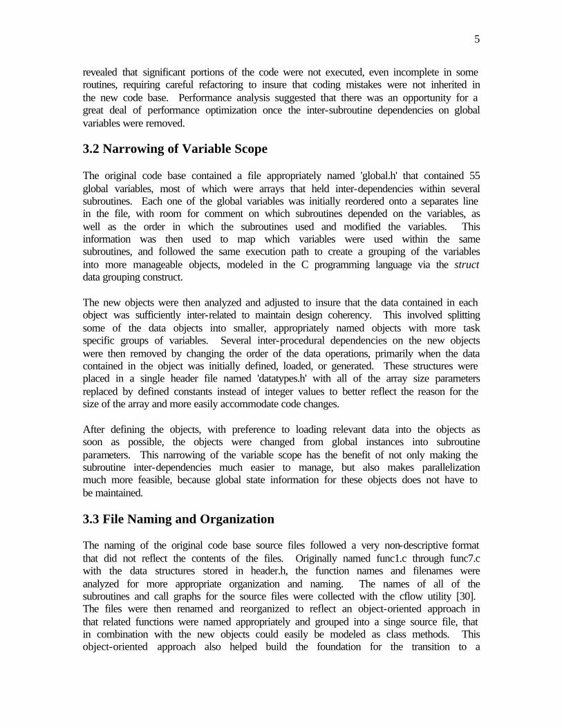
logically as a single entity. This approach has been taken in various simulation environments including molecular visualization and virtual reality applications [3]. With the growth of the Internet, and advent of Internet 2, it is very feasible to distribute processing to remote networks and computers to handle very large computational problems. The distributed.net team designed a distributed processing system to brute force crack encryption mechanisms, and their overall "computing power has grown to become equivalent to that of more than 160,000 PII 266MHz computers working 24 hours a day, 7 days a week, 365 days a year" [20]. Other projects have successfully taken advantage of spare computing cycles and distributed processing with widespread participation by the Internet community. [27] 2.5 Many Body Perturbation Theory Many body perturbation theory (MBPT) techniques can be used to effectively calculate atomic properties, including the energy levels needed to build quantum components. The calculations exhibit the gradually increasing precision needed to model on an atomic scale, yielding results that can be experimentally verified. The necessary calculations are computationally intensive, and programs have been constructed that can correctly calculate atomic properties [15]. 2.6 An Integrated Approach An integrated program for calculation of atomic characteristics using MBPT was created by Dr. Warren F. Perger [15], and the calculation portion translated to C code by Yogesh Andra, to calculate atomic energy levels using many body perturbation theory techniques [1]. Figure 1 represents the different stages of this approach, with the portions that will be converted into a distributed system highlighted. Although the execution time of the MBPT calculations was significantly reduced after the conversion to C code, the code base was unpolished and inefficient. Andra proposed the extension of the code base into a polished product that executed in parallel efficiently, and supported automatic configuration for platform specific features as future work. The proposed coarse-grained parallelization the program by executing the different order terms of the equations in parallel does not scale beyond two processors in his original C code base. This approach also does not balance the load of solving the MBPT equation fragments. A fine-grained parallelization method is needed to extend the existing code base to handle efficient scalable parallel execution of the different orders of the MBPT equations.

4
Figure 1: Integrated Program for Calculation of Atomic Characterstics The code base has been refactored into a distributed processing system in order to offer additional simulation capabilities, handle more complex simulations, and simultaneously utilize multiple computers to reduce the execution time. 3 Refactoring the Code Base The code base for the integrated program for calculation of atomic characteristics using MBPT [1] exhibited many characteristics that made it a difficult starting point for constructing a distributed solution. This code base has been completely redesigned with the primary goals of supporting parallel and distributed execution of the program, and reducing the execution time of the core components. The combination of a distributed model, program execution analysis, and strategic refactoring was able to achieve these goals. 3.1 Code Execution Profiling In order to optimize the new code base for parallel execution, the execution characteristics of the original non-parallel version were analyzed. Coverage analysis
Atomic Configuration Data: Particles, MBPT order
Create MBPT terms in Mathematica
Kentaro: Performs Angular Reduction
Calculation of Atomic Properties
Calculate RL(abcd)
Calculate relativistic
atomic orbitals
5
revealed that significant portions of the code were not executed, even incomplete in some routines, requiring careful refactoring to insure that coding mistakes were not inherited in the new code base. Performance analysis suggested that there was an opportunity for a great deal of performance optimization once the inter-subroutine dependencies on global variables were removed. 3.2 Narrowing of Variable Scope The original code base contained a file appropriately named 'global.h' that contained 55 global variables, most of which were arrays that held inter-dependencies within several subroutines. Each one of the global variables was initially reordered onto a separates line in the file, with room for comment on which subroutines depended on the variables, as well as the order in which the subroutines used and modified the variables. This information was then used to map which variables were used within the same subroutines, and followed the same execution path to create a grouping of the variables into more manageable objects, modeled in the C programming language via the struct data grouping construct. The new objects were then analyzed and adjusted to insure that the data contained in each object was sufficiently inter-related to maintain design coherency. This involved splitting some of the data objects into smaller, appropriately named objects with more task specific groups of variables. Several inter-procedural dependencies on the new objects were then removed by changing the order of the data operations, primarily when the data contained in the object was initially defined, loaded, or generated. These structures were placed in a single header file named 'datatypes.h' with all of the array size parameters replaced by defined constants instead of integer values to better reflect the reason for the size of the array and more easily accommodate code changes. After defining the objects, with preference to loading relevant data into the objects as soon as possible, the objects were changed from global instances into subroutine parameters. This narrowing of the variable scope has the benefit of not only making the subroutine inter-dependencies much easier to manage, but also makes parallelization much more feasible, because global state information for these objects does not have to be maintained. 3.3 File Naming and Organization The naming of the original code base source files followed a very non-descriptive format that did not reflect the contents of the files. Originally named func1.c through func7.c with the data structures stored in header.h, the function names and filenames were analyzed for more appropriate organization and naming. The names of all of the subroutines and call graphs for the source files were collected with the cflow utility [30]. The files were then renamed and reorganized to reflect an object-oriented approach in that related functions were named appropriately and grouped into a singe source file, that in combination with the new objects could easily be modeled as class methods. This object-oriented approach also helped build the foundation for the transition to a

6
distributed model where objects and messages would then be exchanged in a multiprocessor and networked environment. 3.4 Result Verification and Correctness The most time consuming portion of the entire refactoring process was the verification that the incremental modifications to the code base did not change or corrupt the calculation results. Many modifications that seemed innocuous, primarily regarding the elimination of interdependencies, would introduce new ambiguity regarding the intended purpose of operations that were poorly documented. These problems and the presence of hard-coded values, question the correctness of the original base. During the refactoring process, the hard-coded values were converted into additional object members. The new code and the affected areas in the original code were heavily documented during the refactoring as a transitional measure to keep track of the code base changes. The ultimate correctness of the code was determined by a number of methods. Code coverage analysis verified that the proper code was executing, and within the proper operating parameters. Check pointing via the block design described in section 4.3 provided a much more fine-grained approach to tracking possible discrepancies. Comparison to empirical measurements and hand-calculated simpler-case computations also suggests that the system produces correct results. Because the core was redesigned to handle any order of calculation using the same calculation routines and equation solver, the correctness of the lower order, verifiable cases, suggests by extrapolation the correctness of more complicated higher-order cases. These cases can then be verified piecewise by independent calculation of the parameter sets in selected blocks of computation either by hand or another computational method. The original Mathematica program for calculating the atomic properties [15] can be used to symbolically evaluate the equation fragments stored in the blocks, substituting the block parameters as the variable values. The symbolically computed value may then be compared to the numerically computed value for the block to verify the correctness of the numerical computation. 3.5 Removal of Unnecessary Subroutines Code execution profiling using the GNU gprof [22] utility indicated that the most called functions were the core calculation routines and a few simple, yet critical, routines that could be removed. The original lenstr routine was replaced by strlen, and the stringpos routine was replaced by strchr. The original code used strchr to determine if a character was in a string, and string_pos to return an integer position of the character. This was replaced with a single call to strchr, and the subtraction from the pointer to the start of the string, thus resulting in the position of the character without the extra overhead of the string_pos call. This resulted in a significant reduction in the execution time of the core functions. The frequently called indl function, which handled simple value comparisons of an input parameter, was manually in-lined into the code base. This also reduced execution time by calculating only the necessary parts of indl for the previously calling routine, eliminated a function call, and required less variable data storage and custom

7
data types to complete the operation with no loss of readability in the source code. Other functions were removed because there use was no longer necessary with the new object oriented design approach. 3.6 Porting of FORTRAN Computational Subroutines to C The core computational routines for the original code base were written in FORTRAN then linked to the C code when creating the binary for execution. Because the FORTRAN code passes variables by reference, and the design of the code used global common and data blocks, attempts to parallelize the code in a thread model would require mutually exclusive access to the routines. This adversely inhibits the performance on computers with multiple microprocessors. To determine the performance reduction when using POSIX threads for parallelizing the code, pthread mutex locks were used to enforce exclusive access to the FORTRAN routines. The results generated by the pthread-enabled model were correct, however the relative speedup on multiprocessor computers was rather poor. On the dedicated four-processor test servers, the SGI Origin 2100 (figure 38), and the Sun Enterprise 420R (figure 37), a speedup of only roughly 150% percent was observed. The dual processor test Pentium configuration (figure 35) achieved a speedup of only 120%. Under ideal circumstances, a speedup of just under a multiplier of the number of processors, or 400% and 200% respectively, would have been observed. The mutex locking approach did not provide sufficient speedup or the scalability required to effectively utilize multi-processor computers. Because of the poor parallel performance resulting from the need for mutually exclusive access to the FORTRAN routines, the core computational routines were rewritten in C. Thread safe versions of rfunc, yfunc, radial, yfun, xfun, and d6j routines were created in C. The expected speedup of just under a multiplier by the number of processors was successfully achieved. The only limitation on speedup is the mutually exclusive access to lines in the radial cache, a mechanism to reduce the calls to the expensive radial function, to prevent memory corruption when a cache line is read from or updated. This is counteracted by the total computation speedup realized by the introduction of the radial cache and that all of the microprocessors can share the same cache, thus additionally reducing the number of calls to the radial function (section 9). Porting to C also provided additional opportunities for code optimization and in-lining that was not possible because of the external FORTRAN calls, and for higher precision double precision calculations that have been critical to providing an optimal computational solution. 4 Dismantling the Equations The primary goal of this project was to solve the computationally intensive equation that determines the energy level of an atomic configuration as fast and precisely as possible. In order to accomplish this in parallel and in a distributed environment, the equation had to be broken into smaller fragments and given a set of parameters specific to the atomic

8
configuration and a more specific set of parameters that control the evaluation of the equation fragment terms. This divide and conquer approach allows for the independent generation of partial results that when reassembled based on a few basic rules, produces the result of evaluating the entire equation. 4.1 Removal of Artificial Dependencies The first step in determining how to break up the equations into fragments involved dependency analysis between loop iterations. Any dependencies between loop iterations would have to be retained via message passing in a parallel solution, or eliminated. The level of loop nesting from the initial order to the innermost loop containing the coeff_eval function, the core equation processing routine, is 23 levels deep. The further down the dependencies can be pushed in the level of nesting the better, because inter-process communication can be reduced or eliminated entirely. By re-ordering the loops, in the opposite order of the original code base, dependencies can be pushed beyond 14 loop nesting levels deep, which is sufficient for parallelization with no inter-process communication necessary. This significantly reduces state management complexity and makes a truly hierarchical distributed processing model possible. Once the dependencies had been moved to the innermost nesting levels, converting the loops into parameters allowed for a convenient way to model the distributed system. This parameterization of the loop indices was as simple as running the full system without actually evaluating the equation, just collecting the sets of loop iterations into convenient packages called 'blocks' along with the equation fragments to process. The block_factory.c code, which is executed by the server agent, does this once to generate the blocks, which are then distributed for processing. 4.2 The coeff_eval Function The original code base provided separate slightly different functions to evaluate each of the different orders of the equation. Thus a separate routine called 'singles' evaluated the first order calculations, 'doubles' the second, but third and fourth order were not implemented. Rather than limit the maximum order that the new code could calculate, and write specialized functions for each order, a generic equation solver was needed that could take symbolic equation fragments and evaluate them. This is critical to providing a method of scaling the system, and allowed for the accommodation of the target trials with third and fourth order computations. Implementation of a single equation solver also allowed for the complete separation of the equation data to be processed from the source code, allowing for any atomic configuration to be solved. The single equation solver also has additional benefits. Because the same solver is used for evaluating lower and higher order terms, the correctness of the results from the lower order terms indicates that the equation solver will provide correct computations for higher order terms, where the results of the computation may not have a known value to compare to, or can not be measured yet. The equation solver can also be independently executed, tested, and used to process blocks independently with the standalone block

9
processing utility, dcac_process, to verify the block components of much larger configurations. The coeff_eval function provides a single program multiple data (SPMD) solution to distributed system. The same code in the client agent, and the standalone block processor, can use the same code base to process any number of blocks in parallel. Because the coeff_eval function is in the lowest level of loop nesting, and is the workhorse for the equation fragment processing, it must be very fast. The coeff_eval routine accomplishes this by being designed as a lightweight recursive parser. The code is optimized to break up the term via parenthesis and operator precedence rules, then substitute variables, and perform the appropriate math library calls for routines like sqrt, pow, and basic arithmetic operations including multiplication, division, addition, and subtraction. Figure 2 contains an example equation fragment in the form that is evaluated by coeff_eval. Because this is a symbolic approach to evaluating the terms, it is not as fast as compiled code, yet executes extremely quickly with minimal operations, and can process any equation fragment almost as quickly as the parameter lookups had been in the more complicated and limited original compiled code.
Figure 2: Example Equation Fragment Evaluated by coeff_eval 4.3 Block Model The equation fragments and set of parameters to be used for evaluation are packaged into objects called “blocks”. In combination with a set of atomic configuration information stored in a master block, the blocks contain all of the information necessary to process their equation fragment. This allows for blocks to be easily stored in memory, placed in files, passed between microprocessors on a multi-processor computer, or even different computers on a network for forwarding or processing. The time that it takes to evaluate the most complicated block in a set of blocks is the limiting factor for the speedup of the distributed calculation. If the atomic configuration requires processing ten thousand blocks, and ten thousand processors were available for processing, the completion time would depend on the time it takes for the slowest processor to finish processing the most complicated block. For this reason, each block takes approximately the same amount of time to process within a given order. The variance in block processing times occurs due to diversity of equation fragments, and caching speedup from the caching effects. 4.3.1 Master Block Structure Every atomic configuration contains a set of parameters that do not change when processing the equation fragments. These parameters are placed into a master block. The
1/((1+2*ja)^2*Sqrt(1+2*L1))

10
master block contains a job tag that is used to differentiate between blocks sets and trials. The job tag is also present in every block that is generated for the configuration. When reassembling results of computed blocks, the job tag is used to verify that the block result is part of the same job that the master block is. If the job tag of a block does not match the job tag of the master block on the server or proxy, it is considered invalid. The other components of the master block consist of the energy term and the atomic property arrays. The master block is distributed to the proxy and client agents only once during a simulation, unless the agent is restarted at which point the master block is retrieved again to verify that the job tag matches and that the distributed computation should continue. The size of the master block is 412 bytes, and represents a distributed equivalent of global constants. Figure 3: Master Block Structure 4.3.2 Block Structure Each block that is generated by the server agents’ block factory contains a unique set of parameters. The job tag indicates which atomic configuration calculation that the block is a component of. The block number differentiates the block from the other blocks, and determines the location of the block when saved to the block file. The terms portion contains approximately one kilobyte of equation data to be processed by the block processor. The energy label index is also saved for more detailed reconstruction of the different energy levels after the simulation has completed, but is not necessary to assemble the final result. The block contains a result value and a sign value that when multiplied together determine the computation contribution of the block. The final result is determined by adding all of these partial results together. The status flag of the block indicates that either 'P' the block has been processed, or 'U' the block is unprocessed. The server and proxy agent scoreboard uses similar mechanism, with the addition of a 'D' for distributed status, indicating that the block has been sent to an agent topologically lower in the distributed hierarchy. These flags are used to insure that blocks are only processed once. The loop iteration parameters c8-c1 and v4-v1 represent the set of loop index values that were separated into unique sets when originally broken into blocks. This is accomplished by executing the loop iterations without computing the partial results, only collecting the loop iteration values for c8-c1 and v4-v1. For example, the first iteration would generate {c8=0,c7=0,c6=0,c5=0,c4=0,c3=0,c2=0,c1=0,v4=0,v3=0,v2=0,v1=0}, and on the next iteration, the parameter set would be identical except for the v1 parameter, which would increment to 1. This is repeated until all of the loop iterations have been completed and resulting block parameter sets have been generated.
particles[] job tag eterm holes[]
virtuals[] cores[]
hole_n[] master block size=412 bytes
particle_n[] Particle_kap[]
hole_kap[]

11
The parameters are stored as characters, instead of integers to save file and memory space. These loop parameters are then read by the evaluate processing loop when a block is being processed. The v1 loop level was chosen as the lowest loop level to convert to a parameter. Nested 14 levels deep in the computation, separation of the parameters at the v1 loop level balances the block size very well, and keeps the number of blocks much smaller than if the deeper nested L4-L1 loops were also converted to block parameters. Converting the loop parameters down to the v1 level also provides a reasonable maximum block processing time of approximately one hour for complicated configurations in fourth order calculations on lower-end personal computers with 166MHz processors. The block parameters could easily be reduced by replacing the levels, starting with v1 and working up the nesting levels, with loops within the evaluate routine and modifying the block factory. In the future this may be beneficial to accommodate more powerful computers. Figure 4: Block Structure 4.3.3 Block File Serialization The master block and blocks for an atomic configuration are stored in a single file. This file is typically named blocks_element as specified in the jobfile that contains a list of jobs to process (section A.5). To insure that a block file can be transferred to any platform or architecture for processing, the master block and blocks are translated to XDR (External Data Representation) format before writing to the block file, and decoded after reading from a block file. This also allows for standalone processors to process blocks in a non-distributed way on any platform, and for partially processed block files to be transferred to different server architectures in order to continue processing the remaining unprocessed blocks. 5 Distributed Processing Model A typical distributed processing system consists of a set of programs or agents that handle the computational requirements for a distributed model, and the intercommunication mechanisms between the agents. A distributed system does not have a common memory or clock; the concept of a global variables or global time must be simulated or eliminated to achieve the distributed implementation of an otherwise linear implementation. All
status job tag number energy
c8
block size=1080 bytes
c7 c6 c5
c4 c3 c2 c1
v4 v3 v2 v1
result terms (1008B equation data)

12
intercommunication is handled via message passing between agents to communicate intermediate results, the state of internal events within the agent, and any other information that may be needed to continue with simultaneous computation among the processing agents. Figure 5: Processing Models By generalizing the operational capabilities of the agents, a dynamic number of agents with specific roles can be cloned to handle massive amounts of computation in parallel, with the abstraction that it appears to operate as if it were a single executable in a linear model (Figure 5). In a traditional client/server model these specific roles consist of a client that handles the processing and a server that coordinates the clients. An additional middle layer known a proxy, or broker, layer can be introduced to help extend the distributed capabilities of this model [17]. The coordination of the client agents via proxy and server agents provides a solution from the distributed system much faster than if a linear single program approach was taken. The implementation of the distributed processing model is designed to balance the load of evaluating the entire equation for an atomic configuration. This is achieved by breaking the equation into fragments that are distributed and independently processed. 5.1 Server Agent The server agent handles the breakdown of the original computational problem into blocks to be passed to the proxy agents for distribution and the client agents for processing. The server agent must also intercommunicate with the proxy agents, client agents, and keep track of the state of the entire distributed system. As intermediate results are passed back to the server agent, they are reassembled into the final results that are ultimately returned as the solution set for the distributed computation. Computational processing does not occur on the server beyond an initial generation of blocks, where initial tests are made to determine if generated sets of block parameters produce trivial zero results. By using a special "dry run" mode of executing the entire calculation, a large number of block parameter sets that do not contribute to the result can be efficiently removed. This extra processing pass during block generation helps to
server agent
Linear Model
executable
client
Distributed Proxy Model
server agent
proxy agent proxy agent
client client client client client
Client/Server

13
reduce the number of blocks, and helps to balance the processing time required by each block. Only the server handles the breakdown and re-assembly of portions of data and the coordination of computations to be executed upon the data. The data is packaged with the operations to be performed and operational parameters into blocks that represent the basic units of computational work that are transmitted to the agents. 5.2 Proxy Agent The proxy agent acts as an information and message broker between the client and server agents. This proxy layer directly correlates to the horizontal scalability of the distributed processing model. Without the additional proxy layer, the server process would have to maintain agent state information and communicate directly with a very large number of agents, rapidly doling out very small pieces of work. For smaller data sets or situations with high speed interconnect the proxy layer may not be needed. The distributed system can operate without the proxy layer by allowing the clients to communicate directly with the server. The proxy agent intercommunicates with the server agent by using the same interfaces as the client agent, but the total amount of work that is requested is much larger, thus a single larger portion of data is passed to the proxy. The proxy distributes relatively smaller portions of the data to the client agents for processing. A proxy communicates with both the server and client, but handles none of the computation or the breakdown and re-assembly of the computational problem. 5.3 Subagent State Management Server and proxy agents monitor the status of the agents that are hierarchically children of themselves, or sub-agents, in the distributed processing model. A special file is generated to keep track of the client and proxy agents that intercommunicate with the server by the server and proxy agents. This file, the subagents file contains a single line entry that is created for every subagent that contacts the parent agent, and contains information regarding the network hostname and control port of the agent. Status information is maintained and used to generate statistics regarding subagent contribution to the distributed processing effort. A unique hostid is generated to cross reference which blocks have been distributed to the agents within the scoreboard. When the subagent contacts the server, this hostid is used to index the subagent file and locate the appropriate subagent data. The subagent state table contains records for each host with the following information:
Host ID
Hostname Control Port
Status # Start Time Last Update Total Blocks
0 project.dcs.it.mtu.edu 6503 ACTIVE 300 01/14/2001 11:21:11
01/22/2001 13:12:10
3021
1 nelix.cc.gatech.edu 6503 UNAVAIL 0 01/18/2001 02:15:22
01/23/2001 07:33:21
1512
2 perger2.ee.mtu.edu 6503 ACTIVE 400 01/19/2001 14:23:22
01/22/2001 14:27:13
2012

14
3 bigbox.osc.edu 6502 IDLE 1000
01/20/2001 15:11:32
01/22/2001 11:15:24
3149
Figure 6: Example Sub-Agent Status Table When a client or proxy agent is started, communication with the user specified proxy or server is instigated via an ATTACH command. If the proxy or server is unavailable, and the client agent has a set of local blocks to be processed, the local blocks are processed until completion. Once the local blocks have been processed, or if there were no blocks to process, the client agent re-attempts the ATTACH at a user defined interval until communication has been reestablished. Once communication to the server or proxy has been reestablished, if the job tag of the local blocks matches that of the proxy, the results are transmitted via POSTRESULT command to the proxy. If the job tags do not match, the results are discarded. More blocks are then retrieved from the proxy for processing using a RETRIEVE command, as well as the new master block for the appropriate job tag. If there are no more blocks available on the proxy or server, zero blocks are returned to the client agent at which point the client waits for an idle interval before polling the proxy again, and sets the client status to IDLE mode. 5.4 Server and Proxy Agent Scoreboard Individual block tags are mapped to each of the participating hosts so that blocks can be retransmitted to another proxy or client in the event that a failure on the proxy or client agent occurs and does not reattach within a given timeout period. The scoreboard that is present in both the server and proxy agents handles this timeout. This scoreboard keeps track of the status of every block that has been transmitted to a sub-agent. A scoreboard entry consists of a status flag that can be either 'P' for processed, 'U' for un-processed, or 'D' for distributed. The hostid that the block was transmitted to, and the time of transmission are also kept to determine which blocks can be redistributed after an expiration time set in the proxy and server agent configuration files.
block index status Host ID time of distribution/completion 0 P 2 01/14/2001 11:21:11 1 D 2 01/14/2001 11:30:22 2 U null null
3 U null null Figure 7: Example Scoreboard Entries 5.5 Client Agent The client agent handles all computation and communicates directly with a proxy or server, but does not communicate with the other client agents. All information regarding the state of a client agent and intermediate results is logically passed up the hierarchical model. The client agent may be executing on a computer system that consists of multiple processors or nodes in a single-system-image cluster like MOSIX [23], thus the agent is

15
also multi-threaded such that multiple instances of the agent execute in parallel on the client thus maximizing the overall processing contribution of the host that the client agent is executing on. 5.6 Example Distributed Topology Figure 8 is an example distributed topology that contains an example of each of the possible hierarchical arrangements of the distributed proxy model. Note that any number of clients can connect to either a proxy or the server directly. Proxy agents can also be attached to another proxy agent allowing for additional scaling and larger scale distribution of blocks. Figure 9 demonstrates the relative quantity of blocks that is held by each of the agents in the same model, and the number of processors available on the client agents indicated in the client diagrams.
Figure 8: Example Hierarchical Model Figure 9: Block Distribution Diagram 5.7 Client Level Parallelism By using a distributed processing model, the initial workload can be broken into smaller subsets and passed to the clients for processing, providing the overall effect of parallel computation. In order to take advantage of multiprocessor equipped clients and extract additional local parallelism, the client agent is designed to be multithreaded. POSIX threads, or pthreads, are used to allow for system level parallel processing including the most common SMP (Symmetric Multiprocessor) computer architectures, and single system image clusters [10].

16
6 Multithreading Multithreading allows for a high level of processing concurrency on muti-processor computers to be achieved. Instead of having a single path of execution in a program, several paths of execution can be created as threads. These threads share the same address space, except for variables of local scope, which are placed on the each thread’s stack. This allows for a specialization of function between threads of the DCAC agents, classified as control threads and processing threads. The control thread handles the processing of incoming messages, and running the agent. The processing threads handle only block processing, the results of which are transferred by the control thread of the agent. Multithreading is used in each of the agents to provide not only parallel block processing, but non-blocking message processing, and near real-time control. 6.1 POSIX threads The POSIX thread standard was created to provide a consistent multithreading architecture across UNIX implementations. The lightweight nature of POSIX threads, or pthreads, provides an inexpensive mechanism to create new threads without the overhead of creating separate UNIX processes, and the benefits of memory frugality. The use of pthreads also allows multi-threaded programs to execute on uni-processor machines, as well as multiprocessor machines, transparently. There are many freeware pthread implementations, and every modern UNIX-like operating system natively supports pthreads that are optimized for the host operating system. Additional features of the pthread library include support for fast mutexes to protect shared memory resources, and synchronization features that allow for simple modeling and control of pthread-based program execution. 6.2 Threaded Server and Proxy Agents Mutithreading is used by the server and proxy agents to handle incoming messages from other agents and the dcac_control program. When a connection is made to the control port of the agent, a new thread is created that begins executing a process_request function. There is also a user-definable limit on how many concurrent connections may be established against a server in the agent configuration files. Creating a new thread to handle the processing of a request is more efficient that using a system fork call because there is little need for the overhead of creating a separate process and accompanying address space when processing the incoming request. Pthreads offer a lightweight, non-blocking, and efficient method of handling the messages between agents. Mutually exclusive access to shared resource updates including the scoreboard and subagent file are handled by mutex locks around the critical sections of the update operations. This prevents collisions between requests and insures data integrity. 6.3 Client Level Thread Usage The block processing abstraction that was established to parcel data out to distributed clients works well with local client level parallelism. Each of the processing threads of

17
the client is given a different block to process with the process_block function. The client acts as a local proxy, distributing blocks of data to the threads, and then collects the results of the computations from each of the threads to be passed back up the distributed hierarchy by the main control thread. The number of processing threads and a priority level are configurable in the client agent configuration file so that the client may coexist on existing workstations and servers using only spare CPU cycles on the distributed clients. 6.4 Client Agent Parallelism The client agent and standalone block processor were designed to take advantage of the common coherent shared memory symmetric multiprocessor (SMP) architecture. Each processing thread retrieves a single block from the master thread one block at a time. Each processing thread has a small portion of its own memory, which consists of the block that is being processed, as well as the local variables within the scope of the block processor. The memory used by the radial cache, however, is shared between all of the threads. Because of level 2 caching effects and the fact that the radial cache is shared by all of the threads, the actual speedup is greater than that of simply running the block processing in parallel or with separate radial caches per thread. 7 Distributed Agent Design The source code for the Distributed Calculation of Atomic Characteristics (DCAC) system is primarily written in ANSI C. The C programming language was chosen to provide an efficient solution with integrated socket communication and multithreading capabilities. ANSI C code is also relatively easy to port between UNIX implementations, and was the code base of the original non-parallel version. FORTRAN was used to construct the basis generation code that is used only by the server agent to generate the B-spline basis data. The FORTRAN routines have been used and evolved over the past twenty years by research physicists, and provide a trusted B-spline basis on which to calculate the radial orbitals. An object-oriented approach was used for modeling the data structures and functions, as well as grouping of the functions in the source files. This allowed for the transition to a distributed model where objects and messages are exchanged in a multiprocessor and networked environment. 7.1 GNU Autoconf and Automake Several GNU [21] freeware tools were used to manage the DCAC source code. The GNU Autoconf tool automatically generates a configuration shell script to build binaries and installation scripts for the DCAC source code distribution. This provides a platform independent method of configuring the compilers and systems tools to properly build the DCAC distribution. The GNU Automake tool was utilized to integrate parameters to Autoconf, and provide an automated mechanism of generating the makefiles for the distribution. The master source code tree contains a special file called bootstrap which contains the necessary steps to completely construct the configuration script.

18
The DCAC source distribution can be generated from the source tree by executing a make dist command after running the configure script. The generated gzipped tar file contains a platform independent configure script and makefiles. The DCAC tools are then installed by issuing a make install command. 7.2 The Design of the Agent Core Configuration files control all of the operating parameters for the distributed agents. The configuration file parser, parse_config.c, is used by each of the agents to process the appropriate configuration file. After processing the command line arguments passed to the agent, the configuration file is parsed, loading the data into an agentparam_t object that is passed to the command processor for each of the agents. Each agent has its own configuration file stored in the dcac/etc directory and different configuration files can be specified on the command line. This can be useful in situations where more than one agent of the same type is executed on the same host, or an alternate debugging configuration file is specified. Each of the distributed agents and the standalone block processor uses the same logging facility. The agent log supports several levels of logging, based on a severity level setting. Less severe logging levels also include the more severe levels. Each log line contains a date and time stamp, as well as the severity level of the message that is logged. When the agents are executed in non-daemon mode, the log data is sent to stdout. In daemon mode, log files are created in the dcac/var directory. The log file is named according to the hostname and agent control port in the format: hostname:port.log. The agent logging facility is used for all output that is generated by the agents, except for calls to the routines in the debug.c file that are used for debugging and the foreground based tools including dcac_report, where output is intended to be directed to terminal on stdout. Because multiple threads may need to write log messages at the same time, the agent logging facility was designed to provide mutually exclusive access to writing log entries. This prevents the garbling of log messages and keeps the flow of logging messages very consistent. The design of the central control component of the distributed agents is very similar in each of the distributed agents. Present in each agent, a process_connections routine continually listens to the TCP control port for incoming connections, dispatching threads to process the requests. Additional checks are also performed regarding the state of block caches in the client and proxy agents, and the job state for the server agent. The process_connections routine is effectively the local dispatcher for the agent, and uses a select timeout of two seconds to determine if new requests have arrived while also checking the state of the agent. Each of the distributed agents contains a special command processor that is launched with a newly created pthread when the process_connections routine detects an incoming request. The process_request routine for the server, proxy, and client agent exist in the files server_commands.c, proxy_commands.c, and client_commands.c respectively.

19
Termination of the process_request is handled by the termination of the thread executing the routine. Note that the first command in the process_request routine is a call to the pthread_detach routine to indicate that the thread will never join another thread. Without detaching the thread in this manner, threads are still kept after a pthread_exit call and take additional memory. The request processing threads have no need to rejoin the main thread, thus the thread detachment and termination provide a transient method of efficiently handling the requests. 7.3 Server Agent Design After processing command line parameters, and the dcac_server_agent.conf file, the server agent, dcac_server_agent, examines the jobfile. The jobfile, located in the trials directory, is a list of different atomic configurations to process. If no unprocessed jobs are present, the server agent waits and checks again until a job has been added. Once a job has been located, the B-spline basis data is generated for the problem, and the existence of the specified block file is checked. If the block file exists, it is opened; otherwise the generate_blocks routine is called which generates the block file based on the input data specified in the jobfile for the current job. Once the block file has been located, or generated, the status of the blocks are loaded into a scoreboard that keeps track of the state of each block. A subagent file is used to keep track of the subagent processing statistics and block count distribution. The subagent file is re-created for a new job, or re-opened for the continued distribution of an existing job. The server agent then waits for incoming connections, distributes blocks, and collects results. When the job has finished, the final result for the job is not calculated. This is handled by the dcac_report utility, which can provide a more precise result by utilizing Kahan's Summation Algorithm to determine the result. Instead of tabulating the result, the jobfile status for the current job is updated, and the next job is loaded. 7.4 Proxy Agent Design Like the server agent, the proxy agent, dcac_proxy_agent, first processes command line parameters and the dcac_proxy_agent.conf. The proxy agent then attempts to contact the server or other proxy that is hierarchically the parent of the proxy agent in the distributed model. If the parent cannot be contacted, the agent waits for an idle timeout, then retries. Once the proxy agent has attached to the parent agent, if the job tag for the master block in the block_cache file on the proxy matches that of the parent, cached blocks are distributed to client and other proxy agents logically below the agent in the distributed model. If the job tag does not match, the block_cache is discarded and then reloaded. The process_connections routine on the proxy agent also checks the status of the block cache on a two second interval to determine if the block cache has been completely processed, and needs to be refreshed. Like the server agent the proxy agent keeps a scoreboard and subagent file to track the distribution of blocks, and contribution of attached client and proxy agents.

20
7.5 Client Agent Design The client agent, dcac_client_agent, first processes the command line arguments and dcac_client_agent.conf file before accepting connections on the agent control port. The radial cache is then initialized before processing begins. The client agent then attaches to the parent agent, which may be either a proxy or server agent, and requests blocks to process. The client agent will enter a wait and retry loop until blocks have been retrieved. Once blocks have been retrieved and placed in memory, the client agent retrieves the master block, and block processing in the block_processor routine begins for each of the processing threads. When all of the blocks have been processed, the results are passed back to the parent agent, then new blocks are retrieved. If the job tag of the retrieved blocks does not match the block tag of the retrieved blocks, the master block is re-transferred from the parent agent. This is intended to prevent processing blocks with the wrong master block information that may change between jobs. The client agent only exits when a terminate command is received on the client agent control port, or when a carriage return is entered when running in non-daemon mode. 7.6 Standalone Processor Design The standalone processor, dcac_process, has more command line arguments than the distributed agents to accommodate standalone processing. The dcac_process.conf file is processed to set the processing parameters, and the agent logging facility is directed at standard output. The same block_processor routine that is used by the client agent is used to process the blocks stored in the specified block file. The dcac_process program is almost identical to the client agent, without the networking support. Refer to appendix A.11 for detailed usage information for the dcac_process utility. 7.7 Objectives and Requirements The primary objective of this project was to refactor the existing code base to support parallel and distributed processing to reduce the execution time of the program. The secondary objectives included: 7.7.1 Support for Large Network Environments Changing the order of the nested loops in the computation routines significantly reduced the level of intercommunication necessary between the distributed agents. The introduction of the master block, and transfer of the basis generation parameters greatly reduced the amount of data that needs to be transferred on the network to accomplish distributed block processing. Client agents can operate effectively even with modem speed connections, because the scale of the data transfer has been reduced from megabytes to kilobytes of data. Because of the reduced scale of the data transfer needs for the distributed system, IP (Internet Protocol) version 4 was sufficient to accommodate most network bandwidth

21
needs. It is common for Internet 2 institutions to tunnel IPv4 data across IPv6 connections, to utilize the higher bandwidth connections with existing infrastructure. The IPv6 stack implementation varies drastically between platforms, and was problematic during connectivity trials across platforms. For these reasons, only IPv4 is currently supported. The socket communication support was designed using a layered design pattern to easily accommodate a transition of the networking support to handle the IPv6 protocol. The file sock_comm.c contains the network abstraction routines that will accommodate this future transition if necessary. 7.7.2 Accommodate Varying Levels of Network Connectivity The network connectivity is not expected to be uninterrupted. The distributed model accommodates lost blocks, poor or varying connection speeds, and broken connections. The distributed model was designed to be robust, and handle these situations by using a special signal handler and error trapping routines. Client and proxy agents may be installed and executed in an uncontrolled environment, like on a staff member's volunteered workstation, which may not be stable. The block abstraction, and scoreboards provide a simple mechanism to keep track of processed blocks. The multithreaded request processors prevent the hanging of the agents by processing each request with a different thread. Each request is treated as a transaction that was either entirely successful, or failed, and state is retained strictly for known good transactions. Any network operation may be interrupted, even during a socket read or write operation, without destabilizing the distributed agents. 7.7.3 Evolution of the Code Base The design of the original Mathematica implementation was directly mimicked during the translation of the code base into ANSI C. Although there was a significant performance increase realized by making this transition [1], more efficient constructs and reorganization of the program have significantly increased the performance and improved the design model. All existing source code, constructs, and abstractions should have been examined and replaced with the goal of making the source code base more efficient [19] and modeled after design patterns. The most significant performance enhancement is achieved by the radial cache, which is also significantly enhanced by the streamlining of the computations and loop reordering. 7.7.4 Make the Program More General Purpose The program was designed to easily handle different data sets and simulation parameters. In order to accomplish this, problem set specific dependencies and limitations of the original code base were identified and removed. The initial basis data, and the working set of parameters that will be used during execution contain all of the differences between simulations. This was accomplished by modeling the dependencies as a basis set, master block, and a set of blocks. The computational loop reordering and introduction of the efficient coeff_eval routine allowed for a complete separation of equations and processing engine as described in section 4.2.

22
7.7.5 High Portability During the refactoring of the existing code base, a great deal of care was taken to avoid using platform specific constructs. Adherence to the ANSI C standard, with abstraction on socket and thread components via a layered design pattern [5] makes porting the distributed code base to multiple Unix-like operating systems easier. Specific operating systems that were the original target platforms include Linux on x86-based processors, SGI Irix, and Sun Microsystems Solaris. Each of these platforms has been verified, with interchangeability of block files and basis sets verified as well. With the messaging protocol abstraction, non UNIX-like clients can be constructed from the client code base, but implementation has not been pursued. 7.7.6 Maintainability The refactored code base has been completely reconstructed to be easily modified, enhanced, and maintained. The inclusion of adequate design model documents, extensive code comments, and debugging information is crucial to insure that the code base can be examined and adapted to meet additional unanticipated modifications or accommodate additional distributed processing problems. The lack of comments in the original code base made enhancing and modifying the system very difficult. This has been corrected. 8 Agent Intercommunication Intercommunication and control communication is handled in a very uniform manner in the client, proxy and server agents. By abstracting all agent control into network messages, all of the agents can be easily controlled automatically by the distributed system or directly by an administrator. The control messages originate from separate control interfaces that allow for system visualization tools to easily be constructed that represent the status and dynamic topology of the distributed system. 8.1 Server Agent Intercommunication The server agent listens for incoming proxy and client communications on a specified TCP port. When a new connection is made to the socket, the host IP address of the incoming connection is determined and the hostname of the client is resolved and compared to the host access permissions defined in the server configuration file. If the source address is an allowed address, a new socket is created and a new thread is instantiated to handle processing the request from the proxy or client. Once the transaction is complete, a transaction success or failed message is passed back to the client or proxy. The proxy responds with an acknowledgement, and the transaction is committed and logged on the server. The thread then exits, and the socket is closed effectively completing the message transaction. The server agent accepts control messages to handle status reporting, flush messages, and the starting or stopping of the entire distributed processing model.

23
8.2 Proxy Agent Intercommunication The proxy agent communication is very similar to that of the server agent, with the addition of the ability to pass messages to another proxy or directly to the server. These messages are identical in form to transactions supported by the client agents. The number of messages sent to and received from a proxy agent will be much higher than the number of messages exchanged between server and client agents. For this reason, proxy agents should be placed on networked computers with relatively higher network bandwidth and relatively fast storage subsystems to handle distribution and temporary storage of blocks. In the case that the server agent cannot be contacted to obtain or deliver blocks, communication is periodically re-attempted for a configurable time interval. The proxy can also be controlled by stop and start control messages passed from the server, or proxy administrator to control the overall execution of the distributed processing system. 8.3 Client Agent Intercommunication Client agent communication consists primarily of a block retrieval message mechanism to retrieve blocks from the proxy or server agent, a block posting message mechanism, and control messages. In the case that the proxy cannot be contacted, the client agents periodically reattempt communication after a configurable time interval. Similar to the proxy agent, control messages are accepted from the server, proxy, or control program. The user may choose to terminate the client process, flushing all results and effectively detaching the client from the active client list in the server or proxy. 8.4 Agent Control Program The same messages that facilitate inter-agent communication can also be sent from the control agent, dcac_control. The control agent is an interactive shell that can communicate directly with a distributed agent on the agent control port. The control agent is the primary mechanism of controlling the entire distributed agent system. The collective script covered in section 11 also uses the control agent to manage agents in clustered environments.

24
Figure 10: Example Message Passing 8.5 Platform Independent Messaging Data being transferred across a network between hosts of different architectures requires additional preparation of the data before transmission occurs. Transferring data structures as a byte stream works well between hosts of the same architecture because the order of the bytes in the original data structure is identical on both hosts. When transferring data structures to hosts of a different architectures, the endianness of the host will require that the bytes be re-ordered to represent the same meaning of the data as on the initiating host. The network stack of a host operating system may also expect data of known primitive types to be transmitted in a network byte order. To avoid the complications of the endianness and network byte order, an object serialization technique is used. The sender performs the serialization on the data structure, encoding it before transmitting the data object on the network. The remote receiving host decodes the object after the object has been received. The XDR (External Data Representation) standard allows these objects to be transferred in a machine-independent fashion. [18] There is little additional overhead involved in the encoding and decoding of the objects, and facilitates simple object modeling for transferring the data structures in that a single serialization routine exists in serialize.c for each of the object types that may be passed in a message on the network. The XDR standard was chosen over other modern messaging protocols for several reasons. Other message passing protocols like the popular Message Passing Interface (MPI) were examined as a possible mechanism for the object serialization. The other protocols were heavier weight than XDR, or like MPI, make calls to XDR for data translation. Native support is present for XDR on all modern Unix like system, and is readily available for popular desktop operating systems including Microsoft Windows, and MacOS. The lightweight nature and widespread native support makes XDR the best

25
choice. In the future, XDR may not be the best solution for platform-independent data exchange, however the serialization abstraction was established so that the serialization mechanism can easily be replaced by modifying the serialize.c file. 8.6 Agent Control Messages
Command Returns Client Proxy Server ACKNOWLEDGE Success or failed • • •
Generic acknowledgment to indicate that a command completed, and if the command was successful
ATTACH Working tag set • • Used by client and proxy agents to initiate communication to another proxy or server. The current job t tag is returned to differentiate between problem sets to prevent reporting of incorrect results to the proxy or server.
DETACH Success or failed • • Used to update a proxy or server state information indicating that the client or proxy will be unavailable.
FLUSH Success or failed • • Causes a client or proxy to deliver all completed results back to the server. A flush command is issued before a DETACH command for clients that will be terminated indefinitely.
POSTRESULT n Success or failed • • Transmits n results of processing the local blocks, where n is the number of blocks to transmit. Upon successful completion, the local results are removed from the result cache. If the command fails, the results are kept at the client or proxy agent, and retried later.
RESET Success or failed • • • Removes all local blocks and results from a proxy, client or server agent. The job tag is reset to 0 indicating that there is no current job. This command is used to completely terminate a working set without terminating the agents. Typically follows a STOP command in the case that the initial problem set needs to be adjusted or changed.
RETRIEVE n Count, blocks or failed • • The RETRIEVE command obtains at most n many blocks to process from a proxy or server. If the command is successful, the number of blocks retrieved (which may vary from the number requested) and the blocks are returned. If zero blocks are returned, the proxy or client agent is put into IDLE mode until contacted. If the communication failed, the agent will reattempt communication at a user-defined interval until contact is reestablished or another control message is received from the parent proxy or server.
START Success or failed • • •

26
The START command initiates the agent. By default, when a user or administrator launches an agent, the agent is passed a START command. On the server agent, the job tag may be specified to differentiate different runs. If a job tag is not specified on the server, the current job tag is used. If no job tag has been established, and the job tag is not specified, the server will choose a new tag that is incremented by one from the last job tag. The START command is also passed to all connected children of a server or proxy starting at the agent where the START command is issued.
STATS Statistics string • • • Reports the current state of the agent, and statistics for the server and proxy agents.
STATUS Status code • • • Returns a status code indicating the current status of the agent. The four status codes are ACTIVE, IDLE, RETRY, and UNAVAIL.
STOP Success or failed • • • A STOP command tells an agent to stop all processing and go into an IDLE state. The STOP command is also propagated to all children of a server or proxy starting at the agent where the STOP command is issued.
TERMINATE [force] Nothing • • • The TERMINATE command immediately stops the agent, allowing the client or proxy to FLUSH then DETACH from the distributed model. In the case that a force flag is used, the FLUSH and DETACH are not issued before the agent is terminated.
Figure 11: Agent Control Messages 8.7 Hostname Based Connection Restrictions The agent configuration files allow for the specification of which hosts can connect to the agent. This rudimentary security measure is intended to prevent unauthorized connections to the client agents. The HOSTS_ALLOW parameter in the agent configuration files consists of a comma separated list of hostnames or IP addresses, with '*' acting as a wildcard. The default setting is to allow all hosts to connect, however it is prudent to limit the connections to a smaller scope, perhaps a common university suffix like *.mtu.edu. This parameter is re-read every time a connection is established, so that the host list can be altered during operation of the agent without disruption. 8.8 Secure Tunneling The data intercommunication between hosts in the distributed system is not encrypted or protected from alteration. The host-based connection restrictions cannot prevent packet level data tampering when connecting across untrusted or insecure networks. In order to accommodate secure connections across possibly hostile networks, the TCP network connections can be tunneled between hosts.

27
Figure 12: Example Tunneling Configuration
Figure 12 depicts an example tunneling distributed agent configuration. The server agent is hosted on a computer at the Ohio Supercomputer Center (OSC) and communicates to the proxies via four different configurations. The proxy at MTU connects directly to the server without any firewalls or tunneling. The University of Kansas (UKANS) connects through a firewall. A Secure Socket Layer (SSL) connection tunnel is established to MIT, and a similar tunnel using Secure Shell (SSH) is established to Georgia Tech. These two popular freeware tunneling mechanisms can be used to encrypt the agent inter-communication traffic, thus native support is not provided in the source distribution. 8.8.1 Secure Shell Tunneling The Secure Shell (SSH) protocol allows for a port forwarding of TCP ports through an established ssh connection. The advantages of the secure shell implementations are the ease of building and setup, and the popularity as an rsh replacement with an established installation in university environments. The disadvantage of using a ssh tunnel is that a shell must be established to host the forwarding. The freeware OpenSSH [25] was used for testing the secure shell tunneling support for the distributed agents. 8.8.2 Secure Socket Layer Tunneling A more elegant tunneling solution can be achieved with the freeware stunnel utility [29], which utilizes the freeware OpenSSL implementation of the secure socket layer protocol [26]. The stunnel utility typically requires more steps to build for a host system, and is not as prevalent as SSH on workstations and desktop computers. However, unlike SSH, it can create a persistent tunnel without establishing a shell.

28
9 Radial Cache The most computationally intensive function that is executed during the solving of the equation fragments is the radial function. The radial function is also the most utilized function that is executed many times by the xfun and yfun routines and constitutes the majority of the total computation time. By caching the radial function results, the number of calls to this expensive function can be significantly reduced as they are replaced by inexpensive cache lookups. Because the radial function results are being cached, mathematical symmetry rules can also be utilized to reduce the number of calls to the radial function. The parameters of the radial function consist of nine integer values representing the electron shell configuration. The vo2 and vo3 values can be swapped with the vo6 and vo7 in pair, because the radial result will be identical. The vo4 and vo5 values can also be swapped with the vo8 and vo9 pair. By introducing a simple compare and swap check of the values before a cache read or update, the cache hit rate and effectiveness are significantly increased. 9.1 Open Hash Table Design The radial cache consists of an open hash table implementation that has been designed to optimize the lookup speed and placement of radial function results. Cache misses result in a radial calculation, and then the radial function results are inserted at the head of the list for the appropriate cache line as determined by the cache key generation. Each of the cache lines in the open hash table consist of a doubly linked list of radial cache entries that contain the parameter values and the radial cache result. Each line maintains a lock to provide mutually exclusive access to updating the cache lines to prevent data corruption. A pointer to the head and tail of the doubly-linked list is also kept for each cache line, as well as the number of cache entries in the line to make managing the cache lines less complicated and faster. The goal of the radial cache is to hold as many entries as possible in memory. The total possible entries for the radial cache is much too large to contain in memory, thus only a portion can be contained. Experimentation with caching to a file system proved to be more expensive than a radial function call because of the response time for file system and disk access. The memory-based implementation, however, achieves the goal of reducing the radial cache calls and significantly accelerating the equation fragment evaluations. The geometry of the radial cache table is determined by the amount of memory available that is allocated for processing in the client agent or standalone processor configuration file. The space allocated for the radial cache index is twenty percent of the specified cache size. The remaining eighty percent is dynamically allocated to cache entries as the cache table grows during usage. The total memory usage does not exceed the amount specified in the configuration files. For smaller cache sizes, the maximum cache line

29
length is twenty entries to prevent cache thrashing and exploit cache entry promotion speedup. The radial cache lookup routine handles reordering the parameters to take advantage of the symmetry rules. The key is then generated, and the cache line in the radial cache locked with a pthread mutex lock to prevent changes to the cache line during the lookup. The order in which the parameters are compared to determine if a cache hit has occurred is ordered such that the components with the highest level of variance are examined first to reduce the number of comparisons necessary to determine if a hit has not occurred. If all of the parameters match, the valid flag is set then the result is returned, otherwise the valid flag is not set and a zero value is returned. The pthread mutex lock is released after the lookup occurs. The maximum cache line length reduces the overhead cost of a linear probe through the cache line looking for matching parameter sets. When a new cache entry is inserted to a full cache line, the least used entry is removed from the cache line. The cache entry utilization is determined by a lookup promotion mechanism. When there is a cache entry lookup hit, the entry is moved to the head of the cache line. The doubly linked lists allow for this promotion to happen almost instantly with just a few pointer changes, and warrant the extra space that is taken by using doubly linked lists over a singly linked list. Cache entry promotion not only keeps track of the most utilized cache entries, but it also significantly reduces the cost of a linear probe. This promotion method does not significantly enhance the performance of smaller caches where the maximum line length is relatively small, due to the overhead of promoting an entry. Larger caches, over 200MB, significantly benefit from the promotion technique because of the reduction in depth of linear probe into longer cache lines. Figure 13: Radial Cache Structure
0
1
N
2
2
3
4
.
.
.
1
0
3
2
2
0
1
1
result params result params
result params
result params
result params
result params result params
result params result params
result params result params

30
9.1.1 Hash Table Key Generation When the radial function is called, a lookup to the radial cache occurs. This involves the generation of a cache key to determine which cache line to linear probe for the result. The goal is to generate a key that will spread across the hash index as evenly as possible, so that the cache line lengths are roughly evenly balanced to reduce linear probe time and evenly exploit cache hit promotions. Because all nine parameters to the radial function are needed to generate a good cache index key, insuring input set domain coverage, portions of each parameter are bit masked into a single key. The parameters that demonstrated lower variance due to the semantic nature of the parameters, and observed in test problem sets for sodium and cesium, were significant bit masked with fewer bits than the parameters that demonstrated higher variations in values. This allows for a more even cache entry distribution among the cache table index, with a modulus operator keeping the key value within the cache index boundaries. This bit masking technique is very fast, and provides a well-balanced key for hash table indexing.
Figure 14: Radial Cache Key Components 9.2 Configuration and Limitations Although the cache memory size to use is user specifiable in the client agent and standalone processor configuration files, system resource limitations are also examined before determining the cache size to use. The getrlimit and setrlimit facilities are used to determine the soft limit and set the hard operating system enforced limits for the resident memory size and stack size to the maximum value allowed. The stack size increase is used to accommodate a large number of threads, and the memory increase to contain the radial cache. If the operating system imposed hard limit is greater than the size specified in the configuration file, the cache size is reduced and a warning is issued. Super user privileges typically do not impose any hard limitations, however the agents are intended to be executed by lower privilege accounts or even batch mode processing for the standalone processor and must accommodate the limitations. Every dynamic memory allocation in the distributed agents and standalone processor is also checked to insure that the memory was properly allocated to avoid memory problems and data corruption.

31
9.3 Radial Cache Usage Analysis Keeping track of the radial cache usage statistics takes additional processing time, but is very useful for determining the calculation speedup and radial cache calculation characteristics. For this reason, the radial cache statistics are not compiled into the agents by default. Recompilation of the agents with the RCSTATS flag set in the radial_cache.c file enables the radial cache statistics logging on the LOG_INFO log level. Figure 15: Example Radial Cache Statistics Lines (Sodium Test Configuration, second order) The radial cache statistics line consist of the number of cache hits, misses, drops, line depth statistics, total cache entries, and the overall cache hit-rate. The frequency at which the radial cache statistics line is displayed is controlled by the RCSTRIDE constant. A cache hit occurs when the identical parameters are found in the radial cache, and the result is returned without need to call the radial function. A cache miss occurs when the radial function result for the given parameter set has not yet been computed, or was dropped out of the cache due to the cache size limitation. Misses require a call to the radial function, the result of which is inserted into the cache via an update radial cache function call. The number of radial cache entries that were removed from the end of cache lines because the maximum line depth was reached are counted as dropped entries. Dropping the least used entry in a cache line makes room for new entries that may be used more often. The overall cache hit-rate is an excellent speedup indicator of the contribution of the radial cache, in that the speedup is approximately 1/(1.1-HITRATE) for a single processor computer. For example, a 90% radial cache hit rate suggests roughly a 5 times speedup of the computations over the baseline of not using the radial cache to reduce the computation time. For multiprocessor computers, the speedup is approximately 1/(1-HITRATE) because of the shared radial cache.
HITS: 821182 MISSES: 178817 DROPS: 0 DEPTH: 0/1/5 ENTRIES: 178817 HITRATE: 82.12% HITS: 1740109 MISSES: 259890 DROPS: 0 DEPTH: 0/1/5 ENTRIES: 259890 HITRATE: 87.01% HITS: 2663302 MISSES: 336697 DROPS: 0 DEPTH: 0/1/6 ENTRIES: 336697 HITRATE: 88.78% HITS: 3565082 MISSES: 434917 DROPS: 0 DEPTH: 0/1/8 ENTRIES: 434917 HITRATE: 89.13% HITS: 4475683 MISSES: 524316 DROPS: 0 DEPTH: 0/1/9 ENTRIES: 524316 HITRATE: 89.51% HITS: 5395019 MISSES: 604980 DROPS: 0 DEPTH: 0/2/11 ENTRIES: 604980 HITRATE: 89.92% HITS: 6309082 MISSES: 690917 DROPS: 0 DEPTH: 0/2/11 ENTRIES: 690917 HITRATE: 90.13% HITS: 7232084 MISSES: 767915 DROPS: 0 DEPTH: 0/2/11 ENTRIES: 767915 HITRATE: 90.40% HITS: 8190484 MISSES: 809515 DROPS: 0 DEPTH: 0/2/11 ENTRIES: 809515 HITRATE: 91.01% HITS: 9186386 MISSES: 813613 DROPS: 0 DEPTH: 0/2/11 ENTRIES: 813613 HITRATE: 91.86%

32
Radial Cache Block Processing Time Reduction
0
500
1000
1500
2000
2500
1 2 3 4 5 6 7 8 9 10 11 12 13 14 15 16 17 18 19 20 21 22 23 24 25 26 27 28 29 30
Sodium Fourth Order Block Number (0-29)
Pro
cess
ing
Tim
e (s
eco
nd
s)Radial Cache Enabled Without Radial Cache
Figure 16: Radial Cache Effect on Block Completion Time (Sodium Test Configuration, fourth order) on the IBM PC compatible test configuration. The line depth statistics are used to determine how well balanced the dispersion of radial cache entries is across the radial cache lines. The first number in the triple represents the average number of cache entries that are compared before a hit is found. It is important to keep this value low, via radial cache element promotion, to keep the cost of a linear probe as low as possible. The second number represents the average depth of the cache lines. This is an indicator as to how the cache lines are growing, relative to the third number, which indicates the maximum line depth among all of the lines. A healthy cache growth will show a smooth increase in the average length of the lines, and a gradual growth of the maximum value. An immediate spike in the maximum indicates that the key is not properly dispersing the cache entries evenly. 9.4 Tuning the Radial Cache For optimal performance on a given atomic configuration, the radial cache may be adjusted. The standalone block processor provides a special ‘-t’ flag for testing the processing of blocks. Executing the standalone processor with RCSTATS enabled for a few stride iterations in test mode can profile the behavior of the cache, which can be easily changed by modifying the key generation routine with a different algorithm. The line depth can also be overridden to a different, perhaps more appropriate, value. The current key generation algorithm is intended to be very close to optimal for every configuration based on the bit masking technique, however some atomic configurations may benefit from fine-tuned adjustment of the radial cache, which is why the radial cache statistics are intentionally targeted at not only determining the calculation speedup, but providing sufficient information to adjust the caching algorithm.

33
10. Block Processing and Management Once the blocks for an atomic configuration have been generated, the blocks can be processed by the distributed agents, or by a standalone block processor. To insure that a block file can be transferred to any platform or architecture for processing, the master block and blocks are translated to XDR format before being written to the block file, and after reading from a block file. The block file and the B-spline basis file hfspl.1, which contains strictly IEEE double precision floating-point numbers, are interchangeable between the standalone processor and the server agent so that computation on a block set can be distributed or manually processed. 10.1 Standalone Processing The standalone block processor, dcac_process, was created to facilitate block recalculation, verification, and to handle standalone or batch mode processing of block files. The syntax is similar to that of the dcac_report utility, in that the block file and block ranges may be specified in the same manor. Additional capabilities include forcing a block to be reprocessed, and testing the value of computing a block against the value stored in the block file. 10.2 Block File Management Once a block file has been created, managing the contents of and the state of the block file is handled by additional tools provided with the DCAC distribution. Multiple copies of the same block file can be processed independently, then merged after processing, to combine the results into a single block file. Ranges of blocks to be processed by scheduled jobs on multiple supercomputers using the dcac_process standalone processor can then be merged together after processing to generate a complete result. The dcac_merge utility takes a list of block files to merge together, where the last file in the list will contain the all of the results of the processed blocks. The dcac_label utility is used to set the label on blocks files. The label can be read or written, and is intended to keep track of information about the block file within the block file. The basis file that was used to generate the block file may also be labeled. The basis and block file may be utilized by the dcac_process program or the dcac_server_agent for distribution, thus keeping track of the content is very important. The dcac_report utility can be used to determine which blocks have been processed, the percentage complete, as well as view the summation of the partial results of the blocks. An example of each of these tools with a detailed description of the operation is included in Appendix A.

34
11 Cluster Environments The distributed agent design of the distributed calculation of atomic characteristics program can easily be used in a cluster environment. A special script written in PERL, called collective, is provided in the distribution and offers a method of controlling a large number of client agents from a single control point. The hosts and host parameters are specified in a hostlist file.
Figure 17: Example hostlist Entries The collective script reads from the hostlist file and sends the same command to each host using the control agent. The command to be distributed is supplied on the command line, and the status information returning from the agents being contacted is displayed. Figure 18: Collective Script Syntax The launch command starts the client agents on each of the hosts in the host list. The start and stop commands allow for the control of block processing. Terminate sends a terminate message to the client agent to halt all processing, save any results, and terminate. The status command polls the client agents and displays the status of each, prefixed by their host names and control ports. In a cluster or workstation environment, a pair of cron jobs could be used to start the agents at off peak times and stop the agents during usage hours. The NICENESS parameter in the client agent can also be set to allow running in the background. The client agents do not, however, release the memory dedicated to the radial cache, thus careful consideration of the radial cache size is necessary if coexisting in a user environment. 11.1 Beowulf Clusters A Beowulf cluster [31] can be readily utilized by the DCAC system. A proxy agent is hosted on the head node of the cluster that has access to both the external cluster uplink
# Example hostlist entries myhost0.mydomain.edu myhost1.mydomain.edu 6503 myhost2.mydomain.edu 6503 /opt/dcac/bin/dcac_client_agent # # Beowulf Cluster Nodes # node1 6503 /home/joeuser/dcac-1.0/bin/dcac_client_agent node2 6503 /home/joeuser/dcac-1.0/bin/dcac_client_agent
collective { launch | start | stop | terminate | status }

35
and the internal network. Client agents can then be configured from a single client agent configuration file hosted from a common storage area for the cluster, perhaps an NFS or GFS mounted home or scratch directory. Blocks are retrieved from, and transmitted to, the proxy agent that has the ability to then communicate with a higher-level proxy agent or directly with the server agent. For contained configurations, the server agent could also be used directly to communicate with the client agents in the Beowulf cluster. Figure 19 depicts an example Beowulf configuration.
Figure 19: Example Beowulf Agent Configuration
Executing the client agents in DAEMON mode creates a separate log file in the dcac/var directory that is named by the client agent control port appended to the cluster node name, and suffixed with a .log extension. This allows for monitoring several logs from a single directory for the entire cluster. 12 Conclusions and Future Work The creation of an agent-based distributed system has demonstrated that multiple computers can be used simultaneously to calculate the extremely computationally intensive atomic configuration energy levels. The MBPT equations and atomic configuration parameters were separated into independently solvable blocks that when re-assembled produce the result of the entire simulation. Block management tools and cluster control scripts assist in managing the execution of the atomic configuration processing blocks and generating results. Additional performance enhancements have been added to the completely refactored code base. The radial cache significantly reduces the number of calls to the expensive

36
radial function, and takes advantage of symmetry rules within the calculation to reduce block processing times. Streamlining of core computational components and removal of artificial dependencies between loop iterations also reduced the processing time for the blocks. Future work should include porting the basis generation routines from FORTRAN to the C programming language. The precision of the existing basis generation on multiple platforms can be extended. During the porting of the basis, the object-oriented model and agent logging facilities should be utilized to maintain code coherence with the entire DCAC distribution written entirely in C. The object-oriented design approach and use of design patterns was intended to prepare the code base for porting to next-generation languages including Java and C#. Platform independent code will eliminate the need for the serialization mechanism and expand the client base for processing the client agent that handles block processing. Additional analysis of the order in which blocks are processed may better use the spatial locality characteristics of the radial cache and enhance performance. Multiple configurations need to be examined to build the heuristics that would guide the relative order of block processing. Additional analysis of the dependencies between the innermost loops may allow for the inner core, which consists of vector-like array operations, to be replaced with matrix based operations, which may then take advantage of platform optimized matrix operation acceleration libraries. The results calculated by the DCAC tools will help accelerate experimentation and simulation of atomic characteristics to ultimately provide results that will help build the foundations for quantum computing.

37
Appendix A Distributed Calculation of Atomic Characteristics The Distributed Calculation of Atomic Characteristics (DCAC) source code distribution contains all of the source code, configuration files, and example atomic configurations necessary to simulate atomic configurations. A.1 Obtaining the Source Distribution The current source code distribution of the DCAC is dcac-1.0.tar.gz as of this writing. The version of a currently installed distribution can be determined by using a ‘-v’ command line argument against any of the binary executables in the DCAC distribution. The latest source code distribution of the DCAC tools may be obtained by contacting Dr. Warren F. Perger at Michigan Technological University ([email protected]). A.2 Building The DCAC Distribution The GNU Autoconf and Automake tools [21] were used to construct the automatic configure script that builds the DCAC distribution. The first step in building the client tools is to extract the source distribution. The source distribution is compressed with the GNU gzip uility, and contained using the tar archive utility. Both of these freeware tools are available from the GNU web site if they are not already installed on your system. After the files have been extracted, change directory into the DCAC release directory. If you have special optimization flags to set for the C compiler, set the CFLAGS environment variable appropriately. The FFLAGS environment variable may also be set, and is used only for the basis generation routines. Default optimizations will be determined based on the compiler and operating system detected in the set_opt_flags script, however the presence of the environment variables before execution of the configure script will override these settings. The 'configure' script automatically detects the system configuration for the host that the DCAC tools are being built on. The installation prefix should be specified as a parameter to the configure script if the tools will be installed in a directory other than /usr/local. See figure 20 below for an example prefix specification. Once the configure script completes, a single 'make' command will build the DCAC distribution.

38
Figure 20: Building the DCAC Distribution A.3 Installing the DCAC Tools Once the DCAC tools have been built, as described above, a single 'make install' command will install the agents on the system. The agents use the installation prefix to locate configuration files, and configuration directories. The standalone processor uses the same prefix, but can be overridden on the command line to operate in batch mode with the basis, configuration, and block file manually specified. Figure 21: Installing the DCAC Distribution The DCAC tools and agents can be stored on a shared file system. Placing the tools on a shared file system can make executing and managing the agents in a lab or cluster environment much easier. No special measures have to be taken in order to prepare for operating on a shared file system. All of the agents will share the same configuration files, unless overridden when the daemons are launched from the command line. Separate log files are created for each host in the var directory of the installation, so that there are no logging collisions when the agents are launched as daemons. A.4 Configuring the Agents Each of the distributed agents and the standalone processor has a separate configuration file. The configuration file is used to specify the operating parameters for the agents. Default values are set if the parameters are not specified, and the configuration files accept comment lines and are heavily commented with the functionality of each parameter. The server configuration file is named dcac_server_agent.conf and can be used to control the generation of blocks and configure the server agent. The dcac_proxy_agent.conf file is used by the proxy agent, and the dcac_client_agent.conf file is used by the client agent.
%(1)> cd /tmp %(2)> gunzip dcac-1.0.tar.gz %(3)> tar xvf dcac-1.0.tar %(4)> cd dcac-1.0 %(5)> ./configure --prefix=/usr/local %(6)> make
%(7)> make install

39
The standalone block processor, dcac_process, uses the dcac_process.conf configuration file. A4.1 Configuration File Parameters PARAMETER USED BY DEFAULT VALUES The name of the config file entry
C= Client P = Proxy S = Server X = Standalone
The value that is used if not in the config file
Valid range or values for the parameter, and the unit of measurement where applicable
ALLOW_TERMINATE C, P, S yes yes,no
If set to 'yes', the agent allows a TERMINATE command originating from a remote host to terminate the agent. If set to 'no', the terminate command must be issued from the host that is executing the agent. This allows for segments of the distributed hierarchy to not be terminated by accident, and is the preferred setting for the server and large proxy agents. BLOCK_CACHE_SIZE C, P 100 1-N Megabytes
The block cache size parameter determines the number of blocks that held by a proxy agent in a block cache file for distribution. When specified in a client agent configuration file, the block cache size parameter determines how many blocks to hold in memory for processing. A proxy agent can be terminated and restarted without losing blocks, however, a client agent will destroy blocks upon termination. This is not a problem, in that lost blocks are automatically redistributed. The overhead of storing the blocks on the client is removed, but the block cache size on a client should be much smaller than the proxy. A typical good block cache size for a calculation involving a fourth order calculation is approximately (10 * number of processors) available on the system. BLOCK_EXPIRE P, S 720 1-N minutes
This parameter determines the minimal amount of time to wait (in minutes) after a block has been distributed to re-distribute the block. In large distributed systems, blocks can accidentally be destroyed when networks go offline, systems crash, or a client or proxy agent terminates abruptly without flushing completed blocks. Blocks are only re-distributed after all unprocessed blocks have been processed and the block expires from the server or proxy scoreboard. The server setting should always be larger than the proxy BLOCK_EXPIRE setting, double is recommended. CONTROL_PORT C, P 6503/6502 Any unused TCP port
The control port is used to send messages to a client or proxy agent. The control port for the proxy agent is the same as the server agent, because the interface to a server and

40
proxy agent is identical for communication from the client agent or other proxy agents. The client agent control port may also be the same port as the servers and proxys, however, a different port is necessary if the client agent will be executed on the same computer as a server or proxy agent. It is possible to execute a server, proxy, and client agent by changing the control ports. For instance, the server's SERVER_PORT=6502, the proxy's SERVER_PORT=6502 and CONTROL_PORT=6503, and the client's SERVER_PORT=6503 and CONTROL_PORT=6504. Note how the chain of port connections is established. This is the recommended method for experimenting with the distributed system on a single computer. DAEMON C, P, S yes yes,no
Running the agent in daemon mode effectively runs the agent as a background process. Manual control of the agent in daemon mode is then handled by the dcac_control program. If set to 'no', the agent executes in the foreground, with the logging is delivered to stdout instead of the corresponding log file. A simple carriage return will terminate the agent when not executed in daemon mode. Non-daemon mode is intended to be used for debugging purposes. The standalone processor does not operate in daemon mode, but can be executed as a background process, and the output can be re-directed using standard shell output redirection. LOG_LEVEL C, P, S, X WARN DEBUG, INFO, WARN,
ERROR,CRIT,TERM Each of the distributed agents, and the standalone block processor use the same logging facility. The agent log has several levels of logging, based on a severity, that also includes the levels less severe. The lowest logging level is the TERM level that is used to display error messages that require immediate termination of the agent. The next level is CRIT that logs critical errors, like when network errors occur. The ERROR level also includes command errors, and is used heavily on the server and proxy agent for tracking transaction errors. The WARN level includes warning, typically related to assuming default values. The INFO log level is very useful for watching the progress of an agent, and is the recommended "verbose" level over the WARN level. The DEBUG log level is very verbose, and displays information for very minute operations in all of the components, including the scoreboard and subagent tracking. DEBUG should be used strictly for non-agent mode debugging; otherwise the log files will grow very quickly. MAX_CONN C, P, S 100 1-N connections
The MAX_CONN parameter controls the maximum number of simultaneous connections to the distributed agents. Once MAX_CONN is reached, agents attempting to contact the busy server or proxy will wait for an idle time interval and retry then connection. This parameter is intended to limit the damage of a denial of service attack against the TCP control ports of the distributed agents. The recommended value for the client agent is less than 5.

41
NICE_LEVEL C, P, S, X 0 (-19) - 20
In order to allow the distributed agents to coexist on multi-tasked servers and workstations, the NICE_LEVEL parameter determines the relative importance of the execution of the distributed agents. The niceness level is identical to that of UNIX-like operating systems, an can only be set to a priority higher than zero if the agents are executed by a superuser. Invalid niceness levels generate a warning, and default to zero. The proxy and server agents take relatively little CPU time, except during initial block generation on the server agent. The client agent and standalone processors, however, will utilize as much CPU time as is available on the host system, controlled only by this niceness level parameter. PROCESSING_TREADS C, P, S, X 1 1 - # of processors
The PROCESSING_THREADS parameter determines the maximum number of pthreads to use for processing blocks on the client agent and the standalone processor. On the server and proxy agents, this parameter controls how many requests are processed in parallel. Setting this parameter to the number of processors in the host is extremely important, because a value too low will not utilize all of the system processor, and a value too high will add additional latencies due to the overhead of context switching on a single processor. RADIAL_CACHE_SIZE C, X 100 1-N megabytes
The radial cache is critical to providing a significant reduction in the number of calls made to the computationally intensive radial function. The more memory that is dedicated to holding the radial cache, the better the performance of the core evaluate routine. This parameter should be set with the understanding that the dcac_client_agent will dynamically grow the radial cache size until this limit is reached. The size of the agent is not taken into account, thus on a computer with 128MB of RAM, the radial cache and the client agent would take almost all of the memory. Keeping the radial cache in main memory is important for performance, and should only be allowed to exceed the main memory size when the cost of paging is inexpensive. For most systems, this parameter should be set to approximately 4/5 of the total memory on the computer. The current limit on cache size is 4096MB due to the limitation on the size of a 32bit integer. For more information regarding the radial cache, refer to section 9. SERVER_ADDRESS C, P none Hostname or IP address
The SERVER_ADDRESS parameter specifies the location of the server that the client agent and proxy agent connect to in the distributed hierarchy. The entry may be either a valid hostname like mulder.dcs.it.mtu.edu or an IP address in dot notation, i.e. 141.219.6.123. This parameter may also be overridden on the client and proxy agent command line. SERVER_PORT C, P, S 6502 any unused TCP port

42
The server agent uses this parameter to determine the TCP port to attach to and process requests on. The proxy and client agents use this parameter to locate the server agent. The server agent port can be changed, but the proxy agents that connect to the server must have the same value for SERVER_PORT in their configuration files. This parameter may also be overridden on the client and proxy agent command line. Utilization of TCP ports below 1024 typically requires super user privileges. A.5 Jobfile and Trials Directory The server agent utilizes a special jobfile that contains a list of different atomic configurations to be calculated by the distributed system. Located in the dcac/trials directory, the jobfile controls the scheduling of jobs by the server agent. The jobfile can be edited real-time, with jobs being added, removed, and updated. In order to cancel an executing job, a STOP command is issued to the server by the control agent that is then propagated to the proxy and client agents. The jobfile may then be edited, followed by a reset command to the server agent. A start command then restarts the entire distributed system. The jobfile is processed from the top down, which determines the order of the jobs to be distributed. Comment lines are also supported, and the distribution file contains information regarding the entry format and the use of the jobfile. In order to keep track of which job blocks, and the master block belong to, the fist parameter for a jobfile entry is a unique job tag. This job tag is a unique integer that is attached to every created block for the job. The job tag of reported results must match the job tag of the active job on the server to be considered valid. The next parameter in the job entry is the status flag, which is either '+' for complete or '-' for incomplete. After the server has distributed then received results for all of the blocks for the job, this status indicator is updated. Following the status indicator is the name of the subdirectory within the trials directory that contains the data files for the job's atomic configuration. The remaining parameters specify the filenames of the equation data, basis input files, additional parameters, and most importantly the name of the block file to place generated blocks for the job in. The next set of flags is optional, and determines which orders are calculated. If specified, the flags denote the Singles, Doubles, Triples, and Quadruples. This block file, after generation, can be processed by any server agent or by the standalone block processor, and contains all of the results for a trial as well as the equation fragments and parameters that generated the result. Figure 22: Example jobfile Entries
1 + sodium tablefile_na cdhf_na basis_na nkap_na blocks_na 2 - potassium tablefile_k cdhf_k basis_k nkap_k blocks_k 3 - cesium tablefile_cs cdhf_cs basis_cs nkap_cs blocks_cs SDTQ 4 - cesium tablefile_cs cdhf_cs basis_cs nkap_cs blocks_cs.doubles D 5 - cesium tablefile_cs cdhf_cs basis_cs nkap_cs blocks_cs.quad Q

43
A.6 Running the Distributed Agents Once the configuration file has been configured for the agent, running dcac_server_agent, dcac_proxy_agent, and dcac_client_agent respectively will start the server, proxy, and client agents. If an alternate configuration file is needed, it can be specified on the agent command line using the ‘-f’ flag. The ‘-v’ flag reports the DCAC version information for the agents, and ‘-h’ displays usage information. The activity of the running agents can be monitored several ways. The agent logging facility was designed to provide a user controllable logging level that tracks the actions of the agents. Operating system specific tools like top [32] for resource monitoring and ntop [24] for network utilization monitoring can help gauge the agents' utilization of the host hardware. Process tracing facilities like strace [28] and truss [11] can provide additional debugging assistance in the case that the DEBUG agent log level does not provide adequate insight as to the operation of the agents. Depending on the host operating system implementation of phthreads, the agents may appear as a single process id, or as multiple process ids, each of which can be traced independently. When setting up a distributed hierarchy, the agents can be started in any order. The recommended method of setting up a distributed hierarchy model is to start with the server agent and work down to the client agents. This is not necessary, because the agents will continually re-attempt attachment if a parent agent is not available. Thus, the distributed hierarchy could be established starting with the client agents and working up to the server agent. It is recommended that a diagram of the distributed system be created as the system is constructed and grown. The STATS statistics reporting command can also be used to collect information to construct a diagram while the system is active. The collective script provided in the DCAC distribution can also be used to launch and control several agents from a single location. Although the collective script was originally intended to accommodate client agent control in cluster environments, proxy and server agents can also be distributed with client agents to provide a means to control the entire distributed system from a single location. For large local environments, the collective script can greatly simplify the management of the distributed agents. A.7 Controlling the Distributed Agents The dcac_control program provides an interactive command shell that sends commands to the distributed agents. The shell operates as a simple read, evaluate, and print style command processor. If the input is not originating from a tty, a non-interactive mode is assumed. The non-interactive mode allows commands to be redirected into the control agent. For example:

44
Figure 23: dcac_control Example will process each command from the command_list file as if it were entered by the user, but does not show the prompts that exist in interactive mode. The collective script uses the dcac_control program to issue commands to each host in a specified histlist, using an echo command as in the example in figure 23 step 2. The command line syntax for the dcac_control program allows for the specification of the agent host and port information. Command one in figure 24 will attempt to ATTACH to a host on the default port of 6502. Command two specifies the same host IP address instead of hostname, and the agent's control port. Command three specifies the agent's control port as well as the port report as a unique identifier for the dcac_control so that multiple dcac_control programs can access and control an agent from the same host at the same time. Figure 24: dcac_control Command Line Options The dcac_control program supports a subset of the same messages that are used for inter-agent communication. The RETRIEVE and POSTRESULT commands for retrieving and processing blocks are not supported. Three additional commands have been added to the dcac_control program. The HOST command allows for the specification of the remote agent hostname and control port. If the hostname is not specified, localhost is used. The control port may also be specified after a hostname, separated by a space or colon. The TERMINATE command was added to allow for the clean shutdown of an agent, and a force flag that causes the agent to halt immediately. The QUIT command exits the control agent program. Figure 25 contains a list of the commands for the dcac_control program.
%(1)> dcac_control < command_list %(2)> dcac_control < echo "STATUS"
%(1)> dcac_control mulder.dcs.it.mtu.edu %(2)> dcac_control 141.219.6.123:6503 %(3)> dcac_control mulder.dcs.it.mtu.edu:6503:6507

45
ACKNOWLEDGE Contact agent and determine agent type ATTACH Register agent, join distributed model DETACH Unregister agent, leave distributed model FLUSH Forces agent to transmit cached results HELP Usage information HOST [hostname[:[port]] The host command specifies the hostname and control
port of the agent to contact. If the hostname is not specified, localhost is used. The control port may also be specified after a hostname, separated by a space or colon.
QUIT Leave the agent control program RESET Agent drops all blocks for current job START Agent resumes operation STATS Report agent statistics STOP Agent suspends operation until STARTed STATUS Report agent status TERMINATE [force] Causes the agent to exit, if force is specified, any cached
results are not reported before the agent exists Figure 25: dcac_control Program Command Set A.8 Reporting Results Each block file contains the results for processed blocks, and the master block contains the eterm value that is part of final value. There may be many thousands of blocks in a block file that contribute to the final result that need to be added together. When creating the summation of a large number of floating point numbers, round off errors can significantly affect the precision of the final result. The dcac_report utility was designed to reassemble the block results as accurately as possible. Kahan’s Summation Formula [12] is used to minimize the rounding errors. The dcac_report utility can be used to report the status of a block file, as well as the partial and final results of the computation. The typical usage is to specify the name of a block file as a command line argument, which produces the results similar to those in figure 26, a partially complete computation of the quadruples term for the test sodium configuration. If a label has been set on the block file using the dcac_label command, the label is also displayed. The total represents the total thus far computed, which may be much different than the final result. The number of blocks processed, over the number of total blocks and percent complete is also displayed. Figure 26: Basic dcac_report Usage
%(0)> pwd /usr/local/dcac/bin %(1)> ./dcac_report ../trials/sodium/blocks_na LABEL: Sodium test configuration - blocks for quadruples, GFW 7/15/2001 TOTAL: 1.3960604842242514209561637e-06 [152/10842] 1.40% complete

46
The dcac_report utility also supports additional flags that display the master block, and the energy term 'eterm'. Passing dcac_report the ‘-m’ flag will display the master block contents. The ‘-e’ flag will display the eterm value for the entire configuration. The final result for a configuration is determined by adding the value of eterm, singles, doubles, triples and quadruples together. The ‘-b’ flag displays the full content of each block, and the ‘-s’ flag displays a summary of each block that when used produces a table of partial results. A list, or range, or combination thereof can be specified after the block file on the dcac_report command line to include only specific ranges of blocks. If a block list or range is not specified, all of the blocks will be included. If block list entries or ranges overlap, the values are displayed only once, in order by block number and are used to determine the LIST TOTAL, which represents the total of the results of the specified block range. Figure 27 demonstrates the ‘–s’ flag, and block list and range specification. Note that the floating point results have been truncated by ten digits for this example, however the format is representative of the dcac_report command output. Figure 27: dcac_report Range Specification and Summary Display The first number on each block line is the unique block number. The next flag indicates if the block has been 'P'rocesed or if it is 'U'nprocessed. The next value is the sign value. The sign value is determined during block generation before the block is processed, thus it must be retained to assemble the block results correctly. The sign value may be any floating point number, typically +1 or -1. The next value is the result of processing the block. Following the block result are the parameter values for c8 through c1, followed by a “|”, then the values of v4 through v1. For a more detailed block view, the -b flag may be used. A.9 Setting Block and Basis File Labels After a basis or block file has been generated, it is convenient to attach an optional label to the file for keeping track of the contents of the file. When a block file or a basis file has been generated, space is reserved in the beginning of the file for a label to be placed. Initially an empty string, the label size is determined by the LABEL_SIZE parameter in
%(0)> pwd /usr/local/dcac/bin %(1)> ./dcac_report -s ../trials/sodium/blocks_na 1-5,102,103,110-112 0000001 P +1 9.54207629190812e-09 [ 0 0 0 0 0 0 0 0 | 0 0 1 1 ] 0000002 P +1 4.76612733318411e-09 [ 0 0 0 0 0 0 0 0 | 0 0 1 2 ] 0000003 P +1 4.74319954968152e-09 [ 0 0 0 0 0 0 0 0 | 0 0 2 1 ] 0000004 P +1 2.57791446647770e-08 [ 0 0 0 0 0 0 0 0 | 0 0 2 2 ] 0000005 P +1 -3.67407830860132e-09 [ 0 0 0 0 0 0 0 0 | 0 0 3 3 ] 0000102 P +1 6.62551586109797e-12 [ 0 0 0 0 0 0 0 0 | 1 2 11 11 ] 0000103 P +1 2.64495339925123e-11 [ 0 0 0 0 0 0 0 0 | 1 2 11 12 ] 0000110 P +1 5.38605984967955e-12 [ 0 0 0 0 0 0 0 0 | 1 2 14 13 ] 0000111 P +1 2.03221896693557e-12 [ 0 0 0 0 0 0 0 0 | 1 2 14 14 ] 0000112 P +1 0.00000000000000e+00 [ 0 0 0 0 0 0 0 0 | 1 2 14 17 ] LABEL: Sodium test configuration - blocks for quadruples, GFW 7/15/2001 LIST TOTAL: 4.1196962859619727186247598e-08 [10/10842] 0.09% complete

47
the source code which is currently 256 characters. The dcac_label command can be used to ‘-w’ write, or ‘-r’ read the label from a block file or basis file. Figure 28: dcac_label Example Usage A.10 Generating Block Files for the Standalone Processor The standalone block processor, dcac_process, operates against a pre-generated block and basis file. The basis file and block file currently can only be generated by the dcac_server_agent. This can be accomplished easily by executing the dcac_server_agent in non-daemon mode, then terminating the dcac_server_agent with a carriage return after the blocks have been generated. It is recommended that the block file and basis file ‘hfspl.1' be renamed appropriately, and the dcac_label command used to set a label for both files. Figure 29 demonstrates this process for generating the singles blocks for the test sodium configuration.
%(0)> pwd /usr/local/dcac/bin %(1)> ./dcac_label -r ../trials/sodium/blocks_na LABEL: Sodium test configuration - blocks for quadruples, GFW 7/15/2001 %(2)> ./dcac_label -w ../trials/sodium/blocks_na "New Block Label" label set successfully %(3)> ./dcac_label -r ../trials/sodium/blocks_na LABEL: New Block Label %(4)> ./dcac_label -r ../var/hfspl.1 LABEL NOT PRESENT %(5)> ./dcac_label -w ../var/hfspl.1 "Sodium test config basis GFW 7/15/2001" label set successfully %(6)> ./dcac_label -r ../var/hfspl.1 LABEL: Sodium test config basis GFW 7/15/2001

48
Figure 29: Block Generation Example The standalone subdirectory does not retain any dependencies upon the original /usr/local/dcac directory. All of the necessary information to process the block file is present, and the dcac_report utility can be used to display the results. This method allows for the encapsulation of a problem set, and the dcac_process and dcac_report utility need only be compiled for the appropriate platform. The block file and the basis can also be substituted back into the /usr/local/dcac subdirectory to continue distributed processing on a partially processed file. The block files, and basis files are interchangeable between the standalone processor and the server agent.
%(0)> pwd /usr/local/dcac/bin %(1)> mkdir ../standalone %(2)> ./dcac_server_agent 07/16/2001 19:16:25 INFO server accepting connections on port 6502 ... 07/16/2001 19:17:16 INFO writing master block to block file 07/16/2001 19:17:16 INFO generating blocks for singles 07/16/2001 19:17:17 INFO generated 166 blocks <CRLF> %(3)> ./dcac_label -w ../trials/sodium/blocks_na "Sodium test config - singles" label set successfully %(4)> mv ../trials/sodium/blocks_na ../standalone/blocks_na.singles %(5)> ./dcac_label -w ../var/hfspl.1 "Sodium test configuration" label set successfully %(6)> mv ../var/hfspl.1 ../standalone/hfspl_na %(7)> cp ../etc/dcac_process.conf ../standalone %(8)> cp dcac_process ../standalone %(9)> cp dcac_report ../standalone %(10)> cd ../standalone %(11)> ./dcac_process -f ./dcac_process.conf -b hfspl_na blocks_na.singles 07/16/2001 19:41:08 CRIT block count for job = 166 07/16/2001 19:41:09 INFO RADIAL CACHE: 351227 LINES, 20 MAX_DEPTH, 7024540 SLOTS 07/16/2001 19:41:10 INFO processing block 0 07/16/2001 19:41:10 INFO result[0] = 1.325002661228489292e-06 07/16/2001 19:41:10 INFO processing block 1 07/16/2001 19:41:10 INFO result[1] = 3.451976793397470116e-08 ... 07/16/2001 19:41:11 INFO processing block 165 07/16/2001 19:41:11 INFO result[165] = 3.476379026667023006e-06

49
A.11 Using the Standalone Processor The standalone block processor, dcac_process, was created to facilitate block recalculation, verification, and to handle standalone or batch mode processing of block files. The syntax is similar to that of the dcac_report utility, in that the block file and block ranges may be specified in the same manor. Additional capabilities include the ‘–x’ flag which forces a block to be reprocessed. A testing flag, ‘-t’, can be used to test the value of computing a block against the value stored in the block file. Figure 30 demonstrates comparing the result of a block computation on the test Solaris configuration against a block file already processed on the Linux test system configuration. Note that the values match to 14 digits of precision. The 64 bit double precision floating point registers on the Solaris configuration are not as accurate as the 80 bit registers on the test Linux configuration. Figure 30: Block Result Testing with the dcac_process Utility A.12 Merging Block Files Multiple copies of the same block file can be processed independently, then merged after processing, to combine the results into a single block file. Ranges of blocks to be processed by scheduled jobs on multiple supercomputers using the dcac_process standalone processor can then be merged together after processing to generate a complete result. The dcac_block_merge utility takes a list of block files to merge together, where the last file in the list will contain will be the "merged" file and contain the merged blocks. Each block file specified on the dcac_block_merge command line is examined to determine if the job tag of the block file matches that of the merged file. If the job tag does not match, an error message is displayed and the file is skipped. If the job tag does match that of the merged file, the result of each block that has a status set to processed is then copied into the merged file. If results are present for the same block in multiple files, the result of the last file on the command line list that contains the result, other than the merged file, will have overwritten the result. Figure 31 demonstrates the use of the dcac_block_merge utility to merge two result sets into one set “blocks_na.2”, and creating a separate file so that the second result set is not the destination of the merged blocks and blocks are merged into “blocks_na”.
%(1)> ./dcac_process -t -f ./dcac_process.conf -b hfspl_na blocks_na.singles 50 07/16/2001 19:58:54 CRIT block count for job = 166 07/16/2001 19:58:54 INFO RADIAL CACHE: 351227 LINES, 20 MAX_DEPTH, 7024540 SLOTS07/16/2001 19:58:56 INFO processing block 50 07/16/2001 19:58:56 INFO test result[50] = 1.705883428363143162e-08 07/16/2001 19:58:56 INFO file result[50] = 1.705883428363139191e-08

50
Figure 31: dcac_block_merge Example The dcac_label utility is used to set the label for the merged blocks file. The dcac_report utility can be used to determine which blocks have been processed, as well as view the results of a block merge. The dcac_block_merge utility allows for the manual distributed processing of a single block file in batch mode and standalone processing environments. A.13 Debugging and Troubleshooting The agent logging facility supports a DEBUG mode that displays very verbose information regarding the operation of the agents. Setting the log level in the appropriate configuration file for the agent being debugged to DEBUG will allow for very detailed messages, but is not the full extent of the debugging available in the source code. A set of additional functions that display the contents of every data structure used by the DCAC toolkit is included in the debug.c source file. Insertion of calls to these functions is an excellent way to keep track of the values in the data structures while debugging in non-daemon mode on the agents, and for the standalone processor. Each function is named type_display where type is the data type of the single parameter of the function and the contents of which to display. For example, the block_t_display displays the contents of the block_t structure that contains the values for a single block. Some of the functions in the debug.c file are also used by dcac_report to display the contents of the master block, blocks, and block summaries. A13.1 Standalone Mode Debugging The dcac_process program can be used to debug and trace the stages of block evaluation when troubleshooting block processing. Set the LOG_LEVEL to DEBUG in the dcac_process.conf configuration file, and try using dcac_process to process a single block. There are several additional debugging flags in the source code that are not compiled into the agents or dcac_process to reduce program execution time. These flags are PATHTRACE and XPATHTRACE, located in the calculate.c file. The XPATHTRACE flag provides an extended trace, deeper into the nesting levels, and into the vp loops. By defining these constants in the source code, and rebuilding the binaries again using the make tool, the execution of the loop nesting levels can be traced.
%(0)> cp blocks_na blocks_na.1; cp blocks_na blocks_na.2 block files are processed on different computers %(1)> dcac_block_merge blocks_na.1 blocks_na.2 %(2)> cp blocks_cs.2 blocks_cs %(3)> dcac_block_merge blocks_cs.1 blocks_cs %(4)> dcac_label -w blocks_cs "Cesium trials from blocks_cs.1 and blocks_cs.2"

51
Additional calls to the data type display routines in debug.c may also be called to track the contents of the block and other data structures during block processing. The coeff_eval function may also be debugged using the CFDEBUG flag in coeff_eval.c. Setting this flag, then recompiling dcac_process will trace the execution and partial results of the coeff_eval routine during block processing. A13.2 Agent Mode Debugging Debugging a distributed agent is similar to debugging using the standalone processor. The LOG_LEVEL is set to DEBUG in the appropriate configuration file, and the DAEMON mode flag is set to 'no' so that all debugging output is displayed to the terminal from which the debugging will occur. For debugging thread creation and connection problems, the SHORTCIRCUT flag can be set in calculate.c which bypasses the processing of a block, always returning a zero value. This allows for rapid testing of pthread creation, and flushes out networking problems. The client agent binary must be rebuilt using the make tool to support the SHORTCIRCUT mode which is compiled into the code.

52
Appendix B DCAC Distribution and Source Code Files The Distributed Calculation of Atomic Characteristics (DCAC) binary distributions contain the compiled programs, configuration files, and example atomic configurations necessary to simulate atomic configurations. The source code distribution contains all of the same files in addition to the source code as well as additional documentation, but with no pre-built binaries. B.1 DCAC Binary Distribution Files The binary distribution files include: collective This PERL script allows for the launch and control
of a list of client agents for cluster environments. Instead of individually controlling messages with the dcac_control program, the binary is scripted for each of the entries in the host list.
dcac_block_merge Command line tool that combines the processed blocks from multiple block files into one file.
dcac_client_agent The client agent handles the processing portion of the distributed agent system.
dcac_client_agent.conf The client agent configuration file. dcac_control The control agent is an interactive shell that allows a
user to send commands to the distributed agents. dcac_label Command line utility that displays or sets the label of
a block or basis file. dcac_process The standalone block processor. dcac_process.conf The standalone block processor configuration file. dcac_proxy_agent The proxy agent handles the caching and distribution
of blocks to be processed to the client agents. dcac_proxy_agent.conf The proxy agent configuration file. dcac_report Block file result reporting and completion status
indicator. dcac_server_agent The server agent is the top of the distributed
processing model. Processes jobs from a joblist to generate blocks that are distributed to proxy and ultimately client agents for processing. Results are then collected and placed back into the block file for the job being processed.
dcac_server_agent.conf The server agent configuration file. hostlist Contains a list of hosts and parameters for
distributing the DCAC agents within a cluster environment.
trials directory Contains subdirectories for the jobs that are listed in the jobfile. Examples include the sodium, potassium,

53
and cesium test configuration subdirectories. var directory Contains the temporary files generated and used by
the agents. This is the location that the scoreboard, subagent, block_cache, and hfspl.1 files are placed during operation.
Figure 32: DCAC Binary Distribution Files B.2 DCAC Source Code Files The source distribution file include: agent_log.c Common severity based logging facility used by all of
the client agents and the standalone processor for controlling output information.
basis2lg.f Generates B-spline basis set ‘hfspl.1’ for Hartree-Fock orbitals.
block_cache.c The block cache routines provide an interface for the proxy agent to transmit and receive sets of blocks. The brokering effect that the proxy agent provides the horizontal scalability of the distributed block processing model.
block_factory.c Used by the server agent to generate the set of blocks that encapsulate the entire computation. The blocks are then distributed to separate client agents for processing. The block re-assemble parameters are also specified in each block, for assembly by the dcac_report utility.
block_file.c The block file routines manage reading and writing blocks of data to a block file. The server and proxy agent as well as the standalone processor use these routines.
calculate.c Contains the evaluate routine for evaluating the equation fragments in blocks. Makes many calls to ccore.c.
ccore.c Ported routines from FORTRAN that handle the core computations and Hartree functions.
cdhf.f Generates Hartree-Fock data to be used during basis generation.
client_commands.c The command processor for the client agent. The client agent has a limited subset of the server and proxy functionality, but is consistent in command syntax to the server and proxy commands. The client uses a command processor to control the agent, and handle execution start/stop/flush/reset commands from the parents of the client agent in the distributed processing model.
coeff_eval.c Fast equation evaluator for the string portions of the equation fragment and coefficients. This routine allowed for the combination of the different orders into a single routine ‘evaluate’ in calculate.c, instead of having special

54
case routines for each order. datatypes.h Contains definitions of all defined parameters including
maximum limits, as well as all data structures used by the DCAC distributed agents.
dcac_block_merge.c Command line tool that combines the completed blocks from multiple files into a single file.
dcac_client_agent.c The DCAC client agent handles all of the processing of the blocks that are created by the server agent, and distributed by the proxy agents. The operation of the client agent is specified in the dcac_client_agent.conf file which specifies how many blocks to cache in memory, niceness level, number of processors (or threads) to use and other client agent parameters.
dcac_control.c The control agent is an interactive shell that allows a user or administrator to sends commands to the distributed agents. The agents are designed to run as background processes, and be controlled from this control agent. When the control agent is executed, an interactive mode is assumed unless output redirection is being used, at which point a non-interactive mode or 'batch' style mode is assumed.
dcac_label.c Command line tool that displays or sets the label of block or basis file. The label is intended to provide the user a way of keeping track of the block sets within the block file.
dcac_process.c Standalone block processor. Given a block file and basis to operate upon, and a list of blocks, the block processor evaluates each block and records the result to the block file. The computational routines used by the standalone processor and the client agent are identical.
dcac_proxy_agent.c The DCAC proxy agent handles the caching and distribution of blocks to be processed to the client agents. The proxy agent does not do any block processing, just distribution. Unlike the client agent, blocks are stored in a file to allow for the proxy to resume operation after a termination. The proxy directly contributes to the horizontal scalability of the distributed model, but is not necessary for the model to operate. Client agents may connect directly to a server, but for larger data sets this is impractical, and the proxy agents are used to build a tree model of the distributed system.
dcac_report.c This result reporting utility program is used to report the final and partial results stored in a block file while it is being processed, or after it has been processed. Kahan’s summation formula is used to determine the final result by combining all of the block results with minimal

55
floating-point round-off error. dcac_server_agent.c The DCAC server agent is the top of the distributed
processing model. The server agent generates the master block and calls the block factory routines to create the blocks for a job from the list of jobs to be processed in the jobfile. The proxy and client agents then pull the blocks from the server. Once the results for the blocks have been processed, the results are transmitted back to the server through the proxies or directly from the client agents when no proxies are used. Once a job has been fully processed, the next job is read in from the jobfile.
debug.c Contains debugging routines for displaying the various data structures defined in datatypes.h. Intended to be used for additional debugging, these routines are also used by the dcac_report utility to display the master block, block contents, and block summaries.
file_transfer.c Contains routines to transfer and receive files over a socket connection. This mechanism is used to transfer the contents of the basis and cdhf files when the master block is transferred to the client and proxy agents.
jobfile.c The routines in jobfile.c support the management and interaction with the jobfile. The jobfile contains a list of the separate jobs to be distributed by the server agent. The status of the job completion is tracked using the jobfile. Once a job has been finished, the status is updated in the jobfile, and the next job in the file is loaded for distribution. If there are no new jobs, the server agent stops the distributed model until a new job entry is detected in the jobfile with an incomplete status.
load_data.c This file contains various routines used by the server and client agent to load in the basis data, and the data specified in the job file to generate the blocks from. The data files are typically stored in subdirectory of the trials directory.
master_block.c The retrieve master block routine is called by the proxy and client agents to retrieve data that is common to all of the blocks for a specified job, via unique job_tag identifier. By transferring the master block, significantly less data is necessary in the regular blocks. This helps to keep the regular block size small, and takes a minimalist approach to how much data has to be transmitted to a client to process a given set of blocks, and minimizes network bandwidth utilization.
parameters.h Contains defines and macros that are applied before the system include files, and defines all of the filenames used the DCAC system.

56
parse_conf.c Sets the default values for the agent, then processes the contents of the agent configuration file generating the agentparam_t struct that is used by many different routines to look up agent configuration parameters.
process_block.c The block processing routines handle the internal client distribution of blocks to multiple processing threads for processing blocks within the client agent or standalone processor.
prototypes.h Contains the prototypes of all non-static functions that are used by the DCAC tools and agents.
proxy_commands.c This file contains the core routines of the proxy agent. The process_connections function passes incoming requests to new threads that execute the process_request routine. process_connections is the "main loop" for the proxy agent, and also handles block cache management.
radial_cache.c The radial cache routines are used to reduce the number of calls to the expensive radial function, significantly reducing computation time.
scoreboard.c The scoreboard is used to keep track of where each block has been transmitted, and the current status of each block. The proxy and server agents use the scoreboard as a mechanism to determine which blocks to distribute, and redistribute in the case that blocks were not processed within the block expiration time.
serialize.c Data transformation routines that use XDR to convert the various data structures from the native platform to a platform independent order before transmitting the data to another agent. Without these routines, the transmitted data would not be compatible between big and little endian systems.
server_commands.c This file contains the core routines of the server agent. The process_connections function passes incoming requests to new threads that execute the process_request routine. process_connections is the "main loop" for the server agent, and also handles job management.
sock_comm.c Network socket listen, connect, and buffered read routines. All socket opening and closing is handled by these routines, and all socket transmissions are handled by buffered read and write calls to the socket descriptors returned by these routines.
subagents.c Functions to keep track of the subagents, or children, of a server or proxy agent. Block completion statistics and connection times are also tracked for statistical reporting.
tokenizer.c Contains two functions: split and split_free. The split function breaks a string into separate token, and the split_free function frees the memory allocated to the

57
pieces. This function is intended to emulate the PERL split command and is used by parse_conf.c and the interactive shell for string processing.
version.c Displays the version information set in the configure.in configuration script generation parameters. Used by every binary to display the version information, and is invoked by using the ‘–v’ flag to any of the DCAC binaries.
Figure 33: DCAC Source Code Distribution Files

58
APPENDIX C Test Host Configuration In order to verify platform independence of the inter-agent communication, and insure portability of the DCAC source code base, six different primary test systems were used. The Autoconf generated ‘configure’ script has been verified to work properly on these platforms, and no modification is necessary to the source code before building the distribution. System IBM PC Compatible, Asus A7A266 Motherboard Microprocessors 1x1.2GHz 200MHz FSB AMD Athlon System Memory 256MB PC2100 DDR Operating System RedHat Linux 7.1 Compiler gcc version 2.96 20000731 (Red Hat Linux 7.1 2.96-81) Radial Cache Size 200MB
Figure 34: IBM PC Compatible Test Linux Configuration System Dual Processor IBM PC Compatible Microprocessors 2x1.0GHz Pentium III System Memory 512MB SDRAM Operating System RedHat Linux 7.1 Compiler gcc version 2.96 20000731 (Red Hat Linux 7.1 2.96-81) Radial Cache Size 300MB
Figure 35:Dual Processor IBM PC Compatible Test Linux Configuration System Sun Microsystems Ultra 10 Workstation Microprocessors 1x440MHz UltraSPARC-IIi processor with 2-MB external cache System Memory 256MB 50-ns EDO JEDEC DRAM with ECC error correction Operating System Solaris 8, patched to kernel patch level 108528-09 Compiler Sun WorkShop 6 update 1, level 5.2 + 109506-05 2001/06/03 Radial Cache Size 200MB
Figure 36: Sun Microsystems Test Solaris Workstation Configuration System Sun Microsystems Enterprise 420R Server Microprocessors 4x450MHz UltraSPARC-II processor with 4-MB external cache System Memory 4GB Operating System Solaris 7 Compiler Sun WorkShop 5.0 Compilers Radial Cache Size 3000MB
Figure 37: Sun Microsystems Test Solaris Server Configuration

59
System SGI Origin 2100 Microprocessors 4x250MHz MIPS R10000 3.4 System Memory 2048MB Operating System SGI Irix 6.5 Compiler MIPSpro Compilers: Version 7.30 Radial Cache Size 200MB
Figure 38: SGI Test Irix Configuration System Beowulf Cluster: IBM PC Compatible Nodes 64 Microprocessors 2x200MHz Pentium Pro on each node System Memory 128MB EDO Operating System RedHat Linux 6.0, 2.2.12 #9 SMP kernel Compiler gcc version egcs-2.91.66 19990314/Linux (egcs-1.1.2 release) Radial Cache Size 100MB
Figure 39: Beowulf Cluster Test Configuration

60
References [ 1] Yogesh Andra. Integrated Program for Calculation of Atomic Characteristics Using MBPT: Application to Quantum Computer Development. [ 2] Eli Biham, Michel Boyer, P. Oscar Boykin, Tal Mor and Vwani Roychowdhury. A proof of the security of quantum key distribution (extended abstract). Proceedings of the thirty-second annual ACM symposium on Theory of computing, 2000, Pages 715 - 724. [ 3] Warren Blumenow, George Spanellis and Barry Dwolatzky. The process agent model and message passing in a distributed processing VR system. Proceedings of the ACM symposium on Virtual reality software and technology, 1997, Pages 165 - 172. [ 4] Michael Burke and Ron Cytron. Interprocedural Dependence Analysis Interprocedural dependence analysis and parallelization. Proceedings of the SIGPLAN symposium on Compiler construction, 1986, Pages 162 - 175. [ 5] Frank Buschmann, et al. Pattern-Oriented Software Architecture, Volume 1: A System of Patterns. John Wiley & Son Ltd, 1996. [ 6] Wim van Dam, Frédéic Magniez, Michele Mosca and Miklos Santha. Self-testing of universal and fault-tolerant sets of quantum gates. Proceedings of the thirty-second annual ACM symposium on Theory of computing, 2000, Pages 688 - 696. [ 7] Minwen Ji, Edward W. Felten and Kai Li. Performance measurements for multithreaded programs. Proceedings of the joint international conference on Measurement and modeling of computer systems, 1998, Pages 161 - 170. [ 8] Al Globus, Charles Bauschlicher, Jie Han, Richard Jaffe, Creon Levit, Deepak Srivastava, Machine Phase Fullerene Nanotechnology. Nanotechnology, 9, pp. 1-8 (1998). [ 9] Al Globus, David Bailey, Jie Han, Richard Jaffe, Creon Levit, Ralph Merkle, and Deepak Srivastava. NASA applications of molecular nanotechnology. Published in The Journal of the British Interplanetary Society, volume 51, pp. 145-152, 1998. [10] Bill Lewis and Daniel J. Berg. Multithreaded Programming with Pthreads. Sun Microsystems Press, 1998. [11] Doug Lucy. How to find and use the Unix truss command. http://www.pugcentral.org/howto/truss.htm

61
[12] David Goldberg. What Every Computer Scientist Should Know About Floating- Point Arithmetic. ACM Computing Surveys, March 1991 [13] Gordon Moore, Progress in digital integrated circuits. 1975 International Electron Devices Meeting, page 11. [14] Michael T. Niemier, Michael J. Kontz and Peter M. Kogge. A design of and design tools for a novel quantum dot based microprocessor. Proceedings of the 37th conference on Design automation, 2000, Pages 227 - 232. [15] W. F. Perger, Min Xia, Ken Flurchick, and Idrees Bhatti. An integrated symbolic and numeric calculation of the transition matrix elements and energies in atomic many-body perturbation theory. Computing in Science and Engineering, Vol. 3, No 1, January/February 2001. [16] Ran Raz. Exponential separation of quantum and classical communication complexity. Proceedings of the thirty-first annual ACM symposium on Theory of computing, 1999, Pages 358 - 367. [17] Douglas Schmidt et al. Patttern-Oriented Software Architecture, Volume 2: Patterns for Concurrent and Networked Objects. John Wiley & Son Ltd, 2000. [18] R. Srinivasan. RFC1832 XDR: External Data Representation Standard. http://www.faqs.org/rfcs/rfc1832.html, 1995 [19] Kevin R. Wadleigh and Isom L. Crawford. Software Optimization for High- Performance Computing. Prentice Hall PTR, 2000. [20] distributed.net distributed processing project http://www.distributed.net [21] Free Software Foundation. http://www.gnu.org [22] Free Software Foundation. GNU gprof : The GNU Profiler. http://www.gnu.org/manual/gprof-2.9.1/gprof.html, 1998 [23] MOSIX Scalable Cluster Computing for Linux. http://www.mosix.org [24] ntop – network top http://www.ntop.org [25] OpenSSH http://www.openssh.org

62
[26] OpenSSL http://www.openssl.org [27] SETI@home distributed processing project http://setiathome.ssl.berkeley.edu/ [28] strace home page http://www.wi.leidenuniv.nl/~wichert/strace/ [29] Stunnel – Universal SSL Wrapper http://www.stunnel.org [30] Sun Microsystems. Forte C 6 / Sun Workshop 6 Compilers C Collection: C User’s Guide. http://docs.sun.com, 2000 [31] The Beowulf Project http://www.beowulf.org [32] Unix Top – a Unix utility that provides a rolling display of top CPU using processes. http://www.groupsys.com/top/