high power vcsel systems for thermal processing · –high process speed energy density 100 w/cm²...
TRANSCRIPT
1 Philips Photonics presented at LASYS Lasers in Action Forum1. June 2016
High Power VCSEL SystemsFor Thermal Processing
Günther DerraPhilips Photonics
1. June 2016

2 Philips Photonics presented at LASYS Lasers in Action Forum1. June 2016
• Many industrial processes require heating, but are wasting energy
– Not spatially selective
– Broad spectral distribution
– Slow switching, poor control
“Digital Heating”: Get the Heat Where Needed
Directed power on target only
Single wavelength
Precise & fast control
VCSEL Systems are the smart laser solution for large-area thermal processing !

3 Philips Photonics presented at LASYS Lasers in Action Forum1. June 2016
VCSEL: Vertical Cavity Surface Emitting Laser-Diode
• On-wafer testing and chip selection
• LED-like assembly
• Robust against back reflection
• Standard wavelength 980 nm
VCSEL arrays: thousands of micro-lasers on a chip

4 Philips Photonics presented at LASYS Lasers in Action Forum1. June 2016
Core Value:VCSEL components
VCSEL production facility Ulm
Currently shipping 10M VCSELs per month, expecting doubling in 2016
Business segment Location
Components forData
communication& sensing
Sensors and illumination
modules
High power systems for
heating
Philips Photonics: Leader in VCSEL Technology
Ulm
Eindhoven
Aachen

5 Philips Photonics presented at LASYS Lasers in Action Forum1. June 2016
• Active optical cables
– Electrical interface
– Transmitter / receiver in plug
Optical Interconnects - 10x Bandwidth, 10x Less Power
12x14 VCSEL array
• Direct silicon-to-optics interconnect: soon 5 Tb/s
4x 25Gbps
Photo diodes
Laser diodes
1 mm
http://compass-eos.com
Google data center
Exponential Growth of Data Traffic

6 Philips Photonics presented at LASYS Lasers in Action Forum1. June 2016
Gesture Control
High speed display connect
HDMI interconnect
Night vision cameraEnvironmental sensors
Body function
Auto focus camera
Proximity sensing
Multiple Watts of VCSEL in every car
5-10 VCSEL in every Smart Phone
high precision industrial sensors
Illumination for Cameras
VCSEL Sensing Everywhere Soon
www.st.com

7 Philips Photonics presented at LASYS Lasers in Action Forum1. June 2016
20 mm
400 W/emitter
High Power Lasers from Simple Building Blocks
30 µm 200 µm 2 mm
Single VCSELs VCSEL array Assembled chip
VCSEL Emitter High power modules
1-10 mW/VCSEL 1-2 W/mm²
2 – 50 kW/module
2 mm
Chips in series
7 W/chip2200 VCSELs/chip

8 Philips Photonics presented at LASYS Lasers in Action Forum1. June 2016
• Direct treatment of large areas
• 100 W/cm² power density at emission aperture
• Standard wavelengths 980 or 808 nm
• Compact
• Easy to integrate
Scalable Module Design
88
60
123
4.8 kW moduleemission area 104 x 40 mm²
9.6 kW module emission area 209 x 40 mm²

9 Philips Photonics presented at LASYS Lasers in Action Forum1. June 2016
Intmax 80W
cm2
:= IP10 0, Intmax:= IP20 0, Intmax:= IP30 0, Intmax:= IP40 0, Intmax:= IP50 0, Intmax:= IP60 0, Intmax:=
offx 0 mm= 0 0 deg= distT
30 50 70 100 150 200( ) mm= window size: xx 100 mm= yy 240 mm=
Simulated intensity distribution as a function of emitter – target distance
VCSEL Heating Patterns
30 mm 50 mm 100 mm70 mm 150 mm 200 mmimage size 240 x 100 mm²
IVx
y, di
st,
()
ivx
ivy
IV0
xiv
xdv
x
-0.
5xx
v
+y
ivy
dvy
-
0.5
yyv
+
, di
st,
()
:=
IPip
xip
y,
IVip
xdp
x
xx 2-
ipy
dpy
yy 2
-,
100
mm
,
()
:=
100%
0
280mm
image size 500 x 500 mm²
WD = 200mm
5 x 19 kW (400 mm)
Large Systems:
←80%
rel. inten-sity

10 Philips Photonics presented at LASYS Lasers in Action Forum1. June 2016
I 10.65 A= Pmod 67.2 kW= working distances: wdT
10 300 350 400 450 500( ) mm=
SX 400 mm= SY 400 mm= rows RE( ) 336= Imax 144.66 70.8 61.29 54.25 51.72 54.77( )W
cm2
=
I 10.65 A= Pmod 67.2 kW= working distances: wdT
10 300 350 400 450 500( ) mm=
SX 400 mm= SY 400 mm= rows RE( ) 336= Imax 144.66 70.8 61.29 54.25 51.72 54.77( )W
cm2
=
I 10.65 A= Pmod 67.2 kW= working distances: wdT
10 300 350 400 450 500( ) mm=
SX 400 mm= SY 400 mm= rows RE( ) 336= Imax 144.66 70.8 61.29 54.25 51.72 54.77( )W
cm2
=
Large Area Processing: Simulations for 12“ Wafer
100%
0
IVxy, dist
,
(
)
ivxivy
IV0x
ivxdvx
-
0.5xxv
+
y
ivydvy
-
0.5yyv
+
,
dist
,
(
)
:=
IPipxipy,
IVipxdpx
xx2
-
ipydpy
yy2
-
,
100mm
,
(
)
:=
80%→
rel. inten-sity
image size 400 x 400 mm²
WD = 20 mm 350 mm 450 mm
Linear configuration of Standard modules: 168 Emitters – 67.2 kW – 52 W/cm²
Potential „Brick“ configuration: 112 Emitters – 44.8 kW - 42 W/cm² I 10.65 A= Pmod 44.8 kW= working distances: wdT
10 200 250 300 350 400( ) mm=
SX 400 mm= SY 400 mm= rows RE( ) 224= Imax 144.83 44.17 41.88 41.59 41.52 41.48( )W
cm2
=
I 10.65 A= Pmod 44.8 kW= working distances: wdT
10 200 250 300 350 400( ) mm=
SX 400 mm= SY 400 mm= rows RE( ) 224= Imax 144.83 44.17 41.88 41.59 41.52 41.48( )W
cm2
=
I 10.65 A= Pmod 44.8 kW= working distances: wdT
10 200 250 300 350 400( ) mm=
SX 400 mm= SY 400 mm= rows RE( ) 224= Imax 144.83 44.17 41.88 41.59 41.52 41.48( )W
cm2
=
WD = 20 mm 200 mm 300 mm
image size 400 x 400 mm²
±22% @200mm ±2.2% @450mm
±6% @200mm±1% @300mm

11 Philips Photonics presented at LASYS Lasers in Action Forum1. June 2016
Unique Feature: Flexible Control of Laser Zones
• Narrow laser zones controlled independently: Flexible control of the heating profile
– Fast switching & setting of heating power (milliseconds)
– Closed-loop control possible
Heating zones enabling control of thermal profile
Current:
VCSELs:
IR power:
Target:
Structured thermal processing:

12 Philips Photonics presented at LASYS Lasers in Action Forum1. June 2016
• Example measurements of intensity distribution with 9.6 kW VCSEL-System
• Measurement of intensity pattern
– Heating of a thin plate
– Initial temperature rise (< 1s) is a good measure of incident power density
– Thermal map representing incident IR distribution
Flexible Control of Heating Profile
IR camerathin screenVCSEL module
Emission area: 209 x 40 mm²

13 Philips Photonics presented at LASYS Lasers in Action Forum1. June 2016
Structured HeatingExample
• IR camera imagewith VCSEL moduleat top
• Moving plastic sheetheated bystructured lasertreatment
• Variation of heatingpattern in time
• Below: temperature profile

14 Philips Photonics presented at LASYS Lasers in Action Forum1. June 2016
Layout of a Typical VCSEL Heating System
Driver unit
Primary cooling
water
Water cooling unit
Safety interlock
Communication interface
VCSEL heating moduleAir knife inlets
Purge gas
15 Philips Photonics presented at LASYS Lasers in Action Forum1. June 2016
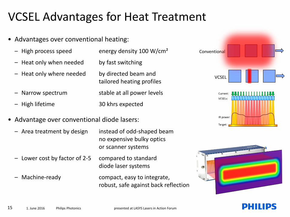
VCSEL Advantages for Heat Treatment
• Advantages over conventional heating:
– High process speed energy density 100 W/cm²
– Heat only when needed by fast switching
– Heat only where needed by directed beam and tailored heating profiles
– Narrow spectrum stable at all power levels
– High lifetime 30 khrs expected
• Advantage over conventional diode lasers:
– Area treatment by design instead of odd-shaped beam no expensive bulky optics or scanner systems
– Lower cost by factor of 2-5 compared to standard diode laser systems
– Machine-ready compact, easy to integrate,robust, safe against back reflection
VCSEL
Conventional
16 Philips Photonics presented at LASYS Lasers in Action Forum1. June 2016
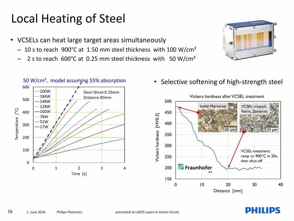
• VCSELs can heat large target areas simultaneously
– 10 s to reach 900°C at 1.50 mm steel thickness with 100 W/cm²
– 2 s to reach 600°C at 0.25 mm steel thickness with 50 W/cm²
Local Heating of Steel
50 W/cm², model assuming 55% absorption • Selective softening of high-strength steel

17 Philips Photonics presented at LASYS Lasers in Action Forum1. June 2016
• Successful VCSEL system integration in a commercial Fast Firing Line of Rehm Thermal Systems
• Test wafers were processed at Rehmand characterized by Fraunhofer ISE
• Exerimental results:
– Ultrafast temperature rise in 4 cm treatment length
– Benchmark cell efficiency reached
– New compact machine concepts may become feasible
Metallization Line Sintering In Solar Cell Production
1050 K/s

18 Philips Photonics presented at LASYS Lasers in Action Forum1. June 2016
• Example forheat treatmentup to 1000 °C
Solar Cell Treatment

19 Philips Photonics presented at LASYS Lasers in Action Forum1. June 2016
• Test conditions:
– Standard VCSEL Module with 1.6kW IR power (980nm)
– Pressurized sample holder
– Samples: PP and PBT
• Simultaneous welding with 1s treatment time
Plastics Welding
Large area welding of PBT
absorbent
Localized heating zone
Lap Joint
transparent
Test pattern for microfluidic application
courtesy of

20 Philips Photonics presented at LASYS Lasers in Action Forum1. June 2016
• Test conditions:
– Standard VCSEL Module with 1.6kW IR power (980nm)
– Tests stationary and with linear motion
• Results:
– very good joining quality possible
– Black foam without absorber foil
– Colored or white foam with absorber layer
Foam Weldinglaser beam
glass plate
white foam
colored foam
absorber
holder
Perfect connection
Welding examples:
black foam without absorber foil colored foam with absorber foil

21 Philips Photonics presented at LASYS Lasers in Action Forum1. June 2016
• VCSEL modules integrated on the tape-laying head
– 100W/cm² power density enabling high speed process
– Controllable spatial heating profile
– Controllable dynamic heating profile
– Closed-loop control possible
Carbon Fiber Placement
Courtesy Fraunhofer IPTCourtesy Fraunhofer IPT
1.6kW compact VCSEL module integrated into tape-laying equipment

22 Philips Photonics presented at LASYS Lasers in Action Forum1. June 2016
Test setup at Fraunhofer IPT
Carbon Fiber Placement
Consolidation roller Tape
VCSEL module
Substrate
Ring

23 Philips Photonics presented at LASYS Lasers in Action Forum1. June 2016
• Compact triangular form
– Water cooling connection to module sides
– Electrical connections adaptable to requirements
Compact Module Concept for Fiber Placement
Example module 9.6 kW IR • 24 VCSEL emitters• emission area 209 x 40 mm²
Potential configurations for fiber placement:

24 Philips Photonics presented at LASYS Lasers in Action Forum1. June 2016
VCSEL Module
Panel
Roller
• High-quality solution for joining edge bandsto wooden furniture panels
– Plastics welding process yielding best edge quality
– Tight seal by laser heating of special edge band
• Requirements:
– high process speed > 15 m/min
– direct heating with good uniformity
– fast reconfiguration to material type and size
– fast switching, precise power control
– harsh environmental conditions
• Very limited volume available for laser module Redesign of the standard laser housing
Application Example:
Laser Edging of Furniture Panels
?

25 Philips Photonics presented at LASYS Lasers in Action Forum1. June 2016
High power VCSEL system is integrated in professional woodworking machines (IMA Klessmann GmbH)
– Fast development time of the VCSEL module within 3 months
– Uniform direct heating, no optics
– Electronic control of heating zones
– Robust system operated in harsh environment
– Much lower cost than existing laser solutions
Seamless Laser Edging of Furniture Panels – IMALUX

26 Philips Photonics presented at LASYS Lasers in Action Forum1. June 2016
High power VCSEL systems are offering attractivesolutions for industrial thermal processes
• High power density, enabling fast processing
• Precisely controllable, in time and spatially
• Scalable to any power level
• Compact, robust and easy to integrate
• Lower cost than conventional laser systems
Potential application fields
– Plastics welding & forming
– Composite manufacturing
– Coatings, curing, ...
– Photovoltaics
– Sheet & coil treatment
– ... ?
Conclusions

27 Philips Photonics presented at LASYS Lasers in Action Forum1. June 2016