high power ups achieves significant size and weight ... power ups achieves significant size and...
TRANSCRIPT
WP153004EN www.eaton.com/powerquality May 2013
High Power UPS Achieves Significant Size and Weight
Reductions While Enhancing Performance
Executive summary
Today’s transformerless UPSs are not only significantly smaller and lighter than transformer-based systems, but also more efficient, more reliable and better equipped to limit fault current. In addition, they enable companies to capitalize on sophisticated features like the Energy Saver System and Variable Module Management System, which add reliability via reduction of mechanical complexity while lowering power costs. As a result, today’s transformerless UPS designs outnumber older technologies by a factor of two to one for new installations in North American data centers.
This white paper discusses the technical benefits of transformerless UPSs and details the advantages they offer.
Table of contents
A brief history of transformerless UPS technology ................................................................................ 2 Transformerless UPSs: A growing trend .................................................................................................. 2 Comparison of transformer-based and transformerless UPSs.............................................................. 2 Benefits of transformerless UPSs versus legacy designs ..................................................................... 2 THD and transformerless UPS designs .................................................................................................... 4 Battery management advantages of a transformerless UPS ................................................................. 6 Comparative size and weight of magnetic components ......................................................................... 6 Transformerless UPSs aren’t all equal ..................................................................................................... 9 Conclusion ................................................................................................................................................... 9 About Eaton ................................................................................................................................................. 9 Appendix A: Ten common myths about transformer-based versus transformerless UPSs ............ 10

Page 2 of 12
WP153004EN www.eaton.com/powerquality May 2013
A brief history of transformerless UPS technology
First appearing at lower power levels, transformerless UPS designs have been around for two decades. A vast majority of designs below 300 kVA are now transformerless, meaning that the UPS does not contain power line frequency magnetics (transformers or inductors). This transformerless design trend encompasses even higher power levels because power line magnetics are both material and labor intensive. On the other hand, the high frequency power processing needed is technology intensive. In general, advances in technology mature sufficiently to support improved value to the customer without sacrificing needed reliability. Once that point is reached, the technology-intensive design becomes the preferred value leader. Technological advances in technology have had a similar impact upon switch mode power supplies such as those used in servers, storage and networking gear.
Transformerless UPSs: A growing trend
At higher power levels reaching above 30 kVA and now as high as 1100 kVA, the challenge is to switch high currents rapidly at high voltages without high losses or excessive peak voltages. Over the last decade, high power IGBTs have matured enough to allow conversion frequencies of 10 kHz and above without large sacrifices in efficiency at these higher power levels. In addition, some creative control strategies permit further reduction of switching losses to the point where the transformerless UPS is superior to an older technology UPS when measured in terms of system efficiency.
Comparison of transformer-based and transformerless UPSs
Feature Transformer-based UPS Transformerless UPS
Weight and size Typically 25 percent less weight and 40 percent smaller footprint
Efficiency 90 to 93 percent 92 to 97 percent
Energy saver mode Less efficient, slow to transition 99 percent efficient, 2ms transition time
4-wire output availability Yes Yes
Separately-divided source Not when on bypass Not when on battery
Support for high-resistance ground (HRG) sources
Yes, with reduced HRG benefit Yes, with HRG fault tolerance preserved
Reliability (MTBF) Lower Higher, due to lower component count
Ability to limit fault current and mitigate arc flash
Good Better, due to faster detection and isolation (not slowed by output impedance)
Generator compatibility Requires larger filter, contactor and generator
Allows closely-sized generator and both reduces part count and raises efficiency by not requiring a 12-pulse rectifier or input filter
Benefits of transformerless UPSs versus legacy designs
Figure 1 illustrates the basic topology of the legacy and transformerless technology UPS powertrain. A phase-controlled rectifier, while efficient and cost effective, produces large harmonic input currents and reduced input power factor which is unacceptable at many sites and incompatible with some generators. Large input inductors and harmonic filters are needed to bring the harmonics down to 5 to 10 percent total harmonic distortion (THD) and power factor (PF) up to >0.99 PF. These components add cost and weight and increase footprint, while the large numbers of capacitors reduce mean time between failures (MTBF). In addition, they do not hold THD down and PF up over a wide load range. They are typically effective only above 60 percent of full load. At light loads below approximately 40 percent, the input PF can actually become leading and will cause incompatibility with generators. The PF also varies with line voltage but is only specified at nominal line.
Page 3 of 12
WP153004EN www.eaton.com/powerquality May 2013
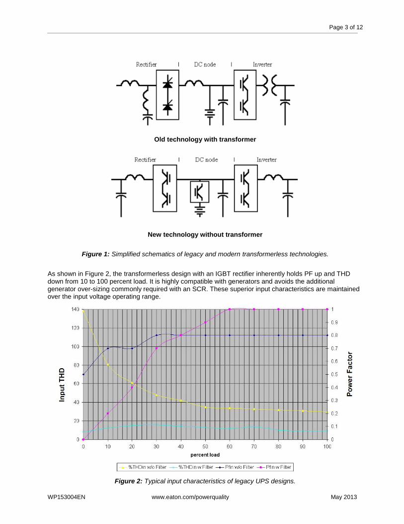
Old technology with transformer
New technology without transformer
Figure 1: Simplified schematics of legacy and modern transformerless technologies.
As shown in Figure 2, the transformerless design with an IGBT rectifier inherently holds PF up and THD down from 10 to 100 percent load. It is highly compatible with generators and avoids the additional generator over-sizing commonly required with an SCR. These superior input characteristics are maintained over the input voltage operating range.
Figure 2: Typical input characteristics of legacy UPS designs.

Page 4 of 12
WP153004EN www.eaton.com/powerquality May 2013
Typical 6 SCR input current with 30 percent or more THD with di/dt limited by input inductors.
The higher switching frequencies used in the transformerless allow the use of smaller filter inductors and faster response times with improved waveform integrity:
Figure 3: Typical input characteristics of transformerless UPS designs.
THD and transformerless UPS designs
In regards to harmonic distortion, the severity level depends upon the particular application and location. For example, a 10 percent distortion component at a low frequency causes far less voltage distortion than one at a high frequency. Without adequate input filtering, a rapid di/dt (current spike) resulting from SCR firing can cause severe line voltage notching and interfere with adjacent equipment. In fact, it takes more than 14 percent THD before the input PF is reduced below 0.990 by the THD alone. (See Figure 4 below.)
PF_true vs THD
0.955
0.960
0.965
0.970
0.975
0.980
0.985
0.990
0.995
1.000
1.005
0 5 10 15 20 25 30
%THD
PF
_tr
ue
Pftrue
Figure 4: True power factor versus THD.

Page 5 of 12
WP153004EN www.eaton.com/powerquality May 2013
Figure 5: Typical input and output waveforms of a transformerless topology UPS.
The powertrain in Figure 6 shows that an output neutral can be generated along with phase voltages without a transformer. While only three-wire input is needed for online operation, a neutral connection is needed to support bypass operation or phase-to-neutral loads. In the legacy topology, a Delta to Wye transformer is typically used to generate the output neutral.
Figure 6: Powertrain that does not require transformers.

Page 6 of 12
WP153004EN www.eaton.com/powerquality May 2013
Battery management advantages of a transformerless UPS
Note that a half bridge converter can control battery voltage independent of bus voltage and also allows a range of battery voltages (e.g. 192 through 240 cells) to be accommodated. This converter also enables the battery to rest in an open circuit state to avoid continuous ripple current and the accelerated aging (especially at elevated temperatures) resulting from floating at a voltage significantly higher than open circuit voltage. With these additional capabilities, advanced battery management (ABM®) technology and other charging techniques can be more effective in extending battery service life.
The IGBT rectifier stage supports the power drawn from the line while the Inverter stage supports the output current. With an input PF of >0.99, a load power up to 90 percent of rated kVA can be supported while maintaining ample reserve to recharge the battery. During periods of reduced line voltage, some recharge power is given up to ensure continued to support of output load. When the line level returns full/fast recharge capability will be restored.
With a SMALL Inductor/Capacitor (LC) low pass filter at the input, even the moderate di/dt changes in the input inductors are prevented from disturbing the line voltage – just as they are filtered at the output voltage by the same LC filter.
Comparative size and weight of magnetic components
An example of the size and weight reductions realized by using a transformerless design is shown in Picture 1, which displays the “magnetics package” (mag pak) for a conventional topology UPS. The output transformer, input line inductors, DC bus choke, output filter inductors and input harmonic filter inductors are included. Not only is it very heavy, but it is also a significant contributor to the size of the overall unit. The size and obvious weight difference in legacy components versus new transformerless technology is visually apparent when the units are compared side by side.
Transformerless mag pak Transformer-based mag pak
Picture 1: Illustration of comparative size of magnetics package (mag pak) for a 275 kVA UPS.
Page 7 of 12
WP153004EN www.eaton.com/powerquality May 2013
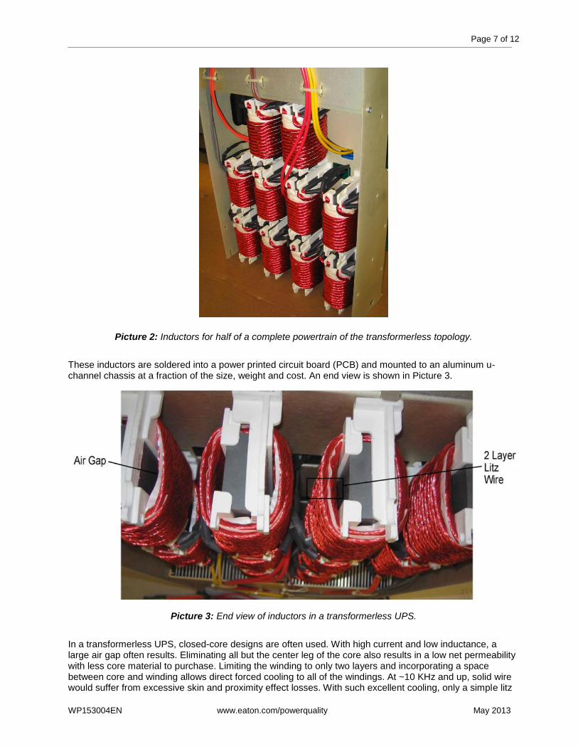
Picture 2: Inductors for half of a complete powertrain of the transformerless topology.
These inductors are soldered into a power printed circuit board (PCB) and mounted to an aluminum u-channel chassis at a fraction of the size, weight and cost. An end view is shown in Picture 3.
Picture 3: End view of inductors in a transformerless UPS.
In a transformerless UPS, closed-core designs are often used. With high current and low inductance, a large air gap often results. Eliminating all but the center leg of the core also results in a low net permeability with less core material to purchase. Limiting the winding to only two layers and incorporating a space between core and winding allows direct forced cooling to all of the windings. At ~10 KHz and up, solid wire would suffer from excessive skin and proximity effect losses. With such excellent cooling, only a simple litz

Page 8 of 12
WP153004EN www.eaton.com/powerquality May 2013
wire is needed at a fraction of the cost of traditional multi-layered litz. A ferrite core generates very low losses and avoids being heated by the winding. Used in pairs, the far field can be reduced while gaining ~15 percent useful inductance by orienting in anti-parallel configurations. (See Figure 7 below.)
Figure 7: Anti-parallel field.
Figure 8: Parallel field. With the far field reduced and an aluminum chassis containing the flux, the oft-anticipated interference problems with stray magnetic fields are avoided.

Page 9 of 12
WP153004EN www.eaton.com/powerquality May 2013
Transformerless UPSs aren’t all equal
Transformerless UPSs offer many advantages over transformer-based systems, but they’re not all the same. Decision-makers should insist on the following characteristics when selecting a transformerless UPS for their mission-critical application: 1. Low size and weight. Transformerless UPSs should be significantly smaller and lighter than transformer-based products, and not only because they don’t contain a bulky transformer. The UPS should also feature compact magnetics (such as inductors, chokes and ferrites) as well as airflow improvements that minimize the size and weight of heat sinks and reduce the number of fans required for cooling. Note that in addition to saving space these enhancements improve mechanical reliability too. 2. Ability to operate from grounded wye and even HRG sources. The proper handling of the neutral should be described clearly in the installation documentation. Special attention should be paid to upstream and downstream fault performance, and the UPS should be able to feed 4-wire loads, such as 208/120VAC and 400/230VAC. 3. Short transition times from high-efficiency to conventional operating mode. As it doesn’t need to magnetize an output transformer when transitioning between high-efficiency and conventional operation, a transformerless UPS should be able to complete the transition in about 2 milliseconds. Greater than 10 mSec transition times may cause problems for downstream static switches or the supported IT equipment itself.
Conclusion
The transformerless topology with small and lightweight filter inductors, high performance IGBTs in both inverter and rectifier and advanced control strategies can bring improved performance and value. Compared to legacy UPS topology designs, a transformerless UPS is typically only 25 percent the weight and occupies 60 percent of the footprint
1. Low input THD (<4.5 percent at full load) and high input power
factor (>0.99) are supported down to nearly 10 percent load without the need for an additional input filter. In addition, full load efficiency can reach 95 percent and above. The packaging can be designed so that cooling and wiring do not require side or rear access or clearance. With these new benefits, this technology-intensive design will become the preferred topology.
About Eaton
Eaton is a diversified power management company providing energy-efficient solutions that help our customers effectively manage electrical, hydraulic and mechanical power. With 2012 sales of $16.3 billion, Eaton is a global technology leader in electrical products, systems and services for power quality, distribution and control, power transmission, lighting and wiring products; hydraulics components, systems and services for industrial and mobile equipment; aerospace fuel, hydraulics and pneumatic systems for commercial and military use; and truck and automotive drivetrain and powertrain systems for performance, fuel economy and safety. Eaton acquired Cooper Industries plc in 2012. Eaton has approximately 103,000 employees and sells products to customers in more than 175 countries. For more information, visit www.eaton.com.
1 Eaton 9395 UPS used for comparison

Page 10 of 12
WP153004EN www.eaton.com/powerquality May 2013
Appendix A: Ten common myths about transformer-based versus transformerless UPSs
1. The input and/or output transformer protects the rectifier and/or inverter SCRs from damage due to transients.
In the past, transformers were needed to provide proper voltage and act as a series impedance for SCR-based power rectifiers or inverters. Modern IGBT-based transistorized UPSs, however, do not require either voltage modification or transient protection. Furthermore, though SCRs and slower transistorized inverter controls were once helped by the transformers’ impedance during a fault, this is no longer necessary as today’s faster UPS controls act to protect the critical load by isolating the UPS within microseconds.
2. The input and output transformers in the UPS are required to “float” the rack-mounted battery, so it’s safer to service and safer for personnel who may accidentally touch a terminal.
It is never safe to touch an exposed battery terminal, whether it’s “floating” or not. In fact, a floating battery can easily create a false sense of safety.
Example 1: A floating battery could easily electrocute a technician if there were a spilled electrolyte short between a battery terminal and the metal rack. If a technician standing on the ground touched the relevant battery terminal, they would be exposed to potentially lethal voltages. That’s every bit as dangerous as a non-floating battery, and UPS transformers won't prevent it.
Moreover, even the input and output transformers in the UPS will not make the battery terminals safe to touch. Battery terminals should be treated with the same respect as the AC input and output terminals in the UPS. Rather than use large quantities of iron and copper to make batteries seem safe, transformerless UPS manufacturers simply recommend using battery terminal covers, as they are much less expensive than transformers and allow you to perform maintenance procedures with the battery breaker open.
Example 2: If a technician watering a floating battery creates an electrolyte track on cell #2 to the rack and then accidentally touches the terminal on battery cell #220, he or she will experience over 400 VDC and will conduct into ground whatever current their skin resistance allows. Even if you float your battery system, then, touching a terminal could still kill you. Though technicians are less likely to be electrocuted by a floating battery, it's still very risky.
A better approach is to avoid placing data center personnel in positions that could lead to accidental contact with a bare terminal by opening the DC string breaker and using plastic or rubber terminal covers.
How, after all, do data center operators protect people from dangerous AC input terminals? They use dead fronts and doors, which UL deems a safe approach. That approach works just as well for batteries—use terminal covers in place of dead fronts and if you must expose a terminal, open the breaker, just as if you were accessing an AC input terminal.
3. I can’t detect a “battery ground fault” alarm if my battery is not floating.
Actually, you can, and far more economically. A third-party ground fault detector device is roughly .05 percent the cost of a pair of transformers, and weighs a lot less too. Unlike transformers, moreover, it doesn’t impose an efficiency penalty either.
4. Transformers automatically provide galvanic isolation.
It has been a common misconception that the in-built output and input transformers required in SCR and SCR/IGBT UPSs automatically provide galvanic isolation to the load as an additional benefit.
This, in most cases, is not true. The main purpose of the output voltage transformer is for voltage conversion, not galvanic isolation of the neutral. As shown in Figure 9, typically the neutral of the UPS will be connected straight through, to simplify most site requirements of an earth-bonded neutral, in which the MEN link occurs upstream of the UPS at the main feeder board. Therefore, any galvanic isolation of the load neutral will not occur.
In addition, galvanic isolation cannot be obtained as the static switch devices are placed after the transformer, as shown in Figure 9 (remembering the static switch is designed to switch between the UPS inverter/transformer output and the input bypass supply). Any time the UPS transfers to static bypass

Page 11 of 12
WP153004EN www.eaton.com/powerquality May 2013
means a bonding of the two electrical sources. In the case of an off-line or standby UPS, this occurs in normal operation.
Galvanic isolation can be obtained by placing a double-wound transformer on the output of the UPS. The purpose is to isolate both inverter output and static switch output from the load. This is often marketed as a “bypass isolation transformer”, which is added on externally to the UPS. In fact, it highlights the truth that the bypass line is not isolated in normal internal operation.
Figure 9: System view of a typical SCR UPS.
5. The lack of an output transformer means I can’t bond neutral to ground in the UPS, so I might have neutral-to-ground or common mode noise problems.
Bonding the neutral to ground in a transformerless UPS is not recommended. If a neutral has been brought to the UPS from the bypass source, the UPS neutral should be connected to the source neutral but not bonded to ground. That said, for common mode noise isolation it is important to consider the following:
If the facility transformer (with its N-G bond) that feeds the UPS is close to the UPS then an additional transformer in the UPS is redundant.
If there is a power distribution unit (PDU) transformer or distribution transformer between the UPS and the critical load, then an additional transformer in the UPS is redundant.
Virtually all IT equipment manufactured in the last two decades has filtering which attenuates incoming common mode noise at a rate of about 10,000,000:1.
6. A transformer in the UPS means it will be better able to handle internal and external faults or short circuits.
This may have been true 20 years ago, but today’s transformerless UPSs have internal circuitry, fusing and fast DSP controls that enable them to handle internal shorts, external downstream faults and upstream faults, all while protecting the load and UPS internal components. Test results, waveforms and the real-world experiences of thousands of data center operators worldwide all confirm this.
7. A transformer in the UPS helps limit available fault currents and prevents arc flash issues.
The impedance produced by a UPS transformer will indeed limit fault currents and arc flash energy levels. But consider the following questions:
Is the UPS rated or marketed as an arc flash protection device?
No. The facility should be designed properly to limit available fault current. A fault on the output will transfer the UPS to bypass.
Does either type UPS limit fault current when on bypass?
No. There is no transformer in the UPS’s internal bypass path.
Do both types of UPS limit fault current when on inverter?
Yes. It’s called “electronic current limit”.
What device feeds the UPS?
Page 12 of 12
WP153004EN www.eaton.com/powerquality May 2013
A facility transformer.
What device does the UPS typically feed?
A PDU containing a transformer.
So if the UPS is already surrounded by transformers, before and after, why does the UPS need internal transformers to limit fault current?
In actuality, it doesn’t.
8. The UPS’s output transformer is necessary in order to prevent a “DC component” from appearing in the UPS output during an internal UPS failure.
Transformerless UPSs are designed with fast semiconductor fusing, and in some cases with a rotating vector sensing algorithm that instantaneously isolates and protects the UPS and will not allow a DC component to occur in the output under any operating or failure mode. In documented tests involving input rectifier short circuit faults, inverter IGBT faults and faults of both the positive and negative DC bus, the UPS always emerged undamaged and the load remained protected.
9. A transformerless UPS cannot protect the load in the event of a battery bus fault.
See the content in myth number 7 about DC fault tests.
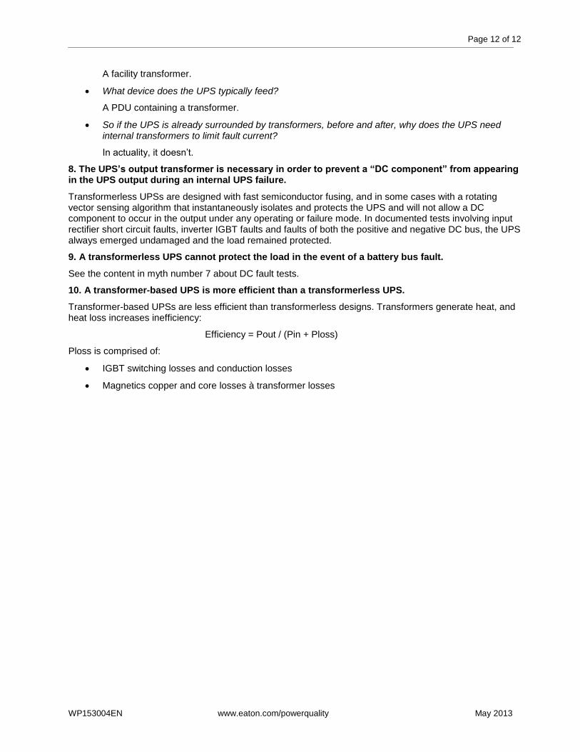
10. A transformer-based UPS is more efficient than a transformerless UPS.
Transformer-based UPSs are less efficient than transformerless designs. Transformers generate heat, and heat loss increases inefficiency:
Efficiency = Pout / (Pin + Ploss)
Ploss is comprised of:
IGBT switching losses and conduction losses
Magnetics copper and core losses à transformer losses