high-power positive electrode based on synergistic effect
TRANSCRIPT
MANUSCRIP
T
ACCEPTED
ACCEPTED MANUSCRIPT
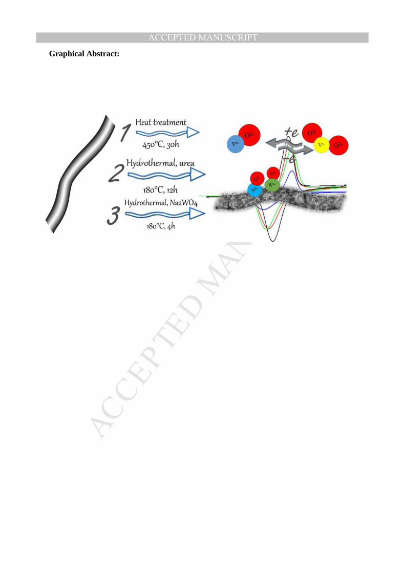
Graphical Abstract:
MANUSCRIP
T
ACCEPTED
ACCEPTED MANUSCRIPT
High-power positive electrode based on synergistic effect of N- and WO3 decorated
carbon felt for vanadium redox flow batteries
Mir Ghasem Hosseini a, b*1, Seyedabolfazl Mousavihashemi a, c, Sebastián Murcia-Lópezc,
Cristina Flox c*2, Teresa Andreu c, Joan Ramón Morante c, d
a Department of Physical Chemistry, Electrochemistry Research Laboratory, University of
Tabriz, Tabriz, Iran
b Engineering Faculty, Department of Materials Science and Nanotechnology, Near East
University, 99138, Nicosia, North Cyprus, Mersin 10, Turkey
c IREC, Catalonia Institute for Energy Research, Jardins de les Dones de Negre 1, Sant Adrià
de Besós, 08930 (Spain)
Facultat de Física, Universitat de Barcelona, C. Martí i Franqués, 1, 08028, Barcelona, Spain
1 * Corresponding author. Tel: +98 413 339 3138. E-mail: [email protected] (Mir Ghasem Hosseini)
2 * Corresponding author. Tel: +34 933 562 615. E-mail: [email protected] (Cristina Flox)

MANUSCRIP
T
ACCEPTED
ACCEPTED MANUSCRIPT
Abstract
Although Vanadium Redox Flow Battery (VRFB) is well suitable for grid-scale application,
their power-related cost must be reduced in order to boost the technology to the market,
allowing their widespread commercialization. One effective way to make the VRFB a
competitive and viable solution could be through the new strategies for improving the
electrocatalytic activity of the electrodes with enhanced electrolyte/electrode interface
characteristics. The greatly effective and enhanced-electron transfer could increase the
current density with the decrement of the stack size. Herein, we report the synergistic effect
demonstrated by N- and WO3- decorated carbon-based positive electrode, named HTNW
electrode, which demonstrates the feasibility of achieving: i) enhanced electrocatalytic
activity, indicating high rate towards VO2+/VO2+ couple (promotion of oxygen and electron
transfer processes), ii) decrement of the electron-transfer resistance from 75.62 Ω to 12.4 Ω
for the pristine electrode and HTNW electrodes, respectively; iii) 51% of the electrolyte
utilization ratio at high rates (i.e. 200 mA cm-2) with 70% of energy efficiency ; iv) increment
of more than 50% of the power–peak in comparison with HT electrode.

MANUSCRIP
T
ACCEPTED
ACCEPTED MANUSCRIPT
1. Introduction
Vanadium redox flow batteries (VRFB) are considered a prominent alternative to large-scale
energy storage because of their outstanding features compared to other energy storage
technologies (i.e. Lithium ion batteries) such as longer lifetime (10000 cycles), flexible
design, and minimum self-discharge. However, despite of their maturity, cost reduction is the
major challenge to overcome in order to achieve VRFB widespread application, including
renewable integration, smart grid uses and off-grid electrification areas. This is mainly
because the currently power-related cost is still too high, (state-of the art in VRFB €600/kW)
and the existing alternatives present low roundtrip electrochemical energy efficiency at high-
rates.
The power output is determined by size of the stacks through the number of cells and the
active area of the electrodes. The stack components (i.e. proton exchange membrane and
electrodes) directly define the performance of VRFB (e.g. high rate capability and long-term
stability) since they establish the polarization and the ohmic resistance. In particular, the
electrodes must facilitate the electron transfer process towards the positive and negative half-
cell reactions (1, 2). Consequently, by enhancing the electrochemical properties of the
electrodes the power density (i.e. current) can be increased, leading to a reduced stack size,
and, as a consequence, decreasing the power-related cost (SET plan targets for batteries
towards 2030 in EU €300/kW [1]).
VO2++2H++ e- VO2++ H2O E°=1.0 V (1)
V3++ e- V2+ E°= -0.26 V (2)
According to these reactions, the positive half-cell reaction (reaction 1) involves a kinetics
that requires the contribution of protons, the interchange of an oxygen atom and an electron
transfer process. The negative half-cell reaction involves only an electron transfer process
(reaction 2). Thus, the kinetics of the VO2+/VO2+ reactions becomes limited by the
availability of O-containing groups (i.e. number of active sites) that enhance this oxygen
interchange. Therefore, apart from the amount of oxygen functional groups (C=O, C-OH) on
the surface, other features related to the electrode activity, such as wettability and adsorption
of vanadium onto surface electrode become also decisive. It is worth mentioning that the
formation of Carbon- Nitrogen-Vanadium intermediate especially via quaternary and/or
oxidic nitrogen groups [4] is a key step for the enhancement of the electrocatalytic activity [2,
3], facilitating the electron transfer in the electrode/electrolyte interface

MANUSCRIP
T
ACCEPTED
ACCEPTED MANUSCRIPT
Intensive efforts have been made to improve the electrochemical activity of the carbon felts
(CF) as positive electrodes by enhancing the surface area and/or the electrical conductivity by
means of introducing several electrocatalysts. For example, MWCNTs [5], graphene
nanosheets and carbon nanofibers [6, 7], functionalization of carbon surface as N-and O-
containing groups [8], metals such as Pt [6], Ir [9] and Bi [10] and metal oxides Mn3O4[11,
12], WO3[13, 14], TiO2[15], CeO2[16], PbO2[17], and Nb2O5 [18] were deposited onto the
CF supports to prepare modified electrodes. However, although all this research
demonstrated an improvement in electrochemical kinetics, the enhanced power density is
rarely discussed in the literature as a complementary performance evaluation to the
charge/discharge experiments. Recently, significant work has been done by Mayrhuber et al.
to increase the power density by means of improving the mass-transport losses in carbon
paper electrode, achieving an increment in power density of 30% using perforated electrodes
in comparison with pristine carbon paper electrode [19]. In parallel, Liu et al. demonstrated
an increment in power density values of 16% using no-gap cell and air-treated electrodes
[20]. Despite this relevant research devoted to (1) improving the surface area with
functionalized electrodes, (2) enhancing mass-transport process and (3) designing novel
VRFB prototypes using no-gap architectures, the improvement of the power density output of
VRFB systems is still a major drawback preventing the cost from decreasing further.
In order to fill this gap and motivated by the idea to promote active sites for the adsorption of
vanadium ions and enhancements in the electron and oxygen transfer processes, our strategy
was based on the modification of the surface of carbon felt with the functionalization of N-
and WO3- containing groups. The performance of the VRFB has been evaluated as the
combined effect of the aforementioned functionalities for their advantages such as low cost,
easy preparation and high stability in sulfuric media in comparison with other metal oxides as
IrO3 or RuO2. In this study, we used a hydrothermal process with urea and Na2WO4·2H2O
precursors as an efficient methodology to produce stable and large amounts of N- and O-
functionalities. Moreover, the hydrothermal process is an environmentally friendly
technology, very suitable for large-scale production.
It is worth mentioning that the WO3-based electrodes have been extensively studied in the
literature as electrocatalysts for VRFB. However, the discussion is limited to fundamental
studies in three-electrode cell (Interlaced WO3-carbon nanotube nanocomposite
electrodeposited on graphite as a positive electrode in vanadium redox flow battery) or their
application in a flow cell with a very low current density (ca. 50 mAcm-2) [13]. Recently,
MANUSCRIP
T
ACCEPTED
ACCEPTED MANUSCRIPT
Kabtamu et al. studied the rate capability of WO3-based electrodes in VRFB up to 160 mA
cm-2, obtaining a very low electrolyte utilization ratio (i.e. 16 %) using WO3-based nanowire
electrodes [18].
2. Experimental
2. 1 Synthesis of the as-prepared electrodes
Materials: Rayon-based carbon Felt (CF) with 6 mm of thickness was purchased from
Societe Carbon-Lorraine. Urea with a quality BioReagent grade, sodium tungstate di-hydrate
(≥99.0%) and vanadium oxide sulphate (≥99.9%) were obtained from Sigma–Aldrich, while
sulphuric acid (95-98%), Chloridric acid (37%), oxalic acid (98%) were obtained from
Labkem. All materials were used as received without further purification. Figure 1 shows a
schematic representation of the synthesis process for the functionalization of the all
electrodes. Firstly, all as-prepared electrodes of CF were thermally activated at 450°C for 30
hours in oxygen atmosphere in order to remove impurities, denoted as HT electrode.
Consequently, HT electrode was modified by introducing N-functionalities, using a simple
and low-cost hydrothermal method. In this method, CF electrode was immersed in 80 mL
solution of 4 M urea in deionized water. Next, it was put into an ultrasonic bath for 30
minutes, allowing the penetration of the solution into the electrode and then it was poured
into a Teflon-lined autoclave reactor and the temperature was set to 180°C for 12 hours. After
that, the reactor was cooled down to room temperature and the sample was taken out and
washed with deionized water [21]. This electrode was labelled as HTN. The incorporation of
WO3-functionalities onto the surface of HT electrode was performed using 80 mL of
precursor solution based on 0.05 M of Na2WO4·2H2O salt in 2M HCl acidic media. The final
pH was adjusted to 2.4 by oxalic acid. A homogeneous solution was obtained after stirring
for 30 minutes. After that, the HT electrode was immersed in the solution and sonicated for
30 minutes. Finally, the hydrothermal reaction at 180°C with a duration of 3 hours was
carried out. After cooling down to room temperature, the felt was washed many times to
remove unattached WO3 particles [14]. This sample was labelled as HTW electrode. The
preparation of N and WO3 co-modified CF was carried out using the same hydrothermal
process applied to the HTN electrode. Finally, this electrode material was washed many times
and dried at 60°C. This electrode was labelled as HTNW.

MANUSCRIP
T
ACCEPTED
ACCEPTED MANUSCRIPT
Figure 1. Illustration of the electrode preparation.
2. 2 Materials characterization
The morphology of prepared felt electrodes was examined by FE-SEM (using a field
emission Zeiss Auriga® series instrument) with an accelerating voltage of 15 kV. The
elemental composition of felt samples was investigated by energy dispersive X-ray
spectroscopy (EDS) coupled with the SEM. The tungsten oxide crystal structure
characterization was measured in a Bruker D8 Advance diffractometer equipped with a Cu
Kα (1.54051 Å) radiation source. Bruker-Alpha FT-IR spectrophotometer in attenuated total
reflection (ATR) configuration was used to obtain ATR-FTIR spectrum of all as-prepared
felts in range of 375-4000 cm-1 with a resolution of 4 cm−1 and 24 scans. Dispersive
spectrometer Jobin-Yvon Lab Ram HR 800 with Olympus BXFM microscope optic was used
to obtain Raman spectra. The detector used was a CCD cooled to -70°C. Laser power on
samples was 0.5 mW. The chemical composition changes of the surface of the HTNW
electrode were analyzed by X-ray photoelectron spectroscopy (XPS) using a PHI instrument
model 5773 Multi-technique with A1 Kα radiation (1486.6 eV).
2. 3 Electrochemical tests
The electrochemical activity of prepared samples was investigated with a cyclic voltammetry
(CV) and electrochemical impedance spectroscopy (EIS). A piece of disk-shaped felt sample
(Diameter 8mm, thickness 6mm) was connected to a platinum wire and served as working
electrode. Hg/Hg2SO4/Sat. K2SO4 (0.664 V vs. SHE) and large surface area platinum mesh
were used as reference and counter electrodes, respectively. 0.05 M VOSO4 solution in 1 M
MANUSCRIP
T
ACCEPTED
ACCEPTED MANUSCRIPT
H2SO4 was used as three-electrode cell tests electrolyte. Different scan rates of 1 to 10 mV/s
were applied in CV tests to obtain voltammetry diagrams for VO2+/VO2+ redox couple to
investigate the diffusion reaction rates of different felt samples. EIS tests were studied by
applying alternating voltage of 10mV over frequency range of 100kHz to 10mHz at open
circuit potential (OCP). A Biologic® VMP-3 multi-channel potentiostat controlled by EC-
lab® software was used to perform electrochemical tests.
2. 4 Single-cell performance
The single-cell performance of as-prepared electrodes was evaluated in the VRFB cell, using
geometric area of electrodes of 3cm2 (i.e. positive electrode was as-prepared electrodes and
negative electrode: HT) with a Nafion 117 membrane between positive and negative
electrodes. 1.8 M VOSO4 in 3M H2SO4 electrolyte was used as starting electrolyte for
electrogeneration of other vanadium oxidation states as previously reported. The negative
electrolyte tank was bubbled with nitrogen gas for the duration of the experiment for oxygen
elimination. The flow rate of pumping positive and negative electrolytes into the cell was
30mL/min. The charge and discharge experiments were performed between 0.7 and 1.8 V in
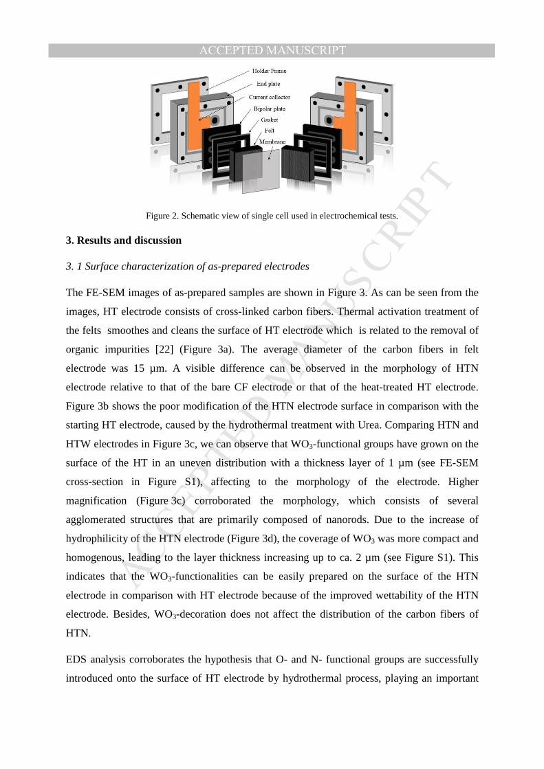
galvanostatic mode at 200mAcm-2. A schematic view of the used single cell is presented in
Figure 2. Charge and discharge profiles (cell potential vs. capacity) were used to obtain
electrolyte utilization ratio. A theoretical capacity of 965 mAh was calculated for 20 ml
electrolyte in each compartment. In order to identify the mechanism of the voltage losses and
the output of the voltage at specified current density, polarization curves were conducted
using current-steady steps. In all cases, the discharging polarization curve started with the
battery and, after that, the battery was discharged at the specified current density in the range
of 0 to 500 mAcm-2 for 30s, obtaining the output voltage. Finally, a rest period of 2 minutes
to a steady state at OCP was applied. The power density curves were obtained from the
product of output voltage and the corresponding current density.
MANUSCRIP
T
ACCEPTED
ACCEPTED MANUSCRIPT
Figure 2. Schematic view of single cell used in electrochemical tests.
3. Results and discussion
3. 1 Surface characterization of as-prepared electrodes
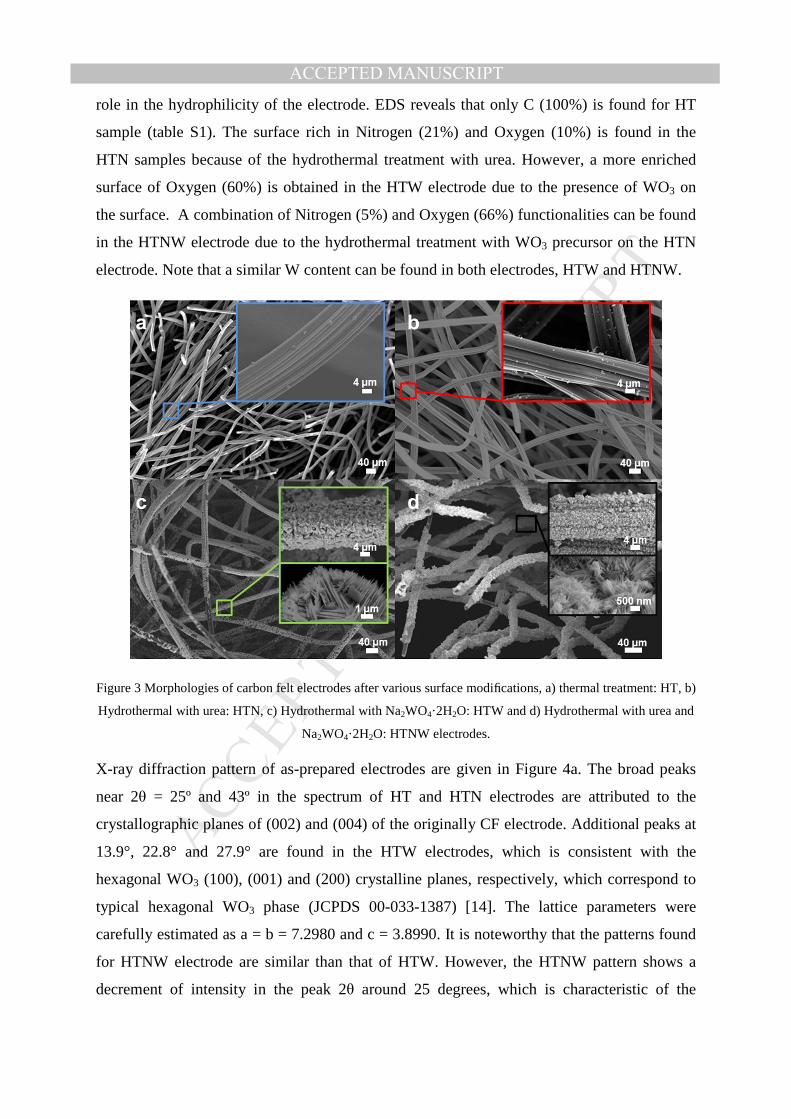
The FE-SEM images of as-prepared samples are shown in Figure 3. As can be seen from the
images, HT electrode consists of cross-linked carbon fibers. Thermal activation treatment of
the felts smoothes and cleans the surface of HT electrode which is related to the removal of
organic impurities [22] (Figure 3a). The average diameter of the carbon fibers in felt
electrode was 15 µm. A visible difference can be observed in the morphology of HTN
electrode relative to that of the bare CF electrode or that of the heat-treated HT electrode.
Figure 3b shows the poor modification of the HTN electrode surface in comparison with the
starting HT electrode, caused by the hydrothermal treatment with Urea. Comparing HTN and
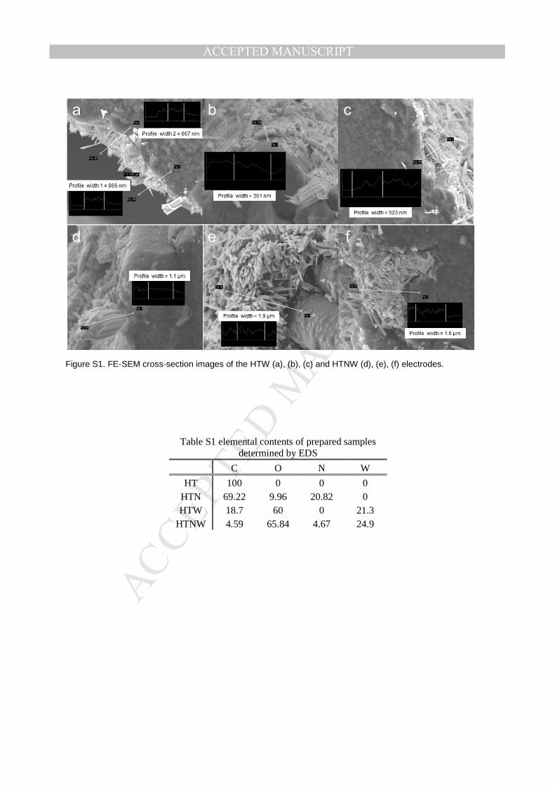
HTW electrodes in Figure 3c, we can observe that WO3-functional groups have grown on the
surface of the HT in an uneven distribution with a thickness layer of 1 µm (see FE-SEM
cross-section in Figure S1), affecting to the morphology of the electrode. Higher
magnification (Figure 3c) corroborated the morphology, which consists of several
agglomerated structures that are primarily composed of nanorods. Due to the increase of
hydrophilicity of the HTN electrode (Figure 3d), the coverage of WO3 was more compact and
homogenous, leading to the layer thickness increasing up to ca. 2 µm (see Figure S1). This
indicates that the WO3-functionalities can be easily prepared on the surface of the HTN
electrode in comparison with HT electrode because of the improved wettability of the HTN
electrode. Besides, WO3-decoration does not affect the distribution of the carbon fibers of
HTN.
EDS analysis corroborates the hypothesis that O- and N- functional groups are successfully
introduced onto the surface of HT electrode by hydrothermal process, playing an important
MANUSCRIP
T
ACCEPTED
ACCEPTED MANUSCRIPT
role in the hydrophilicity of the electrode. EDS reveals that only C (100%) is found for HT
sample (table S1). The surface rich in Nitrogen (21%) and Oxygen (10%) is found in the
HTN samples because of the hydrothermal treatment with urea. However, a more enriched
surface of Oxygen (60%) is obtained in the HTW electrode due to the presence of WO3 on
the surface. A combination of Nitrogen (5%) and Oxygen (66%) functionalities can be found
in the HTNW electrode due to the hydrothermal treatment with WO3 precursor on the HTN
electrode. Note that a similar W content can be found in both electrodes, HTW and HTNW.
Figure 3 Morphologies of carbon felt electrodes after various surface modifications, a) thermal treatment: HT, b)
Hydrothermal with urea: HTN, c) Hydrothermal with Na2WO4·2H2O: HTW and d) Hydrothermal with urea and
Na2WO4·2H2O: HTNW electrodes.
X-ray diffraction pattern of as-prepared electrodes are given in Figure 4a. The broad peaks
near 2θ = 25º and 43º in the spectrum of HT and HTN electrodes are attributed to the
crystallographic planes of (002) and (004) of the originally CF electrode. Additional peaks at
13.9°, 22.8° and 27.9° are found in the HTW electrodes, which is consistent with the
hexagonal WO3 (100), (001) and (200) crystalline planes, respectively, which correspond to
typical hexagonal WO3 phase (JCPDS 00-033-1387) [14]. The lattice parameters were
carefully estimated as a = b = 7.2980 and c = 3.8990. It is noteworthy that the patterns found
for HTNW electrode are similar than that of HTW. However, the HTNW pattern shows a
decrement of intensity in the peak 2θ around 25 degrees, which is characteristic of the

MANUSCRIP
T
ACCEPTED
ACCEPTED MANUSCRIPT
graphitic plate, also observed in the HTN electrode. The lattice obtained pattern for HTNW
revealed that the N-functionalities incorporate in the surface cause lattice distortion and, in
consequence, induce more defects.
For further inspection of the surface chemistry of the as-prepared CF electrodes, Fourier-
transform infrared spectroscopy (FT-IR) was performed. As clearly shown in the Figure 4b,
no significant peaks have been found in the HT electrode. However, several characteristic
peaks at 1150, 1588, 1678 and 3425 cm-1, appears in the sample HTN, corresponding to C-N-
H bending, NH2 scissoring, C=N bonding, and –NH, -NH2 stretching , respectively [23]. It is
a noteworthy that a strong band attributed to the presence of W-O-W bonds (stretching
vibration) is observed as a wide and sharp peak at ca. υ= 600 cm-1, in the HTW and HTNW
electrodes. Inside of this wide peak, can be differenced two peaks, which is attributed to two
different crystallinity of tungsten oxide in sample[24]. All samples show a weak peak at 3745
cm-1 as an indicator for hydroxide groups.
Figure 4. a) XRD pattern, b) ATR-FTIR spectra for as-prepared carbon felt samples
The structural changes in the graphitic structure of as–prepared were characterized by Raman
spectroscopy, as shown in Figure 5. Two well-defined peaks are clearly appreciated at Raman
shifts of 1350 cm-1 and 1580 cm-1, attributed to sp3 carbon bonds (D-band) and the carbon sp2
bonds (G-band), respectively. From the collected Raman spectra, the ratio of the intensities
(ID/IG) can be estimated, indicating the structure of the carbon defects of the electrodes
prepared. [25]. The intensity ratio of the HTNW electrode (ID/IG = 1.19); HTW electrode
(ID/IG = 1.25) and the HTN electrode (ID/IG = 1.37) are almost the same and, surprisingly,
highly superior to HT electrode (ID/IG = 0.19). This indicates that the implementation of
nitrogen and WO3 functionalities process contributes to increasing the ID/IG ratio, suggesting

MANUSCRIP
T
ACCEPTED
ACCEPTED MANUSCRIPT
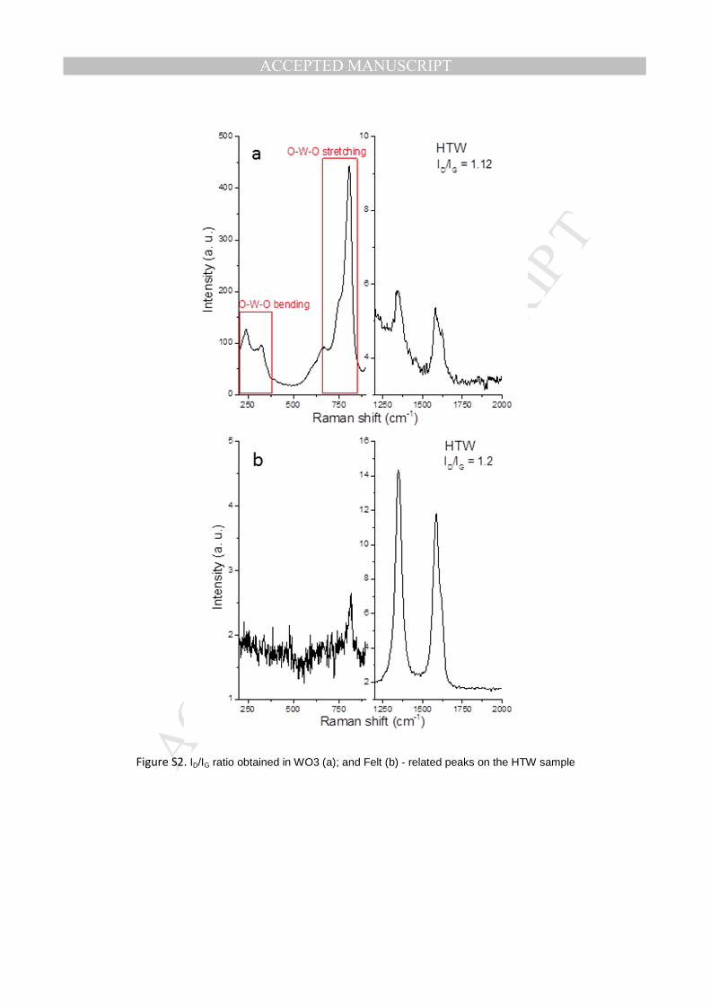
that the hydrothermal treatment causes a great increase of defective sites. No significant
difference in the ID/IG ratio, which is constant and ca. 1.2 (see Figure S2), can be appreciated
in the Raman spectra over the WO3-related peaks in comparison with the CF-related peaks in
the HTW electrode.
Figure 5. Raman spectra of the HT, HTN, HTW and HTNW electrodes
These results show that the HTNW electrode combines both, N and WO3-functionalities,
which have been successfully introduced on the surface on the CF. To complementary
investigate the chemical environment of Nitrogen on the surface structure of the HTN and
HTNW electrodes, Figure 6 shows the N binding energies from XPS analysis. The high-
resolution of the N 1s region shows the following contributions: 1) nitrogen atoms in the
pyridinic N-C groups (398.5 eV, N1); pyrrolic-N-C groups (399.8 eV, N2), quaternary N-C
groups (401.0 eV; N3), and pyridine-N-O-groups (402.5 eV, N4) [26, 27].

MANUSCRIP
T
ACCEPTED
ACCEPTED MANUSCRIPT
Figure 6. XPS survey for N1s spectra for; a) HTN, b) HTNW electrodes (N1: Pyridinic, N2: Pyrollic, N3: Quaternary, N4: Oxicidic).
Notably, the presence of the Pyridine-N-O-groups in the HTNW electrode related to the
ambient undergone the sample during the WO3 deposition the HTNW (Figure 6b). These
functionalities could promote the synergistic effect, based on the following assumptions: i)
The N-functionalities modify surface of the electrode in terms of wettability and thereby,
alters the chemisorption characteristics of the vanadium ions, together with WO3-
functionalities; ii) Incorporation of highly content of active sites in order to overcome the
rate-controlling step (i.e. the oxygen and electrode transfers) in the redox reaction
VO2+/VO2+.
3.2 Electrochemical properties
Cyclic voltammetry experiments at different scan rates were carried out to investigate
electrochemical behavior of prepared felt electrodes towards VO2+/VO2+ redox couples. The
electrochemical behavior improvement of these samples was evaluated through four
parameters, described as follow: i) current density values for oxidation and reduction peaks as
well as ratio of oxidation and reduction current density peaks (Ipa, Ipc) and ii) onset potential
for oxidation process ; iii) the ratio of oxidation and reduction peak current densities (Ipa/Ipc,
closed to 1 for reversible one electron process); iv) peak potential (Ea, Ec) and peak-to-peak
potential separation (∆Ep=59 mV for reversible one electron process) [30].
Figure 7 illustrates the 10th cycle of the CV curves, which well-defined peaks for both
oxidation and reduction processes can be appreciated in all as-prepared electrodes.
Comparing all electrodes, the oxidation and reduction peaks current density values of the as-
prepared electrodes are increasing in the following order (in parenthesis the Ipa and Ipc values

MANUSCRIP
T
ACCEPTED
ACCEPTED MANUSCRIPT
obtained from the voltammograms of the Figure 7 ): HT (Ipa =12.5, Ipc = 6.7 mA/cm2) <<
HTW (Ipa=22.9, Ipc = 15.6 mA/cm2) < HTN (Ipa = 27.4, Ipc= 16.1 mA/cm2) < HTNW electrode
(Ipa=29.7, Ipc = 22.6 mA/cm2). The low current density collected by the pristine electrode (i.e.
HT) indicates a poor electrocatalytic activity towards the VO2+/VO2+ reaction. Moreover, the
onset oxidation potential found was the highest than that of all samples (ca. 0.30 V vs
Hg/Hg2SO4). An improved electrocatalytic activity (i.e. higher Ipc and Ipc values as well as
lower onset potential) displayed the HTW electrode as consequence of the WO3-
functionalities. These functionalities could be beneficial for the activation of electron and
oxygen transfer processes towards the VO2+/VO2+ reaction. Significant increase of current
density as well as lower onset potential (ca. 0.26 V vs Hg/Hg2SO4 ) can be appreciated in the
HTN electrode due to the incorporation of the nitrogen functionalities. These N-
functionalities offers one lone pair of electron to effectively donor, which could facilitate the
electron transfer as well as the adsorption of vanadium [31, 32, 33]. The simultaneous
presence of WO3 and N-functionalities enhanced the electrocatalytic activity towards the
positive half-cell reaction leading to the highest current density performed and lower onset
potential ( ca. 0.23 V vs Hg/Hg2SO4 ).
Figure 7 CV diagrams of as-prepared electrodes in 0.05M VOSO4/1M H2SO4 solution at the scan rate of 1mV/s

MANUSCRIP
T
ACCEPTED
ACCEPTED MANUSCRIPT
The same trend was found with the Ipa/Ipc and ∆Ep values. The value of Ipa/Ipc for the
HTNW electrode is very close to ca.1.2, which is lower value than HTW (~1.7), HTN (~1.6)
and HT (~1.8) electrodes and the peak-to-peak separation potential (∆Ep) value is HTNW
(137 mV) whereas for the other samples are HTN (186 mV), HTW (230), and HT (249 mV).
The combination of these features, suggests the potential synergistic effect due to the
simultaneous modification of the HT electrode by WO3 and N groups. These functionalities
lead to remarkable higher electrocatalytic activity (i.e. higher reversibility and current density
collected) for the positive half-cell reaction than HTW, HTN and HT electrodes.
The mass-transfer features for as-prepared electrode have been assessed using Randles-
Secvic equation. Figure 8 despites the linear – relationship of the peak current densities
values for oxidation and reduction process as a function of square root of the scan rate. In all
as-prepared electrodes, peak currents densities are proved to be nearly proportional to the
square root in the whole range of scan rates investigated, thus revealing that process is
unequivocally controlled by the diffusion of the species in solution. In addition, the slope of
the HTNW electrode was higher for both, oxidation and reduction processes, comparing with
all electrodes studied, suggesting the improved mass-transfer reaction. The improved mass-
transfer reaction on HTNW electrode can be ascribed to the highest electrochemically surface
area due to the combination of WO3 and N functionalities.
Figure 8. Linear-relationship plot between the anodic and cathodic current density peaks vs scan rates.

MANUSCRIP
T
ACCEPTED
ACCEPTED MANUSCRIPT
Electrochemical impedance spectroscopy (EIS) data support our claims, as shown in Figure
7. In all as-prepared electrodes, a straight line at low frequencies and a semi-circle at high
frequencies are the components of the Nyquist impedance plot obtained, suggesting that the
reaction of VO2+ /VO2+ is a mixture of charge transfer and diffusion-controlled processes.
Consequently, the equivalent circuit shown in the inset of Figure 9 simulates the classical
Randles circuit for the aforementioned mixed control electrochemical process. The following
elements can be appreciate in the equivalent circuit: 1) the Rs element represents the bulk
electrolyte resistance; 2) Rct denotes charge transfer resistance occurred at the interface of
electrode material and electrolyte solution; 3) CPE-1 is ascribed to constant phase element,
which is related to the double-layer capacitance of the interface between electrode and
electrolyte, and 4) CPE-2 element represents the diffusion capacitance in pores of the
electrodes. The parameters obtained after the fitting data are listed in Table 1 for less than
10% error.
Figure 9. Nyquist impedance plots of the different carbon felt electrodes in a 0.05 M VOSO4/1.0 M H2SO4
solution at open-circuit potential.

MANUSCRIP
T
ACCEPTED
ACCEPTED MANUSCRIPT
No significant changes can be appreciated by the Rs values for all samples, indicating that the
poor influence of the treatment in the electrical properties of the electrodes. However, the
charge-transfer resistance (Rct) at the electrode/electrolyte interface is strongly influenced by
the treatment. Comparing all electrodes, a significant decrement of the Rct can be observed in
the following order (resistance values are given in parenthesis): HT (75.62 Ω) > HTW (57.66
Ω) > HTN (34.88 Ω) >> HTNW (12.4 Ω), indicating a faster electron transfer rate on the
surface of HTNW electrode. The same trends are evidenced for Y1 and Y2 values. The Y1
and Y2 values obtained for HTNW electrode were significantly the highest of all electrodes
tested, indicating that the combination of N-and WO3 -containing groups enhances the
electric double-layer capacitance of electrode/solution interface as well as diffusion
capacitance. Thus, the HTNW electrode favors the electron transfer process and facilitate the
absorption and the diffusion of vanadium ions in the pores of the electrode leading to higher
electrocatalytic effect, in accordance with the results obtained in CV analysis. These findings
can be probably attributed to the synergistic effect of the N- and WO3-functionalities that
could be beneficial for boosting the performance of VRFB in the market.
3.3 Capacity and power features in VRFB flow cell
All these characteristics remark that the simultaneous modification of the treated carbon felt
by WO3 and N-heteroatoms has a synergetic effect, creating higher surface area (i.e. highly
number of active sites) as well as facilitating the electron and oxygen transfer processes
towards the VO2+ /VO2+ reaction (i.e. lower charge transfer resistance values). Thus, the
higher active site density and the faster kinetics envisage the well-performance at higher
current densities without higher voltage losses. Consequently, these electrodes constitute a
clear alternative for increasing the power density capability and clearly could decrease the
cost of the stack.
Table 1. Parameters obtaining from fitting the Nyquits plots with the equivalent circuit model in inset of Figure 7
Rs (ohm) CPE-1 Rct (ohm) CPE-2
Sample
Y1 n1 Y2 n2
HT 0.75791 0.00193 0.96142 76.18 0.38637 0.76209
HTN 0.66482 0.00166 0.96764 35.89 0.73095 0.69781
HTW 0.54717 0.00165 0.9526 61.6 0.25353 0.68545
HTNW 0.78787 0.00489 0.9393 13 2.36 0.87898
MANUSCRIP
T
ACCEPTED
ACCEPTED MANUSCRIPT
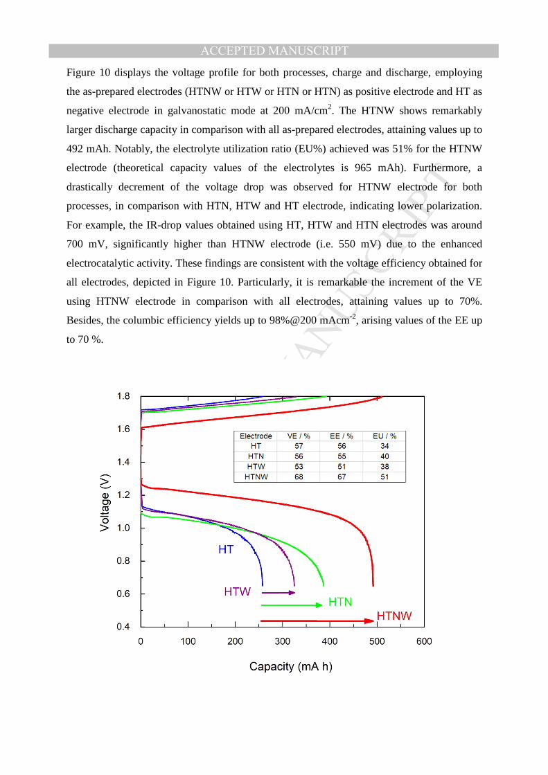
Figure 10 displays the voltage profile for both processes, charge and discharge, employing
the as-prepared electrodes (HTNW or HTW or HTN or HTN) as positive electrode and HT as
negative electrode in galvanostatic mode at 200 mA/cm2. The HTNW shows remarkably
larger discharge capacity in comparison with all as-prepared electrodes, attaining values up to
492 mAh. Notably, the electrolyte utilization ratio (EU%) achieved was 51% for the HTNW
electrode (theoretical capacity values of the electrolytes is 965 mAh). Furthermore, a
drastically decrement of the voltage drop was observed for HTNW electrode for both
processes, in comparison with HTN, HTW and HT electrode, indicating lower polarization.
For example, the IR-drop values obtained using HT, HTW and HTN electrodes was around
700 mV, significantly higher than HTNW electrode (i.e. 550 mV) due to the enhanced
electrocatalytic activity. These findings are consistent with the voltage efficiency obtained for
all electrodes, depicted in Figure 10. Particularly, it is remarkable the increment of the VE
using HTNW electrode in comparison with all electrodes, attaining values up to 70%.
Besides, the columbic efficiency yields up to 98%@200 mAcm-2, arising values of the EE up
to 70 %.
MANUSCRIP
T
ACCEPTED
ACCEPTED MANUSCRIPTFigure 10. Comparison of the electrochemical performance for all as prepared electrodes, showing the voltage
profiles for charge and discharge process at 200 mA cm-2.
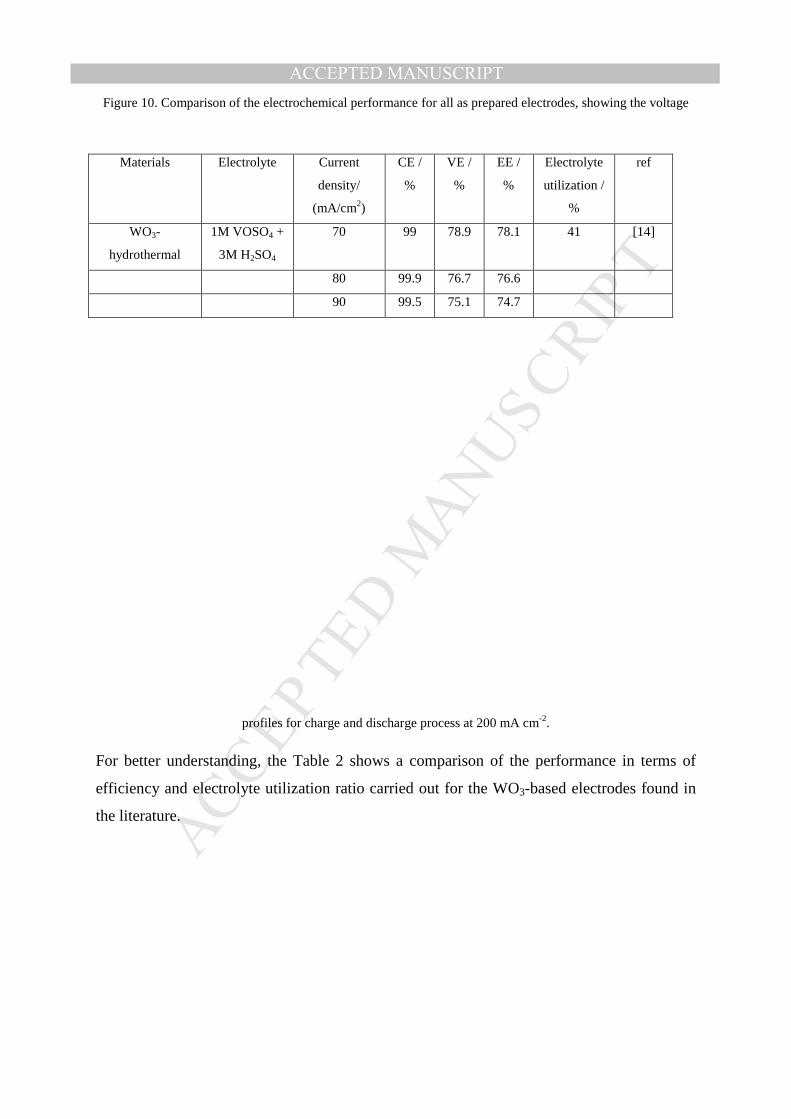
For better understanding, the Table 2 shows a comparison of the performance in terms of
efficiency and electrolyte utilization ratio carried out for the WO3-based electrodes found in
the literature.
Materials Electrolyte Current
density/
(mA/cm2)
CE /
%
VE /
%
EE /
%
Electrolyte
utilization /
%
ref
WO3-
hydrothermal
1M VOSO4 +
3M H2SO4
70 99 78.9 78.1 41 [14]
80 99.9 76.7 76.6
90 99.5 75.1 74.7

MANUSCRIP
T
ACCEPTED
ACCEPTED MANUSCRIPT
Table 2 Comparison of electrolyte, different efficiencies and electrolyte utilization percent of previously
reported WO3-based electrode materials
*Values calculated from the reference
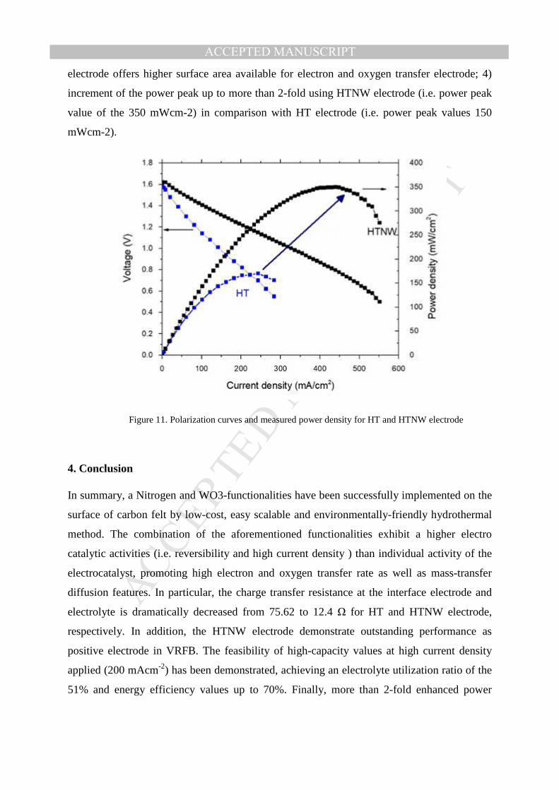
In order to evaluate the performance of the VRFB for power-related application using HTNW
electrodes, the peak power values determination has been evaluated. Figure 11 shows the
characteristic polarization curves obtained for VRFB using both electrodes, HT and HTNW.
Significantly differences can be appreciated in the performance originated by the following
voltage losses: 1) kinetic activation of electrode in the range of 0 to 100mA cm-2, 2) iR losses
or ohmic resistance in the range of 100 to 400 mAcm-2, associated with the contact resistant
of all components, ionic resistance and electrical resistance in electrodes, and 3) transport-
losses in the range of 425 to 500 mAcm-2 due to concentration for polarization, where a mass
transfer-limiting currents appears, associated with bulk reagent delivery to the electrode.
Comparing each region for both VFRB batteries and taking into account that the all elements
are the same with the exception of positive electrode; the following features can be draw: 1)
HT electrode originates greatly dramatic voltage drop, raising a kinetics more favorable in
VRFB using HTNW electrode; 2) using HT electrodes lead to poor electrocatalytic activity
than HTNW electrode in accordance with the VE trend; 3) The limiting current values are
200 and 400 mA cm-2 for HT and HTNW electrodes, respectively, which indicates substantial
improvement mass-transport limitation of the HTNW electrodes, leading to the HTNW
100 99.8 72.2 72.0
WO3/SAC 1.5 M VOSO4
+ 3M H2SO4
50 94.5 85.2 80.5 70 [13]
WO3/ Nanowire/
Graphene/foam
1.6 M VOSO4
+ 2.5M
H2SO4
40 90.7 92.3 83.7 63 [34]
80 95.0 83.7 79.5 66
120 96.2 75.9 73.0 39
160 98.2 68.8 67.6 20*
Nb-Doped
Hexagonal WO3
1.6 M VOSO4
+ 2.5M
H2SO4
40 92.4 92.1 85.1 15 [18]
80 93.2 83.8 78.1 13
120 95.1 75.0 71.3 9
160 95.3 69.1 65.8 4*
Nitrogen-tungsten
oxide
1.8 M VOSO4
+ 3M H2SO4
200 96.3 67.9 65.4 51 This
work
MANUSCRIP
T
ACCEPTED
ACCEPTED MANUSCRIPT
electrode offers higher surface area available for electron and oxygen transfer electrode; 4)
increment of the power peak up to more than 2-fold using HTNW electrode (i.e. power peak
value of the 350 mWcm-2) in comparison with HT electrode (i.e. power peak values 150
mWcm-2).
Figure 11. Polarization curves and measured power density for HT and HTNW electrode
4. Conclusion
In summary, a Nitrogen and WO3-functionalities have been successfully implemented on the
surface of carbon felt by low-cost, easy scalable and environmentally-friendly hydrothermal
method. The combination of the aforementioned functionalities exhibit a higher electro
catalytic activities (i.e. reversibility and high current density ) than individual activity of the
electrocatalyst, promoting high electron and oxygen transfer rate as well as mass-transfer
diffusion features. In particular, the charge transfer resistance at the interface electrode and
electrolyte is dramatically decreased from 75.62 to 12.4 Ω for HT and HTNW electrode,
respectively. In addition, the HTNW electrode demonstrate outstanding performance as
positive electrode in VRFB. The feasibility of high-capacity values at high current density
applied (200 mAcm-2) has been demonstrated, achieving an electrolyte utilization ratio of the
51% and energy efficiency values up to 70%. Finally, more than 2-fold enhanced power
MANUSCRIP
T
ACCEPTED
ACCEPTED MANUSCRIPT
density can be easily achieved for the VRFB using HTNW electrode in comparison with HT
electrode, allowing to decrement of the stack size as well as cost of the battery.
Acknowledgement
Authors thank Generalitat de Catalunya for financial support through the CERCA Program,
MINECO for additional support by coordinated project ENE2016-80788-C5-5-R and
Fundación Ramón Areces funding through BAT-LIMET project. S.M.L. for his Juan de la
Cierva, Formación fellowship (FJCI-2014-19745). S.M.L. thanks MINECO for his Juan de la
Cierva – Formación fellowship (FJCI-2014-19745).
Author contributions:
S.M. prepared the electrodes and carried out the characterization of electrodes by FE-SEM;
XRD, Raman, ATR-FTIR and electrochemical experiments. S.M.L has contributed in the
synthesis and characterization of the samples. M.G.H reported on the data interpretation; CF,
TA and J.R.M. interpreted all data discussion and arguments. C.F. and J.R.M. led the
research. All authors participated to the article preparation.
References.
1. Darling, R.M., et al., Pathways to low-cost electrochemical energy storage: a comparison of aqueous and nonaqueous flow batteries. Energy & Environmental Science, 2014. 7(11): p. 3459-3477.
2. Sun, B. and M. Skyllas-Kazacos, Chemical modification of graphite electrode materials for vanadium redox flow battery application—part II. Acid treatments. Electrochimica Acta, 1992. 37(13): p. 2459-2465.
3. Sun, B. and M. Skyllas-Kazacos, Modification of graphite electrode materials for vanadium redox flow battery application—I. Thermal treatment. Electrochimica Acta, 1992. 37(7): p. 1253-1260.
4. Jin, J., et al., Identifying the active site in nitrogen-doped graphene for the VO2+/VO2+ redox reaction. ACS nano, 2013. 7(6): p. 4764-4773.
5. Huang, R.-H., et al., Investigation of active electrodes modified with platinum/multiwalled carbon nanotube for vanadium redox flow battery. Journal of the Electrochemical Society, 2012. 159(10): p. A1579-A1586.
6. Flox, C., et al., Active nano-CuPt 3 electrocatalyst supported on graphene for enhancing reactions at the cathode in all-vanadium redox flow batteries. Carbon, 2012. 50(6): p. 2372-2374.
7. Cai, Y., et al., Graphene nanosheets-tungsten oxides composite for supercapacitor electrode. Ceramics International, 2014. 40(3): p. 4109-4116.
8. Huang, Y., et al., N, O Co-doped carbon felt for high-performance all-vanadium redox flow battery. International Journal of Hydrogen Energy, 2016.
9. Wang, W. and X. Wang, Investigation of Ir-modified carbon felt as the positive electrode of an all-vanadium redox flow battery. Electrochimica Acta, 2007. 52(24): p. 6755-6762.
10. Li, B., et al., Bismuth nanoparticle decorating graphite felt as a high-performance electrode for an all-vanadium redox flow battery. Nano letters, 2013. 13(3): p. 1330-1335.
MANUSCRIP
T
ACCEPTED
ACCEPTED MANUSCRIPT11. He, Z., et al., Mn 3 O 4 anchored on carbon nanotubes as an electrode reaction catalyst of V
(IV)/V (V) couple for vanadium redox flow batteries. Electrochimica Acta, 2015. 176: p. 1434-1440.
12. Ejigu, A., M. Edwards, and D.A. Walsh, Synergistic Catalyst–Support Interactions in a Graphene–Mn3O4 Electrocatalyst for Vanadium Redox Flow Batteries. ACS Catalysis, 2015. 5(12): p. 7122-7130.
13. Yao, C., et al., Carbon paper coated with supported tungsten trioxide as novel electrode for all-vanadium flow battery. Journal of Power Sources, 2012. 218: p. 455-461.
14. Shen, Y., et al., Electrochemical catalytic activity of tungsten trioxide-modified graphite felt toward VO 2+/VO 2+ redox reaction. Electrochimica Acta, 2014. 132: p. 37-41.
15. Vázquez‐Galván, J., et al., Hydrogen‐Treated Rutile TiO2 Shell in Graphite‐Core Structure as a Negative Electrode for High‐Performance Vanadium Redox Flow Batteries. ChemSusChem, 2017. 10(9): p. 2089-2098.
16. Zhou, H., et al., CeO 2 decorated graphite felt as a high-performance electrode for vanadium redox flow batteries. RSC Advances, 2014. 4(106): p. 61912-61918.
17. Wu, X., et al., PbO 2-modified graphite felt as the positive electrode for an all-vanadium redox flow battery. Journal of Power Sources, 2014. 250: p. 274-278.
18. Kabtamu, D.M., et al., Electrocatalytic activity of Nb-doped hexagonal WO 3 nanowire-modified graphite felt as a positive electrode for vanadium redox flow batteries. Journal of Materials Chemistry A, 2016. 4(29): p. 11472-11480.
19. Mayrhuber, I., et al., Laser-perforated carbon paper electrodes for improved mass-transport in high power density vanadium redox flow batteries. Journal of Power Sources, 2014. 260: p. 251-258.
20. Liu, Q., et al., High performance vanadium redox flow batteries with optimized electrode configuration and membrane selection. Journal of The Electrochemical Society, 2012. 159(8): p. A1246-A1252.
21. Sun, L., et al., Nitrogen-doped graphene with high nitrogen level via a one-step hydrothermal reaction of graphene oxide with urea for superior capacitive energy storage. Rsc Advances, 2012. 2(10): p. 4498-4506.
22. Liu, H., et al., An electrochemically activated graphite electrode with excellent kinetics for electrode processes of V (II)/V (III) and V (IV)/V (V) couples in a vanadium redox flow battery. RSC Advances, 2014. 4(98): p. 55666-55670.
23. Li, M. and J. Xue, Integrated synthesis of nitrogen-doped mesoporous carbon from melamine resins with superior performance in supercapacitors. The Journal of Physical Chemistry C, 2014. 118(5): p. 2507-2517.
24. Schieder, M., et al., Hierarchically porous tungsten oxide nanotubes with crystalline walls made of the metastable orthorhombic polymorph. Journal of Materials Chemistry A, 2013. 1(2): p. 381-387.
25. Cançado, L.G., et al., Quantifying defects in graphene via Raman spectroscopy at different excitation energies. Nano letters, 2011. 11(8): p. 3190-3196.
26. Guo, B., et al., Controllable N-doping of graphene. Nano letters, 2010. 10(12): p. 4975-4980. 27. Casanovas, J., et al., Origin of the large N 1s binding energy in X-ray photoelectron spectra
of calcined carbonaceous materials. Journal of the American Chemical Society, 1996. 118(34): p. 8071-8076.
28. Pels, J., et al., Evolution of nitrogen functionalities in carbonaceous materials during pyrolysis. Carbon, 1995. 33(11): p. 1641-1653.
29. Sharifi, T., et al., Formation of active sites for oxygen reduction reactions by transformation of nitrogen functionalities in nitrogen-doped carbon nanotubes. ACS nano, 2012. 6(10): p. 8904-8912.
30. Bard, A.J., et al., Electrochemical methods: fundamentals and applications. Vol. 2. 1980: Wiley New York.
31. Shao, Y., et al., Nitrogen-doped mesoporous carbon for energy storage in vanadium redox flow batteries. Journal Power Sources, 195, 13, 2010, 4375.
32. Flox, C et al., Thermo–chemical treatments based on NH3/O2 for improved graphite-based fiber electrodes in vanadium redox flow batteries. Carbon, 60, 2013, Pages 280-288

MANUSCRIP
T
ACCEPTED
ACCEPTED MANUSCRIPT33. Park, M. et al., Corn protein-derived nitrogen-doped carbon materials with oxygen-rich
functional groups: a highly efficient electrocatalyst for all-vanadium redox flow batteries.
Energy Environ. Sci., 2014, 7,3727 34. Kabtamu, D.M., et al., Three-dimensional annealed WO 3 nanowire/graphene foam as an
electrocatalytic material for all vanadium redox flow batteries. Sustainable Energy & Fuels, 2017.
MANUSCRIP
T
ACCEPTED
ACCEPTED MANUSCRIPT
Supplementary Information
High-power vanadium redox flow batteries based on synergistic effect of N- and WO3
decorated carbon felt in positive half-cell reaction
Mir Ghasem Hosseini a, b*1, Seyedabolfazl Mousavihashemi a, c, Sebastián Murcia-López c,
Cristina Flox c, *2, Teresa Andreu c, Joan Ramón Morante c, d
a Department of Physical Chemistry, Electrochemistry Research Laboratory, University of
Tabriz, Tabriz, Iran
b Engineering Faculty, Department of Materials Science and Nanotechnology, Near East
University, 99138, Nicosia, North Cyprus, Mersin 10, Turkey
c IREC, Catalonia Institute for Energy Research, Jardins de les Dones de Negre 1, Sant Adrià de
Besós, 08930 (Spain)
d Facultat de Física, Universitat de Barcelona, C. Martí i Franqués, 1, 08028, Barcelona, Spain
1 Corresponding author. Tel: +98 413 339 3138. E-mail: [email protected]
2 Corresponding author. Tel: +34 933 562 615. E-mail: [email protected]
MANUSCRIP
T
ACCEPTED
ACCEPTED MANUSCRIPT
Figure S1. FE-SEM cross-section images of the HTW (a), (b), (c) and HTNW (d), (e), (f) electrodes.
Table S1 elemental contents of prepared samples determined by EDS
C O N W
HT 100 0 0 0 HTN 69.22 9.96 20.82 0 HTW 18.7 60 0 21.3
HTNW 4.59 65.84 4.67 24.9
MANUSCRIP
T
ACCEPTED
ACCEPTED MANUSCRIPT
Figure S2. ID/IG ratio obtained in WO3 (a); and Felt (b) - related peaks on the HTW sample