high power model of isolator
TRANSCRIPT

High Power Model of Isolator
Rutambhara Yogi
www.europeanspallationsource.se16-06-24

Suppliers:
Many thanks to
Colleagues:
ESS: Mats Lindroos, David McGinnis, Anders Sunnesson, Morten Jensen, A. Johansson, Carlos Martins, Rihua Zeng, Rafael Montano, Chiara Marrelli,
Stevo Calic, Bruno Lagoguez, Staffan Ekström, Daniel Lundgreen, Carl Johan Hardh
FREIA: Rolf Wedberg, Lars Hermansson, Roger Ruber, Magnus Jobs & other colleagues
CERN: Eric Montesinos, Olivier Bruner
SNS: Crofford Mark
CWRF-2016 Rutambhara Yogi

Outline
• Brief introduction to ESS RF systems
• Circulator
• High power model of Isolator
• Effect of hot water cooling
CWRF-2016 Rutambhara Yogi

ESS: European Spallation Source
Being constructed in Lund, Southern Sweden
• Beam pulse width = 2.86 ms• Pulse repetition rate = 14 Hz • Peak proton beam power to the target = 125MW• Most intense pulsed neutron source in the world
: peak beam power larger by factor 5 compared to existing spallation facilities
CWRF-2016 Rutambhara Yogi
Europe’s one of the largest infrastructure

Power profile
84 High Beta cavities704 MHzNew development: IOT Backup solution: Klystron
26 Spoke Cavities,352 MHz400kWp*/20 kWavgTetrode
36 Medium Beta cavities704 MHz1.5MWp Klystron
1200 kWp*/60 kWavg
1200 kWp*/60 kWavg
Warm Linac 352 MHz-1 RFQ & 5 DTL:Klystrons3MWp* / 150 kWavg
*- Amplifier power with overhead
Coax uptocirculator,WR2300(hh )
WR1150
WR1150
- 3 MEBTSSA30kWp* / 1.5kWavg
WR2300 FH,WR2300 HH
1-5/8 inch coax
CWRF-2016 Rutambhara Yogi

Schematic of RFDS for MB/HB
CWRF-2016 Rutambhara Yogi
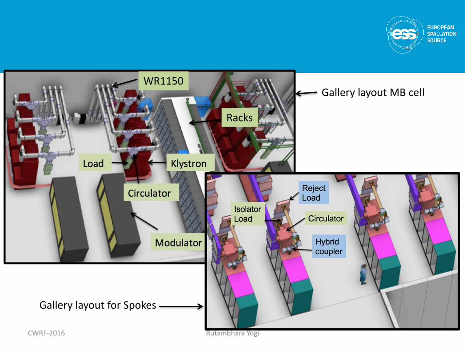
Racks
Gallery layout MB cell
Gallery layout for Spokes
CWRF-2016 Rutambhara Yogi
WR1150

RFDS layout for HB / MB cell
Space envelopeFor Circulator
Space envelope for Load
DC-1
DC-2DC-3
Removable wg section for PSS
Shutterswitch
RFDS layoutsame for MB/HB uptothis flange
IOT
CWRF-2016 Rutambhara Yogi

Circulator
Ideal Circulator: Like a round about
• Can have either 3 ports or 4 ports• Can use coaxial line / waveguide • Direction – clockwise / anti-clockwise
2.856 GHzP = 6 MWpPavg = 25 kW
Indigenous development done at SAMEER (India) in 1999. Installed on medical linac.
352 MHzP = 400 kWpPavg = 20 kW
Technology demonstrator for ESS spoke linac
CWRF-2016 Rutambhara Yogi

Circulator
• Nonreciprocal device
• Non-reciprocity is achieved due to ferrite
• Generally ferrite discs are used
• The discs can be either two discs or the multiples of two. Depends on power and thermal management
• Difference in μ+ and μ-, leads to non-reciprocity
CWRF-2016 Rutambhara Yogi

Transmissionfrom port 1 to port 2
IsolationFrom port 1 to port 3
CWRF-2016 Rutambhara Yogi
RF signal applied to the ferrite disc will generate two counter rotating waves, velocity dependent on propagation direction.

Construction of 3-port Circulator
CWRF-2016 Rutambhara Yogi

Ideal & Practical Isolator Isolator = Circulator + load
1
2
3
A
Load
Isolator
Amplifier is completely isolated from unwanted reflections
Ideal: Infinite Isolation Practical: Finite Isolation
A
1/1000 of power
Isolation = - 30 dB
Input power = 1500 kW
Only 1500 W = 1.5 kWwill reach amplifier ?
Load – Dissipate RF power from amplifier
CWRF-2016 Rutambhara Yogi

Load
A Cavity1 2
3
Isolation = 30 dBReturn loss = 30 dB
Load return loss = - 20 dB
1.5 kW
15 kW15 kW
Full reflection from cavity1.5 kW
Practical Isolator:
1500 kW
So we need a load with good Return loss
CWRF-2016 Rutambhara Yogi

High Power Model of Isolator
VT = V1 + V2 +V3
A small program is written for effective return loss calculation(Ref: ESS-0043091)
CWRF-2016 Rutambhara Yogi
Forward power /Circulation direction
Reflected power

Assumptions:
• Amplifier is perfectly matched.
• Higher order harmonics are not considered
• Uncertainties in S-parameter measurement not considered
• Only first order reflections are considered
• Worst case S-parameters and worst phases for S11eff calculations are considered.
CWRF-2016 Rutambhara Yogi

Parameters of circulator :S11= -30 dBS12 = -30 dBS21 = -0.5 dBNO higher order harmonics
Variation of Effective return loss of Isolator with return loss of load
AmplifierSpecification
We need a GOOD LOAD:
-30
CWRF-2016 Rutambhara Yogi

Worst Case Input Return Loss |S11eff| for |S11| = |S12| = 30dB (typical)
40 35 30 25 20 15 1030
25
20
15
10Input Return Loss vs. Load Return Loss
Load Return Loss RL
Inpu
t R
etu
rn L
oss
S11eff_neu_dB RL 10
30
20
10
30
20
20 log RL( )
CWRF-2016 Rutambhara Yogi

Variation of Effective return loss of Isolator with Phase of load return loss
Parameters of Circulator:S11 = -30 dBS12 = -26 dBS21= -0.05 dB
Parameters of Load:S11 = -30 dB
Value is not important.Phase of load return loss: stableWaveguide section can be added to get desired phase shift
CWRF-2016 Rutambhara Yogi

Testing of concept
Courtesy: Magnus Jobs at FREIA
Short
Towards VNA
Load with return lossvariation
• Trend of both the curves is same
• Good return loss when phase of load return loss at circulator is about 180 o
Further experimentation is planned with high powerCirculator and load at Lund test stand.
Experiment
CWRF-2016 Rutambhara Yogi

Additional boundary conditions in ESS:High temperature water cooled loads
CWRF-2016 Rutambhara Yogi
Initially Outlet temp Controlled to 60oC
Klystron
Load
Klystron
Load
N Number
Inlet
temp
50oC
Power dissipated across load
With HV on, RF off:ΔT ~ 10 oC
With HV on, RF on:Nominal beam operation,Klystron testing,
ΔT ~ 5 oC
Temperature rise due to power dissipation across collector:

Effect of unstable phase of load return loss
CWRF-2016 Rutambhara Yogi
• At same power level, cooling water temperature will vary from 50o C –80o C depending upon operational scenario.
• If phase of load return loss also varies, S11eff seen by amplifier will vary automatically, which may affect klystron stability.
# Klystron operation will be affected
Hence stable phase of load return loss will be preferred.

CWRF-2016 Rutambhara Yogi
New Load development for ESS
Hot water cooled loads
Frequency = 704 MHz
Power ≥ 1500 kWp
Pulse width = 3.5 ms
Pulse repetition rate = 14 Hz
Inlet water temp ≥ 50o C,
Outlet water temp ≤ 80o C
Temp: 50oC, 60oC, 80oC,
80oC: After 24 hours
S11 > 30 dB
BW > ±10 MHz
Return Loss Phase of Return Loss
ΔΦS11< 10o
Prototypes by MEGA, Thales will be delivered soon.

Thank you !
CWRF-2016 Rutambhara Yogi

Functional Requirements of RFDS
• Transportation of RF power from amplifier to thecavity coupler with minimum losses
• Dissipation of unwanted RF power during differentoperational scenario - Loads
• Protection of amplifier from the unwanted reflectionsduring filling and emptying of cavities or due to sparks– Circulator
• To satisfy requirements of personnel safety system(PSS) during different operational scenarios –removable waveguide, PSS flange, switch
• Detection of sparks in the RF system and give signalto the local protection system (LPS) – Arc Detectors
CWRF-2016 Rutambhara Yogi

• Measurement of forward and reflected power fromamplifier and cavity with the required accuracy,granularity - Directional couplers
• Take care of thermal expansion-contraction,dimensional changes in building layout such aschanges in the tunnel length, differential settlementof tunnel with respect to gallery etc – Bellows
• Simplification of cooling system design for energyrecovery – High temperature water cooled loads
• Depending on requirement, to ensure stableklystron operation by changing distance betweenklystron and circulator – extra flanges
CWRF-2016 Rutambhara Yogi

# Hot water cooled loads – New development for ESSBeing developed by three suppliers: AFT, MEGA and ThalesReceived AFT load in Lund test stand, MEGA and Thales load will be shipped by end of July / August
# Circulators being developed by three suppliers: AFT, MEGA and FMTFMT circulator will be shipped in a few days. DR for MEGA circulator: 27 JuneAFT circulator: Expected delivery by Aug end.
# High directivity directionalcouplers (D > 40 dB)- by MEGA
Prototype RFDS at ESS
3.8 km WaveguideE-elbows > 750H elbow > 550
For MB/HB Linac,
Huge requirement of waveguides and elbows !
CWRF-2016 Rutambhara Yogi

Flange and waveguide design
Waveguide extends throughthe flanges
Fabrication becomes extremely easy and avoids discontinuities
- Flanges will be welded along theperiphery (*)
- Surface cut along flange surface to ensure flatness, perpendicularity and parallelity
- Flat flanges (without RIM) - Time spent at ESS < 20 hours.
* *
28
Received prototypes from two companies.
Failed in visual inspection
Costs by metal manufacturers expected to be 20-30% cheaper than RF companies ~ MEUR

# Arc Detectors (AD)
Procured two types of Arc Detectors
- AFT : uses optical fibre, response time < 10 μs
- Microstep/CERN AD – don’t need optical fibre
* Four redundant photodiodes: to detect spurious arcs
* Two blind photodiodes: to detect radiation induced arcs
Tests will be performed in the Lund test stand and then preferred solution will be selected.
CWRF-2016 Rutambhara Yogi