high performance relative humidity and temperature sensor
TRANSCRIPT
High Performance Relative Humidity and Temperature Sensor
HS300x Datasheet
© 2021 Renesas Electronics Corporation 1 R36DS0010EU0701 August 9, 2021
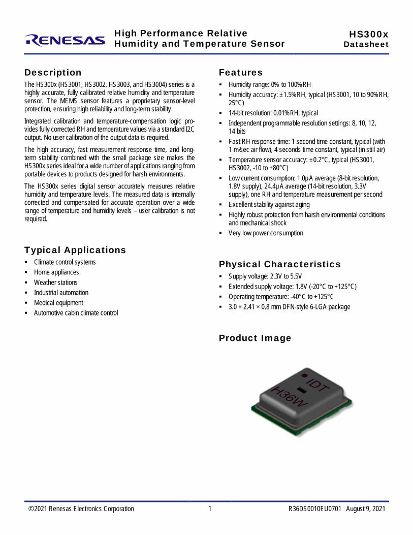
Description The HS300x (HS3001, HS3002, HS3003, and HS3004) series is a highly accurate, fully calibrated relative humidity and temperature sensor. The MEMS sensor features a proprietary sensor-level protection, ensuring high reliability and long-term stability. Integrated calibration and temperature-compensation logic pro-vides fully corrected RH and temperature values via a standard I2C output. No user calibration of the output data is required. The high accuracy, fast measurement response time, and long-term stability combined with the small package size makes the HS300x series ideal for a wide number of applications ranging from portable devices to products designed for harsh environments. The HS300x series digital sensor accurately measures relative humidity and temperature levels. The measured data is internally corrected and compensated for accurate operation over a wide range of temperature and humidity levels – user calibration is not required.
Typical Applications Climate control systems Home appliances Weather stations Industrial automation Medical equipment Automotive cabin climate control
Features Humidity range: 0% to 100%RH Humidity accuracy: ±1.5%RH, typical (HS3001, 10 to 90%RH,
25°C) 14-bit resolution: 0.01%RH, typical Independent programmable resolution settings: 8, 10, 12,
14 bits Fast RH response time: 1 second time constant, typical (with
1 m/sec air flow), 4 seconds time constant, typical (in still air) Temperature sensor accuracy: ±0.2°C, typical (HS3001,
HS3002, -10 to +80°C) Low current consumption: 1.0µA average (8-bit resolution,
1.8V supply), 24.4µA average (14-bit resolution, 3.3V supply), one RH and temperature measurement per second
Excellent stability against aging Highly robust protection from harsh environmental conditions
and mechanical shock Very low power consumption
Physical Characteristics Supply voltage: 2.3V to 5.5V Extended supply voltage: 1.8V (-20°C to +125°C) Operating temperature: -40°C to +125°C 3.0 × 2.41 × 0.8 mm DFN-style 6-LGA package
Product Image

HS300x Datasheet
© 2021 Renesas Electronics Corporation 2 R36DS0010EU0701 August 9, 2021
Contents 1. Pin Assignments ...........................................................................................................................................................................................4 2. Pin Descriptions ............................................................................................................................................................................................4 3. Absolute Maximum Ratings ..........................................................................................................................................................................5 4. Recommended Operating Conditions...........................................................................................................................................................5 5. Humidity and Temperature Sensor Performance .........................................................................................................................................6
5.1 Humidity Sensor Specification .............................................................................................................................................................6 5.2 Temperature Sensor Specification ......................................................................................................................................................7 5.3 Sleep Current ......................................................................................................................................................................................7 5.4 Humidity Sensor Accuracy Graphs ......................................................................................................................................................8 5.5 Temperature Sensor Accuracy Graphs ...............................................................................................................................................9
6. Sensor Interface .........................................................................................................................................................................................10 6.1 I2C Features and Timing ...................................................................................................................................................................10 6.2 Sensor Slave Address .......................................................................................................................................................................10 6.3 I2C Communication ...........................................................................................................................................................................11 6.4 Measurement Mode ...........................................................................................................................................................................11 6.5 Measurement Requests (MR) ...........................................................................................................................................................11 6.6 Data Fetch (DF) .................................................................................................................................................................................12 6.7 Status Bits .........................................................................................................................................................................................13 6.8 Accessing the Non-volatile Memory ..................................................................................................................................................13 6.9 Setting the Measurement Resolution.................................................................................................................................................14 6.10 Reading the HS300x ID Number .......................................................................................................................................................14
7. Calculating Humidity and Temperature Output...........................................................................................................................................15 8. Application Circuit .......................................................................................................................................................................................15 9. Package Outline Drawings .........................................................................................................................................................................16 10. Soldering Information .................................................................................................................................................................................16 11. PCB Layout Guide ......................................................................................................................................................................................17 12. Storage and Handling .................................................................................................................................................................................17 13. Quality and Reliability .................................................................................................................................................................................17 14. Ordering Information ...................................................................................................................................................................................18 15. Revision History ..........................................................................................................................................................................................18
List of Figures Figure 1. Pin Assignments for 3mm × 2.41mm 6-LGA Package (Top View) .....................................................................................................4 Figure 2. Sleep Current Variation over Temperature, VDD at 3.3V......................................................................................................................7 Figure 3. HS3001 RH Accuracy Tolerance at 25°C ...........................................................................................................................................8 Figure 4. HS3001 RH Accuracy over Temperature ............................................................................................................................................8 Figure 5. HS3002 RH Accuracy Tolerance at 25°C ...........................................................................................................................................8
HS300x Datasheet
© 2021 Renesas Electronics Corporation 3 R36DS0010EU0701 August 9, 2021
Figure 6. HS3002 RH Accuracy over Temperature ............................................................................................................................................8 Figure 7. HS3003 RH Accuracy Tolerance at 25°C ...........................................................................................................................................8 Figure 8. HS3003 RH Accuracy over Temperature ............................................................................................................................................8 Figure 9. HS3004 RH Accuracy Tolerance at 25°C ...........................................................................................................................................9 Figure 10. HS3004 RH Accuracy over Temperature .............................................................................................................................................9 Figure 11. HS3001/HS3002 Temperature Sensor Accuracy Tolerance ...............................................................................................................9 Figure 12. HS3003 Temperature Sensor Accuracy Tolerance .............................................................................................................................9 Figure 13. HS3004 Temperature Sensor Accuracy Tolerance .............................................................................................................................9 Figure 14. Timing Diagram .................................................................................................................................................................................10 Figure 15. START and STOP Condition Waveform............................................................................................................................................11 Figure 16. Measurement Request ......................................................................................................................................................................11 Figure 17. Data Fetch .........................................................................................................................................................................................12 Figure 18. Sequence of Commands to Enter Programming Mode .....................................................................................................................13 Figure 19. Sequence of Commands to Change the Relative Humidity Resolution..............................................................................................14 Figure 20. HS300x Application Circuit (Top View) ..............................................................................................................................................15 Figure 21. Recommended Soldering Profile .......................................................................................................................................................16 Figure 22. Milled PCB Openings for Thermal Isolation .......................................................................................................................................17
List of Tables Table 1. Pin Descriptions ...................................................................................................................................................................................4 Table 2. Absolute Maximum Ratings .................................................................................................................................................................5 Table 3. Operating Conditions ...........................................................................................................................................................................5 Table 4. Humidity Sensor Specification, TA = +25°C, VDD = 2.3V to 5.5V .........................................................................................................6 Table 5. Temperature Sensor Specification, TA = +25°C, VDD = 2.3V to 5.5V ..................................................................................................7 Table 6. I2C Timing Parameters ......................................................................................................................................................................10 Table 7. Status Bits .........................................................................................................................................................................................13 Table 8. Non-volatile Memory Registers .........................................................................................................................................................13 Table 9. Register Values for Different Resolution Settings..............................................................................................................................14

HS300x Datasheet
© 2021 Renesas Electronics Corporation 4 R36DS0010EU0701 August 9, 2021
1. Pin Assignments
Figure 1. Pin Assignments for 3mm × 2.41mm 6-LGA Package (Top View)
1
54
3 2
6
VC SDA SCL
VDD NC VSS
Pin 1 marker on bottom side
2. Pin Descriptions
Table 1. Pin Descriptions
Pin Number Name Type Description
1 SCL In/out Serial clock
2 SDA In/out Serial data
3 VC Connect a 0.1µF decoupling capacitor from VC to ground
4 VDD In Supply voltage
5 NC Do not connect
6 VSS In Ground
[a] “NC” stands for not connected / no connection required / not bonded.

HS300x Datasheet
© 2021 Renesas Electronics Corporation 5 R36DS0010EU0701 August 9, 2021
3. Absolute Maximum Ratings The absolute maximum ratings are stress ratings only. Stresses greater than those listed below can cause permanent damage to the device. Functional operation of the HS300x at absolute maximum ratings is not implied. Exposure to absolute maximum rating conditions might affect device reliability.
Table 2. Absolute Maximum Ratings
Symbol Parameter Conditions Minimum Maximum Unit
Analog Supply Voltage -0.3 6.0 V
Storage Temperature Range -55 125 °C
4. Recommended Operating Conditions Important note: The HS300x series sensors are optimized to perform best in the more common temperature and humidity ranges of 10°C to 50°C and 20% RH to 80% RH, respectively. If operated outside of these conditions for extended periods, especially at high humidity levels, the sensors may exhibit an offset. In most cases, this offset is temporary and will gradually disappear once the sensor is returned to normal temperature and humidity conditions. The amount of the shift and the duration of the offset vary depending on the duration of exposure and the severity of the relative humidity and temperature conditions. The time needed for the offset to disappear can also be decreased by using the procedures described in sections 10 and 12.
Table 3. Operating Conditions
Parameter Condition Minimum Typical Maximum Unit
Operating Supply Voltage 3.3 5.5 V
Extended Operating Supply Voltage Operating temperature from -20 to 125°C 1.8 5.5 V
Operating Humidity Range 0 100 %RH
Operating Temperature Sensor Range -40 125 °C
Sleep Current Sleep Mode
-40 to 85°C 0.6 1 µA
-40 to 125°C 1 3
Average Current [a] One RH + temperature measurement/second
8-bit resolution 1.0 1.5 1.7
µA 10-bit resolution 2.0 2.6 2.8
12-bit resolution 5.5 7.0 7.1
14-bit resolution 20.1 24.4 24.4
Measurement Time
Wake-up 0.10
ms Humidity or temperature including the digital compensation
8-bit resolution 0.55
10-bit resolution 1.31
12-bit resolution 4.50
14-bit resolution 16.90
[a] Minimum, typical and maximum average currents are given at 1.8V, 3.3V and 5.5V VDD respectively.

HS300x Datasheet
© 2021 Renesas Electronics Corporation 6 R36DS0010EU0701 August 9, 2021
5. Humidity and Temperature Sensor Performance
5.1 Humidity Sensor Specification
Table 4. Humidity Sensor Specification, TA = +25°C, VDD = 2.3V to 5.5V
Parameter Condition Minimum Typical Maximum Unit
Operating Range 0 100 %RH
Accuracy [a]
HS3001 10% to 90%RH
±1.5 ±1.8
%RH HS3002 ±1.8 ±2.0
HS3003 20% to 80%RH
±2.5 ±3.5
HS3004 ±3.5 ±4.5
Resolution 8-bit 0.7 1.0
%RH 14- bit 0.01 0.015
Hysteresis ±1.0 %RH
Noise in Humidity (RMS) 14-bit 0.014 %RH
Non-Linearity from Response Curve
HS3001 10% to 90%RH
±0.15 ±0.25 %RH HS3002
HS3003 20% to 80%RH
HS3004
Long-Term Stability ±0.1 ±0.25 %RH/Yr
Response Time Constant [b] (τH) 20% to 80% RH, 1 meter/sec air flow
1 sec
20% to 80% RH Still Air 3.0 4.0 6.0
[a] Monotonic increases from 10 to 90%RH after sensor has been stabilized at 50%RH. [b] Initial value to 63% of total variation.

HS300x Datasheet
© 2021 Renesas Electronics Corporation 7 R36DS0010EU0701 August 9, 2021
5.2 Temperature Sensor Specification
Table 5. Temperature Sensor Specification, TA = +25°C, VDD = 2.3V to 5.5V
Parameter Condition Minimum Typical Maximum Unit
Range -40 125 °C
Accuracy
HS3001 -10°C to 80°C ±0.2 ±0.3
°C HS3002
HS3003 0°C to 70°C
±0.25 ±0.35
HS3004 ±0.3 ±0.5
Resolution 8- bit 0.6 0.9 1.5
°C 14-bit 0.01 0.015 0.025
Response Time Constant [a] (τT) 2..0 Sec.
Long-Term Stability 0.02 °C/Yr
Supply Voltage Dependency [b] VDD ≥ 2.8V 0.03 0.1 °C/V
1.8V < VDD < 2.8V 1.25 2.25 °C/V
[a] Response time depends on system thermal mass and air flow. [b] Temperature accuracy can be optimized for specified supply voltages upon request.
5.3 Sleep Current The sleep current of the HS300x series depends on the operating temperature, as shown in the following figure. Note that there is no significant dependence of the sleep current on the supply voltage.
Figure 2. Sleep Current Variation over Temperature, VDD at 3.3V

HS300x Datasheet
© 2021 Renesas Electronics Corporation 8 R36DS0010EU0701 August 9, 2021
5.4 Humidity Sensor Accuracy Graphs The typical and maximum relative humidity sensor accuracy tolerances are shown in the following figures.
Figure 3. HS3001 RH Accuracy Tolerance at 25°C
Figure 4. HS3001 RH Accuracy over Temperature
Figure 5. HS3002 RH Accuracy Tolerance at 25°C
Figure 6. HS3002 RH Accuracy over Temperature
Figure 7. HS3003 RH Accuracy Tolerance at 25°C
Figure 8. HS3003 RH Accuracy over Temperature
90
70
50
30
100 10 20 30 40 50 60 70
Temperature (°C)
Rel.
Hum
idity
(%RH
)
±2.0
±2.5 ±3.0
±2.0
±1.5±2.0
±2.0
90
70
50
30
100 10 20 30 40 50 60 70
Temperature (°C)
Rel.
Hum
idity
(%RH
)
±2.5 ±3.0
±2.5
±1.8±2.5
HS300x Datasheet
© 2021 Renesas Electronics Corporation 9 R36DS0010EU0701 August 9, 2021
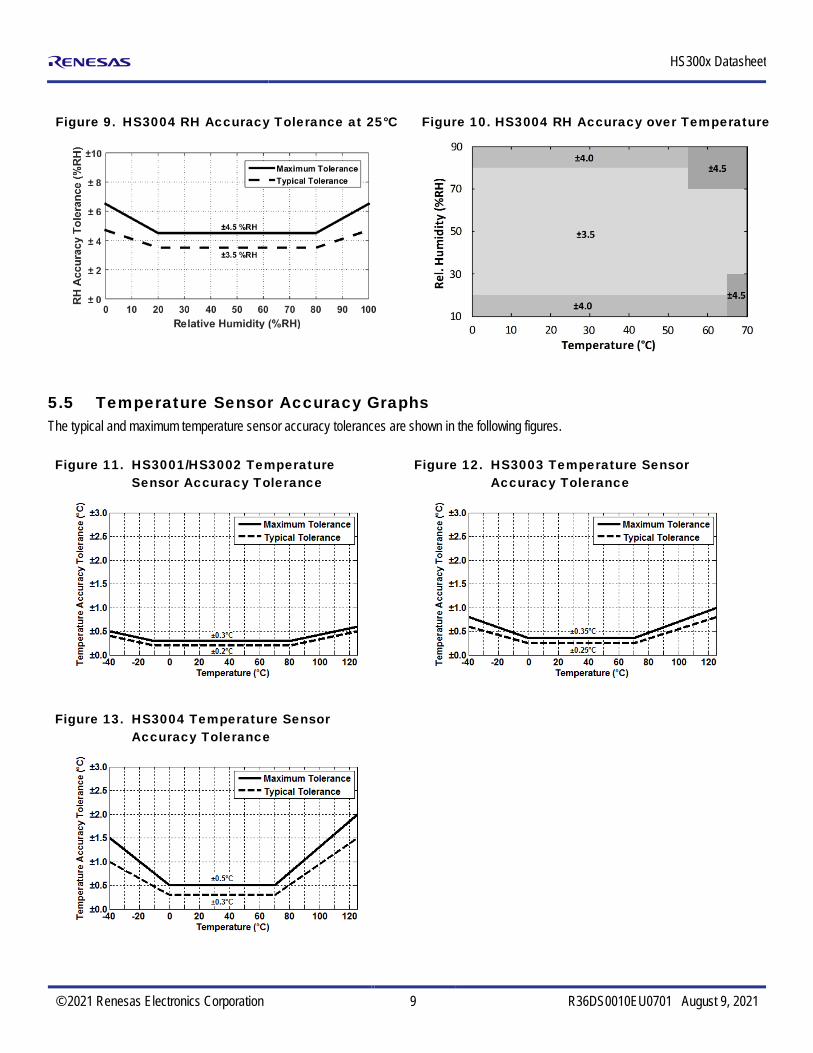
Figure 9. HS3004 RH Accuracy Tolerance at 25°C
Figure 10. HS3004 RH Accuracy over Temperature
5.5 Temperature Sensor Accuracy Graphs The typical and maximum temperature sensor accuracy tolerances are shown in the following figures.
Figure 11. HS3001/HS3002 Temperature Sensor Accuracy Tolerance
Figure 12. HS3003 Temperature Sensor Accuracy Tolerance
Figure 13. HS3004 Temperature Sensor Accuracy Tolerance

HS300x Datasheet
© 2021 Renesas Electronics Corporation 10 R36DS0010EU0701 August 9, 2021
6. Sensor Interface The HS300x series sensor uses a digital I2C-compatible communication protocol. To accommodate multiple devices, the protocol uses two bi-directional open-drain lines: the Serial Data Line (SDA) and the Serial Clock Line (SCL). Pull-up resistors to VDD are required. Several slave devices can share the bus; however only one master device can be present on the line.
6.1 I2C Features and Timing The HS300x series sensor operates as a slave device on the I2C bus with support for 100kHz and 400kHz bit rates. Each transmission is initiated when the master sends a 0 START bit (S), and the transmission is terminated when the master sends a 1 STOP bit (P). These bits are only transmitted while the SCL line is HIGH.
Figure 14. Timing Diagram
tBUStHDSTAtSUDATtLOW
SDA
SCL
tHDSTA tSUSTOtSUSTAtHIGHtHDDAT
Table 6. I2C Timing Parameters
Parameter Symbol Minimum Typical Maximum Unit
SCL Clock Frequency[a] fSCL 20 400 kHz
START Condition Hold Time Relative to SCL Edge tHDSTA 0.1 µs
Minimum SCL Clock LOW Width[b] tLOW 0.6 µs
Minimum SCL Clock HIGH Width[b] tHIGH 0.6 µs
START Condition Setup Time Relative to SCL Edge tSUSTA 0.1 µs
Data Hold Time on SDA Relative to SCL Edge tHDDAT 0 0.5 µs
Data Setup Time on SDA Relative to SCL Edge tSUDAT 0.1 µs
STOP Condition Setup Time on SCL tSUSTO 0.1 µs
Bus Free Time Between STOP Condition and START Condition tBUS 1 µs
[a] The minimum frequency of 20kHz applies to test only; no minimum under normal operations. [b] Combined LOW and HIGH widths must equal or exceed the minimum SCL period.
6.2 Sensor Slave Address The HS300x series default I2C address is 44HEX. The device will respond only to this 7-bit address. See section 6.3 for further information. Custom I2C address can be provided upon request.

HS300x Datasheet
© 2021 Renesas Electronics Corporation 11 R36DS0010EU0701 August 9, 2021
6.3 I2C Communication The sensor transmission is initiated when the master sends a 0 START bit (S). The transmission is terminated when the master sends a 1 STOP bit (P). These bits are only transmitted while the SCL line is HIGH (see Figure 155 for waveforms). Once the START condition has been set, the SCL line is toggled at the prescribed data rate, clocking subsequent data transfers. Data on the SDA line is always sampled on the rising edge of the SCL line and must remain stable while SCL is HIGH to prevent false START or STOP conditions.
Figure 15. START and STOP Condition Waveform
START Condition STOP Condition
STOP
SDA
SCL
SDA
SCLSTART
After the START bit, the master device sends the 7-bit slave address (see section 6.2) to the HS300x, followed by the read/write bit, which indicates the transfer direction of any subsequent data. This bit is set to 1 to indicate a read from slave to master or set to 0 to indicate a write from master to slave. All transfers consist of 8 bits and a response bit: 0 for Acknowledge (ACK) or 1 for Not Acknowledge (NACK). After the ACK is received, another data byte can be transferred or the communication can be stopped with a STOP bit.
6.4 Measurement Mode The HS300x is factory-programmed to operate in Sleep Mode. In Sleep Mode, the sensor waits for commands from the master before taking measurements. The digital core only performs conversions when it receives a Measurement Request command (MR); otherwise, it is always powered down.
6.5 Measurement Requests (MR) The MR command is required to wake up the HS300x from its Sleep Mode. Initiate the Measurement Request by sending the 7-bit slave address followed by an eighth bit = 0 (WRITE). A measurement cycle consists of a humidity and temperature conversion followed by the digital signal processor (DSP) correction calculations. At the end of a measurement cycle, the digital output register will be updated before powering down. The output is always scaled to 14 bits. The order of the bits is big-endian.
Figure 16. Measurement Request
S
Device Slave Address [6:0]
Slave Address Bit (MSB first)
Start Condition Stop Condition Acknowledge (ACK) Read/Write (Example: Write = 0) S S W
Wait for Slave ACK
1S 0 0 10 0 W(0)
0 A
A

HS300x Datasheet
© 2021 Renesas Electronics Corporation 12 R36DS0010EU0701 August 9, 2021
6.6 Data Fetch (DF) At the end of a measurement cycle, valid data can be fetched. The status bits of the DF results can be used to detect if the data is valid or stale (see section 6.7); otherwise, wait for the measurements to complete before performing the DF. The DF command starts with the 7-bit slave address followed by an eighth bit = 1 (READ). The HS300x as a slave sends an acknowledge (ACK) indicating success. The number of data bytes returned by the HS300x is determined by when the master sends the NACK and STOP condition. The full 14 bits of the humidity data are fetched in the first two bytes. The two MSBs of the first byte are the status bits. The 14 bits of temperature data follow the humidity data. The last two bits (LSBs) of the fourth data byte are undetermined and should be masked off. In the event that the temperature data is not needed, the read can be terminated by sending a NACK after the second byte. Alternatively, if only 8-bit resolution is desired for the temperature output, the read can be terminated after the 3rd byte by issuing a NACK followed by a stop bit. The measurement time depends on the configured sensor resolution. The following table lists examples when the resolutions for the relative humidity and temperature measurements are the same. For different relative humidity and temperature resolution settings, the measurement times in 3 should be used, along with the 0.1 ms wake-up time. For example, an 8-bit relative humidity measurement and a 12-bit temperature measurement results in a total measurement time of:
0.1 ms + 0.55 ms + 4.5 ms = 5.15 ms. RH+T measurement times (including wake-up time) at different resolution settings.
Resolution1
(bits) Measurement
time (ms)
8 1.20 10 2.72 12 9.10 14 33.90
1Same resolutions are assumed for both relative humidity and temperature.
Figure 17. Data Fetch
Device Slave Address [6:0] Humidity Data [13:8] Humidity Data [7:0]
Humidity Data [13:8] Humidity Data [7:0] Temp. Data [15:8]
Slave Address Bit (MSB first) Command or Data Bit (Example: Bit 2) Status Bit
Start Condition Stop Condition Acknowledge (ACK) Not Acknowledge Read/Write (NACK) (Read = 1)S S RN
Wait forSlave ACK Master ACK Master ACK Master NACK
14 13 1112 10 89 A 6 57 34 2 N1 0 S1S 0 0 10 0 R(1)
0 A 15
1S 0 1 0 R(1)
0 A 14 1315 1112 10 89 A 6 57 34 2 A1 0 14 1315 1112 10 A9 800
Device Slave Address [6:0]
A
2
Temp. Data [7:2]
6 57 34 2 SN1 0
Mask [1:0]
HS300x Datasheet
© 2021 Renesas Electronics Corporation 13 R36DS0010EU0701 August 9, 2021
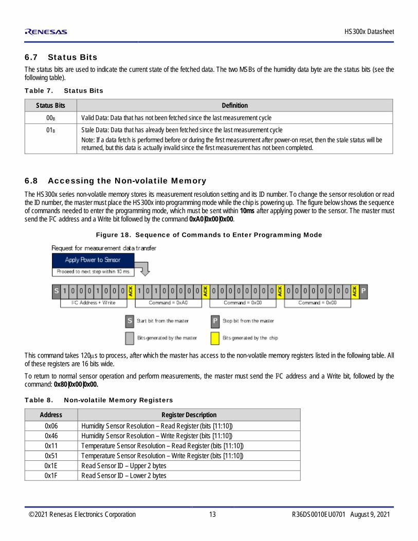
6.7 Status Bits The status bits are used to indicate the current state of the fetched data. The two MSBs of the humidity data byte are the status bits (see the following table).
Table 7. Status Bits
Status Bits Definition
00B Valid Data: Data that has not been fetched since the last measurement cycle
01B Stale Data: Data that has already been fetched since the last measurement cycle Note: If a data fetch is performed before or during the first measurement after power-on reset, then the stale status will be returned, but this data is actually invalid since the first measurement has not been completed.
6.8 Accessing the Non-volatile Memory The HS300x series non-volatile memory stores its measurement resolution setting and its ID number. To change the sensor resolution or read the ID number, the master must place the HS300x into programming mode while the chip is powering up. The figure below shows the sequence of commands needed to enter the programming mode, which must be sent within 10ms after applying power to the sensor. The master must send the I2C address and a Write bit followed by the command 0xA0|0x00|0x00.
Figure 18. Sequence of Commands to Enter Programming Mode
This command takes 120µs to process, after which the master has access to the non-volatile memory registers listed in the following table. All of these registers are 16 bits wide. To return to normal sensor operation and perform measurements, the master must send the I2C address and a Write bit, followed by the command: 0x80|0x00|0x00.
Table 8. Non-volatile Memory Registers
Address Register Description 0x06 Humidity Sensor Resolution – Read Register (bits [11:10]) 0x46 Humidity Sensor Resolution – Write Register (bits [11:10]) 0x11 Temperature Sensor Resolution – Read Register (bits [11:10]) 0x51 Temperature Sensor Resolution – Write Register (bits [11:10]) 0x1E Read Sensor ID – Upper 2 bytes 0x1F Read Sensor ID – Lower 2 bytes

HS300x Datasheet
© 2021 Renesas Electronics Corporation 14 R36DS0010EU0701 August 9, 2021
6.9 Setting the Measurement Resolution The HS300x series relative humidity and temperature measurement resolutions can be set independently to 8, 10, 12, or 14-bits by writing to the non-volatile memory, and are initially set to 14-bits by default. The procedure to set the humidity sensor resolution is illustrated in the following figure. The relative humidity and temperature resolution can be read in registers 0x06 and 0x11, respectively, or written in registers 0x46 or 0x51. The resolution information is stored in bits [11:10] of these registers, as listed in the Table 10. All of the other bits in these registers must be left unchanged. As such, before writing new resolution settings, the contents of the read registers must be read, and only bits [11:10] can be changed in the write registers. Once bits [11:10] are changed to set the desired resolution, the entire register must be written back to the HS300x sensor.
Figure 19. Sequence of Commands to Change the Relative Humidity Resolution
Table 9. Register Values for Different Resolution Settings
Resolution register bits [11:10]
Resolution (bits)
00B 8 01B 10 10B 12 11B 14
The sensor non-volatile memory requires 120µs to load the data into the registers after step 1, and requires 14ms to write the data after step 4. Failure to comply with these processing times may result in data corruption and introduce errors in sensor measurements. The procedure to change the temperature sensor resolution is the same as that depicted in Figure 19, except the register address in Step 1 must be set to 0x11 and the register address in Step 4 will be 0x51.
6.10 Reading the HS300x ID Number The sensor ID is a 32-bit number, and can be read in a similar fashion as illustrated in steps 1 and 2 of Figure 19, using the appropriate register address values. The ID number is stored in two registers, with the upper and lower 16 bits stored in register addresses 0x1E and 0x1F, respectively.

HS300x Datasheet
© 2021 Renesas Electronics Corporation 15 R36DS0010EU0701 August 9, 2021
7. Calculating Humidity and Temperature Output The entire output of the HS300x is 4 bytes. The relative humidity (in percent) and the temperature (in degrees Celsius) are calculated with Equation 1 and Equation 2, respectively.
14[13 0][%RH] 100
2 1Humidity :Humidity = ∗
− Equation 1
o14
[15 2] [ C] 165 402 1
Temperature :Temperature = ∗ − −
Equation 2
8. Application Circuit
Figure 20. HS300x Application Circuit (Top View)
0.1µF
VDD
RP = Pull-up resistor (2.2kΩ typical)
0.1µF
1 SCL
VDD 43 VC
2 SDA NC 5
VSS 6
RP RP

HS300x Datasheet
© 2021 Renesas Electronics Corporation 16 R36DS0010EU0701 August 9, 2021
9. Package Outline Drawings The package outline drawings are located at the end of this document and are accessible from the Renesas website. The package information is the most current data available and is subject to change without revision of this document.
10. Soldering Information This section discusses soldering considerations for the HS300x. When a relative humidity sensor is exposed to the high heat associated with the soldering process, the sensor element tends to dry out. To avoid an offset in the relative humidity readings, the sensor element must be rehydrated after the soldering process. Care must also be taken when selecting the temperatures and durations involved in the soldering process to avoid irreversibly damaging the sensor element. The recommended soldering profile for a lead-free (RoHS-compliant) process is shown below.
Figure 21. Recommended Soldering Profile
It is important to ensure this temperature profile is measured at the sensor itself. Measuring the profile at a larger component with a higher thermal mass means the temperature at the small sensor will be higher than expected. For manual soldering, the contact time must be limited to 5 seconds with a maximum iron temperature of 350°C. In either case, a board wash after soldering is not recommended. Therefore, if a solder paste is used, it is strongly recommended that a “no-clean” solder paste is used to avoid the need to wash the PCB. After soldering, the recommended rehydration conditions are either: A relative humidity of 75% RH at room temperature for at least 12 hours A relative humidity of 40% to 50% RH at room temperature for 3 to 5 days Otherwise, in the relative humidity readings, there might be an initial offset, which will slowly disappear as the sensor is exposed to ambient conditions.

HS300x Datasheet
© 2021 Renesas Electronics Corporation 17 R36DS0010EU0701 August 9, 2021
11. PCB Layout Guide When designing the PCB, undesired heat transfer paths to the HS300x series must be minimized. Excessive heat from other components on the PCB will result in inaccurate temperature and relative humidity measurements. As such, solid metal planes for power supplies should be avoided in the vicinity of the sensor since these will act as thermal conductors. To further reduce the heat transfer from other components on the board, openings can be milled into the PCB as shown in Figure 21.
Figure 22. Milled PCB Openings for Thermal Isolation
12. Storage and Handling Recommendation: Once the sensors are removed from their original packaging, store them in metal-in antistatic bags. Avoid using polyethylene antistatic bags as they may affect sensor accuracy. The nominal storage conditions are 10 to 50°C and humidity levels within 20% to 60%RH. If stored outside of these conditions for extended periods of time, the sensor readings may exhibit an offset. The sensor can be reconditioned and brought back to its calibration state by applying the following procedure: 1. Bake at a temperature of 100°C with a humidity < 10%RH for 10 to 12 hours. 2. Rehydrate the sensor at a humidity of 75%RH and a temperature between 20 to 30°C for 12 to 14 hours.
13. Quality and Reliability The HS300x series is available as a qualified product for consumer and industrial market applications. All data specified parameters are guaranteed if not stated otherwise.
HS300x Datasheet
© 2021 Renesas Electronics Corporation 18 R36DS0010EU0701 August 9, 2021
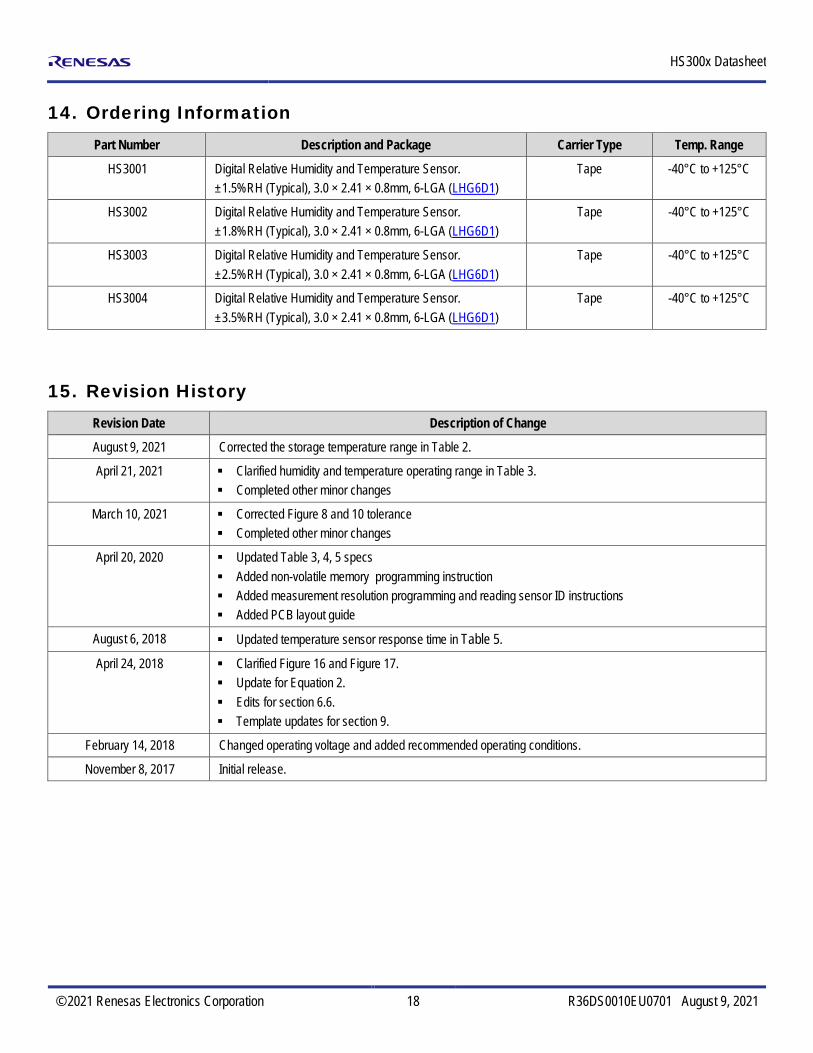
14. Ordering Information Part Number Description and Package Carrier Type Temp. Range
HS3001 Digital Relative Humidity and Temperature Sensor. ±1.5%RH (Typical), 3.0 × 2.41 × 0.8mm, 6-LGA (LHG6D1)
Tape -40°C to +125°C
HS3002 Digital Relative Humidity and Temperature Sensor. ±1.8%RH (Typical), 3.0 × 2.41 × 0.8mm, 6-LGA (LHG6D1)
Tape -40°C to +125°C
HS3003 Digital Relative Humidity and Temperature Sensor. ±2.5%RH (Typical), 3.0 × 2.41 × 0.8mm, 6-LGA (LHG6D1)
Tape -40°C to +125°C
HS3004 Digital Relative Humidity and Temperature Sensor. ±3.5%RH (Typical), 3.0 × 2.41 × 0.8mm, 6-LGA (LHG6D1)
Tape -40°C to +125°C
15. Revision History Revision Date Description of Change
August 9, 2021 Corrected the storage temperature range in Table 2.
April 21, 2021 Clarified humidity and temperature operating range in Table 3. Completed other minor changes
March 10, 2021 Corrected Figure 8 and 10 tolerance Completed other minor changes
April 20, 2020 Updated Table 3, 4, 5 specs Added non-volatile memory programming instruction Added measurement resolution programming and reading sensor ID instructions Added PCB layout guide
August 6, 2018 Updated temperature sensor response time in Table 5.
April 24, 2018 Clarified Figure 16 and Figure 17. Update for Equation 2. Edits for section 6.6. Template updates for section 9.
February 14, 2018 Changed operating voltage and added recommended operating conditions.
November 8, 2017 Initial release.

1 2 3
456
© Integrated Device Technology, Inc.
6-LGA Package Outline Drawing
3.0 x 2.41 x 0.8 mm Body, 1.0mm PitchLHG6D1, PSC-4719-01, Rev 01, Page 1

1 2 3
456
© Integrated Device Technology, Inc.
6-LGA Package Outline Drawing
3.0 x 2.41 x 0.8 mm Body, 1.0mm PitchLHG6D1, PSC-4719-01, Rev 01, Page 2
Package Revision HistoryRev No.Date Created Description
Sept 25, 2017 Rev 00 Initial ReleaseJune 25, 2018 Rev 01 Revise Lead Length
Corporate HeadquartersTOYOSU FORESIA, 3-2-24 Toyosu,Koto-ku, Tokyo 135-0061, Japanwww.renesas.com
Contact InformationFor further information on a product, technology, the most up-to-date version of a document, or your nearest sales office, please visit:www.renesas.com/contact/
TrademarksRenesas and the Renesas logo are trademarks of Renesas Electronics Corporation. All trademarks and registered trademarks are the property of their respective owners.
IMPORTANT NOTICE AND DISCLAIMER
RENESAS ELECTRONICS CORPORATION AND ITS SUBSIDIARIES (“RENESAS”) PROVIDES TECHNICAL SPECIFICATIONS AND RELIABILITY DATA (INCLUDING DATASHEETS), DESIGN RESOURCES (INCLUDING REFERENCE DESIGNS), APPLICATION OR OTHER DESIGN ADVICE, WEB TOOLS, SAFETY INFORMATION, AND OTHER RESOURCES “AS IS” AND WITH ALL FAULTS, AND DISCLAIMS ALL WARRANTIES, EXPRESS OR IMPLIED, INCLUDING, WITHOUT LIMITATION, ANY IMPLIED WARRANTIES OF MERCHANTABILITY, FITNESS FOR A PARTICULAR PURPOSE, OR NON-INFRINGEMENT OF THIRD PARTY INTELLECTUAL PROPERTY RIGHTS.
These resources are intended for developers skilled in the art designing with Renesas products. You are solely responsible for (1) selecting the appropriate products for your application, (2) designing, validating, and testing your application, and (3) ensuring your application meets applicable standards, and any other safety, security, or other requirements. These resources are subject to change without notice. Renesas grants you permission to use these resources only for development of an application that uses Renesas products. Other reproduction or use of these resources is strictly prohibited. No license is granted to any other Renesas intellectual property or to any third party intellectual property. Renesas disclaims responsibility for, and you will fully indemnify Renesas and its representatives against, any claims, damages, costs, losses, or liabilities arising out of your use of these resources. Renesas' products are provided only subject to Renesas' Terms and Conditions of Sale or other applicable terms agreed to in writing. No use of any Renesas resources expands or otherwise alters any applicable warranties or warranty disclaimers for these products.
(Rev.1.0 Mar 2020)
© 2020 Renesas Electronics Corporation. All rights reserved.