high performance guided wave radar level...
TRANSCRIPT

SIL Certified Safety Manual for
Eclipse® Model 706-512X-XXX
High Performance Guided WaveRadar Level Transmitter
This manual complements and is intended to be used with theMagnetrol® Eclipse® Model 706 High Performance Guided WaveRadar Installation and Operating manual (Bulletin 57-606).
Safety Function
The HART® version of the Eclipse® Enhanced Model 706Guided Wave Radar (GWR) transmitter will measurelevel and transmit a signal proportional to that levelwithin the stated safety accuracy of ±2% of span (or themeasured error published in I/O Manual 57-606,whichever is greater). In addition, when continuous,automatic diagnostics detect that the transmitter cannotperform this function, the output will be driven to thecustomer-specified out-of-range signal (i.e., 3.6 mA or21 mA).
The Enhanced Model 706 is certified for use in lowdemand level measurement applications.
Application
The HART® version of the ECLIPSE Model 706Guided Wave Radar level transmitter can be applied inmost process or storage vessels, bridles, and bypasschambers up to the probe’s rated temperature and pres-sure. It can be used in liquids, slurries, or solids with adielectric constant in the range 1.4–100 to meet thesafety system requirements of IEC 61508 (Edition 2.0,2010) and IEC 61511-1.
Benefits
• SIL 3 systematic capability• Level protection to SIL 3 as certified by exida Certification per IEC 61508/IEC 61511-1.
• Probe designs to +850 °F (+454 °C), 6250 psig(430 bar) and full vacuum.
• Cryogenic applications to -320 °F (-190 °C).
• Intrinsically safe, Explosion-proof and Non-Incendive approvals.
• Quick connect/disconnect probe coupling.

57-657 SIL Certified Safety Manual for ECLIPSE Model 706
Table of Contents
Eclipse® Model 706 High Performance Guided Wave Radar Level TransmitterSIL Safety Manual for Eclipse® Model 706-512x-xxx
1.0 Introduction ...................................................................31.1 Product Description..................................................31.2 Theory of Operation.................................................31.3 Determining Safety Integrity Level (SIL) ..................3
2.0 Applicable Models ..........................................................43.0 Level Measuring System .................................................4
3.1 Miscellaneous Electrical Considerations ....................53.1.1 Pollution Degree 2 .........................................53.1.2 Electromagnetic Compatibility.......................5
4.0 Mean Time To Repair (MTTR).....................................55.0 Supplementary Documentation......................................56.0 General Instructions.......................................................5
6.1 Systematic Limitations ..............................................56.1.1 Application.....................................................56.1.2 Environmental................................................6
6.1.2.1 Operating ........................................66.1.2.2 Storage .............................................6
6.2 Installation ................................................................66.3 Skill Level of Personnel .............................................66.4 Necessary Tools .........................................................76.5 Configuration Information .......................................7
6.5.1 General...........................................................76.5.2 Configuration.................................................76.5.3 Write Protecting /Locking ..............................7
6.6 Site Acceptance Testing .............................................86.7 Recording Results......................................................86.8 Maintenance ..............................................................8
6.8.1 Diagnostics and Response Times ....................86.8.2 Troubleshooting .............................................8
7.0 Recurrent Function Tests ...............................................97.1 Proof Testing .............................................................9
7.1.1 Introduction...................................................97.1.2 Interval...........................................................97.1.3 Recording Results...........................................97.1.4 Suggested Proof Test.......................................9
8.0 Safety Requirements .....................................................118.1 System Safety Assumptions .....................................118.2 Safety Function Requirements.................................128.3 Safety User Programming and Configuration
Requirements ..........................................................129.0 Appendices ...................................................................13
9.1 SIL Certificate.........................................................139.2 FMEDA Report : exida Management Summary ......149.3 Specific Model 706 Values ......................................159.4 Report: Lifetime of Critical Components................15
357-657 SIL Certified Safety Manual for ECLIPSE Model 706
1.0 Introduction
1.1 Product Description
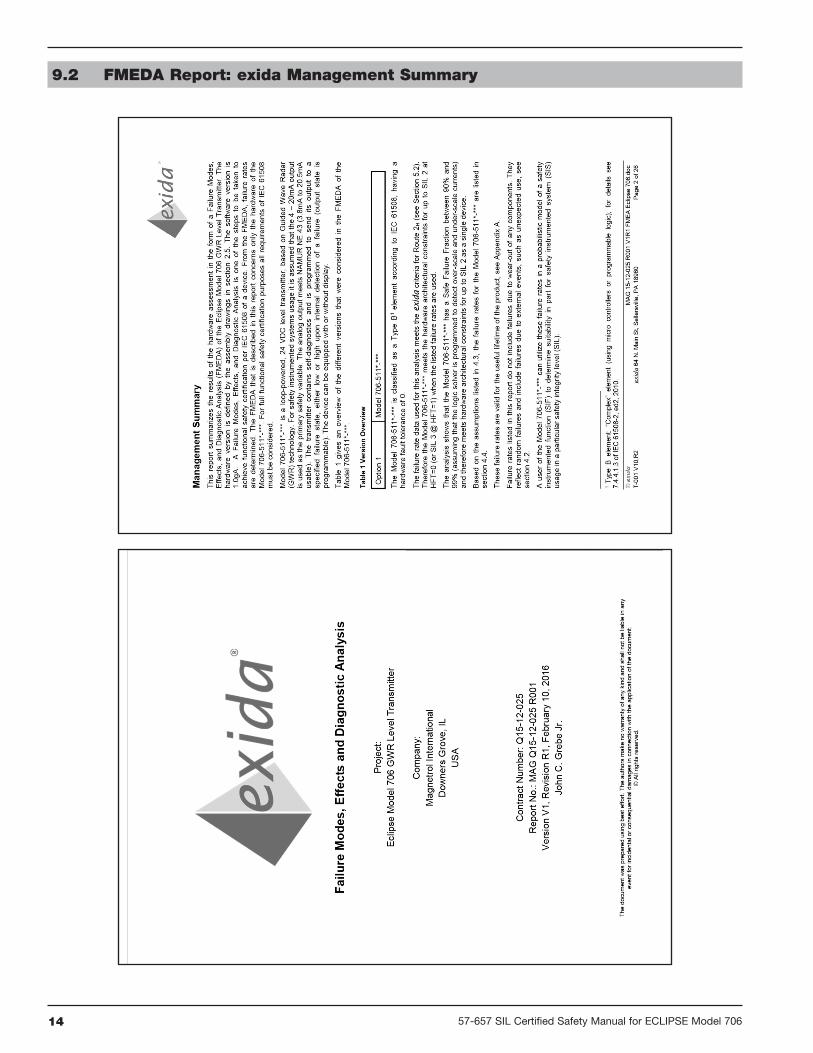
The ECLIPSE Model 706 High Performance Guided WaveRadar Level Transmitter is a two-wire, loop-powered24 VDC level transmitter based on Guided Wave Radar(GWR) technology.
NOTE: For Safety Instrumented Systems usage, it is assumed that the4–20 mA output is used as the safety variable.
The analog output from the Model 706 meets the NAMURNE 43 standard (3.8 mA to 20.5 mA usable). The transmittercontains self-diagnostics and is programmed to drive theoutput to a user-selected failure state, either low or high,upon internal detection of a diagnostic indicator. The devicecan be equipped with or without an optional non-interferinggraphic liquid crystal display (LCD).
Table 1 indicates the version of the ECLIPSE Model 706transmitter that has been certified for SIL 2/3 applications.
1.2 Theory of Operation
Guided Wave Radar is based upon the principle of TDR(Time Domain Reflectometry). TDR utilizes pulses of electro-magnetic energy transmitted down a wave guide (probe).When a pulse reaches a liquid surface that has a higherdielectric constant than the air (εr = 1) in which it is traveling,a portion of the pulse is reflected. The transit time of thepulse is then measured via ultra high-speed timing circuitrythat provides an accurate measure of the liquid level. Theamplitude of the reflection depends on the dielectric con-stant of the product. The higher the dielectric constant, thelarger the reflection.
1.3 Determining Safety Integrity Level (SIL)
Safety Instrumented System designers using the EnhancedECLIPSE Model 706 must verify their design per applicablestandards, including IEC 61511-1.
Three limits must be met to achieve a given SIL level:
1. The PFDAVG numbers for the entire Safety InstrumentedFunction (SIF) must be calculated. Table 2 shows the rela-tionship between the Safety Integrity Level (SIL) and theProbability of Failure on Demand Average (PFDAVG).
2. Architecture constraints must be met for each subsystem.Table 3 can be used to determine the achievable SIL as afunction of the Hardware Fault Tolerance (HFT) and the
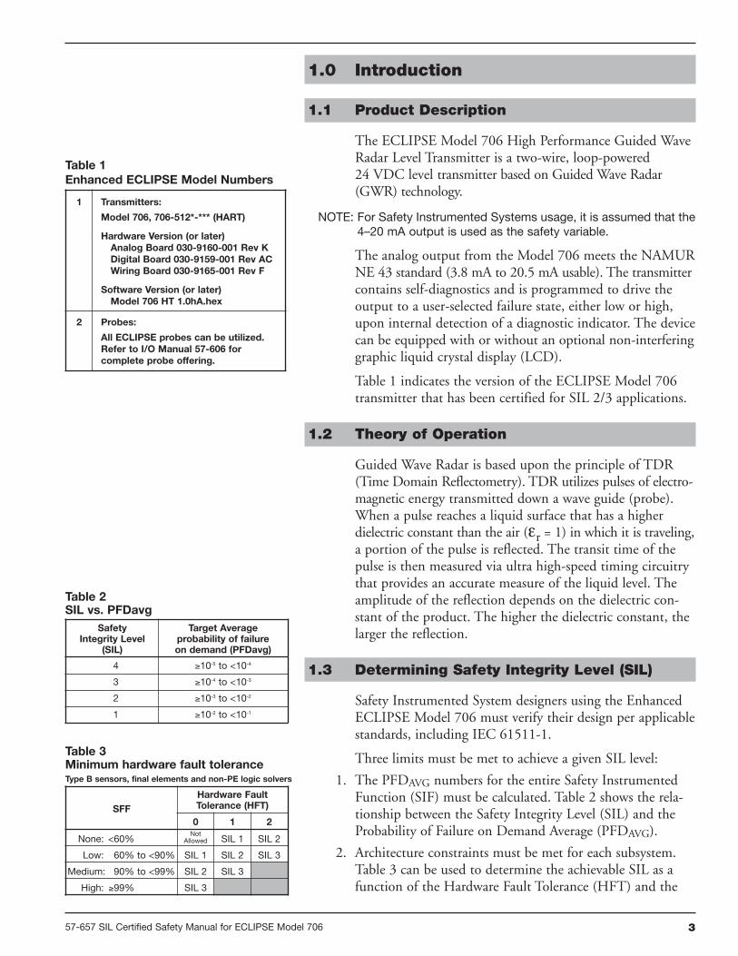
Table 3Minimum hardware fault toleranceType B sensors, final elements and non-PE logic solvers
SFF
Hardware FaultTolerance (HFT)
0 1 2
None: <60%Not
Allowed SIL 1 SIL 2
Low: 60% to <90% SIL 1 SIL 2 SIL 3
Medium: 90% to <99% SIL 2 SIL 3
High: ≥99% SIL 3
Table 2SIL vs. PFDavg
SafetyIntegrity Level
(SIL)
Target Averageprobability of failureon demand (PFDavg)
4 ≥10-5 to <10-4
3 ≥10-4 to <10-3
2 ≥10-3 to <10-2
1 ≥10-2 to <10-1
1 Transmitters:
Model 706, 706-512*-*** (HART)
Hardware Version (or later)Analog Board 030-9160-001 Rev KDigital Board 030-9159-001 Rev ACWiring Board 030-9165-001 Rev F
Software Version (or later)Model 706 HT 1.0hA.hex
2 Probes:
All ECLIPSE probes can be utilized.Refer to I/O Manual 57-606 forcomplete probe offering.
Table 1Enhanced ECLIPSE Model Numbers
4 57-657 SIL Certified Safety Manual for ECLIPSE Model 706
Safe Failure Fraction (SFF) for each subsystem in a safetysystem (Type B–complex components as per IEC 61508Part 2) of which the level transmitter is just one component.
3. All products chosen for use in the SIF must meet therequirements of IEC 61508 for the given SIL Capabilitylevel or be justified based on proven in use data collected foreach job.
The exSILentia tool from exida is recommended for designverification. This automatically checks all three limits anddisplays the results for any given design. The ECLIPSEModel 706 is in the exSILentia database. This tool containsall needed failure rate, failure mode, SIL Capability andcommon cause data as well as suggested proof test methods.
2.0 Applicable Models
This manual is only applicable to the HART versions ofthe ECLIPSE Model 706 transmitter shown in Table 1.
NOTE: Ensure that the Model 706 transmitter and probe are installedas a set matched by the Serial Number shown on the nameplates.
3.0 Level Measuring System
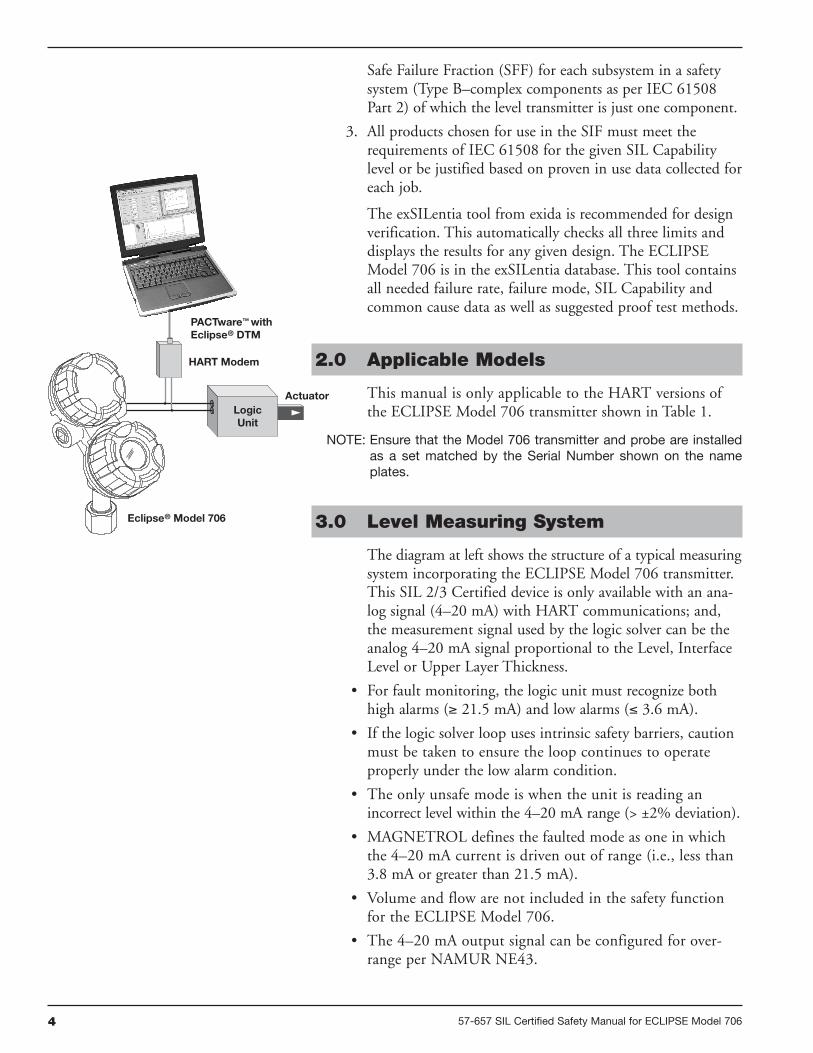
The diagram at left shows the structure of a typical measuringsystem incorporating the ECLIPSE Model 706 transmitter.This SIL 2/3 Certified device is only available with an ana-log signal (4–20 mA) with HART communications; and,the measurement signal used by the logic solver can be theanalog 4–20 mA signal proportional to the Level, InterfaceLevel or Upper Layer Thickness.
• For fault monitoring, the logic unit must recognize bothhigh alarms (≥ 21.5 mA) and low alarms (≤ 3.6 mA).
• If the logic solver loop uses intrinsic safety barriers, cautionmust be taken to ensure the loop continues to operateproperly under the low alarm condition.
• The only unsafe mode is when the unit is reading anincorrect level within the 4–20 mA range (> ±2% deviation).
• MAGNETROL defines the faulted mode as one in whichthe 4–20 mA current is driven out of range (i.e., less than3.8 mA or greater than 21.5 mA).
• Volume and flow are not included in the safety functionfor the ECLIPSE Model 706.
• The 4–20 mA output signal can be configured for over-range per NAMUR NE43.
Actuator
PACTware™ withEclipse® DTM
HART Modem
Eclipse® Model 706
LogicUnit
557-657 SIL Certified Safety Manual for ECLIPSE Model 706
3.1 Miscellaneous Electrical Considerations
Following are miscellaneous electrical issues to be consideredin a safety system.
3.1.1 Pollution Degree 2
The ECLIPSE Model 706 transmitter is designed for usein a Category II, Pollution Degree 2 installation, which isdefined by a nonconductive pollution of the sort whereoccasionally a temporary conductivity caused by condensationmust be expected.
This is the usual pollution degree used for equipment beingevaluated to IEC/EN 61010.
3.1.2 Electromagnetic Compatibility
The ECLIPSE Model 706 is designed to meet the require-ments of EN 61326 and NAMUR NE21.
4.0 Mean Time To Repair (MTTR)
SIL determinations are based on a number of factors includingthe Mean Time To Repair (MTTR). The analysis for theECLIPSE Model 706 is based on a MTTR of 24 hours.
5.0 Supplementary Documentation
• The ECLIPSE Model 706 Installation and OperatingManual 57-606 must be available to ensure properinstallation of the transmitter.
• The following Electronic Device Description File is requiredif HART is used:
• Manufacturer Code 0x56• Model 706 Device ID 0x56E0, device revision 1,
DD revision 2.
• For device installations in a classified area, the relevant safetyinstructions and electrical codes must be followed.
6.0 General Instructions
6.1 Systematic Limitations
The following instructions must be observed to avoidsystematic failures:
6.1.1 Application
Choosing the proper Guided Wave Radar (GWR) probe isthe most important decision in the application process.
6 57-657 SIL Certified Safety Manual for ECLIPSE Model 706
Coaxial, twin flexible cable, and single element (rod or cable)are the three basic configurations. As the probe configurationestablishes fundamental performance characteristics, theprobe for use with the ECLIPSE Model 706 transmittershould be selected as appropriate for the application.
The Model 706 is designed for use in many applications inprocess industries. Consult factory for assistance with probeoptions.
Careful selection of probe design and materials for a specificapplication will minimize media buildup on the probe.
Refer to Installation and Operating Manual 57-606 formore information.
6.1.2 Environmental
Refer to Installation and Operating Manual 57-606 forEnvironmental limitations.
6.1.2.1 Operating
The operating temperature range is -40 to +175 °F (-40 to+80 °C).
6.1.2.2 Storage
The device should be stored in its original shipping boxand not be subjected to temperatures outside the storagetemperature range of -50 to +185 °F (-46 to +85 °C).
6.2 Installation
Refer to the Model 706 Installation and Operating Manual57-606 manual for complete installation instructions.
• Contains information on the use, changing and resetting ofthe password-protection function.
• Provides menu selection items for configuration of thetransmitter as a level sensing device.
• Offers configuration recommendations.
• Input voltage and loop resistance must be within the safeoperating area of the device.
6.3 Skill Level of Personnel
Personnel following the procedures of this safety manualshould have technical expertise equal to or greater than thatof a qualified Instrument Technician.
757-657 SIL Certified Safety Manual for ECLIPSE Model 706
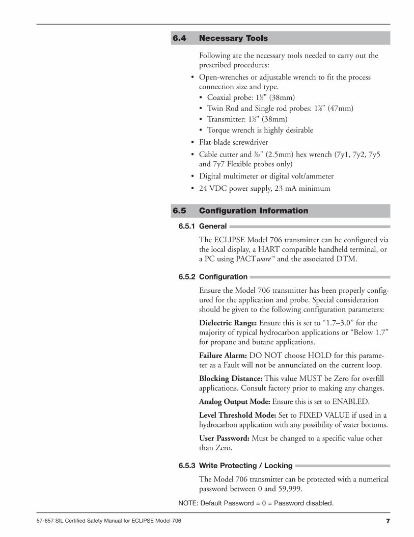
6.4 Necessary Tools
Following are the necessary tools needed to carry out theprescribed procedures:
• Open-wrenches or adjustable wrench to fit the processconnection size and type.• Coaxial probe: 11⁄2" (38mm)• Twin Rod and Single rod probes: 17⁄8" (47mm)• Transmitter: 11⁄2" (38mm)• Torque wrench is highly desirable
• Flat-blade screwdriver
• Cable cutter and 3⁄32" (2.5mm) hex wrench (7y1, 7y2, 7y5and 7y7 Flexible probes only)
• Digital multimeter or digital volt/ammeter
• 24 VDC power supply, 23 mA minimum
6.5 Configuration Information
6.5.1 General
The ECLIPSE Model 706 transmitter can be configured viathe local display, a HART compatible handheld terminal, ora PC using PACTware™ and the associated DTM.
6.5.2 Configuration
Ensure the Model 706 transmitter has been properly config-ured for the application and probe. Special considerationshould be given to the following configuration parameters:
Dielectric Range: Ensure this is set to “1.7–3.0” for themajority of typical hydrocarbon applications or “Below 1.7”for propane and butane applications.
Failure Alarm: DO NOT choose HOLD for this parame-ter as a Fault will not be annunciated on the current loop.
Blocking Distance: This value MUST be Zero for overfillapplications. Consult factory prior to making any changes.
Analog Output Mode: Ensure this is set to ENABLED.
Level Threshold Mode: Set to FIXED VALUE if used in ahydrocarbon application with any possibility of water bottoms.
User Password: Must be changed to a specific value otherthan Zero.
6.5.3 Write Protecting / Locking
The Model 706 transmitter can be protected with a numericalpassword between 0 and 59,999.
NOTE: Default Password = 0 = Password disabled.

Refer to the Model 706 Installation and Operating ManualBulletin 57-606 for additional information on passwordprotection.
For an SIS system, it is required that, after configuration ofthe system is complete, a password is utilized to preventinadvertent changes to the device.
6.6 Site Acceptance Testing
To ensure proper operation after installation and configura-tion, a site acceptance test should be completed. Thisprocedure is identical to the Proof Test Procedure describedin Section 7.1.4.
6.7 Recording Results
Results of Site Acceptance Testing must be recorded forfuture reference.
6.8 Maintenance
With no moving parts to wear out or lose tolerance, routinemaintenance is not required.
6.8.1 Diagnostics and Response Times
Continuous internal diagnostics are present within theEnhanced ECLIPSE Model 706 transmitter. In the event aFault is detected, a message will appear on the LCD and theoutput current will be driven to 3.6 mA or 22mA dependingon how the FAULT parameter is configured.
A) Start-up Time:a. From application of power to normal operat-
ing mode: 8 secondsb. From application of power to Fault mode:
29 seconds or less (Assuming a Fault is presentupon start-up)
B) Diagnostic Test Interval: 15 secondsa. This is defined as the time from the normal
operating mode to the Fault mode upon theoccurrence of a fault.
C) Safety Function Response Time:3 seconds (with Damping=0)
6.8.2 Troubleshooting
Report all failures to the MAGNETROL Technical SupportDepartment.
Refer to the Model 706 Installation and Operating ManualBulletin 57-606 for troubleshooting device errors.
8 57-657 SIL Certified Safety Manual for ECLIPSE Model 706

957-657 SIL Certified Safety Manual for ECLIPSE Model 706
Step Action
1 Bypass the PLC or take other action to avoid a false trip.
2
Inspect the unit in detail outside and inside for physical damage or evidence of environmental orprocess leaks
a.) Inspect the exterior of the Unit housing. If there is any evidence of physical damage that mayimpact the integrity of the housing and the environmental protection, the unit should be repairedor replaced.
b.) Inspect the interior of the unit. Any evidence of moisture, from process or environment, is anindication of housing damage, and the unit should be repaired or replaced.
3
Use the unit’s DIAGNOSTICS menu to observe Present Status, and review EVENT HISTORY in theEvent Log. Up to 10 events are stored. The events will be date and time stamped if the internal clock isset and running. It is suggested that the internal clock be set at the time of commissioning of the unit.If the clock is set at the time of the proof test, event times are calculated.
a.) Choose the menu DIAGNOSTICS / Present Status.i.) Present Status should indicate OK.
b.) Choose the menu DIAGNOSTICS / EVENT HISTORY/ Event Logi.) Any FAULT or WARNING messages must be investigated and understood. ii.) Corrective actions should be taken for FAULT messages. continued on next page
• As there are no moving parts in this device, the only main-tenance required is the SIL Proof Test.
• Firmware can only be upgraded by factory personnel.
7.0 Recurrent Function Tests
7.1 Proof Testing
7.1.1 Introduction
Following is the procedure utilized to detect DangerousUndetected (DU) failures.
7.1.2 Interval
To maintain the appropriate Safety Integrity Level of aSafety Instrumented System, it is imperative that the entiresystem be tested at regular time intervals (shown as TI in theappropriate standards). The suitable SIL for the Model 706transmitter is based on the assumption that the end userwill carry out this test and inspection at least once per year.
NOTE: It is the responsibility of the owner/operator to select the typeof inspection and the time period for these tests.
7.1.3 Recording Results
Results of the Proof Test should be recorded for futurereference.
7.1.4 Suggested Proof Test
The suggested proof test below, in combination with thebuilt-in automatic diagnostics, will detect 98% of possibleDU failures in Model 706-512x-xxx.

10 57-657 SIL Certified Safety Manual for ECLIPSE Model 706
Step Action
4
Use the DIAGNOSTICS menu to perform a “CURRENT LOOP TEST”. Select DIAGNOSTICS /ADVANCED DIAGNOSTICS / TRANSMITTER TESTS / Analog Output Test to change the output loopcurrent and confirm the actual current matches the value chosen.
a.) Send a HART command to the transmitter (or use the local interface) to go to the high alarmcurrent output, 22 mA, and verify that the analog current reaches the valve.i.) This step tests for compliance voltage problems such as low supply voltage or increased
wiring resistance. ii.) This also tests for current loop control circuitry and adjustment problems.
b.) Send a HART command to the transmitter (or use the local interface) to go to the low alarmcurrent output, 3.6 mA, and verify that the analog current reaches the valve.i.) This step tests for high quiescent current and supply voltage problems. ii.) This also tests for current loop control circuitry and adjustment problems.
c.) Exit the “Analog Output Test” and confirm that the output returns to its original state—with theproper loop current as indicated and controlled by the unit.
5
Use the DIAGNOSTICS menu to observe the present Echo Curve. Confirm that the ECHO Waveform isnormal. The echo curve is dependent on the type of probe, the installation conditions and the level ofprocess on the probe. Comparison of the present Echo Curve to the one stored at the time of commis-sioning the unit gives additional confidence of the normal operation of the unit. Use of the DTM anddigital communications is necessary for comparison of echo curves.
a.) Select DIAGNOSTICS/ ECHO CURVE/ View Echo Curvei.) Observe the present Echo Curve, identify the characteristic portions of the waveform related
to the FIDUCIAL, Process level, End of Probe and other features.ii.) Confirm that the FIDUCIAL appears acceptable. Confirm the FIDUCIAL is located where
expected.iii.) Confirm that the signal from the process level appears normal and is located as expected. iv.) Verify that the baseline of the waveform is smooth and flat.v.) Compare to Echo Curve from commissioning in the FIDUCIAL area.
b.) Access the Fiducial Ticks and Fiducial Strength values in the menu: DIAGNOSTICS /ADVANCES DIAGNOSTICS / INTERNAL VALUESi.) Observe and record:
1.) Fiducial Ticks _____________2.) Fiducial Strength _____________
ii.) Confirm that these values match the previous values.1.) Fiducial Ticks differs within ±1002.) Fiducial Strength differs within ±15
6Perform two-point calibration check of the transmitter by applying level to two points on the probe andcompare the transmitter display reading and the current level value to a known reference measurement.
7 If the calibration is correct the proof test is complete. Proceed to step 9.
8
If the calibration is incorrect, remove the transmitter and probe from the process. Inspect the probe forbuildup or clogging. Clean the probe, if necessary. Perform a bench calibration check by shorting theprobe at two points. Measure the level from the bottom of the probe to the two points and compare tothe transmitter display and current level readings.
a.) If the calibration is off by more than 2%, contact the factory for assistance.
b.) If the calibration is correct, the proof test in complete.
c.) Re-install the probe and transmitter.
9 Restore loop to full operation.
10 Remove the bypass from the safety PLC to restore normal operation.
1157-657 SIL Certified Safety Manual for ECLIPSE Model 706
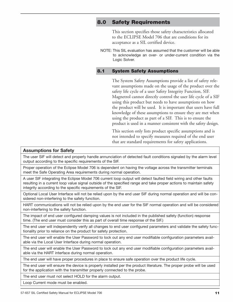
Assumptions for Safety
The user SIF will detect and properly handle annunciation of detected fault conditions signaled by the alarm leveloutput according to the specific requirements of the SIF.
Proper operation of the Eclipse Model 706 is dependent on having the voltage across the transmitter terminalsmeet the Safe Operating Area requirements during normal operation.
A user SIF integrating the Eclipse Model 706 current loop output will detect faulted field wiring and other faultsresulting in a current loop value signal outside of the specified range and take proper actions to maintain safetyintegrity according to the specific requirements of the SIF.
Optional Local User Interface will not be relied upon by the end user SIF during normal operation and will be con-sidered non-interfering to the safety function.
HART communications will not be relied upon by the end user for the SIF normal operation and will be considerednon-interfering to the safety function.
The impact of end user configured damping values is not included in the published safety (function) responsetime. (The end user must consider this as part of overall time response of the SIF.)
The end user will independently verify all changes to end user configured parameters and validate the safety func-tionality prior to reliance on the product for safety protection.
The end user will enable the User Password to lock out any end user modifiable configuration parameters avail-able via the Local User Interface during normal operation.
The end user will enable the User Password to lock out any end user modifiable configuration parameters avail-able via the HART interface during normal operation.
The end user will have proper procedures in place to ensure safe operation over the product life cycle.
The end user will ensure the device is properly installed per the product literature. The proper probe will be usedfor the application with the transmitter properly connected to the probe.
The end user must not select HOLD for the alarm output.
Loop Current mode must be enabled.
8.0 Safety Requirements
This section specifies those safety characteristics allocatedto the ECLIPSE Model 706 that are conditions for itsacceptance as a SIL certified device.
NOTE: This SIL evaluation has assumed that the customer will be ableto acknowledge an over- or under-current condition via theLogic Solver.
8.1 System Safety Assumptions
The System Safety Assumptions provide a list of safety rele-vant assumptions made on the usage of the product over thesafety life cycle of a user Safety Integrity Function, SIF.Magnetrol cannot directly control the user life cycle of a SIFusing this product but needs to have assumptions on howthe product will be used. It is important that users have fullknowledge of these assumptions to ensure they are met whenusing the product as part of a SIF. This is to ensure theproduct is used in a manner consistent with the safety design.
This section only lists product specific assumptions and isnot intended to specify measures required of the end userthat are standard requirements for safety applications.
12 57-657 SIL Certified Safety Manual for ECLIPSE Model 706
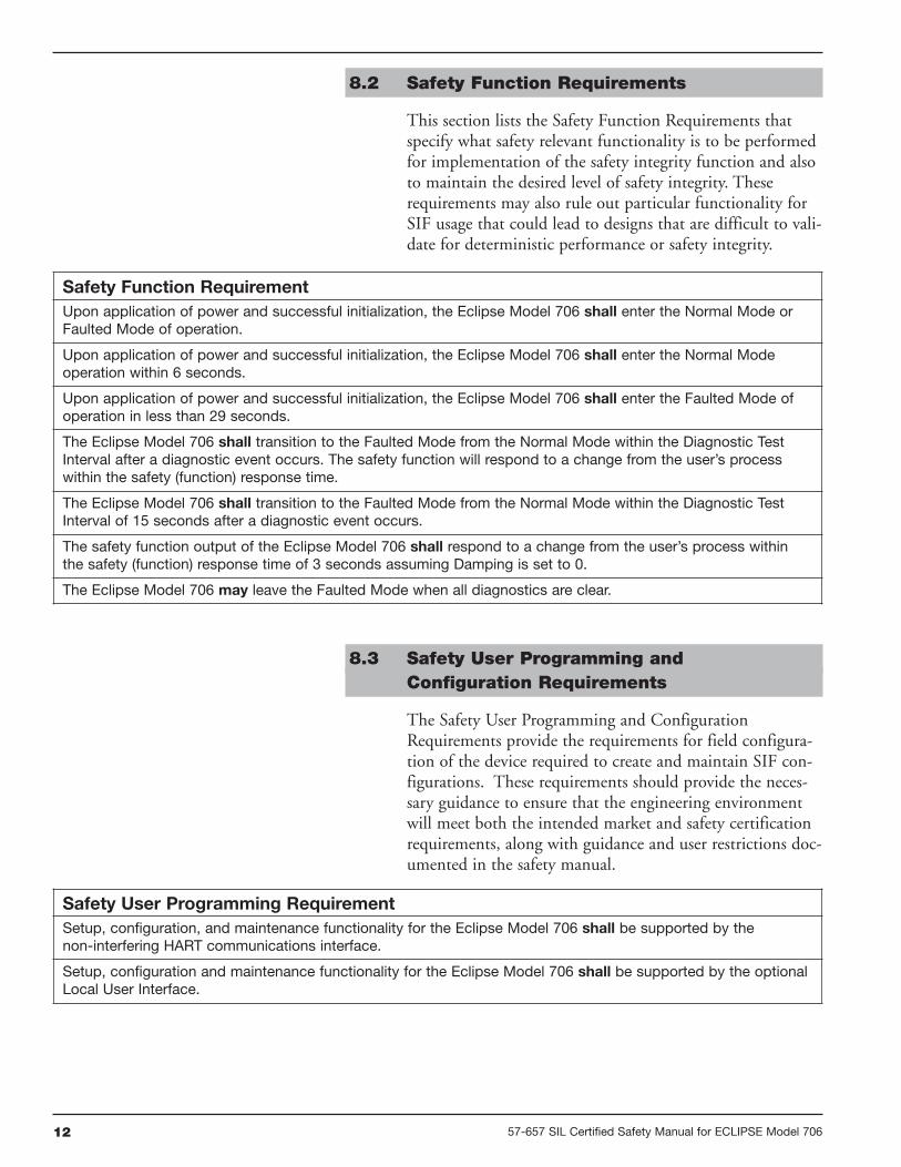
8.2 Safety Function Requirements
This section lists the Safety Function Requirements thatspecify what safety relevant functionality is to be performedfor implementation of the safety integrity function and alsoto maintain the desired level of safety integrity. Theserequirements may also rule out particular functionality forSIF usage that could lead to designs that are difficult to vali-date for deterministic performance or safety integrity.
Safety Function Requirement
Upon application of power and successful initialization, the Eclipse Model 706 shall enter the Normal Mode orFaulted Mode of operation.
Upon application of power and successful initialization, the Eclipse Model 706 shall enter the Normal Modeoperation within 6 seconds.
Upon application of power and successful initialization, the Eclipse Model 706 shall enter the Faulted Mode ofoperation in less than 29 seconds.
The Eclipse Model 706 shall transition to the Faulted Mode from the Normal Mode within the Diagnostic TestInterval after a diagnostic event occurs. The safety function will respond to a change from the user’s processwithin the safety (function) response time.
The Eclipse Model 706 shall transition to the Faulted Mode from the Normal Mode within the Diagnostic TestInterval of 15 seconds after a diagnostic event occurs.
The safety function output of the Eclipse Model 706 shall respond to a change from the user’s process withinthe safety (function) response time of 3 seconds assuming Damping is set to 0.
The Eclipse Model 706 may leave the Faulted Mode when all diagnostics are clear.
8.3 Safety User Programming andConfiguration Requirements
The Safety User Programming and ConfigurationRequirements provide the requirements for field configura-tion of the device required to create and maintain SIF con-figurations. These requirements should provide the neces-sary guidance to ensure that the engineering environmentwill meet both the intended market and safety certificationrequirements, along with guidance and user restrictions doc-umented in the safety manual.
Safety User Programming Requirement
Setup, configuration, and maintenance functionality for the Eclipse Model 706 shall be supported by thenon-interfering HART communications interface.
Setup, configuration and maintenance functionality for the Eclipse Model 706 shall be supported by the optionalLocal User Interface.
1357-657 SIL Certified Safety Manual for ECLIPSE Model 706
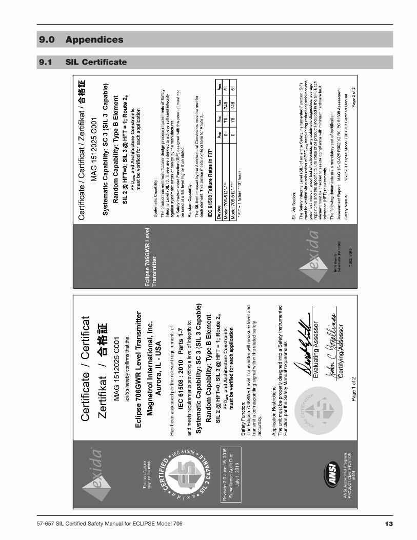
9.0 Appendices
9.1 SIL Certificate
14 57-657 SIL Certified Safety Manual for ECLIPSE Model 706
9.2 FMEDA Report: exida Management Summary

1557-657 SIL Certified Safety Manual for ECLIPSE Model 706
9.3 Specific Model 706 Values
9.4 Report: Lifetime of Critical Components
According to section 7.4.9.5 of IEC 61508-2, a useful life-time, based on experience, should be assumed.
Although a constant failure rate is assumed by probabilisticestimation method, this only applies provided that theuseful lifetime of components is not exceeded. Beyond theiruseful lifetime the result of the probabilistic calculationmethod is therefore meaningless, as the probability of failuresignificantly increases with time. The useful lifetime ishighly dependent on the subsystem itself and its operatingconditions.
The assumption of a constant failure rate is based on thebathtub curve. Therefore it is obvious that the PFDavgcalculation is only valid for components that have thisconstant domain and that the validity of the calculation islimited to the useful lifetime of each component.
The expected useful life of ECLIPSE Model 706-512x-xxxis at least 50 years.
It is the responsibility of the end user to maintain andoperate the Model 706-512x-xxx per manufacturer’s instruc-tions. Furthermore, regular inspection should indicate thatall components are clean and free from damage.
When plant experience indicates a shorter lifetime thanindicated here, the number based on plant experienceshould be used.
ProductECLIPSE
Model 706-512x-xxx
SIL SIL 2
HFT 0
SFF 93.1%
PFDavg Refer to FMEDA report
BULLETIN: 57-657.1
EFFECTIVE: June 2016
SUPERSEDES: June 2016
705 Enterprise Street • Aurora, Illinois 60504-8149 • 630-969-4000 • Fax [email protected] • www.magnetrol.com
Copyright © 2016 Magnetrol International, Incorporated. All rights reserved. Printed in the USA.
ASSURED QUALITY & SERVICE COST LESS
ECLIPSE Guided Wave Radar transmitters may be protected by one or more of the following U.S. Patent Nos.US 6,626,038; US 6,640,629; US 6,642,807; US 6867729; US 6879282; US 6906662. Other patents pending.
DisclaimerThe SIL values in this document are based on an FMEDA analysis using exida’s SILVER Tool. MAGNETROLaccepts no liability whatsoever for the use of these numbers or for the correctness of the standards on which thegeneral calculation methods are based.
Magnetrol, Magnetrol logotype and Eclipse are registered trademarks of Magnetrol International, Incorporated.FOUNDATION fieldbus logo is a registered trademark of the Fieldbus Foundation.HART is a registered trademark of the HART Communication Foundation.PACTware is trademark of PACTware Consortium.
References• IEC 61508 Edition 2.0,2010
“Functional Safety of Electrical/Electronic/Programmable Electronic Safety Related Systems”
• ANSI/ISA-84.00.01-2004 Part 1 (IEC 61511-1Mod)“Functional Safety: Safety Instrumented Systems forthe Process Industry Sector – Part 1 Hardware andSoftware Requirements”
• ANSI/ISA-84.00.01-2004 Part 2 (IEC 61511-2Mod)“Functional Safety: Safety Instrumented Systems forthe Process Industry Sector – Part 2 Guidelines for
the Application of ANSI/ISA84.00.01-2004 Part 1(IEC 61511-1 Mod) – Informative”
• ANSI/ISA-84.00.01-2004 Part 3 (IEC 61511-3Mod)“Functional Safety: Safety Instrumented Systems forthe Process Industry Sector – Part 3 Guidance for theDetermination of the Required Safety Integrity Levels– Informative”
• ANSI/ISA-TR84.00.04 Part 1 (IEC 61511 Mod)“Guideline on the Implementation of ANSI/ISA-84.00.01-2004”
Service PolicyOwners of MAGNETROL controls may request thereturn of a control or any part of a control for completerebuilding or replacement. They will be rebuilt or replacedpromptly. Controls returned under our service policy mustbe returned by prepaid transportation. MAGNETROLwill repair or replace the control at no cost to the pur-chaser (or owner) other than transportation if:
1. Returned within the warranty period; and2. The factory inspection finds the cause of the claim to
be covered under the warranty.
If the trouble is the result of conditions beyond our con-trol; or, is NOT covered by the warranty, there will becharges for labor and the parts required to rebuild orreplace the equipment.
In some cases it may be expedient to ship replacementparts; or, in extreme cases a complete new control, toreplace the original equipment before it is returned. Ifthis is desired, notify the factory of both the model andserial numbers of the control to be replaced. In suchcases, credit for the materials returned will be determinedon the basis of the applicability of our warranty.
No claims for misapplication, labor, direct or consequen-tial damage will be allowed.
Return Material ProcedureSo that we may efficiently process any materials that arereturned, it is essential that a “Return MaterialAuthorization” (RMA) number be obtained from thefactory prior to the material’s return. This is availablethrough a MAGNETROL local representative or by con-tacting the factory. Please supply the following information:
1. Company Name2. Description of Material3. Serial Number4. Reason for Return5. Application
Any unit that was used in a process must be properlycleaned in accordance with OSHA standards, before it isreturned to the factory.
A Material Safety Data Sheet (MSDS) must accompanymaterial that was used in any media.
All shipments returned to the factory must be by prepaidtransportation.
All replacements will be shipped F.O.B. factory.