high iodine adsorption performances under off-gas
TRANSCRIPT

RSC Advances
PAPER
Ope
n A
cces
s A
rtic
le. P
ublis
hed
on 0
7 A
pril
2020
. Dow
nloa
ded
on 2
/9/2
022
5:09
:09
PM.
Thi
s ar
ticle
is li
cens
ed u
nder
a C
reat
ive
Com
mon
s A
ttrib
utio
n-N
onC
omm
erci
al 3
.0 U
npor
ted
Lic
ence
.
View Article OnlineView Journal | View Issue
High iodine adso
aSchool of Chemistry and Chemical Engin
Beijing, 102488, China. E-mail: [email protected] 849, Quality Testing Lab, Center
Technology Tien Nong, Thanh Hoa, 442410cFaculty of Electric-Electronic Engineering
Education, Nam Dinh, 420000, Vietnam
Cite this: RSC Adv., 2020, 10, 14360
Received 17th January 2020Accepted 20th March 2020
DOI: 10.1039/d0ra00501k
rsc.li/rsc-advances
14360 | RSC Adv., 2020, 10, 14360–
rption performances under off-gasconditions by bismuth-modified ZnAl-LDH layereddouble hydroxide
Trinh Dinh Dinh, ab Dongxiang Zhang*a and Vu Ngoc Tuanc
The effective adsorption of radioactive iodine is greatly desirable, but is still a significant challenge. In this
manuscript, we report the synthesis of a bismuth-modified zinc aluminium layered double hydroxide
(BiZnAl-LDH) via a co-precipitation method for the highly efficient absorption of iodine. Based on the
robust chemical attraction between Bi and I2, BiZnAl-LDH exhibited highly effective iodine capture.
Furthermore, to evaluate BiZnAl-LDH as an effective sorbent, it was characterized via X-ray powder
diffraction (XRD), scanning electron microscopy-energy dispersion spectroscopy (SEM-EDS), and
Fourier-transform infrared spectroscopy (FITR). In addition, to determine the morphology and iodine
adsorption properties of BiZnAl-LDH, several studies were conducted. Through experiments, its
elemental composition and vibration before and after iodine adsorption were analyzed via EDS and X-ray
photoelectron spectroscopy (XPS). During the capture process, I2 is reduced to I� by the intercalated
Bi3+ via chemical adsorption, and the maximum adsorption capacity of BiZnAl-LDH for iodine reached
up to 433 mg g�1, which had a surface area, average pore diameter, and pore volume of 36.259 m2 g�1,
2.374 nm, and 0.128 m3 g�1, respectively. Compared with several previous sorbents for iodine
adsorption, BiZnAl-LDH exhibited an iodine adsorption of approximately two times that of the
commercial Ag-exchange zeolite X, and furthermore BiZnAl-LDH is cost-effective. Thus, the substantial
iodine capture by BiZnAl-LDH indicates that it is a capable sorbent for the effective elimination of
radioactive iodine from reprocessing plant emissions.
1. Introduction
With the speedy development of nuclear energy, the saferemoval of radioactive waste generated in the nuclear fuel cyclehas become an issue of great concern to society.1,2 Isotopes ofradioactive iodine are one type of hazardous radionuclideproduced through the nuclear ssion of 235U.3,4
Among the existing isotopes of iodine, 127I is the mostcommon and stable one. Also, 127I can be commonly found infoodstuff, where it is used as an additional nutritional supple-ment (e.g. iodized salt). Furthermore, considering its applica-tion potential as an antimicrobial agent, it is also used forimmediate water sterilization in emergency or critical cases.5 Inaddition, to reduce the chances of the physical uptake of rarerradioactive isotopes from the environment, 127I can be used inlarge doses. Nevertheless, studies reveal6,7 that this approach isdangerous in the long term.
eering, Beijing Institute of Technology,
du.cn; Tel: +86 13366112230
for Research and Development Science
, Vietnam
, Nam Dinh University of Technology
14367
As a result of its application in nuclear industrial energy, the131I isotope has received considerable attention in recent years.131I has found successful applications in the medical industry,where it has become a widely used product for medical imagingin nuclear medicine and radiation therapy. As a byproduct ofthe nuclear energy industry, where it is produced as a result ofthe ssion of uranium, its acquisition, and application incountries that do not use atomic energy is limited. Based on thecomparatively short radioactive half-life of 131I, which is 8 days,it is considered a major health hazard. In some cases, it hasbeen found where a nuclear accident occurred within the rstweek.8 On the other hand, the 129I isotope has a long-termradioactive half-life of over a few million years and is substan-tially less dense than other isotopes. However, 129I is of signif-icant interest in several elds and disciplines such as geologicaland environmental sciences. To quantitatively measure thehuman impact on the atmosphere, 129I can be used as a signif-icant unit measure, in particular the effect of the nuclear blastduring nuclear bomb testing on the new atmosphere.9
There is a vast body of research primarily focused on theradioactive waste products from the exhaust stream. Indeed,there are well-known wet processes designed to trap radioactiveiodine. For example, mercury and alkaline scrubbing haveproven to have highly effective removal capacities, anion
This journal is © The Royal Society of Chemistry 2020

Table 1 The basic reactions for the formation of iodine compounds,and the corresponding changes in the Gibbs free energy (DG) at200 �C calculated using the HSC code.35
Reaction DG (kcal) Spontaneity
Ag + 1/2I2(g) ¼ AgI �16.059 SpontaneousBi + 1/2O2(g) + 1/2I2(g) ¼ BiOI �52.428 SpontaneousBi + 3/2I2(g) ¼ BiI3 �33.376 Spontaneous5Bi + 7/2O2(g) + 1/2I2(g) ¼ Bi5O7I �274.993 Spontaneous5/2Bi2O3 + 1/2I2(g) ¼ Bi5O7I + 1/4O2(g) �5.867 Spontaneous2Bi2O3 + 2I2(g) ¼ 4BiOI + O2(g) 5.588 NonspontaneousBi2O3 + 3I2(g) ¼ 2BiI3 + 3/2O2(g) 40.898 Nonspontaneous
Paper RSC Advances
Ope
n A
cces
s A
rtic
le. P
ublis
hed
on 0
7 A
pril
2020
. Dow
nloa
ded
on 2
/9/2
022
5:09
:09
PM.
Thi
s ar
ticle
is li
cens
ed u
nder
a C
reat
ive
Com
mon
s A
ttrib
utio
n-N
onC
omm
erci
al 3
.0 U
npor
ted
Lic
ence
.View Article Online
exchange resins,10,11 zeolite-based materials,12,13 Ag-basedmaterial,14,15 porous metal–organic frameworks (MOFs),16–19
Cu-based materials,20,21 and in the case of adsorbents for theadsorption of radioactive I�, activated carbon.22 In addition,several research groups have studied the depletion potential ofdifferent iodine species containing I� and IO3
� from aqueoussolutions of layered double hydroxides (LDHs).8,9
LDHs are known as anionic clays materials or hydrotalcite-like compounds, which are coating-stratied clay metalsbased on a similar structure to the brucite Mg(OH)2. LDHs alsopresent a layered structure that carries a net positive charge.Their exchangeable anions are balanced by the positive chargeconstituents of the alternating cation layers in the alternatingregions of LDHs. The common formula of LDHs is character-ized by M2+
1�yM3+y (OH)y+2 (An�)y/n$mH2O where the divalent metal
M2+ is Ni2+, Cu2+, Mg2+ and Zn2+ cation, the trivalent metal M3+
is Ti3+, Al3+, Bi3+ and Fe3+ cation, usually chloride, nitrate orcarbonate is the exchangeable anion and y is usually 0.2 < y <0.33.23,24 The structure and composition of LDH compoundshave been the focus of considerable research. In addition, therecent work by Mills et al. based on hydrotalcite LDHs exhibitedan interesting property in terms of composition and nomen-clature called the reform effect (or remembrance).25 Basic metaladsorbents have been effectively applied in iodine adsorption.Moreover, Nenoff and colleagues conducted substantial workaimed at advancing layered hydrotalcite-like oxides-I-Bi as wasteforms for iodine precipitation. As a result, it was found that theiodine phase composition in oxides-I-Bi was determinedaccording to the Bi : I ratio,26,27 and the compounds containingbismuth showed several important advantages such as theability to react with iodine and iodide capture capacity, andBi2O3 was also comprehensively investigated for iodine immo-bilization adsorption.28–30
It was reported that the surface modication of layereddouble hydroxide electrodes with an additive, such as Bi, canenhance the chemical properties of the active materials.31–33
Also, layered double hydroxide materials have been investigatedas additives due their effect on the environment. The mainadditives to Al include bismuth and other non-metallicelements, including other bismuth compounds and Bi2O3.These bismuth compounds can prove the linkage efficiencybetween Bi and the zinc metal matrix.34 Moreover, an Al–Bimixed system can allow Bi-phase stabilization and overcomesome of the limitations of Al.
We investigated bismuth for the capture of iodine gas. Thereactions between iodine and bismuth demonstrate the char-acteristic properties of the gas–solid reaction in the iodineadsorption process. Table 1 clearly shows the highly exothermicnature of this reaction and that the iodine adsorption capacityof Bi is better than that of silver and Bi2O3.
High iodine adsorption efficiency is highly desirable, butthere are still major challenges in long-term iodine storagerequirements for adsorbent materials. Recently, many LDH-type materials (such as NiTi-LDH and MgAl-LDH) have shownhigh iodine adsorption efficiency based on chemical adsorp-tion. However, the chemical adsorption of iodine is still limitedin an aqueous environment.4,9 Chemical adsorption combined
This journal is © The Royal Society of Chemistry 2020
with physical adsorption on NiTi-Sx-LDH in a humid air envi-ronment was considered to be an effective method for iodineadsorption for short-term storage.36
Herein, various LDHs compounds were synthesized andcharacterized, where different amounts of Bi were used tomodify the chemical activate characteristics of the LDHs. Theexperiments used the strong chemical attractions betweeniodine and bismuth in ZnAl LDH modied by Bi absorbents.Accordingly, BiZnAl-LDH was applied for iodine adsorption andstorage over long periods.
2. Materials and methods2.1. Materials
Zinc nitrate (Zn(NO3)2$6H2O), sodium hydroxide (NaOH),aluminum nitrate (Al(NO3)3$9H2O), bismuth nitrate (Bi(NO3)3-$5H2O), sodium carbonate (Na2CO3), and nitric acid (HNO3)were purchased from Aladdin (China). All chemicals were usedas received no additional pretreatment or purication.
2.2. Preparation of ZnAl-LDH modied by Bi
The BiZnAl-LDH adsorbent used herein was prepared viaa coprecipitation method, which was previously reported.4 Zincnitrate (Zn(NO3)2$6H2O) and aluminum nitrate (Al(NO3)3-$9H2O) were each dissolved in 200mL deionized water, bismuthnitrate (Bi(NO3)3$5H2O) was dissolved in concentrated nitricacid solution before adding water, and mixtures with theBi : Zn : Al molar ratios of 0.1 : 3 : 0.9 (B1), 0.2 : 3 : 0.8 (B2),0.3 : 3 : 0.7 (B3) and 0.4 : 3 : 0.6 (B4) were prepared. Next,200 mL of mixed solution containing NaOH (0.08 mol) andNa2CO3 (0.03 mol) were added to the above solution andvigorously stirred with a pH value of 9.5 at room temperature.Then, the obtained solution was transferred to a 500 mL two-necked ask and le to react for 24 h at 90 �C. The mixturewas carefully ltered and washed with ultra-pure water severaltimes and dried overnight at 60 �C to obtain a white coloredpowder. The product BiZnAl-LDH was then collected in a smallglass bottle for further examination and iodine adsorptionexperiments.
2.3. Characterization techniques
In this experiment, pH was monitored an IS128 pH-meter. ANICOLET-IS5 FT-IR spectrometer was used to record Fourier-
RSC Adv., 2020, 10, 14360–14367 | 14361
RSC Advances Paper
Ope
n A
cces
s A
rtic
le. P
ublis
hed
on 0
7 A
pril
2020
. Dow
nloa
ded
on 2
/9/2
022
5:09
:09
PM.
Thi
s ar
ticle
is li
cens
ed u
nder
a C
reat
ive
Com
mon
s A
ttrib
utio
n-N
onC
omm
erci
al 3
.0 U
npor
ted
Lic
ence
.View Article Online
transformed infrared spectra (FT-IR) in the wavenumber rangeof 400–4000 cm�1. The morphology and energy dispersive X-rayspectroscopy (EDX) element mapping analysis of the sampleswere performed on a scanning electron microscope (SEM, JSM-7800F) and transmission electron microscope (HRTEM, TEM,JEOL-LEM-2100F). Powder X-ray diffraction (XRD, RigakuUltima IV) patterns were measured on a DMAX2500 in the 2qrange of 5–80� at a scanning rate of 8� per minute. X-rayphotoelectron spectroscopy (XPS) was performed on a ThermoESCALab 250XI. Thermogravimetric analysis (TGA) was per-formed using an STA 449 F3 thermogravimetry analyzer ata heating rate of 10 �C min�1 in the temperature range of 25 �Cto 800 �C under an N2 atmosphere.
2.4. Iodine adsorption experiments
To address the feasibility of different adsorbents, one of the keyparameters is their iodine adsorption capacity. Accordingly,during the adsorption test, the adsorbed mass was measured todetermine the above-mentioned iodine adsorption capacity.The iodine adsorption experiment was conducted according tothe following procedure.30 Firstly, an excess of 0.2 g I2 was addedthe bottom of a serum bottle, and then, a small amount ofaround 100 mg of the adsorbent was placed in a conical discplate on top of the bottle. The vial was closed and sealed, andthe glass bottle was heated at 75 �C and ambient pressure.Thereaer (1–2 days), the bottle was cooled to room tempera-ture, and the iodine capture was estimated by weighing. Aer-wards, by considering the ratio between the reaction products,the mass of iodine existing in the adsorbed mass was calcu-lated. It is worth mentioning that the adsorbed mass was ob-tained by taking the difference between the sample mass beforethe experiment was conducted and that obtained aer. A digitalbalance with a specicity of 104 was employed. In addition, tocalculate the adsorbed mass, the nal mass was measuredtwice. The amount of iodine existing in the above-mentionedadsorbed mass was determined by means of analyzing thereaction products. Additionally, ZnAl-LDH and the commercialAgX reported by Mnasri et al. were used for comparison. Theiodine adsorption experiments were repeated three times andthe results of the average value (relative standard error less than5%) were utilized for the data analysis. The iodine adsorption ofBiZnAl-LDH was calculated using formulas (1), and a schematicof the experimental setup is shown in Fig. 1.
Fig. 1 Schematic of the device for the iodine adsorption experimentsin static air.
14362 | RSC Adv., 2020, 10, 14360–14367
Q
�mg
g
�¼ Dm
ms
� 1000 (1)
where Q (mg g�1) is the iodine adsorption,ms is the initial mass,and Dm is the mass gain of the sorbent.
3. Results and discussion3.1. Characterization of BiZnAl-LDH
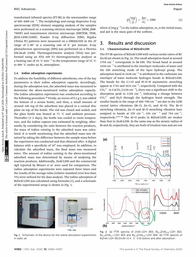
The FT-IR spectra of BiZnAl-LDHwith various molar ratios of Bi/Zn/Al are shown in Fig. 2a. The small adsorption band at around3769 cm�1 corresponds to M–OH. The broad band at around3450 cm�1 is attributed to the interlayer molecules of water andthe OH stretching mode of the layer hydroxyl group. Theadsorption band at 2438 cm�1 is attributed to the carbonate ioninterlayer of water molecule hydrogen bonds in BiZnAl-LDH.The bands for the C]O and H–O–H asymmetric stretchingappear at 1745 and 1631 cm�1, respectively. Compared with theCO3
2� in CaCO3 (1430 cm�1), there was a signicant shi in theabsorption peak to 1349 cm�1, indicating a change betweenCO3
2� and H2O through the hydrogen bond strength. Thesmaller bands in the range of 400–700 cm�1 are due to the LDHcrystal lattice vibrations (Bi–O, Zn–O, and Al–O). The Bi–Ostretching vibration, Zn–O and Al–O stretching vibration hareassigned to bands at 550 cm�1, 436 cm� 1 and 764 cm�1,respectively.31,37–39 The Al–O peaks in BiZnAl-LDH are weakerthan that in ZnAl-LDH. In the same way as the atomic radius ofBi and Al, respectively, they are both of trivalent ions and are not
Fig. 2 (a) FTIR spectra of ZnAl-LDH (B0), Bi0.2ZnAl0.8-LDH (B2),Bi0.3ZnAl0.7-LDH (B3) and Bi0.4ZnAl0.6-LDH (B4). (b) FTIR spectra ofBiZnAl-LDH (Bi/Zn/Al¼0.4 : 3 : 0.6) before and after adsorption.
This journal is © The Royal Society of Chemistry 2020

Fig. 3 SEM images of ZnAl-LDH (a), B2 (b), B3 (c) and B4 (d).
Fig. 5 XRD patterns of ZnAl-LDH, Bi0.2ZnAl0.8-LDH (B2), Bi0.3ZnAl0.7-LDH (B3) and Bi0.4ZnAl0.6-LDH (B4).
Paper RSC Advances
Ope
n A
cces
s A
rtic
le. P
ublis
hed
on 0
7 A
pril
2020
. Dow
nloa
ded
on 2
/9/2
022
5:09
:09
PM.
Thi
s ar
ticle
is li
cens
ed u
nder
a C
reat
ive
Com
mon
s A
ttrib
utio
n-N
onC
omm
erci
al 3
.0 U
npor
ted
Lic
ence
.View Article Online
signicant. The bismuth atoms can exchange with some of thealuminum atoms in the framework. However, the addition of Bidid not affect the crystal structure of the substrate, and the FT-IR spectrum of BiZnAl-LDH shows that Bi was effectivelyinserted into the ZnAl-LDH framework.
The FTIR spectrum in Fig. 2b aer the sorption experimentshows that the I� ion was present in BiZnAl-LDH-I. The strongbands in the range of 400–700 cm�1 are due to the LDH-iodinecrystal lattice vibrations (BiI3 and I2–ZnAl2O4).
The characteristic SEM images of BiZnAl-LDH with differentBi/Zn/Al mole ratios and ZnAl-LDH are depicted in Fig. 3. It isobvious that all three BiZnAl-LDH samples exhibit a layeredhexagonal structure similar to the typical structure of ZnAl-LDHwith the layered hexagonal structure of ZnAl2O4.39 The particlesize and thickness of BiZnAl-LDH is about 200–300 nm and40 nm, respectively. These results show that the lattice structure
Fig. 4 (a) TEM image, (b) HRTEM image, (c) EDS results and (d) element
This journal is © The Royal Society of Chemistry 2020
of the material was not destroyed aer the addition of theappropriate amount of Bi.40 Thus, based on the analysis above,BiZnAl-LDH was successfully synthesized through the co-precipitation method.39
Furthermore, the layered hexagonal structure of BiZnAl-LDHwas studied via EDS, HRTEM, and TEM, as showed in Fig. 4. TheTEM image in Fig. 4a and HRTEM image in Fig. 4b demonstratethat BiZnAl-LDH is mostly composed of different diameters ofthe hexagonal spherical particles. The typical HRTEM image, aspresented in Fig. 4b, shows the layer structure of BiZnAl-LDHwith d-spacings of 0.23 and 0.24 nm, corresponding to thedifferent lattice planes of Bi and ZnAl2O4, respectively.41–43
Fig. 4d shows the EDS mapping of a spherical particle, whichwas used to determine the composition of the hexagonalspherical particles of BiZnAl-LDH, conrming the results fromthe XPS analysis.
The XRD patterns of the samples are compared in Fig. 5.According to JCPDS: 48–1023, ZnAl-LDH shows extremediffraction peaks located at 2q ¼ 11.98�, 23.84�, 35.06� and
mapping image of BiZnAl-LDH (Bi/Zn/Al¼0.4 : 3 : 0.6).
RSC Adv., 2020, 10, 14360–14367 | 14363
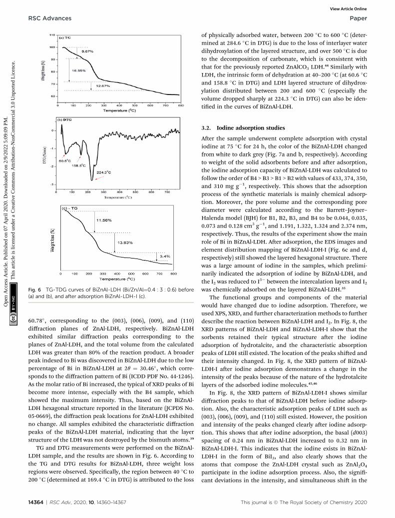
Fig. 6 TG-TDG curves of BiZnAl-LDH (Bi/Zn/Al¼0.4 : 3 : 0.6) before(a) and (b), and after adsorption BiZnAl-LDH-I (c).
RSC Advances Paper
Ope
n A
cces
s A
rtic
le. P
ublis
hed
on 0
7 A
pril
2020
. Dow
nloa
ded
on 2
/9/2
022
5:09
:09
PM.
Thi
s ar
ticle
is li
cens
ed u
nder
a C
reat
ive
Com
mon
s A
ttrib
utio
n-N
onC
omm
erci
al 3
.0 U
npor
ted
Lic
ence
.View Article Online
60.78�, corresponding to the (003), (006), (009), and (110)diffraction planes of ZnAl-LDH, respectively. BiZnAl-LDHexhibited similar diffraction peaks corresponding to theplanes of ZnAl-LDH, and the total volume from the calculatedLDH was greater than 80% of the reaction product. A broaderpeak indexed to Bi was discovered in BiZnAl-LDH due to the lowpercentage of Bi in BiZnAl-LDH at 2q ¼ 30.46�, which corre-sponds to the diffraction pattern of Bi (ICDD PDF No. 44-1246).As the molar ratio of Bi increased, the typical of XRD peaks of Bibecome more intense, especially with the B4 sample, whichshowed the maximum intensity. Thus, based on the BiZnAl-LDH hexagonal structure reported in the literature (JCPDS No.05-0669), the diffraction peak locations for ZnAl-LDH exhibitedno change. All samples exhibited the characteristic diffractionpeaks of the BiZnAl-LDH material, indicating that the layerstructure of the LDH was not destroyed by the bismuth atoms.39
TG and DTG measurements were performed on the BiZnAl-LDH sample, and the results are shown in Fig. 6. According tothe TG and DTG results for BiZnAl-LDH, three weight lossregions were observed. Specically, the region between 40 �C to200 �C (determined at 169.4 �C in DTG) is attributed to the loss
14364 | RSC Adv., 2020, 10, 14360–14367
of physically adsorbed water, between 200 �C to 600 �C (deter-mined at 284.6 �C in DTG) is due to the loss of interlayer waterdihydroxylation of the layered structure, and over 500 �C is dueto the decomposition of carbonate, which is consistent withthat for the previously reported ZnAlCO3 LDH.44 Similarly withLDH, the intrinsic form of dehydration at 40–200 �C (at 60.6 �Cand 158.8 �C in DTG) and LDH layered structure of dihydrox-ylation distributed between 200 and 600 �C (especially thevolume dropped sharply at 224.3 �C in DTG) can also be iden-tied in the curves of BiZnAl-LDH.
3.2. Iodine adsorption studies
Aer the sample underwent complete adsorption with crystaliodine at 75 �C for 24 h, the color of the BiZnAl-LDH changedfrom white to dark grey (Fig. 7a and b, respectively). Accordingto weight of the solid adsorbents before and aer adsorption,the iodine adsorption capacity of BiZnAl-LDH was calculated tofollow the order of B4 > B3 > B1 > B2 with values of 433, 374, 350,and 310 mg g�1, respectively. This shows that the adsorptionprocess of the synthetic materials is mainly chemical adsorp-tion. Moreover, the pore volume and the corresponding porediameter were calculated according to the Barrett–Joyner–Halenda model (BJH) for B1, B2, B3, and B4 to be 0.044, 0.035,0.073 and 0.128 cm3 g�1, and 1.191, 1.322, 1.324 and 2.374 nm,respectively. Thus, the results of the experiment show the mainrole of Bi in BiZnAl-LDH. Aer adsorption, the EDS images andelement distribution mapping of BiZnAl-LDH-I (Fig. 6c and d,respectively) still showed the layered hexagonal structure. Therewas a large amount of iodine in the samples, which prelimi-narily indicated the adsorption of iodine by BiZnAl-LDH, andthe I2 was reduced to I3� between the intercalation layers and I2was chemically adsorbed on the layered BiZnAl-LDH.35
The functional groups and components of the materialwould have changed due to iodine adsorption. Therefore, weused XPS, XRD, and further characterization methods to furtherdescribe the reaction between BiZnAl-LDH and I2. In Fig. 8, theXRD patterns of BiZnAl-LDH and BiZnAl-LDH-I show that thesorbents retained their typical structure aer the iodineadsorption of hydrotalcite, and the characteristic absorptionpeaks of LDH still existed. The location of the peaks shied andtheir intensity changed. In Fig. 8, the XRD pattern of BiZnAl-LDH-I aer iodine adsorption demonstrates a change in theintensity of the peaks because of the nature of the hydrotalcitelayers of the adsorbed iodine molecules.45,46
In Fig. 8, the XRD pattern of BiZnAl-LDH-I shows similardiffraction peaks to that of BiZnAl-LDH before iodine adsorp-tion. Also, the characteristic adsorption peaks of LDH such as(003), (006), (009), and (110) still existed. However, the positionand intensity of the peaks changed clearly aer iodine adsorp-tion. This shows that aer iodine adsorption, the basal (d003)spacing of 0.24 nm in BiZnAl-LDH increased to 0.32 nm inBiZnAl-LDH-I. This indicates that the iodine exists in BiZnAl-LDH-I in the form of BiI3, and also clearly shows that theatoms that compose the ZnAl-LDH crystal such as ZnAl2O4
participate in the iodine adsorption process. Also, the signi-cant deviations in the intensity, and simultaneous shi in the
This journal is © The Royal Society of Chemistry 2020
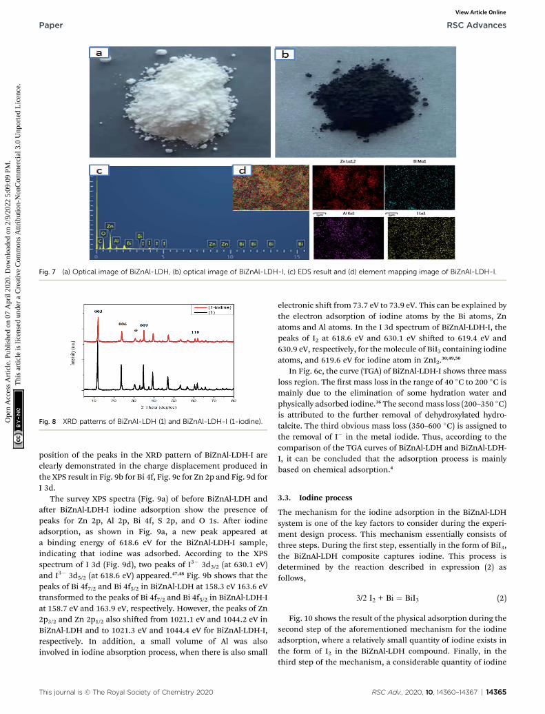
Fig. 7 (a) Optical image of BiZnAl-LDH, (b) optical image of BiZnAl-LDH-I, (c) EDS result and (d) element mapping image of BiZnAl-LDH-I.
Fig. 8 XRD patterns of BiZnAl-LDH (1) and BiZnAl-LDH-I (1-iodine).
Paper RSC Advances
Ope
n A
cces
s A
rtic
le. P
ublis
hed
on 0
7 A
pril
2020
. Dow
nloa
ded
on 2
/9/2
022
5:09
:09
PM.
Thi
s ar
ticle
is li
cens
ed u
nder
a C
reat
ive
Com
mon
s A
ttrib
utio
n-N
onC
omm
erci
al 3
.0 U
npor
ted
Lic
ence
.View Article Online
position of the peaks in the XRD pattern of BiZnAl-LDH-I areclearly demonstrated in the charge displacement produced inthe XPS result in Fig. 9b for Bi 4f, Fig. 9c for Zn 2p and Fig. 9d forI 3d.
The survey XPS spectra (Fig. 9a) of before BiZnAl-LDH andaer BiZnAl-LDH-I iodine adsorption show the presence ofpeaks for Zn 2p, Al 2p, Bi 4f, S 2p, and O 1s. Aer iodineadsorption, as shown in Fig. 9a, a new peak appeared ata binding energy of 618.6 eV for the BiZnAl-LDH-I sample,indicating that iodine was adsorbed. According to the XPSspectrum of I 3d (Fig. 9d), two peaks of I3� 3d3/2 (at 630.1 eV)and I3� 3d5/2 (at 618.6 eV) appeared.47,48 Fig. 9b shows that thepeaks of Bi 4f7/2 and Bi 4f5/2 in BiZnAl-LDH at 158.3 eV 163.6 eVtransformed to the peaks of Bi 4f7/2 and Bi 4f5/2 in BiZnAl-LDH-Iat 158.7 eV and 163.9 eV, respectively. However, the peaks of Zn2p3/2 and Zn 2p1/2 also shied from 1021.1 eV and 1044.2 eV inBiZnAl-LDH and to 1021.3 eV and 1044.4 eV for BiZnAl-LDH-I,respectively. In addition, a small volume of Al was alsoinvolved in iodine absorption process, when there is also small
This journal is © The Royal Society of Chemistry 2020
electronic shi from 73.7 eV to 73.9 eV. This can be explained bythe electron adsorption of iodine atoms by the Bi atoms, Znatoms and Al atoms. In the I 3d spectrum of BiZnAl-LDH-I, thepeaks of I2 at 618.6 eV and 630.1 eV shied to 619.4 eV and630.9 eV, respectively, for the molecule of BiI3 containing iodineatoms, and 619.6 eV for iodine atom in ZnI2.30,49,50
In Fig. 6c, the curve (TGA) of BiZnAl-LDH-I shows three massloss region. The rst mass loss in the range of 40 �C to 200 �C ismainly due to the elimination of some hydration water andphysically adsorbed iodine.36 The secondmass loss (200–350 �C)is attributed to the further removal of dehydroxylated hydro-talcite. The third obvious mass loss (350–600 �C) is assigned tothe removal of I� in the metal iodide. Thus, according to thecomparison of the TGA curves of BiZnAl-LDH and BiZnAl-LDH-I, it can be concluded that the adsorption process is mainlybased on chemical adsorption.4
3.3. Iodine process
The mechanism for the iodine adsorption in the BiZnAl-LDHsystem is one of the key factors to consider during the experi-ment design process. This mechanism essentially consists ofthree steps. During the rst step, essentially in the form of BiI3,the BiZnAl-LDH composite captures iodine. This process isdetermined by the reaction described in expression (2) asfollows,
3/2 I2 + Bi ¼ BiI3 (2)
Fig. 10 shows the result of the physical adsorption during thesecond step of the aforementioned mechanism for the iodineadsorption, where a relatively small quantity of iodine exists inthe form of I2 in the BiZnAl-LDH compound. Finally, in thethird step of the mechanism, a considerable quantity of iodine
RSC Adv., 2020, 10, 14360–14367 | 14365

Fig. 9 (a) XPS survey spectra, (b) Bi 4f, (c) Zn 2p and (d) I 3d of BiZnAl-LDH (1) and BiZnAl-LDH-I (1-iodine).
Fig. 10 Proposed mechanism of the iodine adsorption reaction onBiZnAl-LDH.
14366 | RSC Adv., 2020, 10, 14360–14367
RSC Advances Paper
Ope
n A
cces
s A
rtic
le. P
ublis
hed
on 0
7 A
pril
2020
. Dow
nloa
ded
on 2
/9/2
022
5:09
:09
PM.
Thi
s ar
ticle
is li
cens
ed u
nder
a C
reat
ive
Com
mon
s A
ttrib
utio
n-N
onC
omm
erci
al 3
.0 U
npor
ted
Lic
ence
.View Article Online
is captured due to ZnAl2O4, which is an expected resultconsidering the chemical doping nature of the reaction involvedin this third and nal of the adsorption mechanism.
4. Conclusion
Herein, we reported the successful synthesis of BiZnAl-LDHthrough a co-precipitation method. The phase identity, opticalresponse, and morphological structure of the hexagonal mate-rial were systematically characterized by FTIR, BET, SEM-EDS,XRD, XPS, TEM, HRTEM, and TG-DSC. In addition, the experi-mental procedures were carried out under the conditions of Bi/Al ratio of 0.4 : 0.6, for 24 h at 90 �C, and the highest adsorptioncapacity of the material was calculated to be about 433 (mg g�1),which is approximately two times that of the commercial Ag-exchange zeolite X. Moreover, the surface area, pore volume,and average pore diameter of the as-synthesized material were36.259 (m2 g�1), 0.128 (cm3 g�1), and 2.374 (nm), respectively.Furthermore, the BiZnAl-LDH material presented a hexagonalshape formed by ZnAl-LDH modied by Bi. Our results showedthat iodine can be captured by mixing with BiZnAl-LDH throughthe reaction of bismuth, zinc, and doped ZnAl2O4. Moreover,our results showed that LDH-modied products of Bi can beused to adsorb iodine from fuel gas to replace the Ag-exchangezeolite X.
Author contributions
The manuscript was written through contributions of allauthors. All authors have given approval to the nal version ofthe manuscript.
Funding sources
This work was supported by the China Scholarship Council(2017GXZ019688).
Conflicts of interest
There are no conicts to declare.
Acknowledgements
The authors acknowledge the valuable contributions of theBeijing Institute of Technology Analysis & Testing Center.
This journal is © The Royal Society of Chemistry 2020

Paper RSC Advances
Ope
n A
cces
s A
rtic
le. P
ublis
hed
on 0
7 A
pril
2020
. Dow
nloa
ded
on 2
/9/2
022
5:09
:09
PM.
Thi
s ar
ticle
is li
cens
ed u
nder
a C
reat
ive
Com
mon
s A
ttrib
utio
n-N
onC
omm
erci
al 3
.0 U
npor
ted
Lic
ence
.View Article Online
References
1 L. He, S. Liu, L. Chen, X. Dai, J. Li, M. Zhang, F. Ma, C. Zhang,Z. Yang, R. Zhou, Z. Chai and S. Wang, Chem. Sci., 2019, 10,4293–4305.
2 J. Yu, X. Luo, B. Liu, J. Zhou, J. Feng, W. Zhu, S. Wang,Y. Zhang, X. Lin and P. Chen, J. Mater. Chem. A, 2018, 6,15359–15370.
3 J. Li, X. Dai, L. Zhu, C. Xu, D. Zhang, M. A. Silver, P. Li,L. Chen, Y. Li, D. Zuo, H. Zhang, C. Xiao, J. Chen, J. Diwu,O. K. Farha, T. E. Albrecht-Schmitt, Z. Chai and S. Wang,Nat. Commun., 2018, 9, 1–11.
4 G. Lin, L. Zhu, T. Duan, L. Zhang, B. Liu and J. Lei, Chem.Eng. J., 2019, 378, 122181.
5 Z. Ding, J. T. Kloprogge, R. L. Frost, G. Q. Lu and H. Y. Zhu, J.Porous Mater., 2001, 8, 273–293.
6 M. Takahashi, M. Takeda and Y. Ito,Hyperne Interact., 1994,84, 575–581.
7 P. Yi, A. Aldahan, V. Hansen, G. Possnert and X. L. Hou,Environ. Sci. Technol., 2011, 45, 903–909.
8 G. Fetter, E. Ramos, M. T. Olguin, P. Bosch, T. Lopez andS. Bulbulian, J. Radioanal. Nucl. Chem., 1997, 221, 63–66.
9 F. L. Theiss, G. A. Ayoko and R. L. Frost, Chem. Eng. J., 2016,296, 300–309.
10 J. Warchoł, P. Misaelides, R. Petrus and D. Zamboulis, J.Hazard. Mater., 2006, 137, 1410–1416.
11 A. E. Osmanlioglu, J. Hazard. Mater., 2006, 137, 332–335.12 J. Zhou, S. Hao, L. Gao and Y. Zhang, Ann. Nucl. Energy, 2014,
72, 237–241.13 F. Yu, Y. Chen, Y. Wang, C. Liu and W. Ma, Appl. Surf. Sci.,
2018, 427, 753–762.14 I. Framework, D. F. Sava, M. A. Rodriguez, K. W. Chapman,
P. J. Chupas, J. A. Greathouse, P. S. Crozier and T. M. Nenoff,J. Am. Chem. Soc., 2011, 12398–12401.
15 D. Yang, S. Sarina, H. Zhu, H. Liu, Z. Zheng, M. Xie, S. VSmith and S. Komarneni, Angew. Chem., Int. Ed., 2011, 50,10594–10598.
16 J. Liu, L. Chen, H. Cui, J. Zhang, L. Zhang and C. Y. Su, Chem.Soc. Rev., 2014, 43, 6011–6061.
17 T. D. Bennett, P. J. Saines, D. A. Keen, J. C. Tan andA. K. Cheetham, Chem.–Eur. J., 2013, 19, 7049–7055.
18 J. T. Hughes, D. F. Sava, T. M. Nenoff and A. Navrotsky, J. Am.Chem. Soc., 2013, 135, 16256–16259.
19 M. Sanchez-Polo, J. Rivera-Utrilla, E. Salhi and U. vonGunten, Water Res., 2007, 41, 1031–1037.
20 X. Zhang, P. Gu, X. Li and G. Zhang, Chem. Eng. J., 2017, 322,129–139.
21 P. Mao, J. Jiang, Y. Pan, C. Duanmu, S. Chen, Y. Yang,S. Zhang and Y. Chen, Materials, 2018, 11, 1–11.
22 C. M. Yang and K. Kaneko, J. Colloid Interface Sci., 2002, 246,34–39.
23 V. Rives, Mater. Chem. Phys., 2002, 75, 19–25.24 Y. Zhao, R. L. Frost and W. N. Martens, J. Phys. Chem. C,
2007, 111, 16290–16299.
This journal is © The Royal Society of Chemistry 2020
25 G. Mascolo and M. C. Mascolo, Microporous MesoporousMater., 2015, 214, 246–248.
26 J. L. Krumhansl and T. M. Nenoff, Appl. Geochem., 2011, 26,57–64.
27 T. Nenoff, J. L. Krumhansl and A. Rajan, Mater. Res. Soc.Symp. Proc., 2008, 1043, 329–334.
28 L. Zhang, A. A. S. Gonçalves, B. Jiang and M. Jaroniec,ChemSusChem, 2018, 11, 1486–1493.
29 J. H. Yang, Y. J. Cho, J. M. Shin and M. S. Yim, J. Nucl. Mater.,2015, 465, 556–564.
30 H. Zou, F. Yi, M. Song, X. Wang, L. Bian, W. Li, N. Pan andX. Jiang, J. Hazard. Mater., 2019, 365, 81–87.
31 H. Li, Q. Deng, J. Liu, W. Hou, N. Du, R. Zhang and X. Tao,Catal. Sci. Technol., 2014, 4, 1028–1037.
32 D. Sokol, M. Ivanov, A. N. Salak, R. Grigalaitis, J. Banys andA. Kareiva, Mater. Sci.-Pol., 2019, 37, 190–195.
33 A. Jaiswal and M. C. Chattopadhyaya, Arabian J. Chem., 2017,10, S2457–S2463.
34 J. Long, Z. Yang, X. Zeng and J. Huang, RSC Adv., 2016, 6,92896–92904.
35 J. Hwan, J. Myeong, J. Jin, G. Il and M. Sung, J. Nucl. Mater.,2015, 457, 1–8.
36 S. Ma, S. M. Islam, Y. Shim, Q. Gu, P. Wang, H. Li, G. Sun,X. Yang and M. G. Kanatzidis, Chem. Mater., 2014, 26,7114–7123.
37 R. C. Zeng, X. T. Li, Z. G. Liu, F. Zhang, S. Q. Li and H. Z. Cui,Front. Mater. Sci., 2015, 9, 355–365.
38 C. Bi, J. Li, L. Peng and J. Zhang, Biomed. Res., 2017, 28,2065–2069.
39 Z. Zhang, Z. Yang, J. Huang, Z. Feng and X. Xie, Electrochim.Acta, 2015, 155, 61–68.
40 R. Wang, Z. Yang, B. Yang, T. Wang and Z. Chu, J. PowerSources, 2014, 251, 344–350.
41 S. Sepulveda-Guzman, N. Elizondo-Villarreal, D. Ferrer,A. Torres-Castro, X. Gao, J. P. Zhou and M. Jose-Yacaman,Nanotechnology, 2007, 18, 33.
42 L. Zou, F. Li, X. Xiang, D. G. Evans and X. Duan, Chem.Mater., 2006, 18, 5852–5859.
43 Y. Zhao, M. Wei, J. Lu, Z. L. Wang and X. Duan, ACS Nano,2009, 3, 4009–4016.
44 Z. Li, M. Chen, Q. Zhang, J. Qu, Z. Ai and Y. Li, Appl. Clay Sci.,2017, 144, 115–120.
45 N. Iyi, T. Matsumoto, Y. Kaneko and K. Kitamura, 2004,2926–2932.
46 M. Bastianini, D. Costenaro, C. Bisio, L. Marchese,U. Costantino, R. Vivani and M. Nocchetti, Inorg. Chem.,2012, 51, 2560–2568.
47 K. Li, Y. Zhao, P. Zhang, C. He, J. Deng, S. Ding and W. Shi,Appl. Surf. Sci., 2016, 390, 412–421.
48 D. K. L. Harijan, V. Chandra, T. Yoon and K. S. Kim, J.Hazard. Mater., 2018, 344, 576–584.
49 D. Xu, D. Fan and W. Shen, Nanoscale Res. Lett., 2013, 8, 1–9.50 F. Barka-Bouaifel, B. Sieber, N. Bezzi, J. Benner, P. Roussel,
L. Boussekey, S. Szunerits and R. Boukherroub, J. Mater.Chem., 2011, 21, 10982–10989.
RSC Adv., 2020, 10, 14360–14367 | 14367