high induction long throw diffusers for deep jet …
TRANSCRIPT
N°hole
s33336666
*KV 230S: without internal cone
HIGH INDUCTION LONG THROWDIFFUSERS FOR DEEP JET KV
SERIESTECHNICAL CHARACTERISTICS
STANDARD WITH CONNECTION
FOR FLEXIBLE DUCT
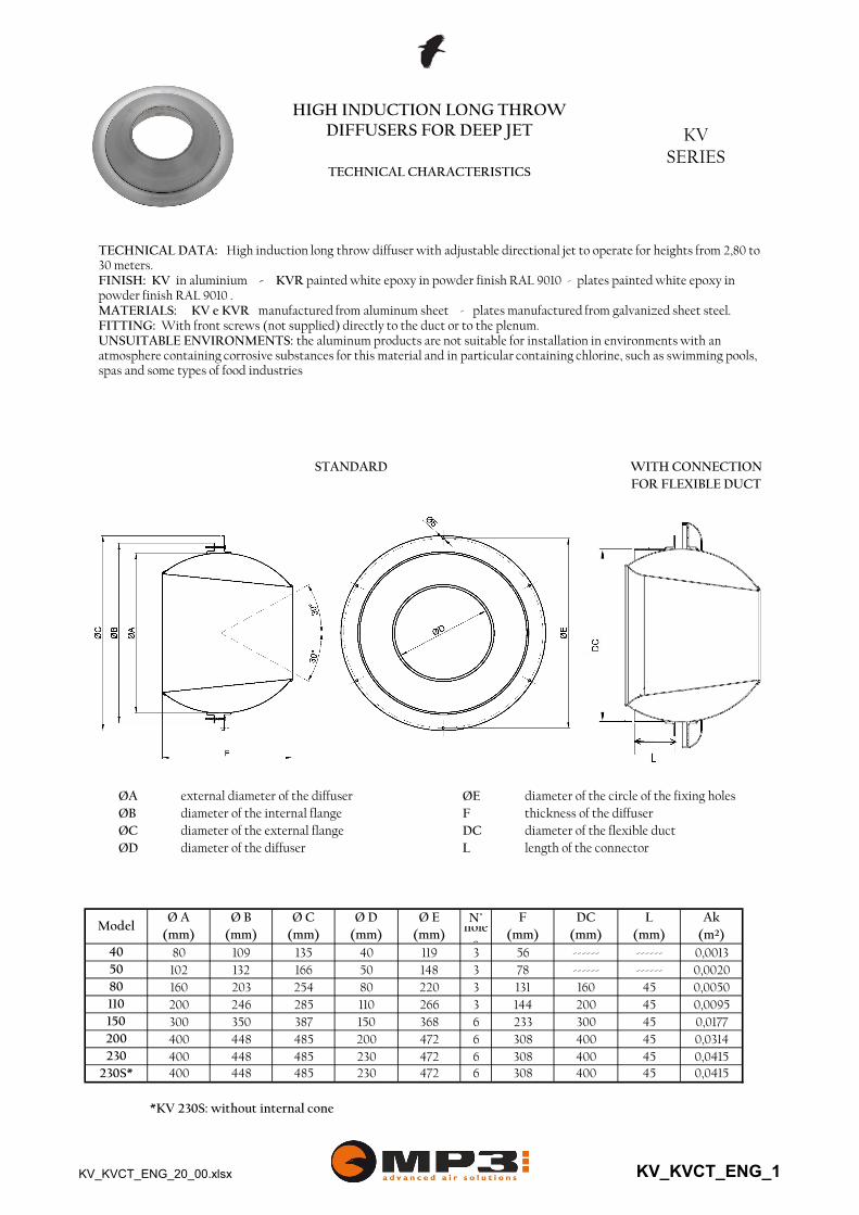
ØB diameter of the internal flange F thickness of the diffuserØC diameter of the external flange DC diameter of the flexible duct
ØA external diameter of the diffuser ØE diameter of the circle of the fixing holes
ØD diameter of the diffuser L length of the connector
ModelØ A Ø B Ø C Ø D Ø E F DC L Ak
(mm) (mm) (mm) (mm) (mm) (mm) (mm) (mm) (m²)
0,001350 102 132 166 50 148 78 ------ ------ 0,002040 80 109 135 40 119 56 ------ ------
0,0050110 200 246 285 110 266 144 200 45 0,009580 160 203 254 80 220 131 160 45
0,0177200 400 448 485 200 472 308 400 45 0,0314150 300 350 387 150 368 233 300 45
0,0415400 45 0,0415
230S* 400 448 485 230 472 308230 400 448 485 230 472 308
400 45
TECHNICAL DATA: High induction long throw diffuser with adjustable directional jet to operate for heights from 2,80 to 30 meters.FINISH: KV in aluminium - KVR painted white epoxy in powder finish RAL 9010 - plates painted white epoxy in powder finish RAL 9010 .MATERIALS: KV e KVR manufactured from aluminum sheet - plates manufactured from galvanized sheet steel.FITTING: With front screws (not supplied) directly to the duct or to the plenum.UNSUITABLE ENVIRONMENTS: the aluminum products are not suitable for installation in environments with an atmosphere containing corrosive substances for this material and in particular containing chlorine, such as swimming pools, spas and some types of food industries
KV_KVCT_ENG_20_00.xlsx KV_KVCT_ENG_1

HIGH INDUCTION LONG THROWDIFFUSERS FOR DEEP JET KV
SERIESTECHNICAL CHARACTERISTICS
Ød Diameter of the diffuserØG Diameter of the internal flange
ØD + 10 External diameter
ØI Internal diameter of the plenumØD Diameter of the circle
of the fixing holes
KV-RF040 119 40 56 22
ModelØ D
[mm]Ø d
[mm]A
[mm]F
[mm]
78 109 113 40 40 113
Ø G [mm]
I [mm]
L [mm]
C [mm]
Installationhole
[mm]
B [mm]
KV-RF080 220 80 131 57KV-RF050 148 50 78 30
158 203 210 100 60 207132 138 40 60 13698
KV-RF150 368 150 233 103KV-RF110 266 110 144 60
298 350 358 170 60 354246 251 100 60 250195
448 462 170 60 452KV-RF230 472 230 308 141KV-RF200 472 200 308 141 398
Ød Diameter of the diffuserØD1 Internal diameter of the plenumØD Diameter of the circle
398 448 462 170 60 452
of the fixing holesØD2 External diameter
Modelnr
holesØ holes [mm]
Ø D [mm]
Ø d [mm]
Ø D1 [mm]
Ø D2 [mm]
H [mm]
Ø duct min-max
[mm]
KV-RC040 3 4,2 119 40 113 129 150 160-450KV-RC050 3 4,2 148 50 138 158 150 200-500KV-RC080 3 5 220 80 210 230 200 315-630
282 300 315-800KV-RC150 6 5 368 150 358 378KV-RC110 3 5 266 110 251
300 500-800KV-RC200 6 5 472 200 462 480 350 500-1000KV-RC230 6 5 472 230 462 480 350 500-1000
KV-RFPlenum for flexible duct connection
KV-RCPlenum for circular duct connection
KV_KVCT_ENG_20_00.xlsx KV_KVCT_ENG_2

KV 40 170
HIGH INDUCTION LONG THROWDIFFUSERS FOR DEEP JET KV
SERIESTECHNICAL CHARACTERISTICS
Model I min (mm)
KV 50 210KV 80 300KV 110 350KV 150 430KV 200 550KV 230 550
ModelCover screws
flange
KV 40 KV-C40KV 50 KV-C50KV 80 KV-C80KV 110 KV-C110KV 150 KV-C150KV 200 KV-C200KV 230 KV-C230
Model F (mm)
KV 40 113KV 50 136KV 80 207
KV 230 452
KV 110 250KV 150 354KV 200 452
P30 . . . Diffusers fitted on assembly plate
KV-C COVER SCREWS FLANGE
MOUNTING ON DUCT OR WALL
KV_KVCT_ENG_20_00.xlsx KV_KVCT_ENG_3
HIGH INDUCTION LONG THROWDIFFUSERS FOR DEEP JET KV
SERIESSWIRL DEFLECTOR
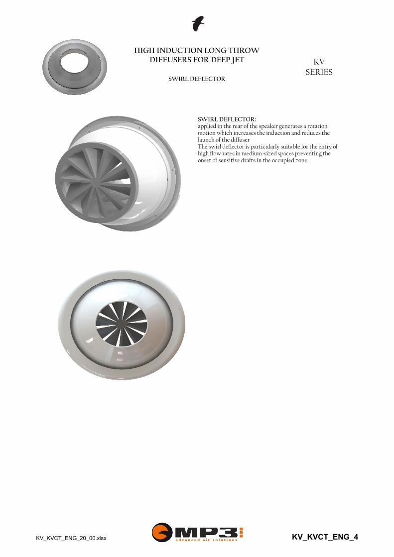
SWIRL DEFLECTOR:applied in the rear of the speaker generates a rotation motion which increases the induction and reduces the launch of the diffuserThe swirl deflector is particularly suitable for the entry of high flow rates in medium-sized spaces preventing the onset of sensitive drafts in the occupied zone.
KV_KVCT_ENG_20_00.xlsx KV_KVCT_ENG_4

A B C D
HIGH INDUCTION LONG THROWDIFFUSERS FOR DEEP JET KV-CT
SERIESAUTHOMATIC REGULATION
WITH THERMOSTATIC SPRING
Dn 80
other diameters
E F R regulation swirl[mm] [mm] damper deflector
80 80 158 200 258 204[mm] [mm] [mm] [mm] [mm]
Model
50 80 yes yes110 110 198 215 288 252 60 100 yes yes150 150 313 283 388200 200 398 283 488
452
60 150 yes yes452
60 200 yes yes60 200 yes yes
352
230 230 398 283 488
OVERVIEWThe KVCT diffuser series come equipped with a thermostatic return spring to regulate the angle of the jet.
THROW REGULATION To obtain the best heating comfort levels it is necessary to direct the flow of air downwards to eliminate the stratification of the air. Where as in cooling conditions is best to aim the flow of air towards the ceiling to eliminate the forming or air currents in the occupied zone.The KVCT diffusers automatically regulate the angle of the jet to obtain the optimal throw angle.The temperature of the injected air is in fact determines the extension or retraction of the thermostatic spring which itself determines the rotation of the jet downwards or upwards.By choosing the KVCT diffuser it is possible to eliminate:- electric thermostats;- electrical wiring system;- servomotors.The maximum range is +/- 30°. This can be limited to smaller angles, with a 5° pitch even with a different regulation for heating and cooling, by inserting and regulating stop screws on a predisposed metal plate.
The memory of the form of the spring guarantees the precise relation between the injected air and the inclination angle for an also unlimited number of cycles.
AERAULIC PERFORMANCESThe aeraulic performance of the KVCT diffusers are, in relation to the diameter, is the exact same as for those of the equivalent KV series diffuser.
KV_KVCT_ENG_20_00.xlsx KV_KVCT_ENG_5

motor
HIGH INDUCTION LONG THROWDIFFUSERS FOR DEEP JET KV
SERIESAUTHOMATIC REGULATION
WITH SERVOMOTOR
KV1
external
KV2
internal
motor
ModelA B C D E F
[mm] [mm] [mm] [mm] [mm] deflectorG H R regulation swirl
[mm] [mm] [mm] [mm] damperyes80 80 158 200 258 204 50 38 60 80 yesyes110 110 198 215 288 252 60 70 85 100 yesyes150 150 313 283 388 352 60 70 85 150 yesyes200 200 398 283 488 452 60 70 85 200 yesyes230 230 398 283 488 452 60 70 85 200 yes
THROW REGULATION To obtain the best heating comfort levels it is necessary to direct the flow of air downwards to eliminate the stratification of the air. Where as in cooling conditions is best to aim the flow of air towards the ceiling to eliminate the forming or air currents in the occupied zone.
With the diffusers KV1-KV2 series the inclination of the jet is controlled by servo motor ON / OFF or modulating to obtain the optimum launch angle. The maximum range is + / -30 °. This excursion may be limited to smaller angles with different adjustment for heating and cooling.
KV_KVCT_ENG_20_00.xlsx KV_KVCT_ENG_6
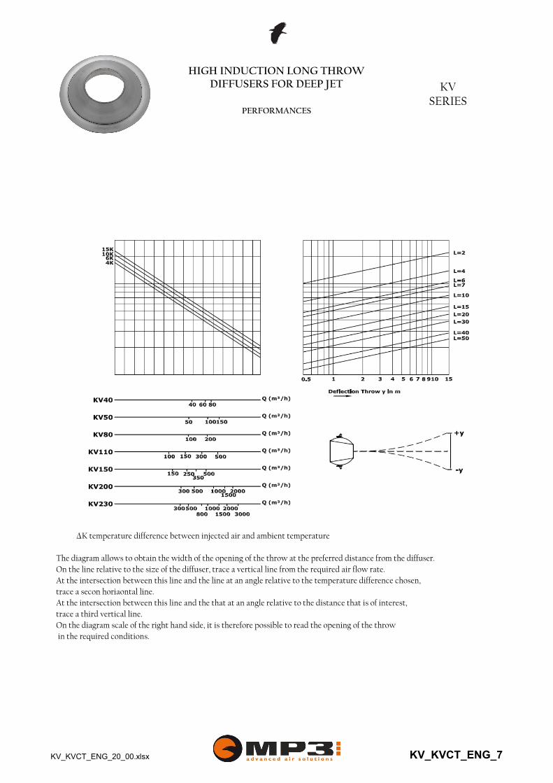
∆K temperature difference between injected air and ambient temperature
The diagram allows to obtain the width of the opening of the throw at the preferred distance from the diffuser.On the line relative to the size of the diffuser, trace a vertical line from the required air flow rate.At the intersection between this line and the line at an angle relative to the temperature difference chosen, trace a secon horiaontal line.At the intersection between this line and the that at an angle relative to the distance that is of interest, trace a third vertical line.On the diagram scale of the right hand side, it is therefore possible to read the opening of the throw in the required conditions.
HIGH INDUCTION LONG THROWDIFFUSERS FOR DEEP JET KV
SERIESPERFORMANCES
KV_KVCT_ENG_20_00.xlsx KV_KVCT_ENG_7

HIGH INDUCTION LONG THROWDIFFUSERS FOR DEEP JET KV
SERIESPERFORMANCE
KV 40
0
5
10
15
20
25
20 25 30 35 40 45 50 55 60
Lw (d
Ba)
Q (m³/h)
KV-40 Sound power
0
10
20
30
40
50
60
70
80
90
100
20 25 30 35 40 45 50 55 60
Δp
(P
a)
Q (m³/h)
KV-40 Pressure drop
0,00
0,20
0,40
0,60
0,80
1,00
1,20
5 7 9 11 13 15 17 19 21 23 25 27 29 31 33 35
Vx(
m/s
)
L (m)
KV-40 Throw
50 m³/h
40 m³/h
35 m³/h
25 m³/h
55 m³/h
Data measured in reverberation room in accordance with international standards:ISO 3741 1999: Acoustic - determination of sound power levels of noise sources using sound pressure -Precision methods for reverberation roomsISO 5135 1997: Acoustic - determination of sound power levels of noise from air-terminal devices ; air terminal units; dampers and valves by measurement in a reverberation room.The data presented does not consider the attenuation given by the area of installation. This attenuation is normally between 6 and 10 dBA and is determined by the room size, the shape of the environment and the interior features.
Data obtained from CFD mathematical model in virtual test room operating in isothermal conditions in accordance with the international standard:ISO 5219 1984: Air distribution and air diffusion - Laboratory. Aerodynamic testing and rating of air terminal devices.L (m) horizontal distance in metres from the centre of the diffuserVL (m/s) maximum speed in the air stream
KV_KVCT_ENG_20_00.xlsx KV_KVCT_ENG_8
HIGH INDUCTION LONG THROWDIFFUSERS FOR DEEP JET KV
SERIESPERFORMANCE
KV 50
0
5
10
15
20
25
30 40 50 60 70 80 90
Lw
(dB
a)
Q (m³/h)
KV-50 Sound power
0
10
20
30
40
50
60
70
80
90
100
30 40 50 60 70 80 90
Δp
(P
a)
Q (m³/h)
KV-50 Pressure drop
0,00
0,20
0,40
0,60
0,80
1,00
1,20
1,40
5 7 9 11 13 15 17 19 21 23 25 27 29 31 33 35
Vx(
m/s
)
L (m)
KV-50 Throw
75 m³/h
65 m³/h
55 m³/h
40 m³/h
85 m³/h
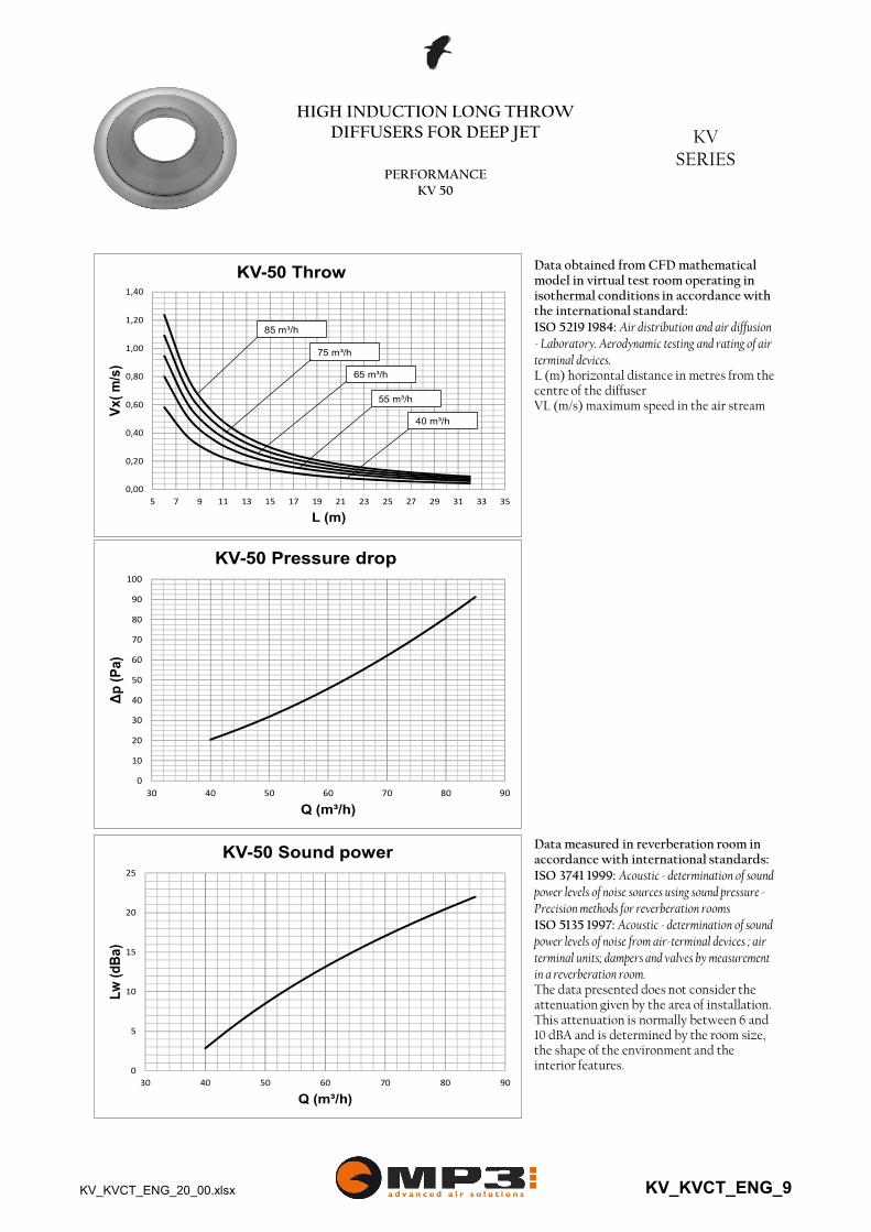
Data measured in reverberation room in accordance with international standards:ISO 3741 1999: Acoustic - determination of sound power levels of noise sources using sound pressure -Precision methods for reverberation roomsISO 5135 1997: Acoustic - determination of sound power levels of noise from air-terminal devices ; air terminal units; dampers and valves by measurement in a reverberation room.The data presented does not consider the attenuation given by the area of installation. This attenuation is normally between 6 and 10 dBA and is determined by the room size, the shape of the environment and the interior features.
Data obtained from CFD mathematical model in virtual test room operating in isothermal conditions in accordance with the international standard:ISO 5219 1984: Air distribution and air diffusion - Laboratory. Aerodynamic testing and rating of air terminal devices.L (m) horizontal distance in metres from the centre of the diffuserVL (m/s) maximum speed in the air stream
KV_KVCT_ENG_20_00.xlsx KV_KVCT_ENG_9

HIGH INDUCTION LONG THROWDIFFUSERS FOR DEEP JET KV
SERIESPERFORMANCE
KV 80
0
5
10
15
20
25
30
100 120 140 160 180 200 220
Lw
(dB
a)
Q (m³/h)
KV-80 Sound power
0
10
20
30
40
50
60
70
80
90
100
100 120 140 160 180 200 220
Δp
(P
a)
Q (m³/h)
KV-80 Pressure drop
0,00
0,20
0,40
0,60
0,80
1,00
1,20
1,40
1,60
1,80
2,00
5 7 9 11 13 15 17 19 21 23 25 27 29 31 33 35
Vx(
m/s
)
L (m)
KV-80 Throw
190 m³/h
165 m³/h
135 m³/h
110 m³/h
215 m³/h
Data measured in reverberation room in accordance with international standards:ISO 3741 1999: Acoustic - determination of sound power levels of noise sources using sound pressure -Precision methods for reverberation roomsISO 5135 1997: Acoustic - determination of sound power levels of noise from air-terminal devices ; air terminal units; dampers and valves by measurement in a reverberation room.The data presented does not consider the attenuation given by the area of installation. This attenuation is normally between 6 and 10 dBA and is determined by the room size, the shape of the environment and the interior features.
Data obtained from CFD mathematical model in virtual test room operating in isothermal conditions in accordance with the international standard:ISO 5219 1984: Air distribution and air diffusion - Laboratory. Aerodynamic testing and rating of air terminal devices.L (m) horizontal distance in metres from the centre of the diffuserVL (m/s) maximum speed in the air stream
KV_KVCT_ENG_20_00.xlsx KV_KVCT_ENG_10

HIGH INDUCTION LONG THROWDIFFUSERS FOR DEEP JET KV
SERIESPERFORMANCE
KV 80
0
5
10
15
20
25
60 70 80 90 100 110 120 130 140 150
Lw
(dB
a)
Q (m³/h)
KV-80+swirl Sound power
0
10
20
30
40
50
60
20 40 60 80 100 120 140 160
Δp
(P
a)
Q (m³/h)
KV-80+swirl Pressure drop
0,00
0,10
0,20
0,30
0,40
0,50
0,60
5 7 9 11 13 15 17 19 21
Vx(
m/s
)
L (m)
KV-80+swirl Throw
120 m³/h
90 m³/h
65 m³/h
35 m³/h
145 m³/h
Data measured in reverberation room in accordance with international standards:ISO 3741 1999: Acoustic - determination of sound power levels of noise sources using sound pressure -Precision methods for reverberation roomsISO 5135 1997: Acoustic - determination of sound power levels of noise from air-terminal devices ; air terminal units; dampers and valves by measurement in a reverberation room.The data presented does not consider the attenuation given by the area of installation. This attenuation is normally between 6 and 10 dBA and is determined by the room size, the shape of the environment and the interior features.
Data obtained from CFD mathematical model in virtual test room operating in isothermal conditions in accordance with the international standard:ISO 5219 1984: Air distribution and air diffusion - Laboratory. Aerodynamic testing and rating of air terminal devices.L (m) horizontal distance in metres from the centre of the diffuserVL (m/s) maximum speed in the air stream
KV_KVCT_ENG_20_00.xlsx KV_KVCT_ENG_11

HIGH INDUCTION LONG THROWDIFFUSERS FOR DEEP JET KV
SERIESPERFORMANCE
KV 110
0
5
10
15
20
25
30
35
200 225 250 275 300 325 350 375 400 425
Lw
(dB
a)
Q (m³/h)
KV-110 Sound power
0
10
20
30
40
50
60
70
80
90
100
200 225 250 275 300 325 350 375 400 425
Δp
(P
a)
Q (m³/h)
KV-110 Pressure drop
Data measured in reverberation room in accordance with international standards:ISO 3741 1999: Acoustic - determination of sound power levels of noise sources using sound pressure -Precision methods for reverberation roomsISO 5135 1997: Acoustic - determination of sound power levels of noise from air-terminal devices ; air terminal units; dampers and valves by measurement in a reverberation room.The data presented does not consider the attenuation given by the area of installation. This attenuation is normally between 6 and 10 dBA and is determined by the room size, the shape of the environment and the interior features.
Data obtained from CFD mathematical model in virtual test room operating in isothermal conditions in accordance with the international standard:ISO 5219 1984: Air distribution and air diffusion - Laboratory. Aerodynamic testing and rating of air terminal devices.L (m) horizontal distance in metres from the centre of the diffuserVL (m/s) maximum speed in the air stream
0,00
0,50
1,00
1,50
2,00
2,50
5 7 9 11 13 15 17 19 21 23 25 27 29 31 33 35
Vx(
m/s
)
L (m)
KV-110 Throw
360 m³/h
310 m³/h
255 m³/h
205 m³/h
410 m³/h
KV_KVCT_ENG_20_00.xlsx KV_KVCT_ENG_12
HIGH INDUCTION LONG THROWDIFFUSERS FOR DEEP JET KV
SERIESPERFORMANCE
KV 110
0
5
10
15
20
25
30
100 125 150 175 200 225 250 275 300
Lw
(dB
a)
Q (m³/h)
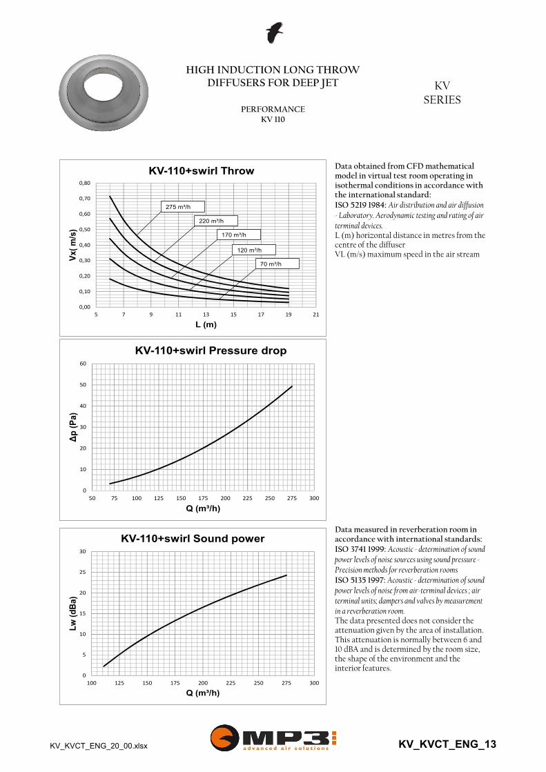
KV-110+swirl Sound power
0,00
0,10
0,20
0,30
0,40
0,50
0,60
0,70
0,80
5 7 9 11 13 15 17 19 21
Vx(
m/s
)
L (m)
KV-110+swirl Throw
220 m³/h
170 m³/h
120 m³/h
70 m³/h
275 m³/h
Data measured in reverberation room in accordance with international standards:ISO 3741 1999: Acoustic - determination of sound power levels of noise sources using sound pressure -Precision methods for reverberation roomsISO 5135 1997: Acoustic - determination of sound power levels of noise from air-terminal devices ; air terminal units; dampers and valves by measurement in a reverberation room.The data presented does not consider the attenuation given by the area of installation. This attenuation is normally between 6 and 10 dBA and is determined by the room size, the shape of the environment and the interior features.
Data obtained from CFD mathematical model in virtual test room operating in isothermal conditions in accordance with the international standard:ISO 5219 1984: Air distribution and air diffusion - Laboratory. Aerodynamic testing and rating of air terminal devices.L (m) horizontal distance in metres from the centre of the diffuserVL (m/s) maximum speed in the air stream
0
10
20
30
40
50
60
50 75 100 125 150 175 200 225 250 275 300
Δp
(P
a)
Q (m³/h)
KV-110+swirl Pressure drop
KV_KVCT_ENG_20_00.xlsx KV_KVCT_ENG_13

HIGH INDUCTION LONG THROWDIFFUSERS FOR DEEP JET KV
SERIESPERFORMANCE
KV 150
0
5
10
15
20
25
30
35
350 400 450 500 550 600 650 700 750 800
Lw
(dB
a)
Q (m³/h)
KV-150 Sound power
0
10
20
30
40
50
60
70
80
90
100
350 400 450 500 550 600 650 700 750 800
Δp
(P
a)
Q (m³/h)
KV-150 Pressure drop
0,00
0,20
0,40
0,60
0,80
1,00
1,20
1,40
1,60
1,80
2,00
5 7 9 11 13 15 17 19 21 23 25 27 29 31 33 35
Vx(
m/s
)
L (m)
KV-150 Throw
670 m³/h
575 m³/h
475 m³/h
380 m³/h
765 m³/h
Data measured in reverberation room in accordance with international standards:ISO 3741 1999: Acoustic - determination of sound power levels of noise sources using sound pressure -Precision methods for reverberation roomsISO 5135 1997: Acoustic - determination of sound power levels of noise from air-terminal devices ; air terminal units; dampers and valves by measurement in a reverberation room.The data presented does not consider the attenuation given by the area of installation. This attenuation is normally between 6 and 10 dBA and is determined by the room size, the shape of the environment and the interior features.
Data obtained from CFD mathematical model in virtual test room operating in isothermal conditions in accordance with the international standard:ISO 5219 1984: Air distribution and air diffusion - Laboratory. Aerodynamic testing and rating of air terminal devices.L (m) horizontal distance in metres from the centre of the diffuserVL (m/s) maximum speed in the air stream
KV_KVCT_ENG_20_00.xlsx KV_KVCT_ENG_14
HIGH INDUCTION LONG THROWDIFFUSERS FOR DEEP JET KV
SERIESPERFORMANCE
KV 150
0
5
10
15
20
25
30
150 200 250 300 350 400 450 500 550
Lw
(dB
a)
Q (m³/h)
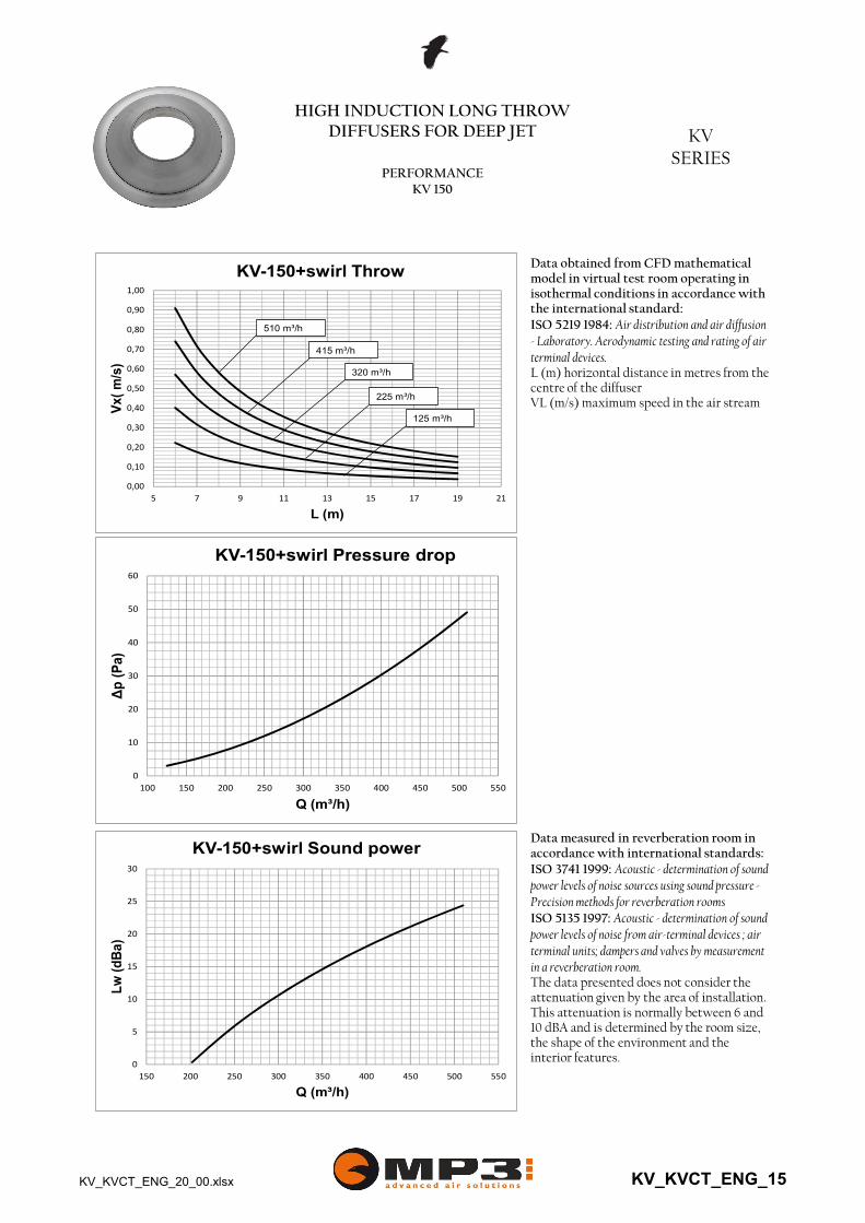
KV-150+swirl Sound power
0
10
20
30
40
50
60
100 150 200 250 300 350 400 450 500 550
Δp
(P
a)
Q (m³/h)
KV-150+swirl Pressure drop
0,00
0,10
0,20
0,30
0,40
0,50
0,60
0,70
0,80
0,90
1,00
5 7 9 11 13 15 17 19 21
Vx(
m/s
)
L (m)
KV-150+swirl Throw
415 m³/h
320 m³/h
225 m³/h
125 m³/h
510 m³/h
Data measured in reverberation room in accordance with international standards:ISO 3741 1999: Acoustic - determination of sound power levels of noise sources using sound pressure -Precision methods for reverberation roomsISO 5135 1997: Acoustic - determination of sound power levels of noise from air-terminal devices ; air terminal units; dampers and valves by measurement in a reverberation room.The data presented does not consider the attenuation given by the area of installation. This attenuation is normally between 6 and 10 dBA and is determined by the room size, the shape of the environment and the interior features.
Data obtained from CFD mathematical model in virtual test room operating in isothermal conditions in accordance with the international standard:ISO 5219 1984: Air distribution and air diffusion - Laboratory. Aerodynamic testing and rating of air terminal devices.L (m) horizontal distance in metres from the centre of the diffuserVL (m/s) maximum speed in the air stream
KV_KVCT_ENG_20_00.xlsx KV_KVCT_ENG_15

HIGH INDUCTION LONG THROWDIFFUSERS FOR DEEP JET KV
SERIESPERFORMANCE
KV 200
0
5
10
15
20
25
30
35
600 700 800 900 1000 1100 1200 1300 1400
Lw
(dB
a)
Q (m³/h)
KV-200 Sound power
0
10
20
30
40
50
60
70
80
90
100
600 700 800 900 1000 1100 1200 1300 1400
Δp
(P
a)
Q (m³/h)
KV-200 Pressure drop
0,00
0,25
0,50
0,75
1,00
1,25
1,50
1,75
2,00
2,25
2,50
5 7 9 11 13 15 17 19 21 23 25 27 29 31 33 35
Vx(
m/s
)
L (m)
KV-200 Throw
1190 m³/h
1020 m³/h
850 m³/h
680 m³/h
1355 m³/h
Data measured in reverberation room in accordance with international standards:ISO 3741 1999: Acoustic - determination of sound power levels of noise sources using sound pressure -Precision methods for reverberation roomsISO 5135 1997: Acoustic - determination of sound power levels of noise from air-terminal devices ; air terminal units; dampers and valves by measurement in a reverberation room.The data presented does not consider the attenuation given by the area of installation. This attenuation is normally between 6 and 10 dBA and is determined by the room size, the shape of the environment and the interior features.
Data obtained from CFD mathematical model in virtual test room operating in isothermal conditions in accordance with the international standard:ISO 5219 1984: Air distribution and air diffusion - Laboratory. Aerodynamic testing and rating of air terminal devices.L (m) horizontal distance in metres from the centre of the diffuserVL (m/s) maximum speed in the air stream
KV_KVCT_ENG_20_00.xlsx KV_KVCT_ENG_16

HIGH INDUCTION LONG THROWDIFFUSERS FOR DEEP JET KV
SERIESPERFORMANCE
KV 200
0
5
10
15
20
25
400 500 600 700 800 900 1000
Lw
(dB
a)
Q (m³/h)
KV-200+swirl Sound power
0,00
0,20
0,40
0,60
0,80
1,00
1,20
5 7 9 11 13 15 17 19 21
Vx(
m/s
)
L (m)
KV-200+swirl Throw
735 m³/h
565 m³/h
395 m³/h
225 m³/h
905 m³/h
Data measured in reverberation room in accordance with international standards:ISO 3741 1999: Acoustic - determination of sound power levels of noise sources using sound pressure -Precision methods for reverberation roomsISO 5135 1997: Acoustic - determination of sound power levels of noise from air-terminal devices ; air terminal units; dampers and valves by measurement in a reverberation room.The data presented does not consider the attenuation given by the area of installation. This attenuation is normally between 6 and 10 dBA and is determined by the room size, the shape of the environment and the interior features.
Data obtained from CFD mathematical model in virtual test room operating in isothermal conditions in accordance with the international standard:ISO 5219 1984: Air distribution and air diffusion - Laboratory. Aerodynamic testing and rating of air terminal devices.L (m) horizontal distance in metres from the centre of the diffuserVL (m/s) maximum speed in the air stream
0
10
20
30
40
50
60
200 300 400 500 600 700 800 900 1000
Δp
(P
a)
Q (m³/h)
KV-200+swirl Pressure drop
KV_KVCT_ENG_20_00.xlsx KV_KVCT_ENG_17

HIGH INDUCTION LONG THROWDIFFUSERS FOR DEEP JET KV
SERIESPERFORMANCE
KV 230
0
5
10
15
20
25
30
35
40
800 950 1100 1250 1400 1550 1700 1850
Lw
(dB
a)
Q (m³/h)
KV-230 Sound power
0
10
20
30
40
50
60
70
80
90
100
800 950 1100 1250 1400 1550 1700 1850
Δp
(P
a)
Q (m³/h)
KV-230 Pressure drop
0,00
0,25
0,50
0,75
1,00
1,25
1,50
1,75
2,00
2,25
2,50
2,75
5 7 9 11 13 15 17 19 21 23 25 27 29 31 33 35
Vx(
m/s
)
L (m)
KV-230 Throw
1570 m³/h
1345 m³/h
1120 m³/h
895 m³/h
1795 m³/h
Data measured in reverberation room in accordance with international standards:ISO 3741 1999: Acoustic - determination of sound power levels of noise sources using sound pressure -Precision methods for reverberation roomsISO 5135 1997: Acoustic - determination of sound power levels of noise from air-terminal devices ; air terminal units; dampers and valves by measurement in a reverberation room.The data presented does not consider the attenuation given by the area of installation. This attenuation is normally between 6 and 10 dBA and is determined by the room size, the shape of the environment and the interior features.
Data obtained from CFD mathematical model in virtual test room operating in isothermal conditions in accordance with the international standard:ISO 5219 1984: Air distribution and air diffusion - Laboratory. Aerodynamic testing and rating of air terminal devices.L (m) horizontal distance in metres from the centre of the diffuserVL (m/s) maximum speed in the air stream
KV_KVCT_ENG_20_00.xlsx KV_KVCT_ENG_18
HIGH INDUCTION LONG THROWDIFFUSERS FOR DEEP JET KV
SERIESPERFORMANCE
KV 230
0
5
10
15
20
25
30
500 600 700 800 900 1000 1100 1200 1300
Lw
(dB
a)
Q (m³/h)
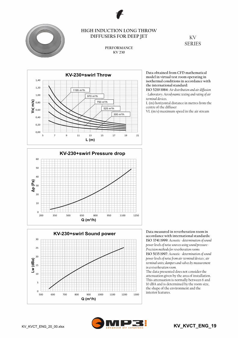
KV-230+swirl Sound power
0
10
20
30
40
50
60
200 350 500 650 800 950 1100 1250
Δp
(P
a)
Q (m³/h)
KV-230+swirl Pressure drop
Data measured in reverberation room in accordance with international standards:ISO 3741 1999: Acoustic - determination of sound power levels of noise sources using sound pressure -Precision methods for reverberation roomsISO 5135 1997: Acoustic - determination of sound power levels of noise from air-terminal devices ; air terminal units; dampers and valves by measurement in a reverberation room.The data presented does not consider the attenuation given by the area of installation. This attenuation is normally between 6 and 10 dBA and is determined by the room size, the shape of the environment and the interior features.
Data obtained from CFD mathematical model in virtual test room operating in isothermal conditions in accordance with the international standard:ISO 5219 1984: Air distribution and air diffusion - Laboratory. Aerodynamic testing and rating of air terminal devices.L (m) horizontal distance in metres from the centre of the diffuserVL (m/s) maximum speed in the air stream
0,00
0,20
0,40
0,60
0,80
1,00
1,20
1,40
5 7 9 11 13 15 17 19 21
Vx(
m/s
)
L (m)
KV-230+swirl Throw
970 m³/h
750 m³/h
525 m³/h
300 m³/h
1195 m³/h
KV_KVCT_ENG_20_00.xlsx KV_KVCT_ENG_19
HIGH INDUCTION LONG THROWDIFFUSERS FOR DEEP JET KV
SERIESPERFORMANCE
KV 230S
0
10
20
30
40
50
60
800 950 1100 1250 1400 1550 1700 1850
Lw
(dB
a)
Q (m³/h)
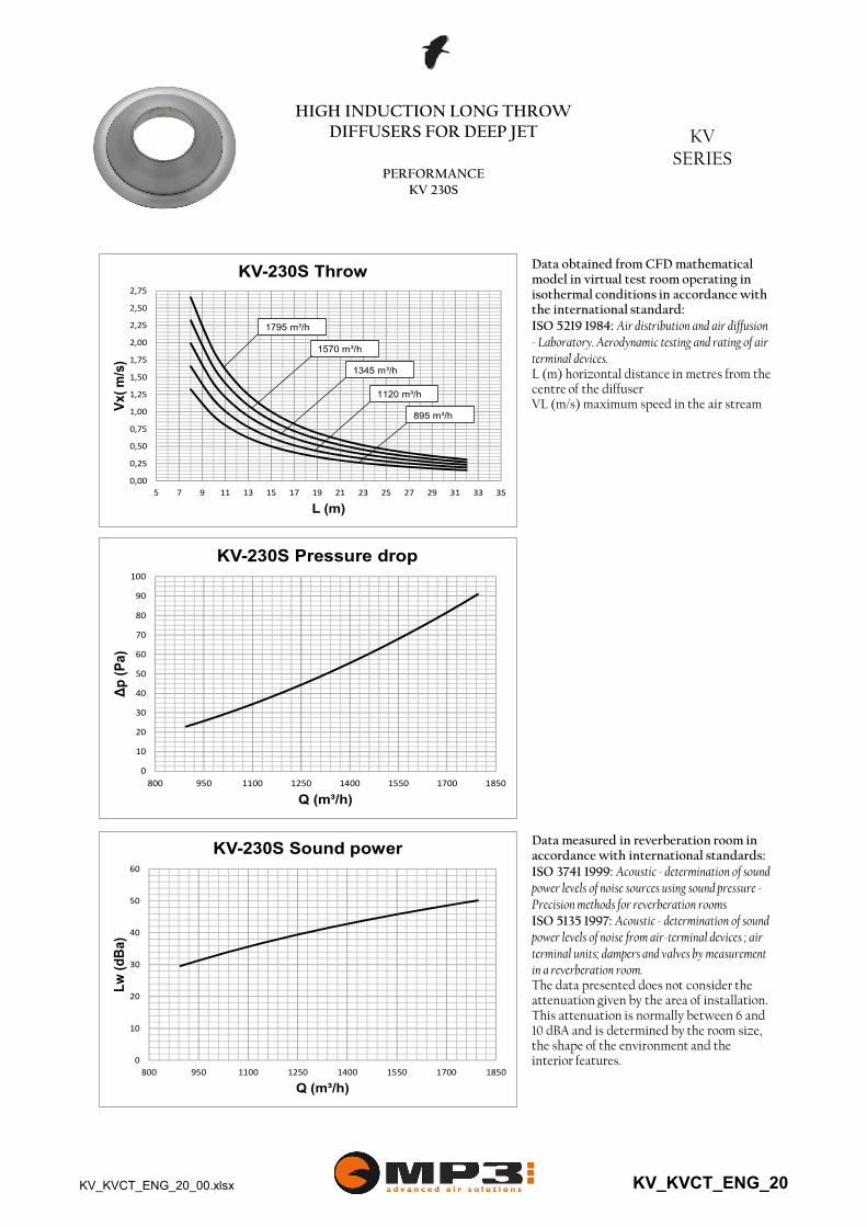
KV-230S Sound power
0
10
20
30
40
50
60
70
80
90
100
800 950 1100 1250 1400 1550 1700 1850
Δp
(P
a)
Q (m³/h)
KV-230S Pressure drop
0,00
0,25
0,50
0,75
1,00
1,25
1,50
1,75
2,00
2,25
2,50
2,75
5 7 9 11 13 15 17 19 21 23 25 27 29 31 33 35
Vx(
m/s
)
L (m)
KV-230S Throw
1570 m³/h
1345 m³/h
1120 m³/h
895 m³/h
1795 m³/h
Data measured in reverberation room in accordance with international standards:ISO 3741 1999: Acoustic - determination of sound power levels of noise sources using sound pressure -Precision methods for reverberation roomsISO 5135 1997: Acoustic - determination of sound power levels of noise from air-terminal devices ; air terminal units; dampers and valves by measurement in a reverberation room.The data presented does not consider the attenuation given by the area of installation. This attenuation is normally between 6 and 10 dBA and is determined by the room size, the shape of the environment and the interior features.
Data obtained from CFD mathematical model in virtual test room operating in isothermal conditions in accordance with the international standard:ISO 5219 1984: Air distribution and air diffusion - Laboratory. Aerodynamic testing and rating of air terminal devices.L (m) horizontal distance in metres from the centre of the diffuserVL (m/s) maximum speed in the air stream
KV_KVCT_ENG_20_00.xlsx KV_KVCT_ENG_20

HIGH INDUCTION LONG THROWDIFFUSERS FOR DEEP JET KV
SERIESPERFORMANCE
KV 230S
0
5
10
15
20
25
30
35
40
45
300 450 600 750 900 1050 1200 1350
Lw
(dB
a)
Q (m³/h)
KV-230S+swirl Sound power
0
10
20
30
40
50
60
200 350 500 650 800 950 1100 1250
Δp
(P
a)
Q (m³/h)
KV-230S+swirl Pressure drop
0,00
0,20
0,40
0,60
0,80
1,00
1,20
1,40
5 7 9 11 13 15 17 19 21
Vx(
m/s
)
L (m)
KV-230S+swirl Throw
970 m³/h
750 m³/h
525 m³/h
300 m³/h
1195 m³/h
Data measured in reverberation room in accordance with international standards:ISO 3741 1999: Acoustic - determination of sound power levels of noise sources using sound pressure -Precision methods for reverberation roomsISO 5135 1997: Acoustic - determination of sound power levels of noise from air-terminal devices ; air terminal units; dampers and valves by measurement in a reverberation room.The data presented does not consider the attenuation given by the area of installation. This attenuation is normally between 6 and 10 dBA and is determined by the room size, the shape of the environment and the interior features.
Data obtained from CFD mathematical model in virtual test room operating in isothermal conditions in accordance with the international standard:ISO 5219 1984: Air distribution and air diffusion - Laboratory. Aerodynamic testing and rating of air terminal devices.L (m) horizontal distance in metres from the centre of the diffuserVL (m/s) maximum speed in the air stream
KV_KVCT_ENG_20_00.xlsx KV_KVCT_ENG_21
--
12
CT
--R
--S
--S
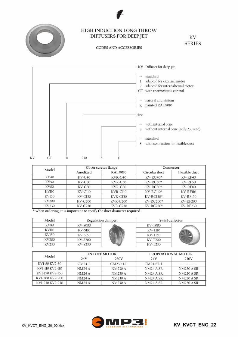
* when ordering, it is important to speify the duct diameter required
adapted for external motoradapted for internalternal motorwith thermostatic control
natural alluminiumpainted RAL 9010
size
HIGH INDUCTION LONG THROWDIFFUSERS FOR DEEP JET KV
SERIESCODES AND ACCESSORIES
KV Diffuser for deep jet
standard
ModelCover screws flange Connector
Anodized RAL 9010 Circular duct Flexible duct
with internal conewithout internal cone (only 230 size)
standardwith connection for flexible duct
KV CT R 230 S F
KV40 KV-C40 KVR-C40 KV-RC40* KV-RF40KV50 KV-C50 KVR-C50 KV-RC50* KV-RF50KV80 KV-C80 KVR-C80 KV-RC80* KV-RF80KV110 KV-C110 KVR-C110 KV-RC110* KV-RF110
KV230 KV-C230 KVR-C230 KV-RC230* KV-RF230
Model Regulation damper Swirl deflector
KV150 KV-C150 KVR-C150 KV-RC150* KV-RF150KV200 KV-C200 KVR-C200 KV-RC200* KV-RF200
KV150 KV-S150 KV-T150KV200 KV-S200 KV-T200
KV80 KV-S080 KV-T080KV110 KV-S110 KV-T110
KV230 KV-S230 KV-T230
ModelON / OFF MOTOR PROPORTIONAL MOTOR
24V 230V 24V 230V
KV1-80 KV2-80 CM24-L CM230-1-L CM24-SR-L --------------KV1-110 KV2-110 NM24 A NM230 A NM24 A SR NM230 A SR
KV1-230 KV2-230 NM24 A NM230 A NM24 A SR NM230 A SR
KV1-150 KV2-150 NM24 A NM230 A NM24 A SR NM230 A SRKV1-200 KV2-200 NM24 A NM230 A NM24 A SR NM230 A SR
KV_KVCT_ENG_20_00.xlsx KV_KVCT_ENG_22