high frequency connectors: n 18 ghz tnc 18 ghz/sma …
TRANSCRIPT

SIMPLIFICATION IS OUR INNOVATON Visit www.radiall.com for more information
SECTION 10
HIGH FREQUENCY CONNECTORS: N 18 GHZTNC 18 GHZ/SMA 2.9/2.4 MM
R163/R143/R127/R327

10-3Go online for data sheets & assembly instructions. Visit www.radiall.com and enter the part number.
SIMPLIFICATION IS OUR INNOVATION
N 18 GHz
Introduction . . . . . . . . . . . . . . . . . . . . . . . . . . . . . . . . . . . . . . . . . . . . . . . . . . . . . . . . . . . . . . . . . . . . . . . . . . . . . . . . . . . . . . . . . . . . . . . . . . . . . . . . . . . . 10-4 to 10-5 Interface . . . . . . . . . . . . . . . . . . . . . . . . . . . . . . . . . . . . . . . . . . . . . . . . . . . . . . . . . . . . . . . . . . . . . . . . . . . . . . . . . . . . . . . . . . . . . . . . . . . . . . . . . . . . . . . . . . . . . . . . 10-6Characteristics . . . . . . . . . . . . . . . . . . . . . . . . . . . . . . . . . . . . . . . . . . . . . . . . . . . . . . . . . . . . . . . . . . . . . . . . . . . . . . . . . . . . . . . . . . . . . . . . . . . . . . . . . . . . . . . . . 10-7Plugs and jacks . . . . . . . . . . . . . . . . . . . . . . . . . . . . . . . . . . . . . . . . . . . . . . . . . . . . . . . . . . . . . . . . . . . . . . . . . . . . . . . . . . . . . . . . . . . . . . . . . . . . . . . . . . . . . . . . . 10-8Adapters . . . . . . . . . . . . . . . . . . . . . . . . . . . . . . . . . . . . . . . . . . . . . . . . . . . . . . . . . . . . . . . . . . . . . . . . . . . . . . . . . . . . . . . . . . . . . . . . . . . . . . . . . . . . . . . . . . . . . . . . 10-8
TNC 18 GHz
Interface . . . . . . . . . . . . . . . . . . . . . . . . . . . . . . . . . . . . . . . . . . . . . . . . . . . . . . . . . . . . . . . . . . . . . . . . . . . . . . . . . . . . . . . . . . . . . . . . . . . . . . . . . . . . . . . . . . . . . . . . 10-9Characteristics . . . . . . . . . . . . . . . . . . . . . . . . . . . . . . . . . . . . . . . . . . . . . . . . . . . . . . . . . . . . . . . . . . . . . . . . . . . . . . . . . . . . . . . . . . . . . . . . . . . . . . . . . . . . . . .10-10Plugs . . . . . . . . . . . . . . . . . . . . . . . . . . . . . . . . . . . . . . . . . . . . . . . . . . . . . . . . . . . . . . . . . . . . . . . . . . . . . . . . . . . . . . . . . . . . . . . . . . . . . . . . . . . . . . . . . . . . . . . . . . . 10-11Jacks . . . . . . . . . . . . . . . . . . . . . . . . . . . . . . . . . . . . . . . . . . . . . . . . . . . . . . . . . . . . . . . . . . . . . . . . . . . . . . . . . . . . . . . . . . . . . . . . . . . . . . . . . . . . . . . . .10-11 to 10-12Receptacles . . . . . . . . . . . . . . . . . . . . . . . . . . . . . . . . . . . . . . . . . . . . . . . . . . . . . . . . . . . . . . . . . . . . . . . . . . . . . . . . . . . . . . . . . . . . . . . . . . . . . . . . . . . . . . . . . . . . 10-12Adapters . . . . . . . . . . . . . . . . . . . . . . . . . . . . . . . . . . . . . . . . . . . . . . . . . . . . . . . . . . . . . . . . . . . . . . . . . . . . . . . . . . . . . . . . . . . . . . . . . . . . . . . . . . . . . . . . . . . . . . . 10-13Caps . . . . . . . . . . . . . . . . . . . . . . . . . . . . . . . . . . . . . . . . . . . . . . . . . . . . . . . . . . . . . . . . . . . . . . . . . . . . . . . . . . . . . . . . . . . . . . . . . . . . . . . . . . . . . . . . . . . . . . . . . . . . 10-13
SMA 2.9
Introduction . . . . . . . . . . . . . . . . . . . . . . . . . . . . . . . . . . . . . . . . . . . . . . . . . . . . . . . . . . . . . . . . . . . . . . . . . . . . . . . . . . . . . . . . . . . . . . . . . . . . . . . . . . . . . . . . . . . . 10-14Interface . . . . . . . . . . . . . . . . . . . . . . . . . . . . . . . . . . . . . . . . . . . . . . . . . . . . . . . . . . . . . . . . . . . . . . . . . . . . . . . . . . . . . . . . . . . . . . . . . . . . . . . . . . . . . . . . . . . . . . . 10-15Characteristics and plugs . . . . . . . . . . . . . . . . . . . . . . . . . . . . . . . . . . . . . . . . . . . . . . . . . . . . . . . . . . . . . . . . . . . . . . . . . . . . . . . . . . . . . . . . . . . . . . . . . . . . 10-16Jacks and receptacles . . . . . . . . . . . . . . . . . . . . . . . . . . . . . . . . . . . . . . . . . . . . . . . . . . . . . . . . . . . . . . . . . . . . . . . . . . . . . . . . . . . . . . . . . . . . . . . . . . . . . . . . 10-17Glass bead . . . . . . . . . . . . . . . . . . . . . . . . . . . . . . . . . . . . . . . . . . . . . . . . . . . . . . . . . . . . . . . . . . . . . . . . . . . . . . . . . . . . . . . . . . . . . . . . . . . . . . . . . . . . . . . . . . . . . 10-18In series adapters . . . . . . . . . . . . . . . . . . . . . . . . . . . . . . . . . . . . . . . . . . . . . . . . . . . . . . . . . . . . . . . . . . . . . . . . . . . . . . . . . . . . . . . . . . . . . . . . . . . . . . . . . . . . . 10-18Between series adapters . . . . . . . . . . . . . . . . . . . . . . . . . . . . . . . . . . . . . . . . . . . . . . . . . . . . . . . . . . . . . . . . . . . . . . . . . . . . . . . . . . . . . . . . . . . . . . . . . . . . . 10-19Panel drilling . . . . . . . . . . . . . . . . . . . . . . . . . . . . . . . . . . . . . . . . . . . . . . . . . . . . . . . . . . . . . . . . . . . . . . . . . . . . . . . . . . . . . . . . . . . . . . . . . . . . . . . . . . . . . . . . . . 10-19
2.4 MM
Interface . . . . . . . . . . . . . . . . . . . . . . . . . . . . . . . . . . . . . . . . . . . . . . . . . . . . . . . . . . . . . . . . . . . . . . . . . . . . . . . . . . . . . . . . . . . . . . . . . . . . . . . . . . . . . . . . . . . . . . . 10-20Characteristics . . . . . . . . . . . . . . . . . . . . . . . . . . . . . . . . . . . . . . . . . . . . . . . . . . . . . . . . . . . . . . . . . . . . . . . . . . . . . . . . . . . . . . . . . . . . . . . . . . . . . . . . . . . . . . . . 10-21Plugs, jacks and receptacles . . . . . . . . . . . . . . . . . . . . . . . . . . . . . . . . . . . . . . . . . . . . . . . . . . . . . . . . . . . . . . . . . . . . . . . . . . . . . . . . . . . . . . .10-22 to 10-23Glass bead . . . . . . . . . . . . . . . . . . . . . . . . . . . . . . . . . . . . . . . . . . . . . . . . . . . . . . . . . . . . . . . . . . . . . . . . . . . . . . . . . . . . . . . . . . . . . . . . . . . . . . . . . . . . . . . . . . . . . 10-23In series adapters . . . . . . . . . . . . . . . . . . . . . . . . . . . . . . . . . . . . . . . . . . . . . . . . . . . . . . . . . . . . . . . . . . . . . . . . . . . . . . . . . . . . . . . . . . . . . . . . . . . . . . . . . . . . . 10-24Panel drilling . . . . . . . . . . . . . . . . . . . . . . . . . . . . . . . . . . . . . . . . . . . . . . . . . . . . . . . . . . . . . . . . . . . . . . . . . . . . . . . . . . . . . . . . . . . . . . . . . . . . . . . . . . . . . . . . . . 10-24
Contents
SECT
ION
10 T
ABL
E O
F CO
NTE
NTS

10-4 Go online for data sheets & assembly instructions. Visit www.radiall.com and enter the part number.
SIMPLIFICATION IS OUR INNOVATION
TYPE N 18 DESIGN FEATURES:• Excellent performance up to 18 GHz• Low VSWR and insertion loss• Highly robust construction for reliability• Superior interface environmental seal• High power capability
N 18 connectors are 50 ohm precision N Type connectors designed to perform through 18 GHz. N connectors are a popular medium sized option commonly used in microwave and RF applications that require high power handling and good electrical performance. Radiall Type N connector interfaces utilizes a PTFE (Teflon) dielectric. The male connectors are provided with a 19 mm (3/4 in.) hex coupling nut so they can be properly torqued. Connector bodies are made from stainless steel, and contacts are made from gold plated and heat treated beryllium copper contacts to insure long life and reliability. Radiall offers N connectors for semi-rigid and low loss flexible cables, receptacles and precision adapters. Connectors for low loss flexible cables and TestPro cables are not detailed in this section. They are available in our cable assembly offer.
Introduction
N 18
GH
z

10-5Go online for data sheets & assembly instructions. Visit www.radiall.com and enter the part number.
SIMPLIFICATION IS OUR INNOVATION
PLUG JACK
Interface
IMPORTANT: the 50Ω and the 75Ω connectors are NOT INTERMATEABLE, results in the interface destruction.
mm inch 0.29 .01141.25 .0493.02 .11893.06 .12044.00 .1574.20 .1654.50 .1775.00 .1975.28 .2085.40 .21266.98 .27487.02 .27648.00 .3158.02 .316
10.60 .41710.76 .42316.30 .64216.40 .64618.80 .74019.00 .748
mm inch 0.51 .0201.01 .03971.20 .04721.95 .07673.02 .11893.06 .12044.60 .18115.10 .2015.14 .2025.26 .2076.98 .27487.02 .27648.05 .3178.10 .3198.53 .3368.73 .34379.07 .3579.17 .361
11.23 .44215.85 .624
Mating dimensions are MIL-C-39012 nominal with tighter tolerances and solid outer contact.
N 18
GH
z
10-6 Go online for data sheets & assembly instructions. Visit www.radiall.com and enter the part number.
SIMPLIFICATION IS OUR INNOVATION
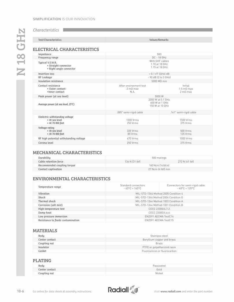
Test/Characteristics Values/Remarks
ELECTRICAL CHARACTERISTICS Impedance 50ΩFrequency range DC - 18 GHz
Typical V.S.W.R. • Straight connector• Right angle connector
With SHF cables1.10 at 18 GHz1.15 at 18 GHz
Insertion loss < 0.1 √F (GHz) dBRF Leakage - 90 dB (2 to 3 GHz)Insulation resistance 5000 MΩ min
Contact resistance• Outer contact•Inner contact
After environment test2 mΩ max
N.A.
Initial1.5 mΩ max2 mΩ max
Peak power (at sea level) 5000 W
Average power (at sea level, 25°C)
2000 W at 0.1 GHz600 W at 1 GHz
150 W at 10 GHz
.085" semi-rigid cable .141" semi-rigid cable
Dielectric withstanding voltage• At sea level • At 70 000 feet
1000 Vrms250 Vrms
1500 Vrms375 Vrms
Voltage rating• At sea level • At 70 000 feet
335 Vrms85 Vrms
500 Vrms125 Vrms
RF high potential withstanding voltage 670 Vrms 1000 Vrms
Corona level 250 Vrms 375 Vrms
MECHANICAL CHARACTERISTICSDurability 500 matingsCable retention force 136 N (31 Ibf) 272 N (61 Ibf)Recommended coupling torque 160 Ncm (14 Ibf.in)Contact captivation 27 Ncm (6 Ibf) min
ENVIRONMENTAL CHARACTERISTICSTemperature range
Standard connectors - 65°C + 165°C
Connectors for semi-rigid cable - 40°C + 125°C
Vibration MIL-STD-1344 Method 2005 Condition 4Shock MIL-STD-1344 Method 2004 Condition GThermal shock MIL-STD-1344 Method 1003 Condition ACorrosion (salt mist) MIL-STD-1344 Method 1001 Condition BHigh temperature test CECC 22000/4.7.2Damp heat CECC 22000/4.6.6Low pressure immersion EN2591 AECMA TestC14Resistance to fluids contamination EN2591 AECMA TestC15
MATERIALS Body Stainless steelCenter contact Beryllium copper and brassCoupling nut BrassInsulator PTFE or polyetherimid resinGasket Fluorosilicon or fluorocarbon
PLATINGBody PassivatedCenter contact GoldCoupling nut Nickel
Characteristics
N 18
GH
z

10-7Go online for data sheets & assembly instructions. Visit www.radiall.com and enter the part number.
SIMPLIFICATION IS OUR INNOVATION
Note: 7mm air line adapters also available upon request.
STRAIGHT PLUGS FOR SEMI-RIGID CABLES
BULKHEAD STRAIGHT JACKS, FOR SEMI-RIGID CABLES (panel sealed)
IN SERIES ADAPTERS
Cable group Cable groupdia. Part number Captive center
contact Material Note
RG402 .141" 4000-1563-009Yes Stainless steel Direct solder
RG405 .085" 4000-1563-010 Note: N18 GHz plugs for SHF high frequency flexible cable are available as cable assemblies only. Consult us for standard N18 GHz cable assembly part numbers.
Part number Fig. Dimension (mm) Note
R163 703 001 1 53.5 (2.106) Male - MaleR163 705 001 2 44.5 (1.752) Female - FemaleR163 708 001 3 46.7 (1.838) Male - Female
Cable group Cable groupdia. Part number Captive center
contactPanel
drilling Material Note
RG405 .085" 4501-9543-010Yes P14 Stainless steel Solder clamp /
Rear mountRG402 .141"4501-9543-009R163 337 001
Plugs, Jacks and Adapters
Fig. 1Fig. 2
N 18
GH
zFig. 3

10-8 Go online for data sheets & assembly instructions. Visit www.radiall.com and enter the part number.
SIMPLIFICATION IS OUR INNOVATION
TNC 18 DESIGN FEATURES• Excellent performance up to 18 GHz• Low VSWR and insertion loss• Rugged construction for reliability• Superior interface environmental seal• Medium power capability
Radiall offers TNC connectors for semi-rigid and low loss flexible cables, receptacles and precision adapters. Connectors for low loss flexible cables and TestPro cables are not detailed in this section. They are available in our cable assembly offer.
Introduction
TNC
18 G
Hz
Interface
Letter mm inch
min. max. min. max. A 6.18 6.22 0.243 0.245B 8.03 8.09 0.316 0.319C 11.40 11.60 0.449 0.457D 1.34 1.36 0.053 0.054E 0.35 0.65 0.014 0.026F 1.62 1.66 0.064 0.065G 5.28 5.32 0.208 0.2101 5.28 5.38 0.208 0.2122 5.35 5.50 0.211 0.2173 -0.30 0.55 -0.012 0.0224 0.35 0.90 0.014 0.065
Letter mm inch
min. max. min. max. A 4.68 4.72 0.184 0.186B 8.10 8.15 0.319 0.321C 8.32 8.46 0.328 0.333D 9.61 9.68 0.379 0.381E 6.93 6.98 0.273 0.275F 5.28 5.32 0.208 0.210G 1.62 1.66 0.064 0.065H 2.14 2.18 0.084 0.0861 4.98 5.23 0.196 0.2062 8.36 8.46 0.329 0.3333 0.48 1.02 0.019 0.0404 1.80 2.20 0.071 0.0875 10.60 11.00 0.417 0.4326 5.18 5.28 0.204 0.2087 -0.10 0.05 0.004 0.0028 5.20 5.70 0.204 0.224
PLUG JACK
TNC 18 connectors are 50 ohm precision TNC Type connectors designed to perform through 18 GHz. TNC connectors are a popular medium sized option commonly used in microwave and RF applications that require average power handling and good electrical performance. Radiall TNC connector interfaces utilizes a PTFE (Teflon) dielectric. The male connectors are provided with a 14 mm (9/16 in.) hex coupling nut so they can be properly torqued. Connector bodies are made from stainless steel, and contacts are made from gold plated and heat treated beryllium copper contacts to insure long life and reliability.

10-9Go online for data sheets & assembly instructions. Visit www.radiall.com and enter the part number.
SIMPLIFICATION IS OUR INNOVATION
ELECTRICAL CHARACTERISTICS Impedance - 50ΩFrequency range - DC - 18 GHz
V.S.W.R. 3-14Semi–rigid cable: 1.17 max
Flexible cable: 1.35 at 12.4 GHz In series adapter: 1.35 maxInsertion loss 3-27 0.18 dB max at 9 GHzRF leakage 3-26 -60 dB min from 2 to 3 GHzInsulation resistance 3-11 5000 MΩ min
Contact resistance • Center contact (mΩ)• Outer contact (mΩ)
3-16--
Initial1.50.2
After proof2-
Working voltage At sea level: 500 V rms at 70000 ft (21000 m): 125 V rmsDielectric withstanding voltage 3-17 At sea level: 1500 V rms at 70000 ft (21000 m): 375 V rmsRF withstanding voltage 3-23 At sea level: 1000 V rms (5 MHz sine wave)
MECHANICAL CHARACTERISTICSDurability 3-15 500 matings
Mating / unmating - axial force: not applicabletorque: 1.96 inch pounds (22.6 N.cm)
Recommended mating torque - 22.98 inch pounds (265 N.cm)Proof torque - 29.40 inch pounds (339 N.cm)Coupling mechanism retention force 3-25 100 Lbf (44.5 daN)
Cabling retention force 3-2451 Lbf (227 N min) (cable dia. .189 (4.8) to .228 (5.8))
76.4 Lbf (340 N min) (cable dia. .250 (6.35) and above)Center contact retention - Axial: 6.06 Lbf (27 N)
ENVIRONMENTAL CHARACTERISTICSTemperature range
• Standard models• Hermetic sealed models• Models for semi-rigid cables
---
-65°C / + 165°C-65°C / +100°C-65°C / +105°C
Combined climate testsThermal shock 3-20 MIL-STD-202, method 107, condition BHigh temperature endurance - MIL-STD-202, method 108Corrosion (salt spray) 3-13 MIL-STD-202, method 101, condition BVibrations 3-18 MIL-STD-202, method 204, condition BShocks 3-19 MIL-STD-202, method 213, condition GMoisture resistance 3-21 MIL-STD-202, method 106Low pressure 3-22 Not applicable
Hermetic seal - Applied vacuum 10-6 mm of Hg (Torrs)Leakage rate < 10-6 atm/cm3/s
Leakage - Pressure 3.5 bars; duration 2 mn; temperature 15°C to 25°C
MATERIALS Body - Stainless steel
Center socket contact• Male • Female
-
BrassBronze
Ferrules - BrassInsulators - PTFE teflonGaskets - Silicone elastomer
PLATING Body - PassivatedCenter contacts - Gold plated
Test / Characteristics MIL-C-39012 A Values / Remarks
Characteristics
TNC
18 G
Hz

10-10 Go online for data sheets & assembly instructions. Visit www.radiall.com and enter the part number.
SIMPLIFICATION IS OUR INNOVATION
Plugs and Jacks
TNC
18 G
Hz
All dimensions are given in mm (inch)Standard packaging = unit
STRAIGHT PLUGS CRIMP TYPE FOR FLEXIBLE CABLE
Cable group Cable group dia. Part number Fig.Dimensions mm (inch)
NoteA B C
RG142 / RG223 / RG400 5/50/DR143 082 700 1 30 (1.181) 3.2 (.126) 5.5 (.218)
Incl. heatshrink
tube
R143 097 700
2
43.5 (1.713) 3 (.118) 5.5 (.218)- 3.85/50/S R143 088 101 47 (1.85) 3 (.118) 4.2 (.165)- 4.13/50 R143 093 700 43.5 (1.71) 2.7 (.106) 4.5 (.177)- 8.07/50/S R143 092 790 49.7 (1.957) 6.3 (.248) 8.4 (.331)
RG214 / RG225 11/50/D R143 089 700 1 35 (1.38) 7.5 (.295) 11 (.433) -
Fig. 1 Fig. 2
RIGHT ANGLE PLUGS CRIMP TYPE FOR FLEXIBLE CABLE
STRAIGHT PLUGS SOLDER TYPE FOR SEMI-RIGID CABLE
Cable group Cable group dia. Part numberDimensions mm (inch)
NoteA B C
- 3.85/50/S R143 188 101 54.2 (2.13) 3 (.118) 4.2 (.165)Incl. heatshrink tube
- 4.13/50 R143 191 700 50 (1.97) 2.7 (.106) 4.5 (.177)
Cable group Cable group dia. Part numberDimensions mm (inch)
A B CRG402 .141" R143 051 700 1 (.039) 3.65 (.144) 5 (.197)RG401 .250" R143 054 700 1.7 (.067) 6.45 (.254) 8 (.315)

10-11Go online for data sheets & assembly instructions. Visit www.radiall.com and enter the part number.
SIMPLIFICATION IS OUR INNOVATION
STRAIGHT JACK SOLDER TYPE FOR SEMI-RIGID CABLE
Cable group Cable group dia. Part numberDimensions mm (inch)
A B CRG402 .141" R143 227 700 1 (.039) 3.65 (.143) 5 (.197)
Cable group Cable group dia. Part number Fig. C Panel drilling Note- 4.13/50 R143 295 700 2 4.4(.173)
P01 Ind. heatshrink tubeRG142 / RG223 / RG400 5/50/D
R143 292 700 15.6(.219)
R143 297 700 2
STRAIGHT SQUARE FLANGE JACK CRIMP TYPE FOR FLEXIBLE CABLE
Fig. 1
Plugs and Jacks
TNC
18 G
Hz
STRAIGHT SQUARE FLANGE JACKS SOLDER TYPE FOR SEMI-RIGID CABLE
Cable group Cable group dia. Part numberDimensions mm (inch)
Panel drillingA B C
RG405 .085" R143 272 700 4 (.157) 0.6 (.024) 2.25 (.089)P12RG402 .141" R143 273 700 5 (.197) 1 (.039) 3.65 (.144)
RG401 .250" R143 274 700 8 (.315) - 6.45 (.254)
Fig. 2

10-12 Go online for data sheets & assembly instructions. Visit www.radiall.com and enter the part number.
SIMPLIFICATION IS OUR INNOVATION
STRAIGHT BULKHEAD JACK PANEL SEALED
Cable group Cable group dia. Part number Fig.Dimensions mm (inch)
Panel drilling TypeB C
RG402 .141" R143 321 7001
3.65 (.144) 5 (.197)P09
SolderRG401 .250" R143 322 700 6.45 8
4.13/50 R143 340 700 2 2.7 4.5 Crimp
Fig. 1 Fig. 2
SQUARE FLANGE STRAIGHT FEMALE RECEPTACLE (extended dielectric)
Part number Captive center contact Panel drilling
R143 412 700 Yes P13
TNC
18 G
Hz Jacks and Receptacles

10-13Go online for data sheets & assembly instructions. Visit www.radiall.com and enter the part number.
SIMPLIFICATION IS OUR INNOVATION
IN SERIES ADAPTERS
CAPS
Part number Fig. Captive center contact Panel drilling Note
R143 703 700 1
Yes
- Male - MaleR143 704 700 2 - Female - FemaleR143 705 700 3 - Male - FemaleR143 710 700 4 P16 Square flange female - FemaleR143 730 700 5 P09 Bulkhead panel sealed female - Female
Fig. 1
Fig. 4
Fig. 2
Fig. 5
Fig. 3
Part number Note
R143 850 700 Male short circuit
Adapters and Caps
TNC
18 G
Hz

10-14 Go online for data sheets & assembly instructions. Visit www.radiall.com and enter the part number.
SIMPLIFICATION IS OUR INNOVATION
SMA 2.9 series is compatible with K® series, 2.92 mm, SMA and SMA 3.5 series, and has a shortened male center contact, ensuring a non destructive mating. Radiall offers four product variations for SMA 2.9 to meet all your needs with two different designs. The standard design is using our “ULTEM” insulator technology and is qualified up to 40 GHz. The high frequency design is using our “KAPTON” insulator technology and is qualified up to 46 GHz. All versions feature the same electrical high performance and are available in a variety of configurations.
SMA 2.9 FOR GENERAL USE, “ULTEM” TECHNOLOGY, DC-40 GHz This robust design is suitable for most applications. The ULTEM insulator provides a high ingress protection level against chemicals, fluids or dust and is well suited for high frequency aerospace and military equipment.
3D view of SMA 2.9 “ULTEM” design
SMA 2.9 FOR TEST LABORATORY USE, “KAPTON” TECHNOLOGY, DC-46 GHzThe KAPTON insulator design is excellent for high frequency measurements in test laboratories. KAPTON is also very stable with temperature. Radiall SMA 2.9 adapters using KAPTON are specified DC-46 GHz and operate within a large temperature range - 65°C/+200°C.
3D view of SMA 2.9 “KAPTON” design
SMA 2.9 FOR SPACE APPLICATIONSRadiall is a certified manufacturer of connectors for space applications according to ESA specifications. A range of space qualified SMA 2.9 connectors using the ULTEM insulator technology is available. Please consult us.
SMA 2.9 FOR HARSH ENVIRONMENTSRadiall also offers a range of cable assemblies equipped with specific connectors for applications in harsh environment. The connectors are made of high grade stainless steel 316L ultra resistant to corrosion and wear. Please consult us.
Body housing
Kapton Strips
Inner contactSlotted holder
Cartridge
Introduction
SMA
2.9

10-15Go online for data sheets & assembly instructions. Visit www.radiall.com and enter the part number.
SIMPLIFICATION IS OUR INNOVATION
Letter orFigure
mm inch
min. max. min. max.
1 2.87 3.27 .113 .1292 1.88 1.98 .074 .0783 0.65 0.95 .026 .0374 2.40 2.68 .094 .1055 0.08 - .003A 4.60 4.63 .181 .182B 5.30 5.35 .209 .211C 1/4 - 36 UNS 2AD 2.90 2.94 .114 .116
Letter orFigure
mm inch
min. max. min. max.
6 2.63 3.25 .103 .1287 0.90 1.10 .035 .0438 0.08 - .0039 0.49 0.78 .019 .031
10 1.22 1.40 .048 .055C 1/4 - 36 UNS 2BD 2.90 2.94 .114 .116E 6.60 6.70 .260 .264F 4.55 4.58 .179 .180G 0.92 0.94 .036 .037H 0.20 0.34 .008 .013
PLUGJACK
Interface
SMA
2.9

10-16 Go online for data sheets & assembly instructions. Visit www.radiall.com and enter the part number.
SIMPLIFICATION IS OUR INNOVATION
ELECTRICAL CHARACTERISTICS Impedance 50ΩFrequency range DC - 40 GHz DC - 46 GHzV.S.W.R. < 1.05 + 0.005 F (GHz)Insertion loss 0.03 √ F (GHz)RF leakage – 90 dB maxInsulation resistance ≥ 5000 MΩ
Contact resistance • Outer conductor• Inner conductor
≤ 2 mΩstraight ≤ 3 mΩ
hermetic ≤ 7 mΩ
Voltage rating 350 V(RMS)Dielectric withstanding voltage 750 V(RMS)
MECHANICAL CHARACTERISTICSMechanical endurance 500 matingsForce to engage and disengage ≤ 23 N cm (2 in/lbs)Mating torque 80 to 115 N cm (7 to 10 in/lbs)Coupling nut retention force ≤ 272 N (61 lbf)Cable retention force
• .085" • .141"
135 N (30 lbf)270 N (60 lbf)
Contact captivation 28N (6.3 lbf)
ENVIRONMENTAL CHARACTERISTICSTemperature range -65°C / + 165°C -65°C / +200°CThermal shock MIL STD 202, method 107, condition BHigh temperature test MIL STD 202, method 108Corrosion (salt spray) MIL STD 202, method 101, condition B, 5 %Vibration MIL STD 202, method 204, condition D, 20gShock MIL STD 202, method 213, condition I, 100gMoisture resistance MIL STD 202, method 106
MATERIALS AND PLATING Material Plating
Bodies Stainless steel PassivatedCenter contacts Beryllium copper Gold platedGaskets Silicone rubber -
InsulatorsUltem (Ultem technology)
Kapton (Kapton technology) -
All dimensions are given in mm (inch).
Test / CharacteristicsValues / Remarks
ULTEM technology KAPTON technology
Packaging: unit
Cable group Cable group dia. Part number Insulator Dimension A (mm) Captive center
contactFrequency
range
RG405 .085" microporous R127 800 001ULTEM
2.25
YesDC - 40 GHz
RG402 .141" microporous R127 800 101 3.66RG405 .085" microporous R127 052 001
KAPTON2.2
DC - 46 GHz- .116" microporous R127 055 001 3.0
STRAIGHT PLUGS, SOLDER TYPE FOR MICROPOROUS SEMI-RIGID CABLES
Characteristics
Plugs
SMA
2.9

10-17Go online for data sheets & assembly instructions. Visit www.radiall.com and enter the part number.
SIMPLIFICATION IS OUR INNOVATION
Cable group Cable group dia. Part number Insulator Dimension A (mm) Captive center contact Frequency range
RG405 .085" microporous R127 820 001 ULTEM 2.25 Yes DC - 40 GHz
Part number Insulator Frequency range Used with glass bead For pin diameter
R127 841 001 ULTEM DC - 40 GHzR280 760 040
0.3 (.012)R127 601 001KAPTON DC - 46 GHz
R127 601 421 R280 760 000 included
STRAIGHT JACK SOLDER TYPE FOR MICROPOROUS SEMI-RIGID CABLES
UNIVERSAL SCREW-ON FEMALE RECEPTACLES
Part number Fig. Insulator Captive center contact Panel drilling Used with
glass bead Note
R127 840 021 1ULTEM
Yes
P02 N/A With cylindrical center contactR127 842 001
2 P01R280 760 040
Accept pin dia 0.3 (.012)R127 631 001KAPTON
-R127 632 001 3 -
R127 842 101 4 PEEK P01 - Accept pin dia 0.3 (.012) Panel leakage IP67
FLANGE FEMALE RECEPTACLES
Fig. 3
Fig. 1 Fig. 2
Jacks and Receptacles
SMA
2.9
Fig. 4

10-18 Go online for data sheets & assembly instructions. Visit www.radiall.com and enter the part number.
SIMPLIFICATION IS OUR INNOVATION
Part number PackagingR280 760 040 100
GLASS BEAD
Glass Bead and In Series Adapters
Part number Fig. Insulator Note Frequency range
R127 703 001 2
KAPTON
Male - Male
DC - 46 GHz
R127 704 001 3 Female - MaleR127 705 001 1 Female - FemaleR127 712 001 4 Female - Female - 4 hole flangeR127 732 100 5 Female - fFmale - Bulkhead panel sealedR127 753 000 5 Female - Female - Bulkhead hermeticR127 870 001 1
ULTEMFemale - Female
DC - 40 GHzR127 872 001 3 Female - MaleR127 871 001 2 Male - Male
IN SERIES ADAPTERS
Fig. 1 Fig. 3
Fig. 4Fig. 5
Fig. 2
SMA
2.9

10-19Go online for data sheets & assembly instructions. Visit www.radiall.com and enter the part number.
SIMPLIFICATION IS OUR INNOVATION
BETWEEN SERIES ADAPTERS
Part number Fig. Insulator Note Frequency range
R191 970 061 1
KAPTON
SMA 2.9 male - SMA 2.4 male
DC - 46 GHzR191 970 071 2 SMA 2.9 male - SMA 2.4 femaleR191 970 081 3 SMA 2.9 female - SMA 2.4 maleR191 970 091 4 SMA 2.9 female - SMA 2.4 female
Fig. 1
Fig. 3
Fig. 2
Fig. 4
Remark: These adapters are still using the previous technology (4 kapton strips) allowing to reach 46 GHz within a temperature range of – 65 °C/+ 200 °C.
Between Series Adapters
P01 P02
mm inch
maxi mini maxi mini
A 1.63 1.60 .064 .063
B 2.70 2.60 .106 .102
C 8.69 8.59 .342 .338
mm inch
maxi mini maxi mini
A 2.95 2.91 .116 .115
B 2.7 2.6 .106 .102
C 8.69 8.59 .342 .338
Panel Drilling
SMA
2.9
letter letter
10-20 Go online for data sheets & assembly instructions. Visit www.radiall.com and enter the part number.
SIMPLIFICATION IS OUR INNOVATION
2.4 mm DESIGN FEATURES• Excellent performance up to 50 GHz• Low VSWR and insertion loss• Rugged construction for reliability• Mechanically compatible with 1.85 mm
connector series
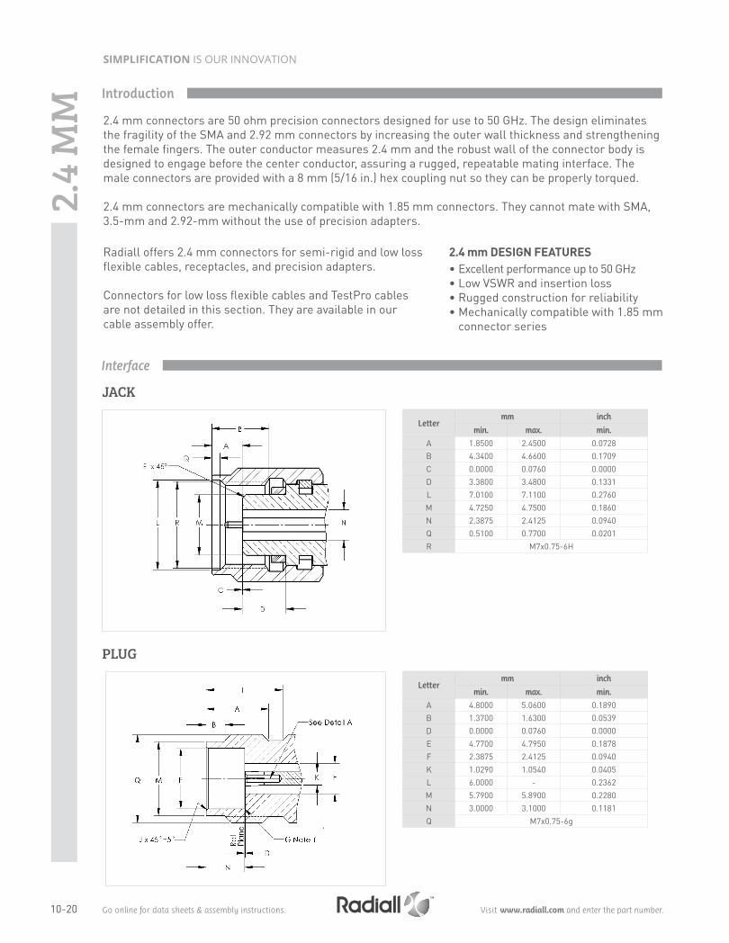
Radiall offers 2.4 mm connectors for semi-rigid and low loss flexible cables, receptacles, and precision adapters. Connectors for low loss flexible cables and TestPro cables are not detailed in this section. They are available in our cable assembly offer.
2.4
MM
JACK
Interface
Lettermm inch
min. max. min.
A 1.8500 2.4500 0.0728B 4.3400 4.6600 0.1709C 0.0000 0.0760 0.0000D 3.3800 3.4800 0.1331L 7.0100 7.1100 0.2760M 4.7250 4.7500 0.1860N 2.3875 2.4125 0.0940Q 0.5100 0.7700 0.0201R M7x0.75-6H
PLUG
Lettermm inch
min. max. min.
A 4.8000 5.0600 0.1890B 1.3700 1.6300 0.0539D 0.0000 0.0760 0.0000E 4.7700 4.7950 0.1878F 2.3875 2.4125 0.0940K 1.0290 1.0540 0.0405L 6.0000 - 0.2362M 5.7900 5.8900 0.2280N 3.0000 3.1000 0.1181Q M7x0.75-6g
Introduction
2.4 mm connectors are 50 ohm precision connectors designed for use to 50 GHz. The design eliminates the fragility of the SMA and 2.92 mm connectors by increasing the outer wall thickness and strengthening the female fingers. The outer conductor measures 2.4 mm and the robust wall of the connector body is designed to engage before the center conductor, assuring a rugged, repeatable mating interface. The male connectors are provided with a 8 mm (5/16 in.) hex coupling nut so they can be properly torqued. 2.4 mm connectors are mechanically compatible with 1.85 mm connectors. They cannot mate with SMA, 3.5-mm and 2.92-mm without the use of precision adapters.

10-21Go online for data sheets & assembly instructions. Visit www.radiall.com and enter the part number.
SIMPLIFICATION IS OUR INNOVATION
ELECTRICAL CHARACTERISTICS Impedance 50ΩFrequency range DC - 50 GHzV.S.W.R. < 1.05 + 0.003 F (GHz)Insertion loss 0.04 √ F (GHz)RF leakage – 100 dB maxInsulation resistance <= 1400Veff - contact resistance > 5000 mΩ
Contact resistance • Outer conductor • inner conductor
< 0.8 mΩ < 4 mΩ
Voltage rating 250 V(RMS)Dielectric withstanding voltage 500 V(RMS)
MECHANICAL CHARACTERISTICSMechanical endurance 500 matingsForce to engage and disengage < 23 N cmMating torque 90 N cmCoupling nut retention force < 272 N
Cable retention force• Outer conductor• inner conductor
130 N
Contact captivation 27N
ENVIRONMENTAL CHARACTERISTICSTemperature range -65°C / + 165°CThermal shock MIL STD 202, method 107, condition B, -65°C / + 165°CHigh temperature test MIL STD 202, method 108, condition D, 1000 H at 150°CCorrosion (salt spray) MIL STD 202, method 101, condition B, 48 H / 35°C / 5 %Vibration MIL STD 202, method 204, condition H, 30g RMSShock MIL STD 202, method 213, condition I, 100gMoisture resistance MIL STD 202, method 106, 80% / 100% 25°C / 65°C 10 cycles
MATERIALS AND PLATING Material Plating
Bodies Beryllium copper Cu2.5 Au0.8Outer contact (body insert) Brass Cu2.5 Au0.8Center contacts Beryllium copper Ni2 Au1.3Coupling nut Stainless steel PassivatedGaskets Silicone rubber -Insulators PEEK -
Test / Characteristics Values / Remarks
Characteristics
2.4
MM

10-22 Go online for data sheets & assembly instructions. Visit www.radiall.com and enter the part number.
SIMPLIFICATION IS OUR INNOVATION
STRAIGHT PLUGS, SOLDER TYPE FOR SEMI-RIGID CABLES
Plugs, Jacks and Receptacles
STRAIGHT JACKS, SOLDER TYPE FOR SEMI-RIGID CABLES
Cable group Cable group dia. Fig. Part number Captive center contact
RG405
.085"1
R327 222 000
Yes.085" microporous R327 222 200
.085"2
R327 316 000.085" microporous R327 316 010
Fig. 1Fig. 2
UNIVERSAL SCREW-ON FEMALE RECEPTACLES
Part number Using with glass bead For pin diameter
R327 556 000 R280 760 040 0.3 (0.12)
2.4
MM
Cable group Cable group dia. Part number Captive center contact
RG405 .085" R327 052 000Yes
RG405 .085" microporous R327 052 202

10-23Go online for data sheets & assembly instructions. Visit www.radiall.com and enter the part number.
SIMPLIFICATION IS OUR INNOVATION
Fig. 1 Fig. 2
Fig. 3
Part number Fig. Captive center contact Panel drilling Use with
glass beadFor pin
diameter
R327 430 000 1Yes
P01R280 760 040 0.3 (0.12)R327 411 000 2
R327 465 000 3 P02
Receptacles and Glass Bead
FLANGE RECEPTACLES
GLASS BEAD
Part number Packaging
R280 760 040 100
2.4
MM

10-24 Go online for data sheets & assembly instructions. Visit www.radiall.com and enter the part number.
SIMPLIFICATION IS OUR INNOVATION
IN SERIES ADAPTERS
Part number Fig. Note
R327 703 000 1 Male / MaleR327 704 000 2 Male / FemaleR327 705 000 3 Female / FemaleR327 771 000 4 Male / Female right angle
Fig. 1 Fig. 2
Fig. 3 Fig. 4
In Series Adapters and Panel Drilling
Panel Drilling
P01 P02
Lettermm inch
min. max. min. max.
A 1.63 1.60 0.064 0.063B 2.70 2.60 0.106 0.102C 8.69 8.59 0.342 0.338
2.4
MM