high efficiency. multi-functional machining of aluminium
TRANSCRIPT

TOOL NEWS
AlimasterNew
B264G
Series Expansion
2021.9 Update
High Efficiency. Multi-functional Machining of Aluminium AlloysNew DLC coated type added to the range for even better welding resistance.
High Efficiency Machining of Aluminium Alloys

1
AlimasterNew
A3SA
A3SARB
APMXCurved Edge
Helical internal through coolant holes, together with an optimised cutting edge geometry enables highly efficient machining.
High Efficiency Machining of Aluminium Alloys
Iregular Helix and Curved Flute Exit Geometry Radius Flute Exit Geometry
Helical Through Coolant Holes
Strengthened Centre Cutting Edges
Ideal Flute Geometry
Suppresses chatter to enable excellent surface finishes.
Chip discharge during plunging, ramping and grooving have been significantly improved, for stable, high efficiency cutting.Helical holes maintain a stable coolant supply even after re-grinding.
Optimised centre cutting edges provide strength and reliability even during plunging.
The cross sectional geometry of the flutes is perfect for efficient chip discharge and prevents chip jamming commonly associated with high feed machining of aluminium.
Square End Mill, 3 Flute
Radius End Mill, 3 Flute

2
0 3 6 9 12
A1050
A5052
A6063
A7075
DLC3SA
DLC3SARB
ap = 12 mm ap = 3 mm
Square End Mill, 3 Flute
Radius End Mill, 3 Flute
Alu
min
ium
Allo
ys
Depth of Cut ap (mm)
DLC Coating
DLC Coating
Uncoated
Uncoated
<Cutting Conditions>Tool : DC = ø12 mmCutting Speed : vc = 452m/minFeed per Tooth : fz = 0.1mm/t.Overhang Length : 36mmCutting Mode : Dry Cutting
By adopting a unique DLC coating with excellent adhesion and welding resistance, cutting friction is reduced thereby provides extra stability and efficiency. Additionally wet or dry cutting is possible for slot milling and contouring.
DLC CoatingHigh Efficiency & Economy
Dry Slot Milling - Comparison when Machining Different MaterialsThe excellent welding resistance and chip evacuation properties enables high efficiency slot milling even at large depths of cut.
DLC coatings may differ naturally in colour. This has no effect on quality or performance.
* Air blow both internal and external is used to effectively evacuate chips.
Chip Adhesion
Chip Adhesion
Chip Adhesion
3
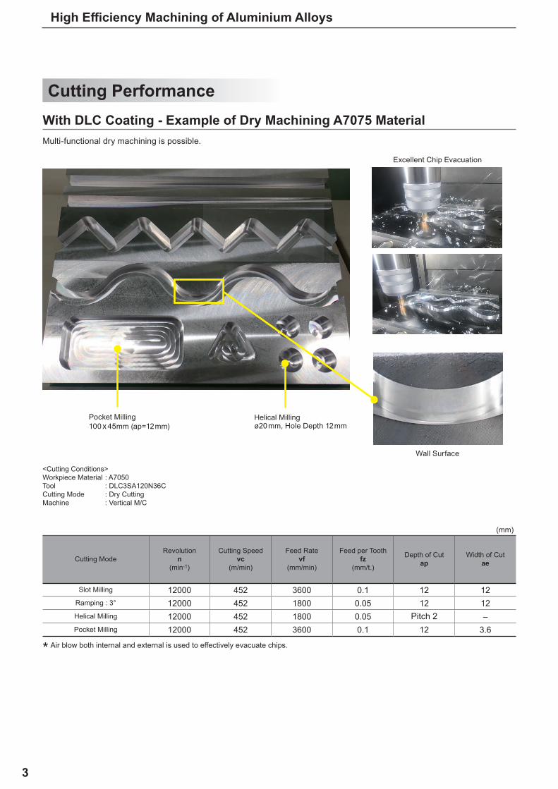
12000 452 3600 0.1 12 1212000 452 1800 0.05 12 1212000 452 1800 0.05 –12000 452 3600 0.1 12 3.6
(mm)
High Efficiency Machining of Aluminium Alloys
Cutting Performance
<Cutting Conditions>Workpiece Material : A7050Tool : DLC3SA120N36CCutting Mode : Dry CuttingMachine : Vertical M/C
Cutting ModeRevolution
n(min-1)
Cutting Speedvc
(m/min)
Feed Ratevf
(mm/min)
Feed per Toothfz
(mm/t.)
Depth of Cutap
Width of Cutae
Slot Milling
Ramping : 3°
Helical Milling Pitch 2Pocket Milling
Pocket Milling100x45mm (ap=12mm)
Helical Millingø20mm, Hole Depth 12mm
Wall Surface
With DLC Coating - Example of Dry Machining A7075 MaterialMulti-functional dry machining is possible.
* Air blow both internal and external is used to effectively evacuate chips.
Excellent Chip Evacuation

4
New
12000 452 3600 0.1 12 1212000 452 1800 0.05 12 1212000 452 1800 0.05 –12000 452 3600 0.1 12 3.6
25500.32
30200.38
35000.44
Alimaster
<Cutting Conditions>Workpiece Material : A7050Tool : A3SA120N36C DC = ø12 mmCutting Speed : vc = 100m/minDepth of Cut : ap = 12mmOverhang Length : 36mmCutting Mode : Internal Coolant (Water-soluble Coolants)
Feed Rate (mm/min)
Feed per Tooth (mm/t.)
Conventional A
Conventional B
Breakage due to chip clogging
Breakage due to chip clogging
Uncoated Type - Slot Machining A7050 MaterialUtilising internal coolant and an optimised cutting edge geometry enables double the efficiency levels of conventional products.
Good Wall Surface
Good Wall Surface
Good Wall Surface Good Wall Surface
Cutting ModeRevolution
n(min-1)
Cutting Speedvc
(m/min)
Feed Ratevf
(mm/min)
Feed per Toothfz
(mm/t.)
Depth of Cutap
Width of Cutae
Slot Milling
Ramping : 3°
Helical Milling Pitch 2Pocket Milling

5
New
New
10400.13
12800.16
15200.19
Alimaster
Alimaster
High Efficiency Machining of Aluminium Alloys
Cutting Performance
<Cutting Conditions>Workpiece Material : A7050Tool : A3SA120N36C DC = ø12 mmCutting Speed : vc = 300m/minDepth of Cut : ap = 12mmOverhang Length : 36mmCutting Mode : Internal Coolant (Water-soluble Coolants)
Feed Rate (mm/min)
Feed per Rev. (mm/rev)
Conventional Fracture
After F=1520 mm/min, fz=0.19 mm/rev Plunging
Uncoated Type - Plunge Machining A7050 MaterialHigher feed rates than conventional products brings greater machining efficiencies.
Strengthened Centre Cutting Edges

6
DC =APMX =LU =DN =
LF =DCON =
e
DLC3SA
DC APMX LU DN LF DCON
DLC3SA120N36C 12 18 36 11.4 80 12 3 a
DLC3SA160N48C 16 24 48 15.4 90 16 3 a
DLC3SA200N55C 20 30 55 18 100 20 3 a
DLC3SA250N55C 25 37.5 55 23 100 25 3 a
DC=12 DC>12 0- 0.020
0- 0.030
0- 0.011
0- 0.013
APMXLU
DC
DC
ON
LF
DN
APMX
37.5°
Carbon Steel, Alloy Steel, Cast Iron (<30HRC)
Tool Steel, Pre-hardened Steel,Hardened Steel (<45HRC)
Hardened Steel (<55HRC)
Hardened Steel (>55HRC)
Austenitic Stainless Steel
Titanium AlloyHeat Resistant Alloy Copper Alloy Aluminium Alloy
a : Inventory maintained in Japan.
Cutting Dia.Depth of Cut Max.Usable LengthNeck Dia.
Functional LengthConnection Dia.
* Number of Flutes
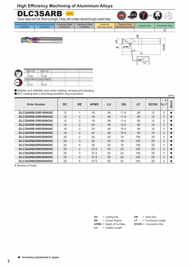
End mill, Short cut length, 3 flute, with multiple internal through coolant holes
Order Number No.F
Stoc
k
12<DCON<16 20<DCON<25
*
CurvedEdge
a
a
Stability and reliability even when slotting, ramping and plunging.DLC coating aids in providing excellent chip evacuation.
7
e
DLC3SARB
DC RE APMX LU DN LF DCON
DLC3SARB120R100N36C 12 1 18 36 11.4 80 12 3 a
DLC3SARB120R200N36C 12 2 18 36 11.4 80 12 3 a
DLC3SARB120R300N36C 12 3 18 36 11.4 80 12 3 a
DLC3SARB160R200N48C 16 2 24 48 15.4 90 16 3 a
DLC3SARB160R300N48C 16 3 24 48 15.4 90 16 3 a
DLC3SARB160R400N48C 16 4 24 48 15.4 90 16 3 a
DLC3SARB200R200N55C 20 2 30 55 18 100 20 3 a
DLC3SARB200R300N55C 20 3 30 55 18 100 20 3 a
DLC3SARB200R400N55C 20 4 30 55 18 100 20 3 a
DLC3SARB250R200N55C 25 2 37.5 55 23 100 25 3 a
DLC3SARB250R300N55C 25 3 37.5 55 23 100 25 3 a
DLC3SARB250R400N55C 25 4 37.5 55 23 100 25 3 a
DLC3SARB250R500N55C 25 5 37.5 55 23 100 25 3 a
(mm)
DC=12 DC>12 0- 0.020
0- 0.030
0- 0.011
0- 0.013
DC =RE =APMX =LU =
DN =LF =DCON =
37.5°
APMX
DC
DC
ON
LF
RE
DN
LU
APMX
High Efficiency Machining of Aluminium Alloys
Carbon Steel, Alloy Steel, Cast Iron (<30HRC)
Tool Steel, Pre-hardened Steel,Hardened Steel (<45HRC)
Hardened Steel (<55HRC)
Hardened Steel (>55HRC)
Austenitic Stainless Steel
Titanium AlloyHeat Resistant Alloy Copper Alloy Aluminium Alloy
a : Inventory maintained in Japan.
Order Number No.F
Stoc
k*
* Number of Flutes
Corner radius end mill, Short cut length, 3 flute, with multiple internal through coolant holes
CurvedEdge
a
a
Stability and reliability even when slotting, ramping and plunging.DLC coating aids in providing excellent chip evacuation.
12<DCON<16 20<DCON<25
Cutting Dia.Corner RadiusDepth of Cut Max.Usable Length
Neck Dia.Functional LengthConnection Dia.

8
DC =APMX =LU =DN =
LF =DCON =
e
A3SA
DC APMX LU DN LF DCON
A3SA120N36C 12 18 36 11.4 80 12 3 a
A3SA160N48C 16 24 48 15.4 90 16 3 a
A3SA200N55C 20 30 55 18 100 20 3 a
A3SA250N55C 25 37.5 55 23 100 25 3 a
DC=12 DC>12 0- 0.020
0- 0.030
0- 0.011
0- 0.013
APMXLU
DC
DC
ON
LF
DN
APMX
37.5°
Carbon Steel, Alloy Steel, Cast Iron (<30HRC)
Tool Steel, Pre-hardened Steel,Hardened Steel (<45HRC)
Hardened Steel (<55HRC)
Hardened Steel (>55HRC)
Austenitic Stainless Steel
Titanium AlloyHeat Resistant Alloy Copper Alloy Aluminium Alloy
Cutting Dia.Depth of Cut Max.Usable LengthNeck Dia.
Functional LengthConnection Dia.
* Number of Flutes
End mill, Short cut length, 3 flute, with multiple internal through coolant holes
Order Number No.F
Stoc
k
12<DCON<16 20<DCON<25
*
CurvedEdge
a
a
Stability and reliability even when slotting, ramping and plunging.The cross sectional geometry of the flutes is perfect for efficient chip discharge.

9
e
A3SARB
DC RE APMX LU DN LF DCON
A3SARB120R100N36C 12 1 18 36 11.4 80 12 3 a
A3SARB120R200N36C 12 2 18 36 11.4 80 12 3 a
A3SARB120R300N36C 12 3 18 36 11.4 80 12 3 a
A3SARB160R200N48C 16 2 24 48 15.4 90 16 3 a
A3SARB160R300N48C 16 3 24 48 15.4 90 16 3 a
A3SARB160R400N48C 16 4 24 48 15.4 90 16 3 a
A3SARB200R200N55C 20 2 30 55 18 100 20 3 a
A3SARB200R300N55C 20 3 30 55 18 100 20 3 a
A3SARB200R400N55C 20 4 30 55 18 100 20 3 a
A3SARB250R200N55C 25 2 37.5 55 23 100 25 3 a
A3SARB250R300N55C 25 3 37.5 55 23 100 25 3 a
A3SARB250R400N55C 25 4 37.5 55 23 100 25 3 a
A3SARB250R500N55C 25 5 37.5 55 23 100 25 3 a
(mm)
DC=12 DC>12 0- 0.020
0- 0.030
0- 0.011
0- 0.013
DC =RE =APMX =LU =
DN =LF =DCON =
37.5°
APMX
DC
DC
ON
LF
RE
DN
LU
APMX
High Efficiency Machining of Aluminium Alloys
Carbon Steel, Alloy Steel, Cast Iron (<30HRC)
Tool Steel, Pre-hardened Steel,Hardened Steel (<45HRC)
Hardened Steel (<55HRC)
Hardened Steel (>55HRC)
Austenitic Stainless Steel
Titanium AlloyHeat Resistant Alloy Copper Alloy Aluminium Alloy
a : Inventory maintained in Japan.
Order Number No.F
Stoc
k*
* Number of Flutes
a : Inventory maintained in Japan.
Corner radius end mill, Short cut length, 3 flute, with multiple internal through coolant holes
CurvedEdge
a
a
Stability and reliability even when slotting, ramping and plunging.The cross sectional geometry of the flutes is perfect for efficient chip discharge.
12<DCON<16 20<DCON<25
Cutting Dia.Corner RadiusDepth of Cut Max.Usable Length
Neck Dia.Functional LengthConnection Dia.

10
12 1240 33000 15000 6 1216 1660 33000 20000 8 1620 2070 33000 26000 10 2025 2590 33000 32000 12.5 25
12 600 16000 7200 6 1216 600 12000 7200 8 1620 600 9500 7400 10 2025 600 7600 7300 12.5 25
12 1240 33000 15000 616 1660 33000 20000 820 2070 33000 26000 1025 2590 33000 32000 12.5
12 600 16000 7200 616 600 12000 7200 820 600 9500 7400 1025 600 7600 7300 12.5
y
y
y
y
(mm)
(mm)
(mm)
(mm)
A3SA/A3SARB, DLC3SA/DLC3SARB
DC
DC
ap
ap
ae
ae
ap
ap
Note 1) It is recommended to use a water-soluble coolant. It is also possible to use air blow (external/internal) for DLC coated types.Note 2) Climb milling is recommended for side cutting.Note 3) This table shows the cutting condition with less than 4D overhang length. If more than 4D, spindle speed, feed rate and depth of cut
should be reduced.Note 4) When ramping, consider the chip discharge and use a feed rate 50% lower than the slotting conditions above and also use a ramping
angle of 5º or less. Note 5) If the rigidity of the machine or the workpiece materials installation is very low, or chattering and noise are generated, reduce the
revolution and feed rate proportionately within the range described in the above table, or reduce the depth and width of cut.
DC:Cutting Dia.
DC:Cutting Dia.
Side Milling
Side Milling
Slot Milling
Slot Milling
WorkpieceMaterial Aluminium Alloys
WorkpieceMaterial Aluminium Alloys
WorkpieceMaterial Aluminium Alloys
WorkpieceMaterial Aluminium Alloys
Recommended Cutting ConditionsUse high efficiency cutting conditions when the machine and workpiece rigidity, and chip evacuation properties are sufficient.Use lower, general-purpose cutting conditions when the mechanical or workpiece rigidity or chip evacuation porperties are insufficient.
High Efficiency Conditions
General-purpose Conditions
Dia.DC
Cutting Speed(m/min)
Revolution(min-1)
Feed Rate(mm/min)
Depth of Cutae(mm)
Depth of cutap(mm)
Depth ofCut
Dia.DC
Cutting Speed(m/min)
Revolution(min-1)
Feed Rate(mm/min)
Depth of Cutae(mm)
Depth of cutap(mm)
Depth ofCut
Dia.DC
Cutting Speed(m/min)
Revolution(min-1)
Feed Rate(mm/min)
Depth of Cutap(mm)
Depth ofCut
Dia.DC
Cutting Speed(m/min)
Revolution(min-1)
Feed Rate(mm/min)
Depth of Cutap(mm)
Depth ofCut

MITSUBISHI MATERIALS CORPORATION
Overseas Sales Dept, Asian RegionKFC bldg., 8F, 1-6-1 Yokoami, Sumida-ku, Tokyo 130-0015, JapanTEL +81-3-5819-8771 FAX +81-3-5819-8774
Overseas Sales Dept, European & American RegionKFC bldg., 8F, 1-6-1 Yokoami, Sumida-ku, Tokyo 130-0015, JapanTEL +81-3-5819-8772 FAX +81-3-5819-8774
2020.9.( - )EXP-20-E007
http://www.mitsubishicarbide.com/en/(Tools specifications subject to change without notice.)
For Your SafetyaDon't handle inserts and chips without gloves. aPlease machine within the recommended application range and exchange expired tools with new ones in advance of breakage. aPlease use safety covers and wear safety glasses. aWhen using compounded cutting oils, please take fire precautions. aWhen attaching inserts or spare parts, please use only the correct wrench or driver. aWhen using rotating tools, please make a trial run to check run-out, vibration and abnormal sounds etc.
Cutting Example
<Cutting Conditions>Workpiece Material : A7050Tool : A3SARB250R300N55C DC = ø25 mm, RE=3.0mmSpindle Revolution : 33000min-1 Cutting Speed : vc = 2600m/minFeed Rate : f = 25000mm/min Feed : fz = 0.25mm/t. Depth of Cut : ap = 16mm, ae=25mmCutting Mode : Internal Coolant (Water-soluble Coolants)Machine : For machining aluminium
structural parts for aircraft High-speed, high-output horizontal 5-axis M/C
Machining with a High-speed, High-output Horizontal 5-axis Machining CentreUltra-high efficiency processing was achieved with a stable chip discharge and no chattering.Metal Removal Rate of 10,000 cm3/min.