high efficiency microgroove coils for commercial & industrial applications ahr show
DESCRIPTION
High Efficiency MicroGroove Coils For Commercial & Industrial Applications AHR Show January 29, 2013. MicroGroove Coils. Super Radiator Coils Wind Tunnel Test Lab Why MicroGroove Works Benefits of MicroGroove Application. Super Radiator Coils. Heat Transfer Specialists Since 1928. - PowerPoint PPT PresentationTRANSCRIPT
High Efficiency MicroGroove CoilsFor
Commercial & Industrial Applications
AHR ShowJanuary 29, 2013
MicroGroove Coils
Super Radiator Coils
Wind Tunnel Test Lab
Why MicroGroove Works
Benefits of MicroGroove
Application
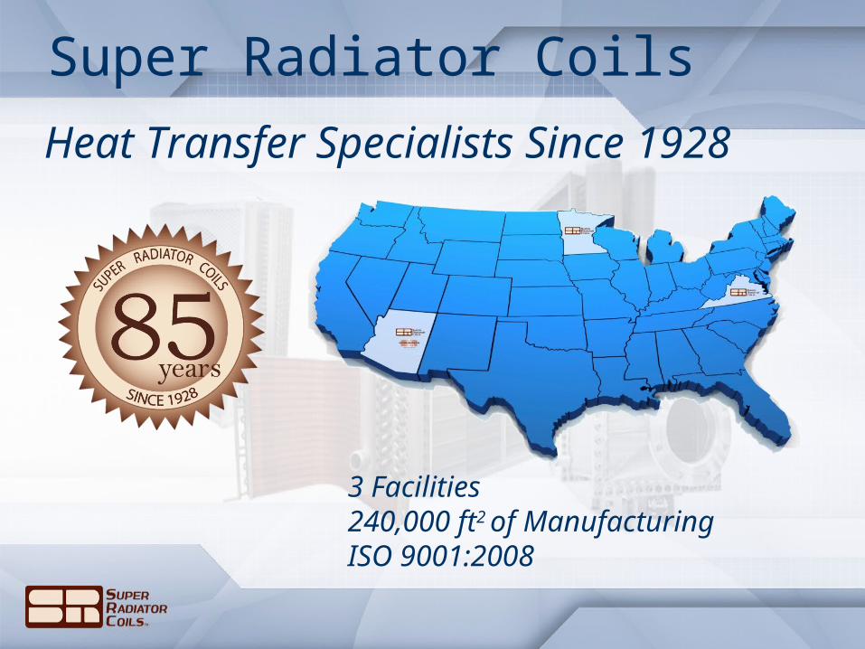
Super Radiator Coils
Heat Transfer Specialists Since 1928
3 Facilities240,000 ft2 of ManufacturingISO 9001:2008
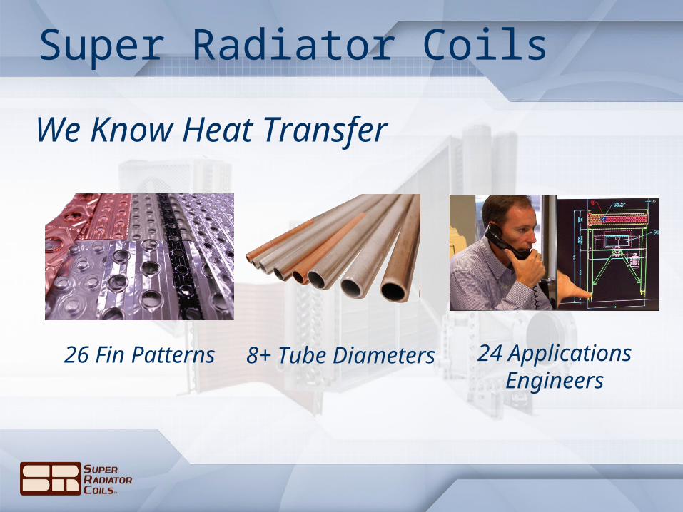
Super Radiator Coils
We Know Heat Transfer
26 Fin Patterns 8+ Tube Diameters 24 ApplicationsEngineers

Super Radiator Coils
A Full Range Of Commercial & Industrial Coils
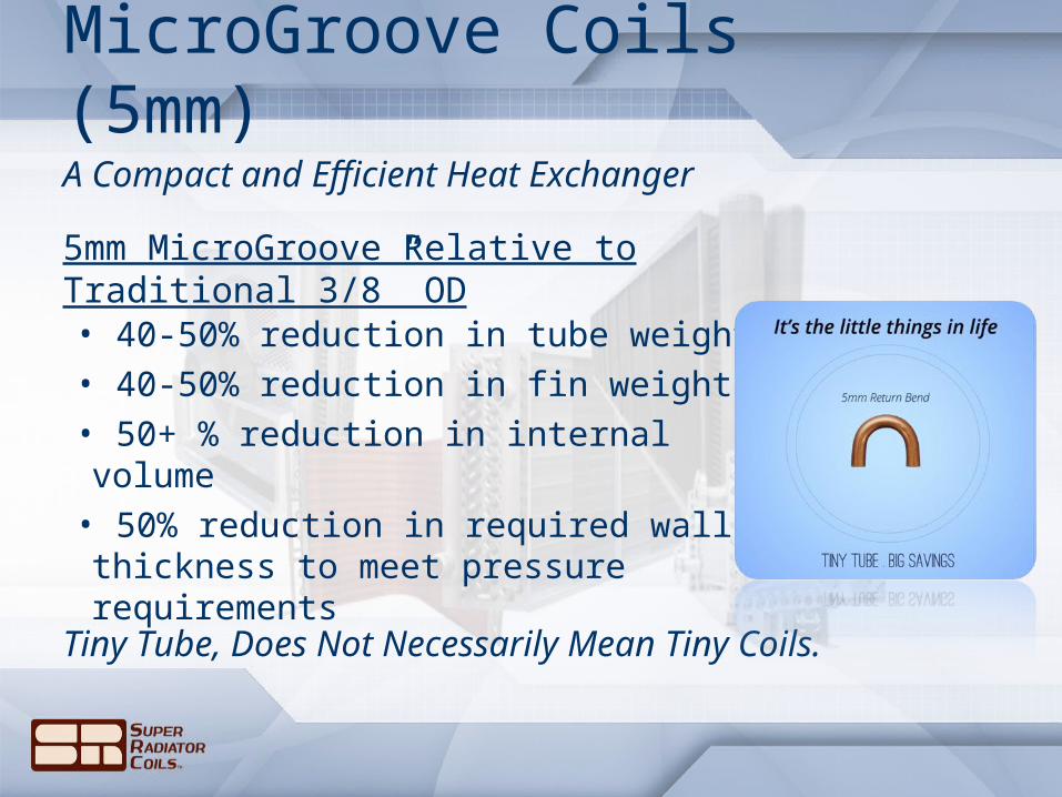
MicroGroove Coils (5mm)
A Compact and Efficient Heat Exchanger
• 40-50% reduction in tube weight• 40-50% reduction in fin weight• 50+ % reduction in internal volume• 50% reduction in required wall thickness to meet pressure requirements
Tiny Tube, Does Not Necessarily Mean Tiny Coils.
5mm MicroGroove Relative to Traditional 3/8” OD

Wind Tunnel & Test LabThe MicroGroove coils were developed in Super Radiator Coils wind tunnel test lab in Richmond, VA
Learn more about the test lab at: http://www.srcoils.com/news-events/2012/11/test-lab/
• Airflow from 100 – 8,000 cubic feet per minute.• Air temperatures from 35°F – 140°F and humidity from 40 – 95%.
• Separate fluid testing loops for: Refrigerants, Water, Glycol, Oil, & Steam
• Available for 3rd Party Testing Services
Dr. Jian YuDirector of Product Development

Q = U A x ∆T
What Drives The Efficiency?
Less Metal Required For the Same Effective Area (A)
Better Inside Heat Transfer Coefficient (hi ) andBetter Outside Heat Transfer Coefficient (ho)
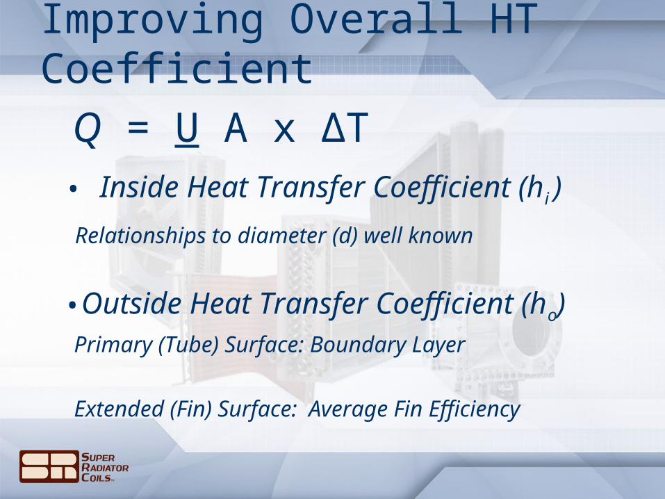
Q = U A x ∆T
Improving Overall HT Coefficient
• Inside Heat Transfer Coefficient (hi )
Relationships to diameter (d) well known
•Outside Heat Transfer Coefficient (ho)Primary (Tube) Surface: Boundary Layer
Extended (Fin) Surface: Average Fin Efficiency

Improving ho On Primary SurfaceQ = U A x ∆T
Reducing the Effect of the Boundary Layer
Boundary Layer
Proportional Reduction
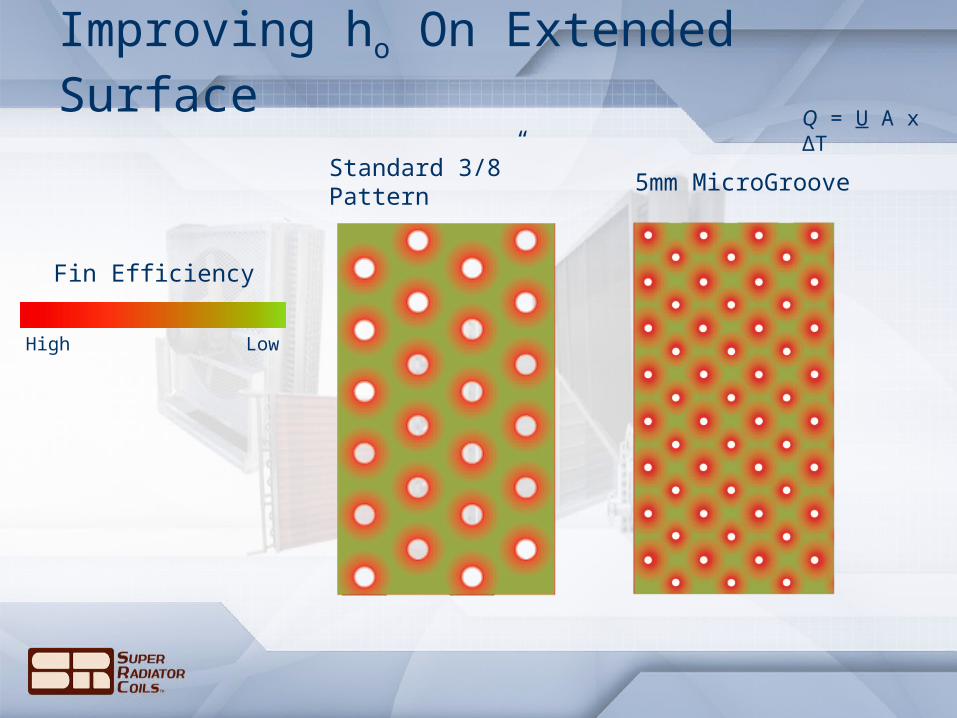
Standard 3/8” Pattern 5mm MicroGroove
Improving ho On Extended SurfaceQ = U A x ∆T
Fin Efficiency
High Low
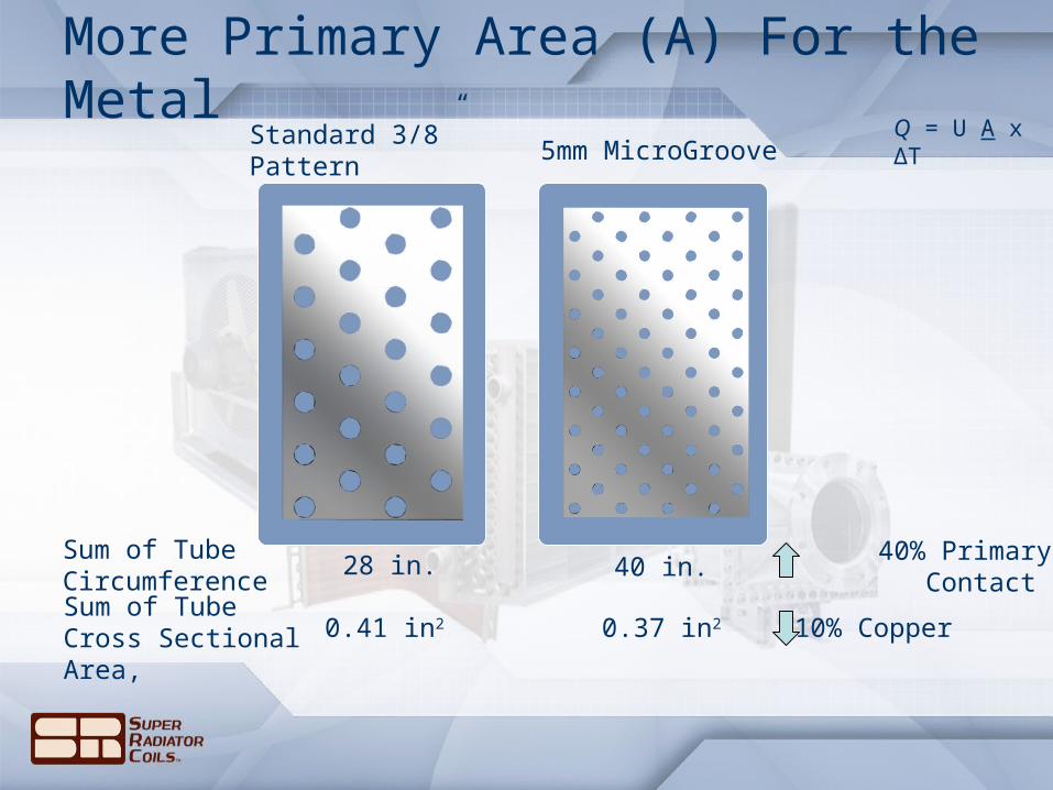
More Primary Area (A) For the MetalQ = U A x ∆T
Standard 3/8” Pattern
Sum of Tube Cross Sectional Area,
0.41 in2 0.37 in2 10% Copper
Sum of TubeCircumference
28 in. 40 in. 40% Primary Contact
5mm MicroGroove

Q = U A x ∆T
Compounding Benefit
Less Metal Required For the Same Effective Area (A)
Better Inside Heat Transfer Coefficient (hi ) andBetter Outside Heat Transfer Coefficient (ho)
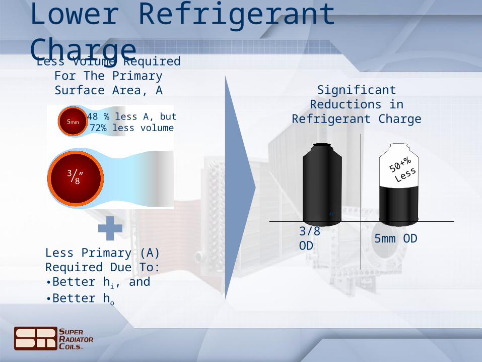
Lower Refrigerant ChargeLess Volume Required For
The Primary Surface Area, A
48 % less A, but72% less volume
Less Primary (A) Required Due To:•Better hi, and•Better ho
50+
%
Less
Significant Reductions in Refrigerant Charge
3/8” OD 5mm OD
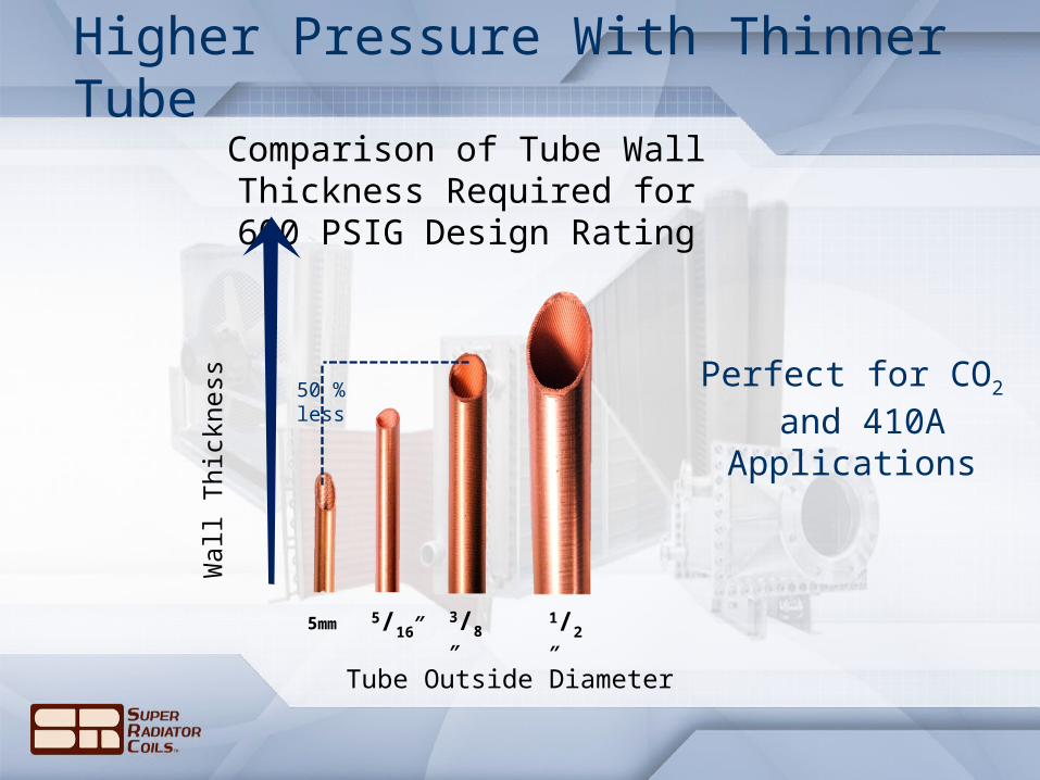
Comparison of Tube Wall Thickness Required for 600
PSIG Design Rating
3/8″
1/2″
5/16″5mm
Wall
Thic
kness
Higher Pressure With Thinner Tube
Tube Outside Diameter
Perfect for CO2 and 410A
Applications
50 % less

Evaporator Coils
Large Multi-Row Condensers
Flexible Sizes and Configurations
Formable Coils & Copper Fins
Other Compact Designs
More Than Refrigerant Coils
Oil Coolers
Compressed Air Coolers
Closed Loop Water Coils

What Problem Are You Solving?
SEER Rating Improvements

MicroGroove Coils Available Today
Preliminary Selections
Controlled Testing
Rapid Prototypes
Volume Production

Contact
Super Radiator Coils
Booth #1737
www.superradiatorcoils.com/microgroove
We Know Heat Transfer
Matt Holland
Vice President of Operations
Super Radiator Coils
804-794-2887