high dno/dt liquid crystals and their applications in a thermally
TRANSCRIPT

High dno/dT Liquid Crystals and their Applications in aThermally Tunable Liquid Crystal Photonic Crystal Fiber
Jun LiSebastian GauzaShin-Tson WuCollege of Optics and Photonics, University of Central Florida,Orlando, Florida, USA
Thomas Tanggaard AlkeskjoldJesper LægsgaardAnders BjarklevCOM Center, Technical University of Denmark, Lyngby, Denmark
We have analyzed the physical origins of the temperature gradient of the ordinaryrefractive index (dno=dT) of liquid crystals. To achieve a large dno=dT, highbirefringence (Dn) and low clearing temperature play crucial roles. Based on theseguidelines, we formulated two exemplary liquid crystal mixtures, designated asUCF-1 and UCF-2. The dno=dT of UCF-1 is �4� higher than that of 5CB atroom temperature. By infiltrating UCF-1 into the air holes of a three-rod corephotonic crystal fiber, we demonstrate a thermally tunable photonic bandgap fiberwith tuning sensitivity of 27 nm=�C at room temperature. The insertion loss is lessthan 0.5 dB.
Keywords: high dno=dT; liquid crystals; microstructure devices; photonic crystal fiber
I. INTRODUCTION
Liquid crystals (LCs) have been widely used in display industry,e.g., laptop computers, desktop monitors, projection displays, high-definition TVs, personal digital assistants (PDAs), liquid-crystal-on-silicon (LCoS) for rear projection TVs, etc. [1–4]. Besides displays,LCs are also useful for photonic devices such as optical phasedarray for laser beam steering [5], light switches [6], variable optical
Address correspondence to Jun Li, College of Optics and Photonics, University ofCentral Florida, Orlando, 32816 Florida, USA. E-mail: [email protected]
Mol. Cryst. Liq. Cryst., Vol. 453, pp. 355–370, 2006
Copyright # Taylor & Francis Group, LLC
ISSN: 1542-1406 print=1563-5287 online
DOI: 10.1080/15421400600653894
355

attenuator [7], thermal solitons in nematic LCs [8,9], and thermallytunable LC photonic crystal fibers [10–12]. For laser beam steering,high birefringence (Dn) and low viscosity LCs are preferred in orderto obtain fast response time. On the other hand, LC materials witha high temperature gradient in refractive indices, especially theordinary refractive index, are highly desirable for triggering the ther-mal solutions in nematic liquid crystals and for improving the thermaltuning sensitivity of the bandgaps of a liquid crystal photonic crystalfiber (LCPCF).
Comparing with isotropic liquids, LCs have inherent large tempera-ture gradients for both ne (extraordinary ray) and no (ordinary ray).For some commercial LC compounds such as 5CB and 6CB, theirtemperature gradient of the refractive indices is �10�4 at room tem-perature (RT). A small dno=dT means that a higher laser power isneeded in order to observe the thermal effect. To enhance thedno=dT value, new LC mixtures need to be developed [13].
In this paper, we analyze the factors affecting the dno=dT of a LCmaterial based on the four-parameter model, which describes thetemperature-dependent refractive indices. Guidelines are developedfor tailoring new LC materials with high dno=dT at RT. Two newLC mixtures, designated as UCF-1 and UCF-2 are formulated in ourlab. A highly tunable large-core single-mode photonic bandgap fiberwas infiltrated with UCF-1 into the micro holes around the silica coreof a three-rod core photonic crystal fiber. A bandgap tuning sensitivityof 27 nm=�C is achieved at RT. The insertion loss is estimated to be lessthan 0.5 dB and mainly caused by coupling loss between the index-guided mode and the bandgap-guided mode. In Sec. II, we derivedthe physical models for dno=dT, temperature gradient of ordinaryrefractive index, and dne=dT, temperature gradient of extraordinaryrefractive index based on the four-parameter model. The factors affect-ing dno=dT are disclosed. In Sec. III, we describe the compositions ofUCF-1 and UCF-2 which have a large dno=dT at RT. The electro-opticproperties of these two mixtures are presented. We also compare thedno=dT value of these two new mixtures with 5CB and 6CB. In Sec.IV, we evaluate the highly tunable LC photonic crystal fiber by infil-trating UCF-1 into a section of three-rod core photonic crystal fiberwith 10 mm length.
II. THEORY
Based on the Vuks model [14] and Haller equation [15], we derived thefour-parameter model for describing the temperature effect on LCrefractive indices. Equations (1a) and (1b) show the expressions for
356 J. Li et al.
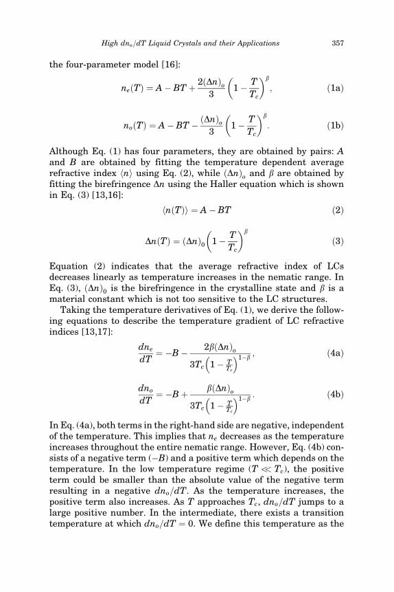
the four-parameter model [16]:
neðTÞ ¼ A� BT þ 2ðDnÞo3
1� T
Tc
� �b
; ð1aÞ
noðTÞ ¼ A� BT � ðDnÞo3
1� T
Tc
� �b
: ð1bÞ
Although Eq. (1) has four parameters, they are obtained by pairs: Aand B are obtained by fitting the temperature dependent averagerefractive index hni using Eq. (2), while ðDnÞo and b are obtained byfitting the birefringence Dn using the Haller equation which is shownin Eq. (3) [13,16]:
hnðTÞi ¼ A� BT ð2Þ
DnðTÞ ¼ ðDnÞ0 1� T
Tc
� �b
ð3Þ
Equation (2) indicates that the average refractive index of LCsdecreases linearly as temperature increases in the nematic range. InEq. (3), ðDnÞ0 is the birefringence in the crystalline state and b is amaterial constant which is not too sensitive to the LC structures.
Taking the temperature derivatives of Eq. (1), we derive the follow-ing equations to describe the temperature gradient of LC refractiveindices [13,17]:
dne
dT¼ �B� 2bðDnÞo
3Tc 1� TTc
� �1�b; ð4aÞ
dno
dT¼ �Bþ bðDnÞo
3Tc 1� TTc
� �1�b: ð4bÞ
In Eq. (4a), both terms in the right-hand side are negative, independentof the temperature. This implies that ne decreases as the temperatureincreases throughout the entire nematic range. However, Eq. (4b) con-sists of a negative term (�B) and a positive term which depends on thetemperature. In the low temperature regime (T << Tc), the positiveterm could be smaller than the absolute value of the negative termresulting in a negative dno=dT. As the temperature increases, thepositive term also increases. As T approaches Tc, dno=dT jumps to alarge positive number. In the intermediate, there exists a transitiontemperature at which dno=dT ¼ 0. We define this temperature as the
High dno=dT Liquid Crystals and their Applications 357

crossover temperature To for no. To find To, we simply solvedno=dT ¼ 0 from Eq. (4b). In the T< To regime, no decreases as tem-perature increases, but when T >To, no increases as temperatureincreases. Beyond the clearing point Tc, no equals to ne and the opticalanisotropy disappears [13].
From Eq. (4b), dno=dT is determined by five parameters (B, b,ðDnÞ0, T and Tc). Among these five, b and T can be treated as con-stants: b � 0:2 and T � 295 K since the preferred operation tempera-ture is around RT. Therefore, we only need to consider theremaining three parameters: B, ðDnÞ0, and Tc. A smaller B helps toboost the dno=dT value. Among the LC materials investigated, wefound that the compounds containing isothiocyannato (NCS) polargroup possess a slightly smaller B coefficient and higher birefringencethan the cyano (CN) compounds. Some experimental evidences will beshown later. Therefore, the remaining two parameters, high birefrin-gence and low clearing temperature, play crucial roles in determiningthe dno=dT and crossover temperature. However, these two require-ments are often contradicting to each other. Most of the high biref-ringence LC compounds are associated with high melting andclearing temperatures due to their long molecular conjugation. FromEq. (4b), the Tc effect is particularly significant. If the Tc of a LCmaterial is much higher than room temperature, then its crossovertemperature would be relatively high and dno=dT < 0 at RT. MixtureE7 is such an example; its Tc is �60�C and its dno=dT is negative atRT. That is why the no of E7 decreases as temperature increases inthe low temperature range.
Although a large positive dno=dT can always be obtained by raisingthe operating temperature toward the clearing point, in practice this isundesirable for two reasons. First, in this regime a small temperaturefluctuation would cause a large dno=dT change. Second, light scatter-ing due to LC director fluctuations is strong near the phase transition[18]. Many devices are preferred to operate at room temperature.Thus, it is highly desirable to design a LC mixture exhibiting a largedno=dT at room temperature.
III. NEW LC MIXTURES
To design mixtures with high birefringence and low clearing tempera-ture, we selected some laterally substituted isothiocyannato tolanes[19]. Due to the lateral fluoro or methyl substitution, these NCStolanes exhibit a relatively low clearing temperature. The molecularstructures and their corresponding phase transition temperatures(PTT) are listed in Table 1.
358 J. Li et al.

The phase transition temperatures of these LC compounds weremeasured by using a high sensitivity differential scanning calorimeter(DSC, TA Instrument Model Q-100) at 2�C=min scanning rate. Bychanging the ratio of these single compounds, we prepared two mix-tures, designated as UCF-1 and UCF-2. Their clearing temperaturesare 29.7�C and 32.3�C, respectively, and melting point below �20�C.The physical properties of UCF-1 and UCF-2 were measured atRT �23�C. Results are listed in Table 2.
We measured the refractive indices of our new mixtures andcompared results with three commercial single compounds: 5CB,6CB, and 5PCH (cyano-cyclohexane-phenyl). These LCs are nematicat room temperature and have been used in many LC mixtures. To
TABLE 2 Physical Properties of UCF-1 and UCF-2. Dn was Measured atk ¼ 589 nm and T ¼ 23�C
LC materials VthðVrmsÞ ek e? De K11ðpNÞ K33ðpNÞ Dn
UCF-1 1.01 13.6 5.2 8.4 4.66 11.4 0.2545UCF-2 1.15 13.6 4.9 8.7 5.90 11.0 0.2755
TABLE 1 Molecular Structures and Phase Transition Temperatures (PTT) ofthe Compounds used for Formulating Mixtures. Here, Cr, N, S, and I Stand forCrystalline, Nematic, Smectic, and Isotropic Phase, Respectively
LC compounds Structures PTT (�C)
CP3NCS Cr 39.0 N 41.3 I
PTP4NCS Cr 44.0 SK 70.5SE 86.9 I
PTP(3F)4NCS Cr 38.6 I
PTP(3Me)5NCS Cr 42.3 I
High dno=dT Liquid Crystals and their Applications 359

measure refractive indices, we use a multi-wavelength Abbe refrac-tometer (Atago DR-M4) which can be used to measure the LC refractiveindices at k ¼ 450, 486, 546, 589, 633, and 656 nm. The accuracy of theAbbe refractometer is up to the fourth decimal. For a given wavelength,we measured the refractive indices of 5CB, 6CB, UCF-1, and UCF-2from 10 to 60�C, respectively. The temperature of the Abbe refrac-tometer is controlled by a circulating constant temperature bath (AtagoModel 60-C3). The LC molecules are aligned perpendicular to the mainprism surface of the Abbe refractometer by coating a surfactantcomprising of 0.294 wt.% hexadecyltri-methyl-ammonium bromide inmethanol solution. Both ne and no are obtained through a polarizingeyepiece.
To demonstrate the high Dn advantage, we intentionally designedthe UCF-1 and UCF-2 to have similar clearing temperatures as 6CBand 5CB, respectively. Figure 1 depicts the temperature dependentrefractive indices of UCF-1 and 6CB at k ¼ 589 nm. Circles and trian-gles represent experimental data for UCF-1 and 6CB, respectively,while solid lines are the fitting results using Eqs. (1a) and (1b). Thefitting parameters [A, B] and [ðDnÞ0, b] are listed in Table 3. Theagreement between experiment and theory is pretty good. In Figure 1,UCF-1 has a higher ne, no, and Dn than 6CB. At room temperature
FIGURE 1 Temperature-dependent refractive indices of UCF-1 and 6CB atk ¼ 589 nm. Circles and triangles are refractive indices of UCF-1 and 6CB,respectively. Solid lines are fittings using Eqs. (1a) and (1b). The fittingparameters are listed in Table 3.
360 J. Li et al.

(T�295 K), the birefringence of UCF-1 is Dn �0:25, as compared to�0.15 for 6CB. As temperature increases, ne decreases while no
increases for both UCF-1 and 6CB except at a different rate. The clear-ing point for UCF-1 and 6CB is 302.7 K and 301.1 K, respectively. Inthe isotropic state, the refractive index of UCF-1 and 6CB decreaseslinearly with increasing temperature. From Figure 1, we find UCF-1has a much larger dno=dT than 6CB in the nematic range. We willcompare the dno=dT quantitatively for all the LCs studied later [13].
Similarly, we prepared UCF-2 to match the clearing temperature of5CB. The clearing point for UCF-2 and 5CB is 305.3 K and 306.4 K,respectively. Figure 2 depicts the temperature dependent refractiveindices of UCF-2 and 5CB at k ¼ 589 nm. Circles and triangles rep-resent experimental data for UCF-2 and 5CB, respectively, while solidlines are fitting results using Eqs. (1a) and (1b). The fitting para-meters A, B, ðDnÞ0 and b are also listed in Table 3. From Figure 2,UCF-2 has a higher ne, no, and Dn than 5CB.
Using the parameters listed in Table III, we are able to calculate thedne=dT and dno=dT for UCF-1, UCF-2, 6CB, 5CB, and 5PCH usingEquation (4). Because dne=dT is always negative, we plot �dne=dTinstead. Results are shown in Figure 3 where solid and dashed linesrepresent the calculated dno=dT and�dne=dT by using Eq. (4) forthese five LCs, respectively. From Figure 3, we find the dne=dT(dashed lines) for both LCs remains negative throughout their nematicrange. That means the extraordinary refractive index decreases as thetemperature increases in the entire nematic range. However, dno=dTchanges sign at the crossover temperature To. For practical applica-tions, it is desirable to operate the LC device at room temperature(RT). Therefore, we should design a LC with crossover temperaturelower than 295 K to assure a positive dno=dT at RT. From Figure 3,the crossover temperature (To) of UCF-1, UCF-2, 6CB, 5CB, and
TABLE 3 Fitting Parameters for the Average Refractive Index hni andBirefringence (Dn) of the Five LCs Studied: UCF-1, 6CB, UCF-2, 5CB and5PCH at k ¼ 589 nm
hni Dn
LC materials A B (K�1) ðDnÞo b
UCF-1 1.8112 5.08� 10�4 0.5397 0.19736CB 1.7491 5.47� 10�4 0.3026 0.1780UCF-2 1.8100 4.90� 10�4 0.5416 0.19365CB 1.7674 5.79� 10�4 0.3505 0.18895PCH 1.6795 5.07� 10�4 0.1705 0.1512
High dno=dT Liquid Crystals and their Applications 361

FIGURE 2 Temperature-dependent refractive indices of UCF-2 and 5CB atk ¼ 589 nm. Circles and triangles are refractive indices of UCF-2 and 5CB,respectively, and solid lines are fitting results using Eqs. (1a) and (1b). Thefitting parameters are listed in Table 3.
FIGURE 3 Temperature-dependent dno=dT of UCF-1, UCF-2, 6CB, 5CB, and5PCH at k ¼ 589 nm. Solid lines represent the calculated dno=dT curves forUCF-1, UCF-2, 6CB, 5CB, and 5PCH, respectively, while the dashed linesrepresent the calculated �dne=dT curves. The parameters B, ðDnÞo, and b usedin the calculations are listed in Table 3.
362 J. Li et al.
5PCH is �254 K (or �19�C), �255 K (or �18�C), �280.8 K (or 7.8�C),�282.9 K (or 9.9�C) and �315.9 K (or 42.9�C), respectively. Based onEq. (4b), low Tc and high birefringence are two important factors forachieving a large dno=dT at RT. The clearing point for UCF-1, UCF-2,6CB, 5CB and 5PCH is 302.7 K, 305.3 K, 301.1 K, 306.4 K, and 326 K,respectively. Thus, the no of UCF-1, UCF-2, 6CB, and 5CB increaseswith increasing temperature when T is greater than RT but lessthan Tc. For 5PCH, its crossover temperature is higher than RT so thatits dno=dT remains negative when T<To. The crossover temperaturewe obtained for 5PCH agrees very well with the experimental datareported by the Merck group [20]. As the temperature approaches Tc,both dne=dT and dno=dT change dramatically as shown clearly inFigure 3.
The large dno=dT helps improve the thermally tuning sensitivity ofthe positions of the bandgaps of the liquid crystal photonic crystal fiber(LCPCF) and lower the required laser power for triggering the ther-mal soliton in nematic liquid crystal. From Figure 3, the dno=dT (inunit of K�1) of UCF-1, UCF-2, 6CB, and 5CB at RT is 1.73� 10�3,1.27� 10�3, 9.24� 10�4, and 4.60� 10�4, respectively. Due to thehigher birefringence and a slightly lower clearing temperature, thedno=dT of UCF-1 is �4� higher than that of 5CB at RT. As T app-roaches Tc, the dno=dT of each LC increases by more than one orderof magnitude than that in the nematic phase. However, in the vicinityof phase transition temperature, a small temperature fluctuationwould cause a big change in dno=dT. Moreover, light scattering ispresent as the temperature is near the phase transition. In thefollowing section, we show the application of these new mixtures ina thermally tunable liquid crystal photonic crystal fiber.
IV. LIQUID CRYSTAL PHOTONIC CRYSTAL FIBER
Photonic crystal fibers (PCFs), also referred to as microstructuredoptical fibers, have a microstructured cross-section of air holes run-ning along the length of the fiber, which is usually made from silica.For certain applications, it is desirable to dynamically alter the trans-mission properties of the fiber and, thereby, tune=trim them. Forexample, in applications involving dispersion, polarization or attenu-ation, the transmission properties can be changed while keeping thesignal within the fiber. For this purpose, photonic crystal fibers arean interesting candidate, since the air holes give close access to theguided light in the core and opens up for using liquids or liquid crys-tals infiltrated into the capillaries instead of air [10,21]. The opticalproperties of the liquids or liquid crystals are usually easier to modify
High dno=dT Liquid Crystals and their Applications 363

than the silica, and this, therefore, opens up a new application for thetunable PCF-based components.
The photonic bandgaps of a LC-filled PCF can be thermally tunedusing nematic, smectic A, and cholesteric mesophases, and thesephases yield different functionalities such as threshold switching orlinear shifting of the bandgaps. In this case, it is desirable to have ahigh tuning sensitivity around room temperature in order to decreasethe power consumption and ease the device handling. The tuning sen-sitivity of the spectral positions of the bandgaps is directly related tothe temperature gradient of the ordinary refractive index of the infil-trated LC. High and positive temperature gradient of the ordinaryrefractive index at room temperature produces a high thermal tuningsensitivity for LCPCFs with planar aligned nematics. Further, forapplications involving for example dispersion trimming of short laserpulses with high peak power it is desirable to use single-mode PCFshaving a very large mode area in order to have a small fraction ofthe field propagating in the LC. We have demonstrated a highly tun-able large-core single-mode photonic bandgap fiber, which has a corediameter of 25 mm, an effective mode area of 440 mm2 and a high tuningsensitivity near room temperature [13]. This is achieved using UCF-1and a three-rod core PCF [22].
In this experiment we used two meters of a so-called LMA25 PCF,where the core is surrounded by six rings of air holes arranged in atriangular lattice (Fig. 4). The hole diameter (d), inter hole distance (K),core size and outer diameter was 2.9 mm, 11.2 mm, 25 mm and 470 mm,respectively. The large mode-area is obtained using a three-rod coredesign. The endlessly single mode property for index-guiding isretained by scaling the relative hole diameter to d=K¼0:26, which isslightly larger than the theoretical limit of 0.25. High leakage and bendloss was observed for k<1 mm due to the relatively small air holes.
First, the air holes were filled with E7 nematic LC mixture (Merck)for 10 mm long using capillary forces. The LC was heated to isotropicphase and cooled down again slowly to achieve a homogenous align-ment. Polarized optical microscopy observations on a single silicacapillary tube, with 6 mm inner diameter, indicate that the LC wasplanar aligned, i.e., with the LC director aligned along the fiber axis.Therefore, the ordinary index (no) predominantly determines the spec-tral features of the fiber. Figure 4 shows the transmission spectrum attemperatures between T ¼ 40�C and 55�C in steps of 5�C. The trans-mission spectrum was obtained by butt-coupling an endlessly singlemode PCF with 10 mm core diameter to both ends of the LMA25. Thelight from a halogen-tungsten white light source was coupled intoone end and the transmission spectrum was recorded by an optical
364 J. Li et al.

spectrum analyser (ANDO AQ6317B) and normalized to the spectrumof an un-filled fiber.
From Figure 4, the bandgap centered at k � 1300 nm has a band-width of 345–410 nm, which depends on the temperature. As the tem-perature increases, the central wavelength of the bandgap shiftstoward longer wavelength due to a positive dno=dT, which increasesas the clearing temperature of E7 is approached. At the same time,the bandwidth of the bandgap increases, which implies that the shorterand longer bandgap edges to experience a different shift; the longwavelength edge experiences a larger shift than the short wavelengthedge. The tuning sensitivity at 52.5�C was measured at the longwavelength edge of the bandgap to 7 nm=�C or 0.46% per�C whennormalized to the central wavelength at the bandgap edge. The smalltransmission peak at 1650 nm is a direct feature of the LC anisotropy,which causes a splitting in effective index of the TE01 and the TM01
cladding states supported by a LC infiltrated micro channel. The split-ting is observed since the electric field of the TE01 is solely in the trans-versal direction, while the TM01 has a part of the electric field in thelongitudinal direction. The TM01 mode, therefore, experiences theextraordinary index of the LC and a gap in effective index is formedbetween the bands derived from the TE01 and TM01 cladding states.
The insertion loss of the LC device is difficult to establish exactlydue to Fabry-Perot effects between the two end-facets forming the butt
FIGURE 4 Transmission spectrum for the three-rod core PCF. The air holesare filled for 10 mm long with E7. Inset shows an optical micrograph of thePCF end facet. Hole diameter and inter hole distance is 2.9 mm and 11.2 mm,respectively.
High dno=dT Liquid Crystals and their Applications 365

coupling, which cause ripples in the transmission spectrum. We esti-mate the loss to be less than 0.5 dB.
The tuning sensitivity at room temperature can be increased usingan optimized LC mixture, which has a high dno=dT at room tempera-ture. Therefore, another LCPCF sample was prepared using UCF-1.Polarized optical microscopy observations on a single capillary tubewith UCF-1 also indicated a planar alignment of the LC director.Figure 5 shows the transmission spectrum for the filled PCF. Thespectrum shows high transmission in two bandgaps, bandgap Acentered at �1150 nm and bandgap B centered at �1700 nm. Inbetween these two bandgaps, a weaker transmission peak appears.This feature is also a direct consequence of the LC anisotropy, whichcauses a splitting of the EH11 mode of an LC-infiltrated microchannelfrom the HE12 and HE31 modes [11,23] so that a narrow bandgapopens up between the cladding states derived from these modes. Asobserved from Figure 5, the width and transmission of the bandgapis reduced as the temperature of UCF-1 is increased, which is due toa decreasing anisotropy as the temperature approaches the clearingtemperature of UCF-1 (Tc ¼ 29.7�C), whereby the splitting of theEH11, HE12, and HE31 cladding modes is diminished.
Figure 6 plots the measured refractive indices of UCF-1 and fitteddata using the extended Cauchy equations [24,25]. The extrapolateddata in the near-infrared spectrum are used to perform simulations[26].
FIGURE 5 Temperature dependent transmission spectra for the three-rodcore PCF. The air holes are filled for 10 mm long with UCF-1.
366 J. Li et al.
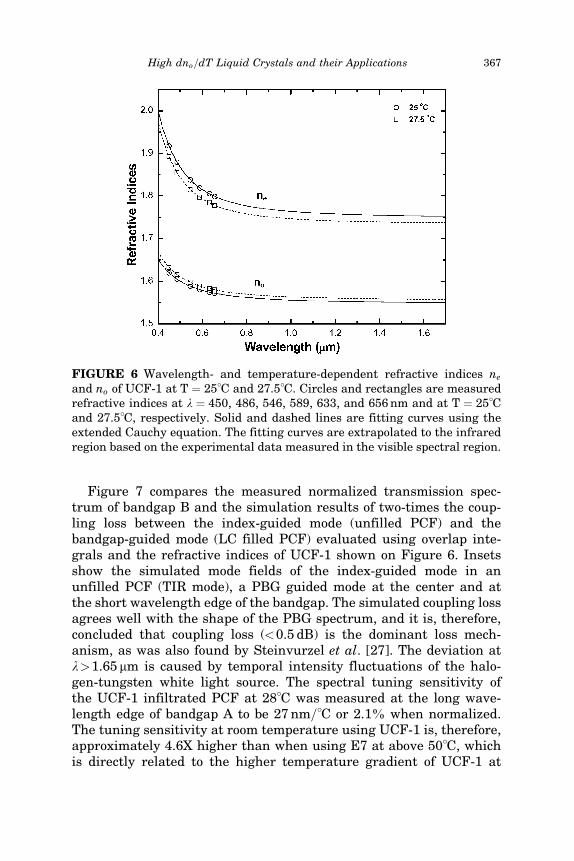
Figure 7 compares the measured normalized transmission spec-trum of bandgap B and the simulation results of two-times the coup-ling loss between the index-guided mode (unfilled PCF) and thebandgap-guided mode (LC filled PCF) evaluated using overlap inte-grals and the refractive indices of UCF-1 shown on Figure 6. Insetsshow the simulated mode fields of the index-guided mode in anunfilled PCF (TIR mode), a PBG guided mode at the center and atthe short wavelength edge of the bandgap. The simulated coupling lossagrees well with the shape of the PBG spectrum, and it is, therefore,concluded that coupling loss (<0.5 dB) is the dominant loss mech-anism, as was also found by Steinvurzel et al. [27]. The deviation atk>1.65 mm is caused by temporal intensity fluctuations of the halo-gen-tungsten white light source. The spectral tuning sensitivity ofthe UCF-1 infiltrated PCF at 28�C was measured at the long wave-length edge of bandgap A to be 27 nm=�C or 2.1% when normalized.The tuning sensitivity at room temperature using UCF-1 is, therefore,approximately 4.6X higher than when using E7 at above 50�C, whichis directly related to the higher temperature gradient of UCF-1 at
FIGURE 6 Wavelength- and temperature-dependent refractive indices ne
and no of UCF-1 at T ¼ 25�C and 27.5�C. Circles and rectangles are measuredrefractive indices at k ¼ 450, 486, 546, 589, 633, and 656 nm and at T ¼ 25�Cand 27.5�C, respectively. Solid and dashed lines are fitting curves using theextended Cauchy equation. The fitting curves are extrapolated to the infraredregion based on the experimental data measured in the visible spectral region.
High dno=dT Liquid Crystals and their Applications 367

room temperature as compared to E7 shown in Figure 8. The tempera-ture gradient at k ¼ 589 nm was calculated using a four-parametermodel [16] for describing the temperature effect on the LC refractive
FIGURE 7 Transmission spectrum of the UCF-1 filled PCF (solid line) andsimulated coupling loss (dotted line) from the index-guiding to the bandgap-guiding part of the PCF. Insets show an index-guided mode and PBG guidedmodes at the bandgap center and edge.
FIGURE 8 dno=dT and �dne=dT for E7 and UCF-1 calculated at k ¼ 589 nm.
368 J. Li et al.
indices. The four parameters were obtained by fitting the temperaturedependent LC refractive indices measured at temperature from 15 to55�C with a 5�C interval and at k ¼ 589 nm.
V. CONCLUSIONS
We have analyzed the factors affecting the dno=dT of a LC material.High birefringence and low clearing temperature are the two mostcritical parameters. Based on these simple guidelines, we formulatedtwo exemplary high birefringence and low clearing temperature LCmixtures, UCF-1 and UCF-2, using the laterally substituted isothio-cyannato tolane compounds. The dno=dT of UCF-1 is about 4X higherthan that of 5CB at room temperature. Moreover, the melting tem-perature of UCF-1 and UCF-2 is below �20�C, which is much lowerthan that of 5CB and 6CB.
The new high dno=dT LC mixtures greatly improve the thermaltuning sensitivity of liquid crystal photonic crystal fibers. A highlytunable single mode photonic bandgap fiber device has been demon-strated, which utilizes a three-rod core PCF infiltrated with UCF-1in order to obtain a large mode area and high tuning sensitivity.The guided mode has an effective area of 440 mm2 with an insertionloss of less than 0.5 dB. The loss is mainly attributed to coupling lossesbetween the index-guided section and the bandgap-guided section. Thethermal tuning sensitivity of the spectral position of the bandgap wasmeasured to be 27 nm=�C at near room temperature. The tuning sen-sitivity is 4.6�higher than that infiltrated with E7, operated at a tem-perature above 50�C.
REFERENCES
[1] Wu, S. T. & Yang, D. K. (2001). Reflective Liquid Crystal Displays, Wiley: New York.[2] Stupp, E. & Brennesholtz, M. (1999). Projection Display, Wiley: New York.[3] Alt, P. M. (1997). Conference record of the Int’l Display Research Conf. M19–28.[4] Fan-Chiang, K. H., Wu, S. T., & Chen, S. H. (2005). J. Display Technology, 1, 304.[5] McManamon, P. F., Dorschner, T. A., Corkum, D. L., Friedman, L., Hobbs, D. S.,
Holz, M., Liberman, S., Nguyen, H. Q., Resler, D. P., Sharp, R. C., & Watson, E. A.(1996). Proc. of the IEEE, 84, 268.
[6] Soref, R. A. (1979). Opt. Lett., 4, 155.[7] Hirabayashi, K., Wada, M., & Amano, C. (2001). J. Lighwave Techn., 13, 609.[8] Warenghem, M., Henninot, J. F., & Abbate, G. (1998). Opt. Express, 2, 483.[9] Warenghem, M., Henninot, J. F., Derrin, F., & Abbate, G. (2002). Mol. Cryst. Liq.
Cryst., 373, 213.[10] Larsen, T. T., Bjarklev, A., Hermann, D. S., & Broeng, J. (2003). Opt. Express, 11, 2589.[11] Alkeskjold, T. T., Lægsgaard, J., Bjarklev, A., Hermann, D. S., Anawati, A., Li, J., &
Wu, S. T. (2004). Opt. Express, 12, 5857.
High dno=dT Liquid Crystals and their Applications 369

[12] Alkeskjold, T. T., Lægsgaard, J., Bjarklev, A., Hermann, D. S., Broeng, J., Li, J.,Gauza, S., & Wu, S. T. (2005). Applied Optics., 45, 2261.
[13] Li, J., Gauza, S., & Wu, S. T. (2004). Opt. Express, 12, 2002.[14] Vuks, M. F. (1966). Opt. Spektrosk., 20, 644.[15] Haller, I. (1975). Prog. Solid State Chem., 10, 103.[16] Li, J., Gauza, S., & Wu, S. T. (2004). J. Appl. Phys., 96, 19.[17] Li, J., Wen, C. H., Gauza, S., Lu, R., & Wu, S. T. (2005). J. Display Technology, 1, 51.[18] Wu, S. T. & Lim, K. C. (1987). Appl. Opt., 26, 1722.[19] Gauza, S., Wang, H., Wen, C. H., Wu, S. T., Seed, A. J., & Da̧browski, R. (2003).
Jpn. J. Appl. Phys., Part 2, 42, 3463.[20] Pohl, L. & Finkenzeller, U. (1990). Liquid Crystals: Applications and Uses, World
Scientific: Singapore.[21] Eggleton, B. J., Kerbage, C., Westbrook, P. S., Windeler, R., & Hale, A. (2001). Opt.
Express, 9, 698.[22] Mortensen, N. A., Nielsen, M. D., Folkenberg, J. R., Petersson, A., & Simonsen, H. R.
(2003). Opt. Lett., 28, 393.[23] Dai, J. D. & Jen, C. K. (1991). J. Opt. Soc. Am. A, 8, 2021.[24] Li, J. & Wu, S. T. (2004). J. Appl. Phys., 95, 896.[25] Li, J. & Wu, S. T. (2004). J. Appl. Phys., 96, 170.[26] Li, J., Wu, S. T., Brugioni, S., Faetti, S., & Meucci, R. (2005). J. Appl. Phys., 97,
073501.[27] Steinvurzel, P., Kuhlmey, B. T., White, T. P., Steel, M. J., de Sterke, C. M., & Eggleton,
B. J. (2004). Opt. Express, 12, 5424.
370 J. Li et al.