high availability integration for the ecostructure - - apc … · high availability integration for...
TRANSCRIPT

High Availability Integration for the
ECOstructureResilient Blueprint
Version 1.0November 16, 2000
Prepared for:Dan Warnshuis, Cisco
Betty Baker, OracleAllen Hoke, OracleSarah Huq, Oracle
Rich Wells, EMCJason Kotsaftis, EMC
Prepared by:Stephen Giguere, APC
Rick Bansal, APCJodi Greenberg, APC

2
1.0 Introduction .................................................................................................................................. 41.1 What is the Value Add to ECOStructure? APC’s Value Proposition ....................................... 4
2.0 Datacenter Design Practices ............................................................................................................ 62.1 Power Availability Assessment ............................................................................................ 62.2 Physical Environment Availability Review ............................................................................ 62.3 Physical Environment Availability Assessment (in partnership with ComputerSite Engineering) 7
3.0 How to Select Power Protection for ECOstructure ........................................................................... 83.1 UPS Family Selection .......................................................................................................... 83.2 Creating Power Redundancy ............................................................................................... 93.3 Runtime Considerations ................................................................................................... 103.4 How to determine UPS runtime requirements based on Power Availability ......................... 103.5 Calculating Power Availability ........................................................................................... 113.6 Thermal Dissipation .......................................................................................................... 11
4.0 UPS Selection Load Calculations for ECOstructure ......................................................................... 124.1 Power Ratings for ECOstructure Network Equipment ......................................................... 124.2 Power Ratings for ECOstructure Storage Equipment .......................................................... 134.3 Power Ratings for ECOstructure Servers ............................................................................. 14
4.3.1 Power Ratings for ECOstructure - Database Clusters ............................................... 144.3.2 Power Ratings for ECOstructure - Application Servers ............................................ 144.3.3 Power Ratings for ECOstructure - Web Servers ....................................................... 15
4.4 Note on Graceful Server Shutdown ................................................................................... 154.5 Example for Totaling Power Ratings .................................................................................. 154.6 Power Protection Integration Diagram .............................................................................. 17
5.0 Silcon 3 Phase UPS Selection ........................................................................................................ 185.1 Silcon AC Site Power Requirements ................................................................................... 185.2 Creating N+1 System with Silcon ..................................................................................... 185.3 Silcon Physical Requirements ............................................................................................ 185.4 Power Distribution and Generators ................................................................................... 195.5 Installation Notes ............................................................................................................. 19
6.0 Symmetra Power Array: 4 to 16 KVA ............................................................................................ 206.1 Symmetra AC Site Power Requirements ............................................................................ 206.2 Symmetra Physical Requirements ..................................................................................... 206.3 Creating Redundancy with Symmetra ............................................................................... 216.4 Symmetra Thermal Dissipation ......................................................................................... 216.5 Power Distribution and Load Circuit breaker Requirements ................................................ 22
7.0 Symmetra Power Array Rackmount (RM): 2 to 6 KVA ................................................................... 237.1 Symmetra RM AC Site Power Requirements ...................................................................... 237.2 Creating N+1 System with Symmetra RM ......................................................................... 237.3 Symmetra RM Physical Requirements .............................................................................. 237.4 Symmetra RM Power Distribution ..................................................................................... 23
8.0 Smart-UPS: 700 – 5000VA............................................................................................................ 248.1 [V] Selecting the Correct UPS based on Input Line Voltage ................................................. 248.2 UPS Input AC Line Plug Selection: ..................................................................................... 248.3 - Determining Number of outlets and compatibility: ......................................................... 26
* Backplate Note for Customers with a Catalyst 5500 and 6500 ...................................... 278.4 Creating Redundancy with Smart-UPS ............................................................................... 28
9.0 APC UPS Accessories ................................................................................................................... 299.1 Load Segmentation and Management .............................................................................. 29
MasterSwitch plus ........................................................................................................ 29MasterSwitch VM ......................................................................................................... 29Power Receptacles ........................................................................................................ 30
Table of Contents

3
Table of Contents—Continued
9.2 Network Transient Protection ........................................................................................... 309.3 Expansion Cards .............................................................................................................. 30
Multiserver ................................................................................................................... 30Web/SNMP Card ............................................................................................................ 30Temperature and Humidity Card .................................................................................... 31Out-of-band Management Card .................................................................................... 31Scalable ........................................................................................................................ 31Relay I/O Module .......................................................................................................... 31USB .............................................................................................................................. 31
10.0 APC Software Integration ........................................................................................................... 3210.1 HP OpenView NNM ........................................................................................................ 3210.2 Oracle8i database........................................................................................................... 3210.3 CiscoWorks2000 ............................................................................................................ 3210.4 PowerChute Inventory Manager ..................................................................................... 32

4
Introduction
In the E-world where businesses can’t stop and downtime is measured in dollars, Ameri-can Power Conversion (NASDAQ:APCC), provides protection against one of the leadingcauses of data loss, hardware damage and downtime: power problems. Founded in 1981,APC is a leading provider of global, end-to-end AC and DC-based power protectionproducts and services, which include surge suppressors, uninterruptible power supplies(UPS), power conditioning equipment, related software, DC power systems design andinstallation, DC rectifiers, DC power supplies, and professional and consulting services forNonstop NetworkingTM. APC, known for Legendary ReliabilityTM, sets the standard forquality, innovation and support for power protection solutions from desktop todatacenter to entire facilities. Its comprehensive solutions, which are designed for bothhome and corporate environments, improve the manageability, availability and perfor-mance of sensitive electronic, network, communication and industrial equipment of allsizes. A UPS provides surge suppression, line filtering and instantaneous battery backuppower to protect mission-critical applications in the event of any power disturbance.
1.1 What is the Value Add to ECOStructure? APC’s Value Proposition
A key component of the current ECOStucture Initiative is a solution set which offers thehighest degree of availability with respect to people, process, and technology to yourcommon customers. As you can see in the table below, there are four layers to considerwhen planning for high availability. These key layers are apparent in every type of businesswhere availability is a concern. Every business needs a place of operations, the equipmentnecessary to operate the business, a process that is the function of the business, andemployees to help run the business.
4 Components of Availability
People
Process
Information Technology
Physical Environment
APC’s comprehensive line of global power availability products and services are an essentialcomponent for the high availability applications that EMC, Cisco and Oracle products arerunning. Research has shown that the physical network environment is an integral piece of

5
overall availability and APC is the world leader in protecting networking infrastructuresfrom environmental disturbances, specifically in respect to power related disturbances.
APC will add value to the ECOstructure initiative by providing the appropriate, compre-hensive power availability solution designed to help increase the overall availability ofECOstructure client solutions. The following table outlines the significant impact thatpower problems can have on system uptime. The downtime associated with powerproblems highlights the essential role power availability solutions play in achieving ahighly available networking environment. ECOstructure client solutions will benefit fromAPC’s industry leading expertise and breadth of solutions addressing this serious threat toavailability.
Percentage of Companies who Experienced Business Downtime Due toIdentified Problems
Power 72.2%Computer Hardware 52.2%Telecom Failure 46.0%Software 43.1%Human Error 34.4%Lightning 33.7%
Source: Contingency Planning Management Magazine ’97 www.ContingencyPlanning.com.

6
Datacenter Design Practices
Prior to installing an ECOstructure solution, the physical infrastructure, including power,cooling and security must be reviewed and established, to insure that any new installa-tions will not overload existing systems.
APC recommends the following services:
2.1 Power Availability Assessment
APC’s Power Availability Assessment helps improve the power availability of businessprocesses by assessing the existing power infrastructure and recommending methods ofreaching an optimal availability level.
Qualified engineers will analyze the existing power infrastructure, including the powerdistribution path, extended outage and UPS protection, and power management strategy.This onsite inspection is conducted to verify the actual level of power availability for abusiness process. The key drivers of availability are identified and a custom solution isdeveloped, by a specialized APC engineering design team, to optimize the level of poweravailability for the business process.
The detailed findings and proposed solution are presented in a comprehensive report.
2.2 Physical Environment Availability Review
APC’s Physical Environment Availability Review helps avoid downtime by identifyingpotential risks within the physical environment of a datacenter.
Qualified engineers will review twenty-seven categories of site infrastructure factorsimpacting computer hardware reliability and uptime including poor-quality power, inad-equate cooling performance, and other conditions that otherwise might go undetected.We will also look at human factors and site infrastructure management practices. Expertsperform the review with extensive backgrounds in site failure investigation and relatedhuman factors. Their expert knowledge is complemented by comprehensive test equip-ment for measuring actual raised-floor performance. Detailed findings are presented in acomprehensive report. Conclusions are summarized in an easily understood format usinga red-yellow-green color rating system.

7
2.3 Physical Environment Availability Assessment (in partnership withComputerSite Engineering)
APC’s Physical Environment Availability Assessment improves the overall physical environ-ment availability of datacenters by identifying interacting points of failure and suggestingmodifications to improve the availability.
Experienced engineers will conduct a detailed physical inspection of all subsystems thatcomprise a site’s environmental infrastructure. They assess the likelihood of downtimeevents and problems that would impede a successful recovery should an emergencyoccur. A strategy is then developed to mitigate existing vulnerabilities.
Experienced uptime professionals perform the assessment using the latest data collectiontools, plus proprietary review and analysis systems. This comprehensive assessment resultsin a detailed report that includes a scorecard for each infrastructure subsystem withrecommendations identifying the actions necessary to change a red or yellow ratedsubsystem to a green rating.

8
How to Select Power Protection for ECOstructure
ECOstructure equipment can be divided into 5 general categories: Network, Storage, WebServers, Applications Servers and Database servers. In the flexible ECOstructure environ-ment, a site will have equipment from each category.
While the equipment at each ECOstructure site may vary, the UPS selection criteria willstay consistent.
There is a seven-step process for UPS selection:
Step 1: Determine Power requirements for each site, allowing margin for future expan-sion. Tables with power consumption information of recommended ECOstructure equip-ment are listed in section 4: UPS Load Calculations for ECOstructure.
Step 2: Determine the site voltage and circuit breaker requirements. Determine if anyequipment requires 208 Vac or 3 phase (the larger EMC Symmetrix systems are 3 phase).
Step 3: Define redundancy requirements. If N+1 power protection is required, defineoptimal method for UPS deployment to achieve redundancy.
Step 4: Determine UPS space requirements. Both the SMART-UPS (700VA to 5000 VA) andthe Symmetra RM (2 KVA to 6 KVA) are available in 19” rackmount models. The Symmetra(4KVA – 16 KVA N+1) and 3-phase Silcon family are free standing systems.
Step 5: Determine AC receptacle, Power Distribution Units (PDUs) and circuit breakerrequirements.
Step 6: Determine Runtime Requirements: In the event of a power outage, how long willthe system be required to run to 1) continue functioning and 2) provide a graceful shut-down.
Step 7: Determine additional needs. APC offers hardware accessories as well as softwarefeatures to offer complete power and facility infrastructure management. Software andSMARTaccessories are discussed in section 9: APC UPS Accessories and section 10: APCSoftware Integration.
3.1 UPS Family Selection
APC offers four power protection UPS product lines for the ECOstructure. The recom-mended UPS model is determined by the load, site voltage and runtime requirements.
• Silcon 3-Phase System• Symmetra 4 KVA to 16 KVA Power Array• Symmetra RM 2 to 6 KVA Power Array• SMART-UPS 700 to 5000 VA

9
Add Step DownXformer for 120 Vac
The following flowchart will help differentiate the families.
UPS Family Selection Flowchart
Yes
Yes
Yes
120 Vac 208 Vac Yes
Determine ECOstructurePower & Voltage requirements
3 Phase equipment?
Power required > 1180Watts?
Power required between4200 & 1180 Watts?
Equipment VoltageRequirements
SMART-UPS
Use APCRedundantSwitch fordual feeds
ModularN+1 System
SMART-UPST Series
Add Step DownXformer for 120 Vac
SymmetraRMPower Array
Silcon 3 Phase UPS
Silcon 3 Phase UPS
Symmetra Power Array
APC / 11/1/00
3.2 Creating Power Redundancy
Each UPS family can be configured to create N+1 power systems. The Symmetra PowerArray’s modular architecture designed for N+1 power and battery redundancy while the3-phase Silcon system utilizes external synchronization modules to create N+1 redun-dancy. The SMART-UPS family uses an additional product called a Redundant Switch tocreate N+1 power redundancy.
Modularity and scalability are discussed in detail in the specific product sections (sections5–8).

10
3.3 Runtime Considerations
For mission critical applications where long runtimes are essential, a UPS with expandable,extended-run power is recommended. Achieving 99.999% uptime requires a UPS with aruntime of greater than one hour or the addition of a generator.
The given runtime of a UPS is directly related to the input load. There are a couple ways toachieve the desired runtime:
1) In many cases, extended run capability is achieved by over-sizing the UPS itself.2) Runtime can be added by simply plugging in additional battery packs. The Smart-
UPS XL increases availability with N+1 batteries. Extended battery packs runningin parallel with internal batteries provide both extended runtime and redundancyif a battery should fail. Smart-UPS battery packs are hot-swappable so you neverhave to take down your mission-critical load(s) to service the unit.
The following graph shows the typical runtime based on the loading percentage of the UPS.
3.4 How to Determine UPS Runtime Requirements Based on Power Availability
APC offers the Availability Profiler™, which is a tool designed to estimate both the poweravailability level and the cost of downtime of key business processes. The profile question-naire covers geography, site, building, and process questions. Using the results, theAvailability Profiler tool extrapolates how many power problems would have been avoidedif a UPS were used to protect computer equipment.
Based on these inputs, the profile will illustrate the power availability from the servicepanel entrance, to the point of consumption, to the components that make up theprocess, and to the overall business process. This information is then used to recalculatethe power availability based on a given UPS runtime and computer reboot time.
11
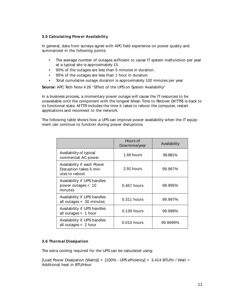
3.5 Calculating Power Availability
In general, data from surveys agree with APC field experience on power quality andsummarized in the following points:
• The average number of outages sufficient to cause IT system malfunction per yearat a typical site is approximately 15.
• 90% of the outages are less than 5 minutes in duration.• 95% of the outages are less than 1 hour in duration• Total cumulative outage duration is approximately 100 minutes per year
Source: APC Tech Note #26 “Effect of the UPS on System Availability”
In a business process, a momentary power outage will cause the IT resources to beunavailable until the component with the longest Mean Time to Recover (MTTR) is back toits functional state. MTTR includes the time it takes to reboot the computer, restartapplications and reconnect to the network.
The following table shows how a UPS can improve power availability when the IT equip-ment can continue to function during power disruptions.
3.6 Thermal Dissipation
The extra cooling required for the UPS can be calculated using:
[Load Power Dissipation (Watts)] × [100% - UPS efficiency] × 3.414 BTU/hr / Watt =Additional heat in BTU/Hour
Availability of typicalcommercial AC power
Availability if each PowerDisruption takes 5 min-utes to reboot
Availability if UPS handlespower outages < 10minutes
Availability if UPS handlesall outages < 30 minutes
Availability if UPS handlesall outages < 1 hour
Availability if UPS handlesall outages < 2 hour
Hours ofDowntime/year
1.66 hours
2.91 hours
0.467 hours
0.311 hours
0.139 hours
0.010 hours
Availability
99.981%
99.967%
99.995%
99.997%
99.998%
99.9999%

12
UPS Selection Load Calculations for ECOstructure
ECOstructure implementations can include both a Primary and a Secondary Site. Both siteswill require power protection but secondary sites may have less stringent runtime orredundancy requirements.
The following tables contain power consumption and AC plug information for the typicalequipment found in ECOstructure installations. Power information not included in thesetables can be found either from APC’s technical specifications or from the APC UPSSelector guide.
The APC Technical Specification Guide can be found on the web at http://www.apcc.com/support/tech_notes.cfm. The APC Sizing Guide can be found on the web at http://www.apcc.com/sizing/
4.1 Power Ratings for ECOstructure Network Equipment
This section summarizes the power requirements for the recommended Cisco Systemsnetwork equipment.
Summary of Power Requirements for RecommendedECOstructure Network Equipment
Power(Watts)
360
214
257
257
70
267
18003200TBD
370
Model and part number
Cisco PIX Firewall
Cisco Local Director
Cisco 2501 DistributedDirectors
Cisco 4700M DistributedDirector
Cisco 2908XL
Cisco 2900
Catalyst 6000 seriesW/ 1300 suppliesW/ 2500 suppliesW/ 4000 W supplies
Cisco 7200 SeriesRouters
Voltage
120 Vac
120
120 or 208
120 or 208
120
120
120 Vac208 Vac
120
Number ofline cords
1
1
1
1
1
12 supplies
2 supplies
AC plugtype
5-15
5-15
5-15
5-15
5-15
5-15
5-20L6-20
5-15

13
4.2 Power Ratings for ECOstructure Storage Equipment
ECOstructure recommends the EMC Symmetrix storage family. However, the particularmodel and storage requirements are application specific. The following table summarizesthe power and connector ratings for the EMC Symmetrix family.
The Symmetrix System is the largest product in the ECOstructure system and will dictatewhether the UPS is a single or 3-phase system.
Summary of Power Requirements for RecommendedECOstructure Storage Equipment
MaximumPhysicalVolumes
32
96
32
128
128
96
256
EMC SymmetrixModel and partnumber
3330-185330-18
3430-185430-18
3630 series5600 series
3700-185700-18
3700-475700-47
3830 series5830 series8430 series
3930 series5930 series8730 series
MaximumPower
(Watts)
1516
3527
1585
5480
7049
3714
9679
Voltage
208 Vac
208 Vac
208 Vac
208 Vac 3phase 4 wire
208 Vac 3phase 4 wire
208 Vac
208 Vac 3phase 4 wire
Numberof linecords
2
2
2
2
2
2
2
AC plug type
Russellstoll3913 (flex) or3743 (rigid)
Russellstoll3933 (flex) or3753 (rigid)
Russellstoll3913 (flex) or3743 (rigid)
Russellstoll3934 (flex) or3754 (rigid)
Russellstoll3934 (flex) or3754 (rigid)
Russellstoll3933 (flex) or3753 (rigid)
Russellstoll9C54U2 (flex)or 9R54U2W(rigid)
Note: For 208 Vac installations, a licensed electrician will be required to change theSymmetrix line plug to an L6-20 or L6-30.

14
4.3 Power Ratings for ECOstructure Servers
From a UPS sizing perspective, the open standard on the server selection makes the powerconsumption calculations more challenging.
4.3.1 Power Ratings for ECOstructure - Database Cluster Servers
There should be at least two database cluster servers in the ECOstructure blueprint. Thedatabase cluster servers will most likely be UNIX with an abundance of RAM (Oracle 8iminimum requirements are 128 MB but 2-4 GB is recommended). Each system should bemultiprocessor (4 CPUs or more) with 2 to 4 disk drives, a CD-ROM as well as numerousexpansion slots for NIC cards.
The following table is a summary of potential servers used as ECOstructure DatabaseCluster Servers.
4.3.2 Power Ratings for ECOstructure - Application Servers
There should be at least two Application Servers in the ECOstructure blueprint. TheApplication servers will most likely be UNIX, LINUX or NT with an abundance of RAM (1-2GB is recommended). Each system should be multiprocessor (2 CPUs or more) with 2 to 4disk drives, as well as numerous expansion slots for NIC cards.
The following table is a summary of potential servers used as ECOstructure ApplicationServers.
Model and partnumber
White Box serverwith 2 CPU’s & 2disk drives
Sun Enterprise 450
HP NetServerLH4/LH4r
Power(Watts)
388
1148
1076
Voltage
120 Vac
120 or 208
120 or 208
Number ofline cords
1
1
1
AC plugtype
5-15
5-15
5-20
Model and partnumber
White Box serverwith 4 CPU’s & 2disk drives
Sun Enterprise 450
HP NetServerLH4/LH4r
Power(Watts)
468
1148
1076
Voltage
120 Vac
120 or 208
120 or 208
Number ofline cords
1
1
1
AC plugtype
5-15
5-15
5-20

15
4.3.3 Power Ratings for ECOstructure - Web Servers
There will typically be a 1 to 1 ratio of Web to Application Servers in the ECOstructureblueprint. The Web servers do not require multiple processors but need 2 to 4 disk drives,as well as numerous expansion slots for NIC cards.
The following table is a summary of potential servers used as ECOstructure Web Servers.
4.4 Note on Graceful Server Shutdown
Gracefully shutting down servers is important to preserve the data integrity and reducetotal cost of ownership. However, The ECOstructure environment does not specify thenumber of servers or even the operating systems.
APC offers hardware and software solutions for graceful shutdowns in a mixed environ-ment. The hardware solution is the APC Share-UPS that can provide shutdown capabilityfor up to eight servers. The software solution works over the network. APC’s PowerChuteNetwork Shutdown software works in conjunction with APC’s Web/SNMP ManagementCard to provide graceful, unattended shutdown of multiple computer systems over anetwork. Its scalable architecture can support a virtually unlimited number of clientsystems. Administrators can quickly configure the software via a browser-based interface,and can customize command files to run on each server in the event of an unattendedshutdown
4.5 Example for Totaling Power Ratings
The following example illustrates how to determine the power requirements for anECOstructure configuration:
Model and partnumber
White Box serverwith 2 disk drives
Sun Enterprise 450
HP NetServerLH4/LH4r
Power(Watts)
334
1148
1076
Voltage
120 Vac
120 or 208
120 or 208
Number ofline cords
1
1
1
AC plugtype
5-15
5-15
5-20

16
Primary Site
Network
Servers
Storage
Model
Cisco 2908XLDistributedDirectorsLocalDirectorsCatalyst 6500Catalyst 7200PIX Firewalls
Web ServersApplicationServersClusterDatabaseServers
Symmetrix3430-18
Power
70257
214
3200370360
334388
468
3527
Quantity
32
2
222
22
2
1
Plug
5-155-15
5-15
L6-20 208 Vac5-155-15
5-155-15
5-15
Russellstoll
Total
210514
428
6400740720
668776
936
3527
14919 Watts
Secondary Site
Network
Servers
Storage
Model
Cisco 2908XLDistributedDirectorsLocalDirectorsCatalyst 6500Catalyst 7200PIX Firewalls
Web ServersApplicationServersClusterDatabaseServers
Symmetrix3430-18
Power
70257
214
3200370360
334388
468
3527
Quantity
11
1
112
22
2
1
Plug
5-155-15
5-15
L6-20 208 Vac5-155-15
5-155-15
5-15
Total
70257
214
3200370360
334388
468
3527
9188 Watts
17
For the primary site, the recommended UPS to support a load close to 15,000 watts is a 3-phase Silcon system. The customer could select a single 20 KVA UPS system or three 10KVA systems to support N+1 redundancy.
For the secondary site, the recommended UPS to support a 9,200 Watt load is the APCSymmetra power Array. The customer can add additional power and battery modules forredundancy.
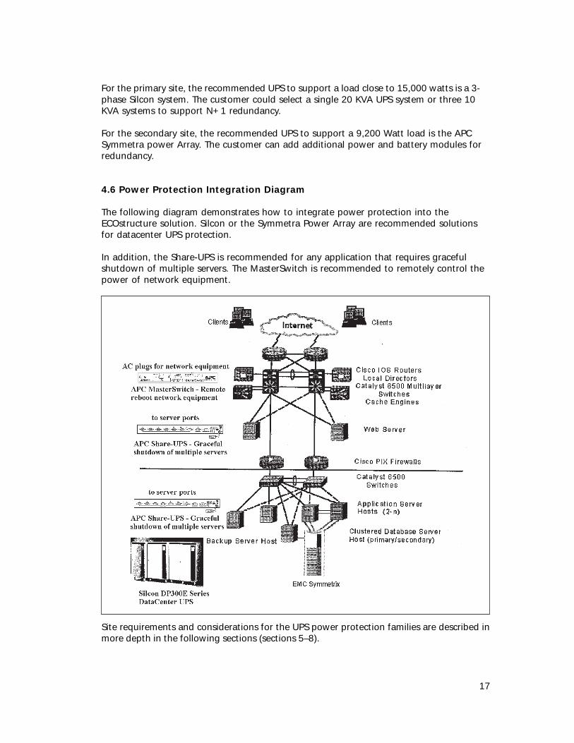
4.6 Power Protection Integration Diagram
The following diagram demonstrates how to integrate power protection into theECOstructure solution. Silcon or the Symmetra Power Array are recommended solutionsfor datacenter UPS protection.
In addition, the Share-UPS is recommended for any application that requires gracefulshutdown of multiple servers. The MasterSwitch is recommended to remotely control thepower of network equipment.
Site requirements and considerations for the UPS power protection families are described inmore depth in the following sections (sections 5–8).

18
Silcon 3-Phase UPS Selection
Silcon is an on-line, high efficiency UPS technology. It provides maximum protectionagainst spikes surges, brownouts and blackouts while providing a power factor correctedinput to the utility. It is designed specifically to protect datacenters starting at 10 KVA.
5.1 Silcon AC Site Power RequirementsSilcon units in the 10 to 80 KVA range can be powered from either 208 Vac or 480 Vac.Silcon units 100 KVA and above require 480 Vac.
5.2 Creating N+1 System with Silcon
Up to nine Silcon systems can be paralleled to serve special demands for scalability andredundancy.
5.3 Silcon Physical Requirements
Power Rating
KW, KVA120160240320400500
Dimensions
H×W×D (in)70.87×62.99×31.5070.87×62.99×31.5070.87×74.80×31.5070.87×74.80×31.5070.87×94.49×31.5070.87×94.49×31.50
Floor Loading
(lbs/in2)9.359.3513.4613.4613.3913.39
Heat Dissipation
(kBTU/hr)23.20225.59044.01549.13353.91065.510
Weight
(lbs)308030804432443255125512

19
5.4 Power Distribution and Generators
The following diagram illustrates how a back-up diesel generator can be incorporated intothe power protection strategy.
5.5 Installation Notes
Installation of a 3-phase UPS usually requires a power specialist or dedicated electricalcontractor who is has in-depth knowledge of 3-phase issues and the National ElectricalCode requirements.
20
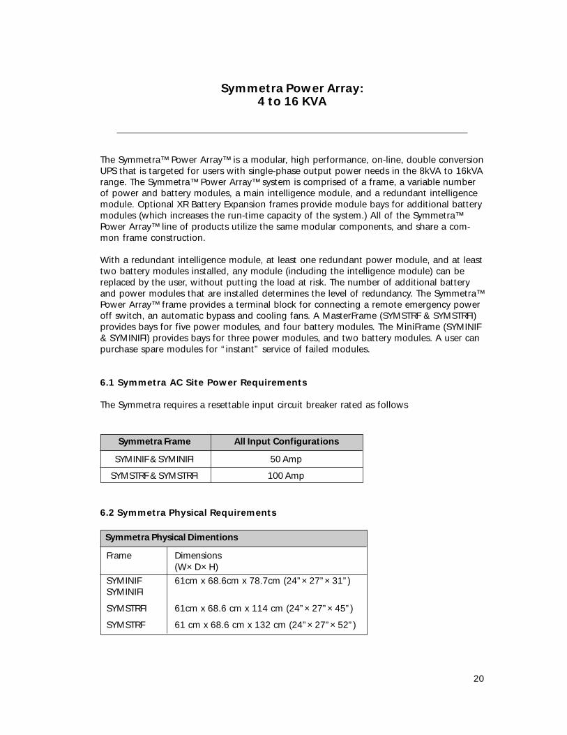
Symmetra Power Array:4 to 16 KVA
The Symmetra™ Power Array™ is a modular, high performance, on-line, double conversionUPS that is targeted for users with single-phase output power needs in the 8kVA to 16kVArange. The Symmetra™ Power Array™ system is comprised of a frame, a variable numberof power and battery modules, a main intelligence module, and a redundant intelligencemodule. Optional XR Battery Expansion frames provide module bays for additional batterymodules (which increases the run-time capacity of the system.) All of the Symmetra™Power Array™ line of products utilize the same modular components, and share a com-mon frame construction.
With a redundant intelligence module, at least one redundant power module, and at leasttwo battery modules installed, any module (including the intelligence module) can bereplaced by the user, without putting the load at risk. The number of additional batteryand power modules that are installed determines the level of redundancy. The Symmetra™Power Array™ frame provides a terminal block for connecting a remote emergency poweroff switch, an automatic bypass and cooling fans. A MasterFrame (SYMSTRF & SYMSTRFI)provides bays for five power modules, and four battery modules. The MiniFrame (SYMINIF& SYMINIFI) provides bays for three power modules, and two battery modules. A user canpurchase spare modules for “instant” service of failed modules.
6.1 Symmetra AC Site Power Requirements
The Symmetra requires a resettable input circuit breaker rated as follows
Symmetra Frame
SYMINIF & SYMINIFI
SYMSTRF & SYMSTRFI
All Input Configurations
50 Amp
100 Amp
6.2 Symmetra Physical Requirements
Symmetra Physical Dimentions
Frame
SYMINIFSYMINIFI
SYMSTRFI
SYMSTRF
Dimensions(W×D×H)61cm x 68.6cm x 78.7cm (24”×27”×31”)
61cm x 68.6 cm x 114 cm (24”×27”×45”)
61 cm x 68.6 cm x 132 cm (24”×27”×52”)

21
Symmetra — WeightsComponent
SYMINIFSYMSTRFSYMINIFISYMSTRFI
312 lb540 lb180 lb340 lb
62 lb
33 lb
7 lb
208/240 Vac,60 Hz (Emptyframe)
220/230/240,50/60 Hz(Empty frame)
Battery Module
Power Module
MIM (or RIM)
Net Weight338 lb558 lb205 lb388 lb
69 lb
40 lb
9 lb
Shipping Weight
6.3 Creating Redundancy with Symmetra
The modular nature of the Symmetra Power Array allows considerable flexibility in userconfiguration and service. Because the output power is derived from a user-definednumber of 4kVA power modules, a user can increase the power capacity of the SymmetraPower Array by adding hot-pluggable power modules. In a similar manner, adding hot-pluggable battery modules can increase runtime. The parallel connection of power andbattery modules provides fault tolerance for the Symmetra system itself. By adding onepower module more than is required to power the load, the Symmetra Power Arraybecomes a redundant (N+1) power source. With this configuration, any one powermodule can fail and the load is still provided with basic UPS protection.
6.4 Symmetra Thermal Dissipation
The following table gives typical thermal dissipation for a fully functioning SymmetraPower Array system. Note that heat production and output is significantly higher whilethe batteries are charging. Under normal operating conditions, battery recharge periodsare relatively infrequent.
SYMINIF
SYMINIFI
SYMSTRF
SYMSTRFI
BTU/Hr(batteries fully charged)
3,413
2,321
6,826
4,642
BTU/Hr(batteries charging, full frame capacity with
N+1 module configuration)
8.670
7,578
15,640
13,456

22
6.5 Power Distribution and Load Circuit breaker Requirements
Due to the difference in available current capacity and the maximum current rating ofprovided output receptacles, the Symmetra can be provided with an optional powerpanel. The power panels provide output receptacles with user-resettable circuit breakers.The ratings of these protectors are listed as follows.
Receptacle Type
NEMA 5-15R
IEC 320 C13
L14-30R
Circuit Breaker Rating
15 Amp
12 Amp
2-pole, 25 Amp (model 3000)2-pole, 30 Amp (model 5000)

23
Symmetra Power Array:Rackmount (RM) 2 to 6 KVA
While most ECOstructure implementations will require DataCenter sized power protec-tion, there may also be a need for smaller rackmount UPS solutions. The Symmetra RM isbased on the larger Symmetra Power Array functionality, except it has 2 KVA powermodules and is designed specifically for rack environments.
7.1 Symmetra RM AC Site Power Requirements
Symmetra RM requires a 30 amp 208 Vac service.
7.2 Creating N+1 System with Symmetra RM
The Symmetra RM power modules can be added for scalability or redundancy.
7.3 Symmetra RM Physical Requirements
Symmetra RM Physical Specifications
14"×19"×28.75" (with bezel)
Approximately 294 lbs
Typical 1290 at full load.3300 with batteries charging
Dimensions (H×W×D)
Weight — fully loaded
Heat Dissipation
7.4 Symmetra RM Power Distribution
The Symmetra RM has 2 L6-20 and 1 L6-30 outlet.

24
SMART-UPS:700 – 5000KVA
The Smart-UPS is a line interactive UPS family with a line of products in the 700 VA to5000VA range. While the recommended ECOstructure solution is a DataCenter UPS, aSmart-UPS is an ideal solution for any part of ECOstructure outside the data center.
8.1 [V] Selecting the Correct UPS based on Input Line Voltage
UPS models are optimized for specific site voltages. The following table summarizesnominal voltage rating:
Notes
Domestic
International
Telco / 2 phase
Japan
Nominal Voltage
110 to 120 Vac
220 to 240 Vac
208 Vac
100 Vac
[V] – Site Voltage
I
T
J
Check country specific requirements in APC Technical Note #T13 “International Line VoltageSpecifications” for country specific site voltage requirements.
8.2 UPS Input AC Line Plug Selection:
A customer may replace the standard AC input line plug with a different UL recognizedplug. However, the customer must take care to ensure that the plug meets the NationalElectric Code requirements.
Important tip: The NEC (NFPA 70 National Electrical Code) section 210-21 lists the limitsfor AC plugs and receptacles (80% of a plug’s current rating at nominal voltage). Forexample, if a UPS has a 20 amp input plug then the maximum steady state input current is16 Amps.
Larger UPS (2200VA or greater) may require an AC input plug different from the standardAC plug shipped with the UPS.
A unit that has been purposely oversized for extended runtime or for future expansion,may require a larger AC input plug. When planning to install a 120V version of the Smart-UPS models 2200 or 3000, care must be taken to insure that the proper receptacle isavailable at the installation site, with respect to the plug that ships with the unit.

25
The following tables show the rating for each plug, as well as the optional plugs that canbe attached to each unit.
Note: Items in bold-face are the standard.
UPS Maximum VA Rating based on AC plug type for 120 Vac units
VA Rating
1440192019202200
28803000
192019202200
Amp Rating/Plug Type
15 Amp (5-15P)20 Amp (5-20P)20Amp (L5-20P)30 Amp (L5-30P)
30 Amp (L5-30P)50 Amp (5-50P)
20 Amp (5-20P)20 Amp (L5-20P)30 Amp (L5-30P)
APC UPS Model
SU2200 / SU2200RM
SU3000 / SU3000RM
SU2200XL / SU2200RMXL(Extended-Run Model)
Please refer to the following drawings to distinguish between various plug and receptacletypes.
Each drawing can be considered both a Plug “P” or Receptacle “R”.
The “L” refers to the Locking feature of the plug or receptacle.
The first number represents the voltage: 5 = 120 VAC 6 = 208/240 VAC
The second number represents the current: for example 15 = 15 Amps
5-15P 5-15R
5-20P 5-20R
5-30P 5-30R
5-50P 5-50R
L5-15P L5-15R
L5-20P L5-20R
L5-30P L5-30R

26
6-15P 6-15R
6-20P 6-20R
6-30P 6-30R
6-50P 6-50R
L6-15P L6-15R
L6-20P L6-20R
L6-30P L6-30R
8.3 Determining Number of Outlets and Compatibility:
Determine the quantity and type of receptacles required to power the load. Be sure totake into consideration the line amperage (15amp, 20amp, etc) and site voltage (120V,208V, 240V) requirements. The Smart-UPS SU2200 and SU3000 support optional recep-tacle backplates.
Available options include:
Standard Output Configuration:(8) NEMA 5-15R or (8) NEMA 5-15R
or

27
Optional Wiring Devices/Backplates:
For use with SU2200NET, SU2200XLNET & SU3000NET:APC Part #SU027 APC Part #SU028 APC Part #SU029(6) NEMA 5-15 (4) NEMA 5-15 (4) NEMA 5-15(1) NEMA L5-30 (4) NEMA L5-15 (2) NEMA 5-20
(1) NEMA L5-20
For use with SU2200RMNET, SU3000RMNET & SU2200RMXLNET:APC Part #SU027RM APC Part #SU028RM APC Part #SU029RM(6) NEMA 5-15 (4) NEMA 5-15 (4) NEMA 5-15(1) NEMA L5-30 (4) NEMA L5-15 (2) NEMA 5-20
(1) NEMA L5-20
For use with SU2200RM3U & SU3000RM3U:APC Part #SU027RM3U APC Part #028RM3U APC Part #SU029RM3U(6) NEMA 5-15 (4) NEMA 5-15 (4) NEMA 5-15(1) NEMA L5-30 (4) NEMA L5-15 (2) NEMA 5-20
(1) NEMA L5-20
Backplate Note for Customers with a Catalyst 5500 and 6500
The standard SMART-UPS SU2200 and SU3000 has a backplate with eight 5-15R recep-tacles. However, both the Catlyst 5500 and 6500 require a UPS with a 5-20 receptacle. Besure to order a SU2200 or SU3000 with a SU-029 backplate because the SU-029 has a 5-20receptacle.

28
8.4 Creating Redundancy with Smart-UPS
For increasing AC power availability to network equipment, APC offers the SU-041Redundant Switch that works in conjunction with two identical Smart-UPS. With dualinput power cords, Redundant Switch has the ability to source power from separate ACcircuits. The Redundant Switch continuously monitors both AC circuits and, in the eventof a power outage on the primary source, will switch automatically to the redundant ACsource. The transfer is seamless to the attached loads ensuring the availability of continu-ous AC power and safe, graceful server shutdown.

29
APC UPS Accessories
9.1 Load Segmentation and Management
APC offers its MasterSwitch™ plus and MasterSwitch VM to provide load segmentation,management and receptacle control. Other accessories such as the MasterSwitch PowerReceptacles provide switching for various voltage and load ratings.
MasterSwitch plus
MasterSwitch plus is a 1U rack-mountable power control unit (PCU) that facilitates powermanagement to as many as eight servers or peripherals. Control interfaces forMasterSwitch plus include telnet, HTTP, and RS-232.
MasterSwitch plus allows the administrator to manage power on-demand, with opera-tions including On, Off, Delayed On/Off, Reboot, Graceful Shutdown/Reboot.
MasterSwitch plus is also a multi-port interface expander that allows up to eight servers tomonitor a single APC UPS. Servers connected to the eight basic signaling ports receive UPSstatus information using APC’s PowerChute power monitoring software. A single serverconnected to the advanced port can use APC PowerChute plus software to take fulladvantage of the extended capabilities of the UPS.
Each power outlet of MasterSwitch plus is independently configurable. Administrators canset up sequenced power-up and automatic load shedding. Graceful Shutdown modeensures that the server operating system is shutdown prior to cycling power. MasterSwitchplus also integrates with APC’s Measure-UPS environmental monitor to allow automatedpower management based on temperature, humidity, or simple contact closure alarmindications. User-selectable automatic reboot after power restoration is supported.
MasterSwitch VM
MasterSwitch VM is an intelligent power control unit (PCU) that provides control of powerand is optimized for the rack environment. MasterSwitch VM has eight switchable 5-15receptacles and eight always-on 5-15 receptacles in a vertically mounted PDU configuration.
MasterSwitch VM provides overload indications via an audible alarm and LED indicator aswell as outlet state indication via LEDs.
Features of MasterSwitch VM include the ability to daisy-chain up to four units togetherto permit switching of up to 32 receptacles, synchronized switching across units to permitcontrol of redundant-feed devices, and user-programmable startup delays to minimize in-rush at system startup.
A Network Controller provides flexible control options including HTTP and telnet. OptionalMD5 authentication and multiple user/password pairs permit administrators to assignoutlet groups to individual users.

30
Power Receptacles
MasterSwitch plus and MasterSwitch VM can be used in conjunction with theMasterSwitch Power Receptacles for switching larger loads or loads with different voltagerequirements. These optional Power Receptacles increase the maximum load currentcontrolled by a MasterSwitch unit by allowing loads to be shifted from the MasterSwitchto a separate branch circuit.
A variety of power receptacles is available in a 2U configuration, with an optional rack-mount tray available.
9.2 Network Transient Protection
Network transient protection is provided by APC’s PNET1, which can be bundled into theCisco, customized packages. APC’s PNET1 protects datalines from transients and protects10BaseT, 100BaseT, Token Ring etc.
9.3 Expansion Cards
Multiserver
APC’s Share-UPS & SmartSlot Interface Expander provides data protection for multipleservers on one UPS. For managing multiple servers, particularly in a mixed OS environ-ment, SmartSlot Interface Expander and Share-UPS are essential tools to properly managesignaling servers from a single UPS. Share-UPS provides management and shutdown forup to eight completely OS-independent servers to a single UPS. SmartSlot InterfaceExpander provides two additional ports to facilitate safe system shutdown and advancedUPS management of up to three servers from one UPS. All three servers can be runningdifferent operating systems, making it ideal for multiple OS environments.
Web/SNMP Card
APC’s Web/SNMP Card provides web based monitoring to enhance administrator manage-ment of APC devices protecting networking equipment in distributed network environ-ments. APC Web/SNMP Management Card is the only web based UPS Managementproduct to provide full management of UPSs via multiple open standards like Telnet/HTTP/SNMP. It is a full-featured robust power management product that is tightly integratedand certified with enterprise management products. Benefits include:
• Allows users to monitor and configure their APC UPSs• Perform user registration via the web for battery management• Perform device inventory management• Shutdown and reboot the UPS
The standard Web/SNMP card includes:• User’s Manual• Installation Disk
Note: The Web/SNMP card does not include a network cable.

31
Temperature and Humidity Card
APC’s Measure-UPS II monitors environmental conditions through the APC UPS. Sensorsfor temperature and humidity continuously monitor the environment of valuable equip-ment. User-selectable thresholds allow users to decide when they need to be notified ofpotential environmental problems to prevent damage from occurring.
Measure-UPS II offers four user-definable external inputs for use with sensors for fire,water, smoke, unauthorized entry, physical security, or any external condition that can bemeasured via contact closure. Measure-UPS II communicates information in a variety offormats to ensure that applications are supported.
Out-of-band Management Card
APC’s Call-UPS II provides remote UPS Management via a modem. With the Call-UPS II,UPS status and environmental conditions (using Measure-UPS Accessory) can be accessedremotely and easily. Users can run UPS tests, configure Call-UPS and change UPS internalparameters remotely. Call-UPS II offers extensive capabilities to re-boot “locked-up”devices safely and easily, without having to travel to the site. The power event loggingand on-line data logging capabilities of the Call-UPS II allow for easy troubleshooting andpaging capabilities for flexible remote management.
Scalable
Future enhancements to APC’s Web/SNMP Management Card will permit scalability(delivery date tba). Management cards are installed in each UPS, providing a dedicatedinterface to the network and allowing each UPS to be independently controlled, config-ured and monitored. Data and event logs for a given UPS will be generated by and storedin the corresponding management card. UPS turn on and off will be synchronized bycommunication between the various management cards and software agents.
Server shutdown will be implemented with software agents running on each individualserver. These agents can identify which management cards to monitor. Combinationallogic will be implemented to ensure that system shutdown is initiated only when at leasttwo of any critical components have failed or are imminently likely to fail. Server-specificevent logs will be generated and stored by these agents.
Relay I/O Module
APC’s SmartSlot Relay I/O Module UPS provides users with control in a dry contact envi-ronment. Critical electronic devices are only as reliable as the electricity that powers them.The SmartSlot Relay I/O Module allows users to remotely monitor the UPS battery andoperation when the power goes out. Remote installations typically require direct interven-tion to shutdown and power-on equipment. The SmartSlot Relay I/O Module gives usersthe ability to remotely startup or stop equipment via the dry contact interface, whichsaves support costs.
USB
APC offers USB support via option kits.

32
APC Software Integration
10.1 HP OpenView NNM
APC’s PowerNet Manager for HP OpenView Network Node Manager (NNM) is a fullfeatured robust power management application that is tightly integrated and certifiedwith HP OpenView. It allows users to monitor and configure their APC UPSs, as well asshutdown and reboot the UPS.
APC’s PowerNet Manager is the only UPS management application to have the HPOpenView Certified Application status. In addition, APC is an HP Portfolio Partner
10.2 Oracle8i database
PowerChute Application Shutdown Utility for Oracle on NT is a utility that allows Oracledatabase administrators to quickly configure PowerChute plus for NT to safely shutdownOracle databases in the event of a power disturbance.
APC is the only application in the UPS market to gain the On Oracle logo.
10.3 CiscoWorks2000
PowerNet for CiscoWorks 2000 is the first web based UPS Management product to pro-vide full management of APC UPSs protecting internetworking equipment and APCMasterSwitches via HTTP. It is a power management application that can be accessed via aweb browser from anywhere on the network.
PowerNet Manager for CiscoWorks2000 is the only UPS management application toreceive the CiscoWorks2000 logo.
10.4 PowerChute Inventory Manager
PowerChute Inventory Manager Extension for CiscoWorks2000 Service ManagementSolution is a browser-based inventory management and reporting tool for networkadministrators allowing them to maximize the availability of the network by maintainingthe health and efficiency of its APC UPS system. The extension allows administrators togenerate and view reports using APC PowerChute Inventory Manager based on SLA datacompiled by CiscoWorks2000 Service Management Solution.