high amplitude arbitrary/function generator simplifies...
TRANSCRIPT

High Amplitude Arbitrary/FunctionGenerator Simplifies Measurement inAutomotive, Semiconductor, Scientific and Industrial Applications
Application Note
High Amplitude Arbitrary/Function Generator Simplifies Measurement in Automotive, Semiconductor, Scientific and Industrial Applications Application Note
A number of electronic design applications require stimuli with amplitudes that exceed the capabilities of mostarbitrary/function generators available in the market today.These applications include power semiconductors, such asMOSFETs and IGBTs widely used in automotive electronicsystems and switching power supplies, amplifiers for gaschromatography and mass spectroscopy detectors, and others in science and industry.
Commonly, arbitrary/function generators provide amplitudesof up to 10 Vpp into 50 Ω loads and 20 Vpp into open circuits. The devices mentioned above often operate over an input range that is twice as large. Until now, testing thesedevices over their full operating range commonly required anamplifier to boost the signal provided by a standard generator.This increased the complexity of the test set-up, createduncertainty about the effective amplitude at the amplifier output, and added equipment cost.
This application note describes the conventional approach of generating high amplitude signals with an external amplifier.It then discusses typical applications and shows the benefitsof using a novel arbitrary/function generator with integratedhigh amplitude stage. Applications described in this noteinclude measuring the timing and switching characteristics ofpower semiconductors for automotive applications and thecharacterization of amplifiers for gas chromatography detectors.
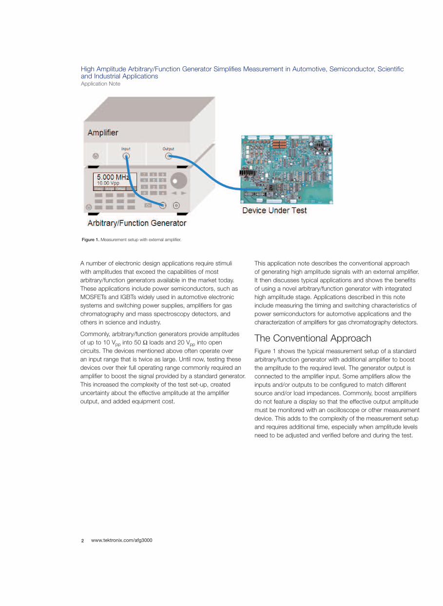
The Conventional ApproachFigure 1 shows the typical measurement setup of a standardarbitrary/function generator with additional amplifier to boostthe amplitude to the required level. The generator output isconnected to the amplifier input. Some amplifiers allow theinputs and/or outputs to be configured to match differentsource and/or load impedances. Commonly, boost amplifiersdo not feature a display so that the effective output amplitudemust be monitored with an oscilloscope or other measurementdevice. This adds to the complexity of the measurement setupand requires additional time, especially when amplitude levelsneed to be adjusted and verified before and during the test.
2 www.tektronix.com/afg3000
Figure 1. Measurement setup with external amplifier.

High Amplitude Arbitrary/Function Generator Simplifies Measurement in Automotive, Semiconductor, Scientific and Industrial Applications
Application Note
3www.tektronix.com/afg3000
Measuring Switching Time on Power MOSFETsPower MOSFETs are used in a variety of automotive motioncontrol, power management, and climate control applications.They drive small motors, solenoids, anti-lock brake, electricalpower steering and electronic stability program systems aswell as ignitor circuits for H.I.D lamps. They are also a keycomponent of integrated starter/alternators.
Figure 2 shows an example of MOSFETs used in an H-bridgetopology to drive a DC motor. This configuration provides forward, reverse and braking functions.
When used as a switch, the MOSFET's basic function is to control the drain current via the gate signal. In these applications, switching time is an important criteria consid-ered by circuit designers during the component selection. A MOSFET’s switching performance is determined by thetime required to establish voltage changes across its internalcapacitances (see Figure 3). Note that the gate-to-sourcevoltage must first charge the MOSFET’s input capacitance to its characteristic threshold level before drain current conduction can start.
Figure 2. H-bridge configuration of four MOSFETs in a DC-motor drive. Figure 3. MOSFET schematic and equivalent circuit.
High Amplitude Arbitrary/Function Generator Simplifies Measurement in Automotive, Semiconductor, Scientific and Industrial Applications Application Note
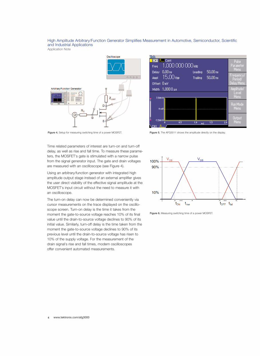
Time related parameters of interest are turn-on and turn-offdelay, as well as rise and fall time. To measure these parame-ters, the MOSFET's gate is stimulated with a narrow pulsefrom the signal generator input. The gate and drain voltagesare measured with an oscilloscope (see Figure 4).
Using an arbitrary/function generator with integrated highamplitude output stage instead of an external amplifier givesthe user direct visibility of the effective signal amplitude at theMOSFET's input circuit without the need to measure it with an oscilloscope.
The turn-on delay can now be determined conveniently viacursor measurements on the trace displayed on the oscillo-scope screen. Turn-on delay is the time it takes from themoment the gate-to-source voltage reaches 10% of its finalvalue until the drain-to-source voltage declines to 90% of itsinitial value. Similarly, turn-off delay is the time taken from themoment the gate-to-source voltage declines to 90% of itsprevious level until the drain-to-source voltage has risen to10% of the supply voltage. For the measurement of the drain signal's rise and fall times, modern oscilloscopes offer convenient automated measurements.
4 www.tektronix.com/afg3000
Figure 4. Setup for measuring switching time of a power MOSFET. Figure 5. The AFG3011 shows the amplitude directly on the display.
Figure 6. Measuring switching time of a power MOSFET.
High Amplitude Arbitrary/Function Generator Simplifies Measurement in Automotive, Semiconductor, Scientific and Industrial Applications
Application Note
5www.tektronix.com/afg3000
Analyzing the Switching Waveforms of an IGBTIn recent years, insulated gate bipolar transistors (IGBTs) have been finding increasing use in industrial and automotiveapplications as replacement of MOSFETs thanks to their highswitching speed, high current capabilities, large blocking voltages, and simple gate drive characteristics, but lowerconduction losses and lower voltage drop in the on-state.
Industrial applications for IGBTs include traction, variablespeed motor drives, uninterrupted power supplies (UPS),induction heating, welding, and high-frequency switch modepower supplies in telecom and server systems. In the auto-motive industry, IGBTs are in huge demand for ignition coildriver circuits, motor controllers, and safety related systems.
IGBTs are a cross between bipolar transistors and MOSFETs.In terms of output switching and conduction characteristics,the IGBT resembles the bipolar transistor. However, whilebipolar transistors are current controlled, IGBTs are voltagecontrolled like a MOSFET. To assure full saturation and limit short circuit current, a gate drive voltage of +15V is recommended.
Like a MOSFET, an IGBT has capacitances between gate,emitter, and collector. When voltage is applied between thegate and emitter terminals, the input capacitance is chargedup through the gate resistor RG in an exponential fashion until
the IGBT's characteristic threshold voltage is reached wherecollector-to-emitter conduction is established. Likewise, the input gate-to-emitter capacitance must be discharged to a specific plateau voltage, before collector-to-emitter conduction is interrupted, and the IGBT turns off.
The size of the gate resistor significantly impacts the dynamicturn on and turn off characteristics of the IGBT. A smallergate resistor charges and discharges the IGBT's gate-to-emitter capacitance faster, resulting in short switching timesand small switching losses. However, a small gate resistorvalue can also cause oscillations due to the gate-to-emittercapacitance of the IGBT and parasitic inductance of theleads. To reduce turn-off losses and to improve the IGBT'simmunity to noise injected through the rate of change of thecollector-to-emitter voltage which can be substantial forinductive loads, it is recommended that the gate drive circuitry includes substantial on and off biasing.
The IGBT's best performance varies by application, and thegate drive circuit must be designed accordingly. In hard-switching applications such as motor drives or uninterruptedpower supplies, the gate drive parameters must be selectedso that the switching waveform does not exceed the IGBT'ssafe operating area. This can imply a sacrifice in switchingspeed at the expense of switching loss. In soft-switchingapplications where the switching waveform is well within thesafe operating area, the gate drive can be designed for shortswitching times and lower switching loss.
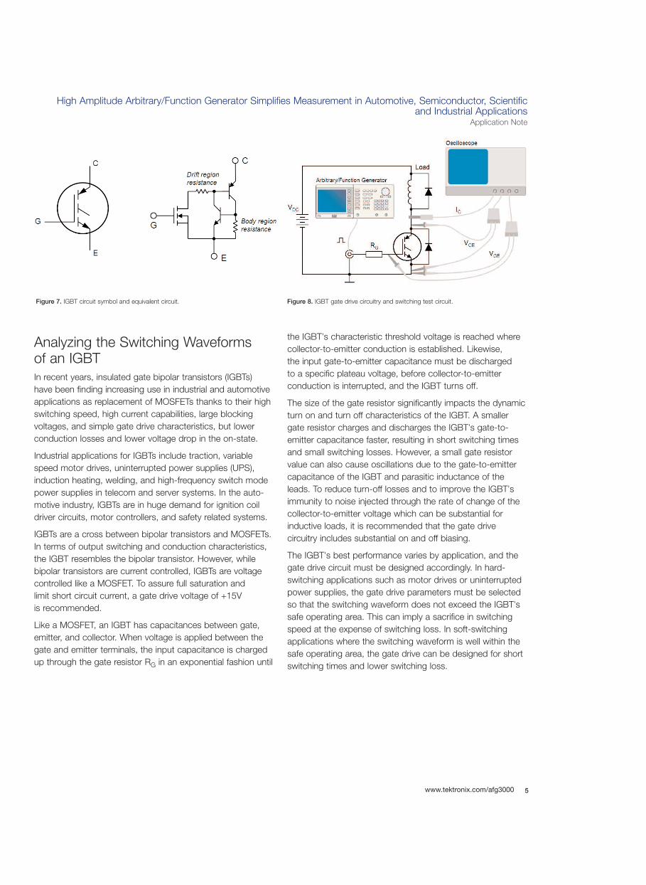
Figure 7. IGBT circuit symbol and equivalent circuit. Figure 8. IGBT gate drive circuitry and switching test circuit.

High Amplitude Arbitrary/Function Generator Simplifies Measurement in Automotive, Semiconductor, Scientific and Industrial Applications Application Note
To optimize the design of an IGBT gate drive, the design engi-neer must understand the device's switching characteristicsunder the actual load conditions. To analyze these switchingcharacteristics, the gate of the IGBT is stimulated with aseries of single pulses while the gate-to-emitter voltage, collector-to-emitter voltage and collector current are meas-ured with an oscilloscope. Thanks to its capability to generatepulses with high amplitudes, the arbitrary/function generatorAFG3011 is ideally suited for this task. Since the IGBT'scollector-to-emitter voltage has a very high dynamic range for inductive loads, the measurement requires a high-voltagedifferential probe. The gate-to-emitter voltage can be measured with a standard passive probe, and the collectorcurrent with a non-intrusive current probe.
Figure 9 shows the typical switching waveforms of an IGBTwith inductive load. From these waveforms, the design engi-neer can determine the switching energy, on-state losses and
whether the IGBT is operating within the safe operating area.Based on the measurement data, the engineer can thendetermine whether the selected pulse repetition frequency,amplitude and edge transitions are adequate to achieve thedesign objectives. If adjustments are necessary, dedicatedshort-cut keys on the AFG3011 front panel provide directaccess to all pulse parameters. They can then be convenientlymodified via rotary knob or numerical keys free from timingglitches and without interrupting the test.
A variety of factors must be considered during the measure-ment, such as the propagation delay (skew), offset and noiseinherent to the probes. The engineer will find it beneficial touse an oscilloscope with a software tool that takes care of theprobe related issues, automatically calculates the switchingpower losses, and determines the safe operating area of the IGBT.
6 www.tektronix.com/afg3000
Figure 9. Switching waveforms of an IGBT.
High Amplitude Arbitrary/Function Generator Simplifies Measurement in Automotive, Semiconductor, Scientific and Industrial Applications
Application Note
7www.tektronix.com/afg3000
Characterization of GasChromatography AmplifiersGas chromatography is a technique for separating and analyzing the existence and concentration of chemicals in acomplex sample. It involves the analyte being vaporized andinjected into a continuous flow of an inert carrier gas, mostcommonly helium for its high thermal conduction. To detectthe characteristics of the sample in the carrier gas, variousdetector types are available, each with particular advantagesand disadvantages.
One of the most common types of gas chromatographydetectors is the Thermal Conductivity Detector (TCD).Although more sensitive and specialized detectors are available, TCDs continue to be popular due to their simpleconstruction, ruggedness, versatility, sensitivity, linearity,and low cost.
A TCD consists of a sample cell and a reference cell. Thesample cell is used for characterizing the analyte. The refer-ence cell contains only carrier gas. Each cell contains a heated element positioned in the flow path of the gas and is
temperature controlled. Measurements with a TCD are madeby measuring changes of the heated elements' resistancecaused by temperature variations during the flow of the analyte gas.
The heated elements are either filaments or thermistors. Theresistance of filaments increases with temperature (positivecoefficient of resistance), and the resistance of thermistorsdecreases with rising temperature (negative coefficient ofresistance). The choice of heating element depends on thetemperature inside the cell and properties of the measuredsubstance.
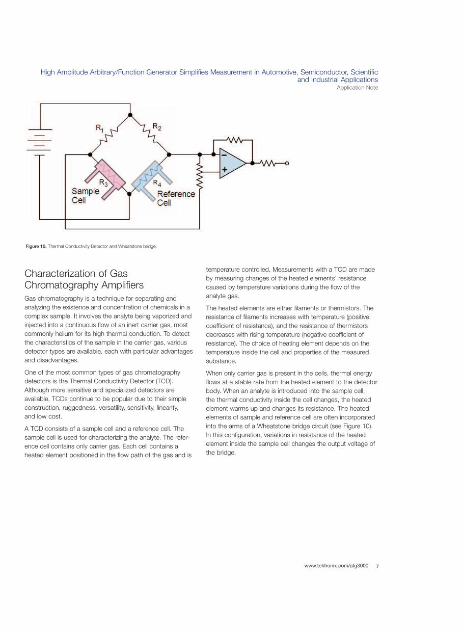
When only carrier gas is present in the cells, thermal energyflows at a stable rate from the heated element to the detectorbody. When an analyte is introduced into the sample cell, the thermal conductivity inside the cell changes, the heatedelement warms up and changes its resistance. The heatedelements of sample and reference cell are often incorporatedinto the arms of a Wheatstone bridge circuit (see Figure 10).In this configuration, variations in resistance of the heated element inside the sample cell changes the output voltage ofthe bridge.
Figure 10. Thermal Conductivity Detector and Wheatstone bridge.
High Amplitude Arbitrary/Function Generator Simplifies Measurement in Automotive, Semiconductor, Scientific and Industrial Applications Application Note
The sensitivity of the TCD depends on the current flowthrough the heated elements and the temperature inside thecells. Higher currents increase the voltage change across themeasurement bridge and result in higher temperatures, butcan also shorten the filament life. These trade-offs need to befactored in when laying out the electrical design. In practice,the output voltage of the bridge is typically between 15 V and20 V.
The output of the measurement bridge is connected to anamplifier. A resistor network at the amplifier input enables theselection of different sensitivity ranges. At the amplifier output,an analog-to-digital converter samples the signal and con-verts it into digital form for processing by a digital processor.
The designer of the measurement amplifier needs to charac-terize the amplifier for its bandwidth, slew rate, step response,linearity and dynamic range. This requires a variety of input
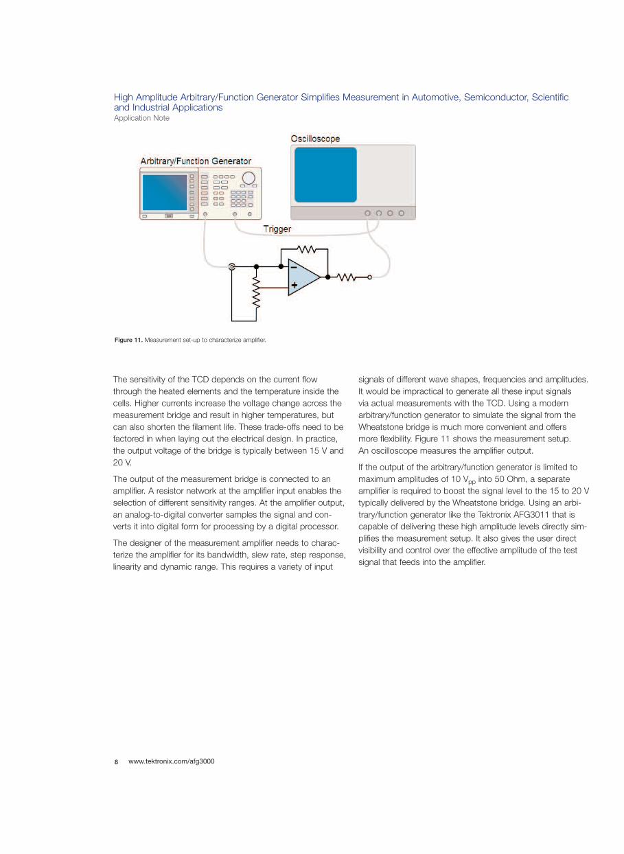
signals of different wave shapes, frequencies and amplitudes. It would be impractical to generate all these input signals via actual measurements with the TCD. Using a modernarbitrary/function generator to simulate the signal from theWheatstone bridge is much more convenient and offers more flexibility. Figure 11 shows the measurement setup. An oscilloscope measures the amplifier output.
If the output of the arbitrary/function generator is limited tomaximum amplitudes of 10 Vpp into 50 Ohm, a separateamplifier is required to boost the signal level to the 15 to 20 Vtypically delivered by the Wheatstone bridge. Using an arbi-trary/function generator like the Tektronix AFG3011 that iscapable of delivering these high amplitude levels directly sim-plifies the measurement setup. It also gives the user directvisibility and control over the effective amplitude of the testsignal that feeds into the amplifier.
8 www.tektronix.com/afg3000
Figure 11. Measurement set-up to characterize amplifier.

High Amplitude Arbitrary/Function Generator Simplifies Measurement in Automotive, Semiconductor, Scientific and Industrial Applications
Application Note
9www.tektronix.com/afg3000
Signal Amplitude and Load ImpedanceThe output voltage delivered by a signal generator dependson the impedance of the connected load or device undertest. The reason for this lies in the output impedance of thegenerator. As an example, Figure x shows the equivalentoutput circuit of the AFG3011. Depending on the amplitudesetting, the instrument delivers a certain current I. If a loadZDUT of 50 Ω is connected to the generator output, half of Iflows through the generator's output impedance ZOUT andthe other half through ZDUT. If ZDUT has an impedance thatis significantly larger than ZOUT, then almost all of I flows
through ZOUT, resulting in almost twice the output voltagecompared to 50 Ω loads.
Specification sheets for arbitrary/function generators typicallystate the maximum output amplitudes for 50 Ω and for highimpedance loads. The output amplitude of the AFG3011, forexample, is specified as 20 Vpp for 50 Ω loads, and 40 Vpp
into open circuits. For other load impedance values, themaximum output voltage can be calculated with the following formula:
In their standard setting, arbitrary/function generators arecommonly configured for a load impedance of 50 Ω. Forother load impedances, the impedance value can be config-ured into the instrument to enable the display of the correctamplitude and offset values. In the AFG3000 Series, the load impedance setting is made in the Output Menu, whichbecomes accessible after pressing the desired function button, e.g "Sine".
Please note that the load impedance setting does neitherchange the generator's output impedance nor the loadimpedance itself. It merely impacts the amplitude and offsetdisplay, and ensures that the instrument displays the correctvalues of the effective amplitude across the connected load.
Figure x. Equivalent Output Circuit of AFG3011.
Figure y. Load Impedance Selection on the AFG3000 Series.

High Amplitude Arbitrary/Function Generator Simplifies Measurement in Automotive, Semiconductor, Scientific and Industrial Applications Application Note
To measure the bandwidth of the amplifier, configure thefunction generator in sweep mode, select amplitude, startand stop frequencies, as well as the sweep time according toyour design specifications. The Tektronix AFG3011 allowsconvenient access to these parameters via designated short-cut keys on the front panel, and top level screen menu selections. The large display of the generator shows all relevant settings including the amplitude and a graphicalrepresentation of the waveform at a single glance, providingfull confidence in the instrument settings. An oscilloscope thatis triggered by the generator at each start of the sweeptraces the amplifier response.
On the measurement trace on the oscilloscope screen, use ahorizontal marker to find the -3 dB amplitude level which isequivalent to 70.71% of the peak value. Then, while observingthe measurement trace on the oscilloscope screen, narrowthe sweep range by adjusting start and stop frequencies onthe signal generator until the measurement trace starts at thelower bandwidth limit and ends at the upper bandwidth limit.The amplifier bandwidth can then be determined by readingthe last settings of start and stop frequencies on the signal generator.
As another measurement example, let us consider the determination of the amplifier's rise time. The latter provides ameasure of the amplifier's capability to detect narrow peaks inthe measurement signal from the TCD as they are generatedby trace amounts of the sample in the carrier gas. The meas-urement setup is the same as depicted in Figure 11, exceptthat the trigger line is not required. The arbitrary/function generator is configured to generate pulses. Modern digitaloscilloscopes measure the step response of the amplifier and provide a direct reading of the signal rise and fall time via automated measurements.
ConclusionModern arbitrary/function generators like the AFG3011 allowthe generation of signal amplitudes up to 20 Vpp into 50Ohm loads directly without the use of an external boostamplifier. This simplifies the test set-up and reduces equip-ment cost in many applications. It also saves measurementtime, because the generator shows the effective amplitudedirectly on its display, making a separate measurement with a voltmeter redundant.
Beyond the test applications described in this note, high-amplitude arbitrary/function generators are also used for thetesting of displays, MEMS technology, solenoids as well asfor mass spectrometry and related scientific applications.
10 www.tektronix.com/afg3000
Figure 12. AFG3011 Sweep Mode Display. Figure 13. AFG3011 Pulse Mode Display.

High Amplitude Arbitrary/Function Generator Simplifies Measurement in Automotive, Semiconductor, Scientific and Industrial Applications
Application Note
11www.tektronix.com/afg3000
For Further InformationTektronix maintains a comprehensive, constantly expandingcollection of application notes, technical briefs and otherresources to help engineers working on the cutting edge oftechnology. Please visit www.tektronix.com
Copyright © 2008, Tektronix. All rights reserved. Tektronix products are covered by U.S. and foreign patents, issued and pending. Information in this publicationsupersedes that in all previously published material. Specification and pricechange privileges reserved. TEKTRONIX and TEK are registered trademarks of Tektronix, Inc. All other trade names referenced are the service marks, trademarks or registered trademarks of their respective companies. 04/08 FLG/WOW 75W-21998-0
Contact Tektronix:ASEAN / Australasia (65) 6356 3900
Austria +41 52 675 3777
Balkan, Israel, South Africa and other ISE Countries +41 52 675 3777
Belgium 07 81 60166
Brazil & South America (11) 40669400
Canada 1 (800) 661-5625
Central East Europe, Ukraine and the Baltics +41 52 675 3777
Central Europe & Greece +41 52 675 3777
Denmark +45 80 88 1401
Finland +41 52 675 3777
France +33 (0) 1 69 86 81 81
Germany +49 (221) 94 77 400
Hong Kong (852) 2585-6688
India (91) 80-22275577
Italy +39 (02) 25086 1
Japan 81 (3) 6714-3010
Luxembourg +44 (0) 1344 392400
Mexico, Central America & Caribbean 52 (55) 5424700
Middle East, Asia and North Africa +41 52 675 3777
The Netherlands 090 02 021797
Norway 800 16098
People’s Republic of China 86 (10) 6235 1230
Poland +41 52 675 3777
Portugal 80 08 12370
Republic of Korea 82 (2) 6917-5000
Russia & CIS +7 (495) 7484900
South Africa +27 11 206 8360
Spain (+34) 901 988 054
Sweden 020 08 80371
Switzerland +41 52 675 3777
Taiwan 886 (2) 2722-9622
United Kingdom & Eire +44 (0) 1344 392400
USA 1 (800) 426-2200
For other areas contact Tektronix, Inc. at: 1 (503) 627-7111
Updated 17 October 2007