hierarchy of i/o control devices 8155 i/o + timer 8155 i/o + timer 8255 i/o 8255 i/o 8253/54 timer...
TRANSCRIPT

Hierarchy of I/O Control Devices8155
I/O + Timer
8255I/O
8253/54Timer
2 Port (A,B), No BidirectionalHS mode (C)4 mode timer
2 Port (A,B)A is BidirectionalHS mode (C)Extra controls
6 mode timer
8259 Interrupt controller
8237DMA controller
8251Serial I/O USART
controller

Outline• Parallel Vs Serial Communication • Characteristics of serial communication – Synchronous/A-synchronous, Simplex/Duplex,
Baud rate and Error Correction• Introduction to 8251 USART controller
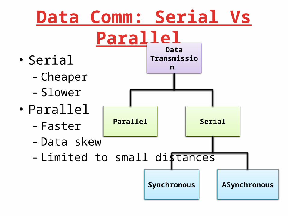
Data Comm: Serial Vs Parallel
• Serial – Cheaper – Slower
• Parallel – Faster– Data skew– Limited to small distances
Data Transmission
Parallel Serial
Synchronous ASynchronous

Serial Communication: How ?Two basic modes of data transmission
Sender
11001001
Receiver
11001001
10010011Sender
11001001
Receiver
11001001
Parallel to serial Conversion
Serial to parallelConversion
Serial Transmission Parallel Transmission

Type of Serial Communication• Synchronous – Sender and receiver must synchronize • Done in hardware using phase locked loops (PLLs)
– Block of data can be sent – More efficient : Less overhead than asynchronous
transmission – Expensive
• Asynchronous – Each byte is encoded for transmission • Start and stop bits
– No need for sender and receiver synchronization
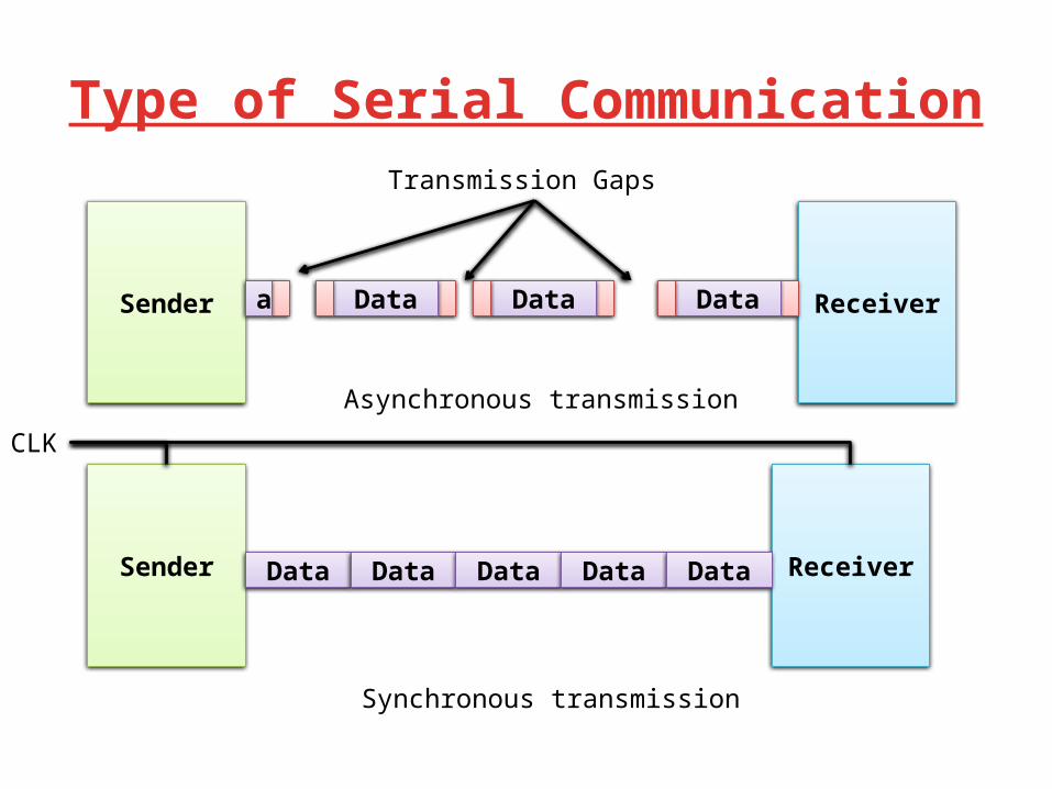
Type of Serial Communication
Sender
Sender
Receiver
ReceiverData Data Data Data Data
Data Data Dataa
Transmission Gaps
Asynchronous transmission
Synchronous transmission
CLK
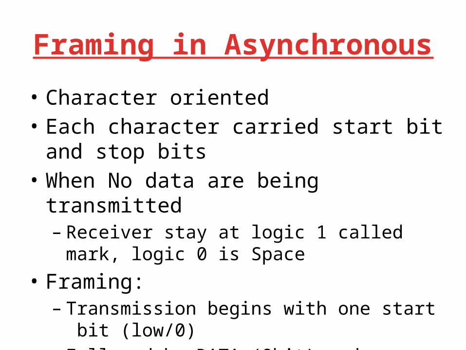
Framing in Asynchronous
• Character oriented • Each character carried start bit and stop bits • When No data are being transmitted – Receiver stay at logic 1 called mark, logic 0 is Space
• Framing: – Transmission begins with one start bit (low/0)– Followed by DATA (8bit) and – Stop bits (1 or 2 bits of logic high)

Type of Serial CommunicationAsynchronous transmission
8 bit Data
Start Bit Start Bits
1 0 0 0 1 1 1 0 LSB MSB
Time
1 startbit
1 or 2 StopbitSource data

Simplex and Duplex Transmission
• Simplex– Data are transmitted in one directions– Example: CPU to printer
• Duplex– Data flow in both direction – Half Duplex (Transmission goes on way at a time)– Full Duplex (Both ways simultaneously)

Rate of transmission
• Rate at which bits are transmitted (BAUD)• Number of signal changes per second• Bit time: how long the Bit stay On or Off• Printer, Terminal Baud Adjustable (50-9600)• 1200Baud means: Bit stay for 1/1200=0.83ms
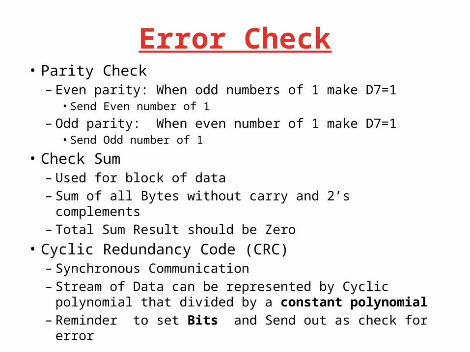
Error Check• Parity Check– Even parity: When odd numbers of 1 make D7=1
• Send Even number of 1
– Odd parity: When even number of 1 make D7=1• Send Odd number of 1
• Check Sum– Used for block of data– Sum of all Bytes without carry and 2’s complements – Total Sum Result should be Zero
• Cyclic Redundancy Code (CRC)– Synchronous Communication – Stream of Data can be represented by Cyclic polynomial that
divided by a constant polynomial – Reminder to set Bits and Send out as check for error

Steps to be followed : Transmitting
• Inform RX the start bit, end bits and parity check
• Convert parallel word into stream of bits• Create a transmit word by adding start, end
and proper parity bit .• Transmit one bit at a time with appropriate
time delay using one data line– Time delay is determined by the speed of
transmission
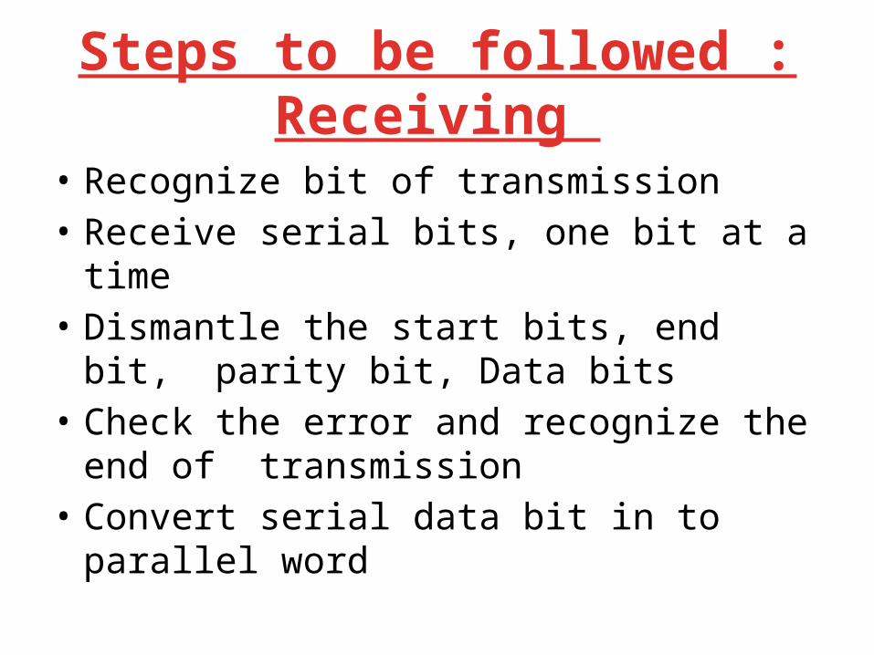
Steps to be followed : Receiving
• Recognize bit of transmission• Receive serial bits, one bit at a time• Dismantle the start bits, end bit, parity bit,
Data bits• Check the error and recognize the end of
transmission• Convert serial data bit in to parallel word

Software control Asynchronous I/0using Microprocessor
• 8 bit Data to be send • Steps:– Output a start bit – Convert the character to be sent in a stream of
serial bits with appropriate delay– Add a parity information if needed– Output one or two stop bit

Serial Transmission in Software
8 0 8 5
D7D6D5D4D3D2D1D0
Output Port
Decode CSb
WRb
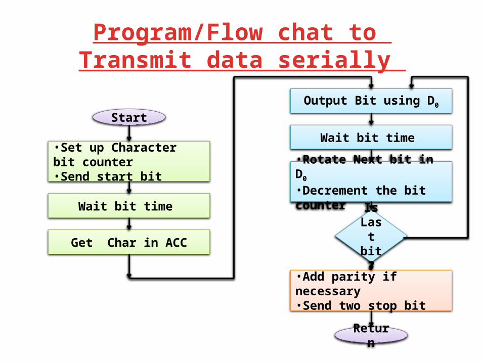
Program/Flow chat to Transmit data serially
Start
•Set up Character bit counter•Send start bit
Wait bit time
Get Char in ACC
Output Bit using D0
Wait bit time
•Rotate Next bit in D0
•Decrement the bit counter
Is Last bit ?
•Add parity if necessary •Send two stop bit
Return
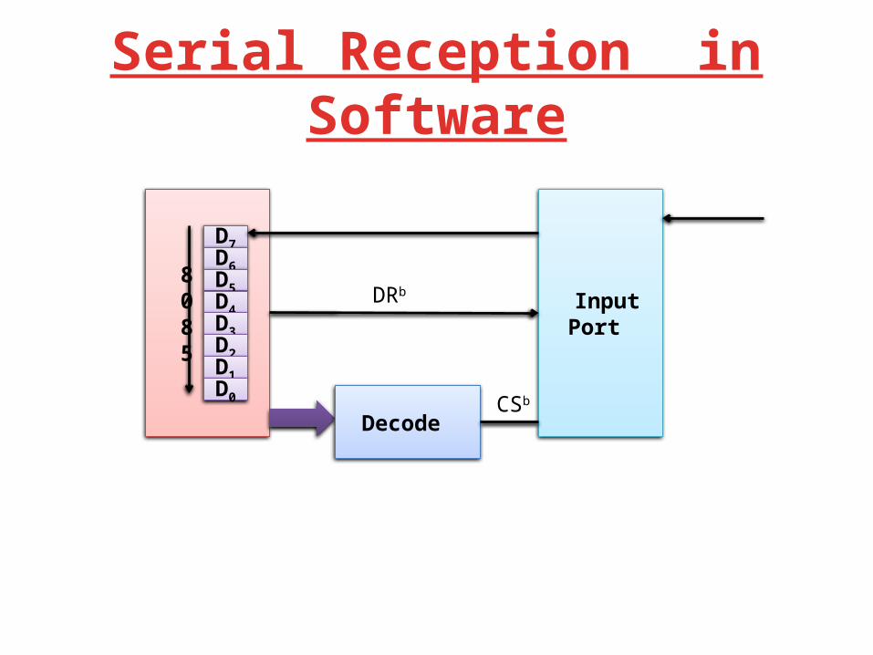
Serial Reception in Software
8 0 8 5
D7D6D5D4D3D2D1D0
Input Port
Decode CSb
DRb

Flow chart to receive data serially
Start
Read out put port
Wait half bit time
•Set up Bit counter•Clear register to Save bits
•Wait bit time •Read input port •Save bit
•Get ready to next bit •Decrement bit counter
Is Last bit ?
•Check parity if necessary •Wait for two stop bit
Return
Is it bit Start?
NO
Is bit Still low ?
NO
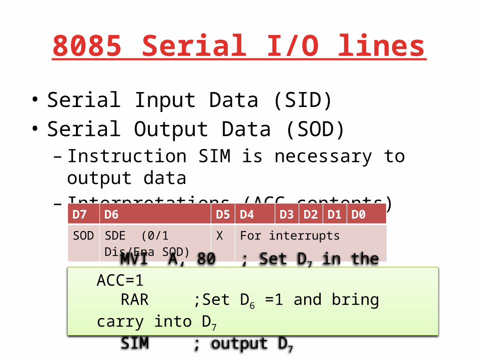
8085 Serial I/O lines
• Serial Input Data (SID)• Serial Output Data (SOD)– Instruction SIM is necessary to output data– Interpretations (ACC contents)
D7 D6 D5 D4 D3 D2 D1 D0
SOD SDE (0/1Dis/Ena SOD)
X For interrupts
MVI A, 80 ; Set D7 in the ACC=1RAR ;Set D6 =1 and bring carry into
D7
SIM ; output D7
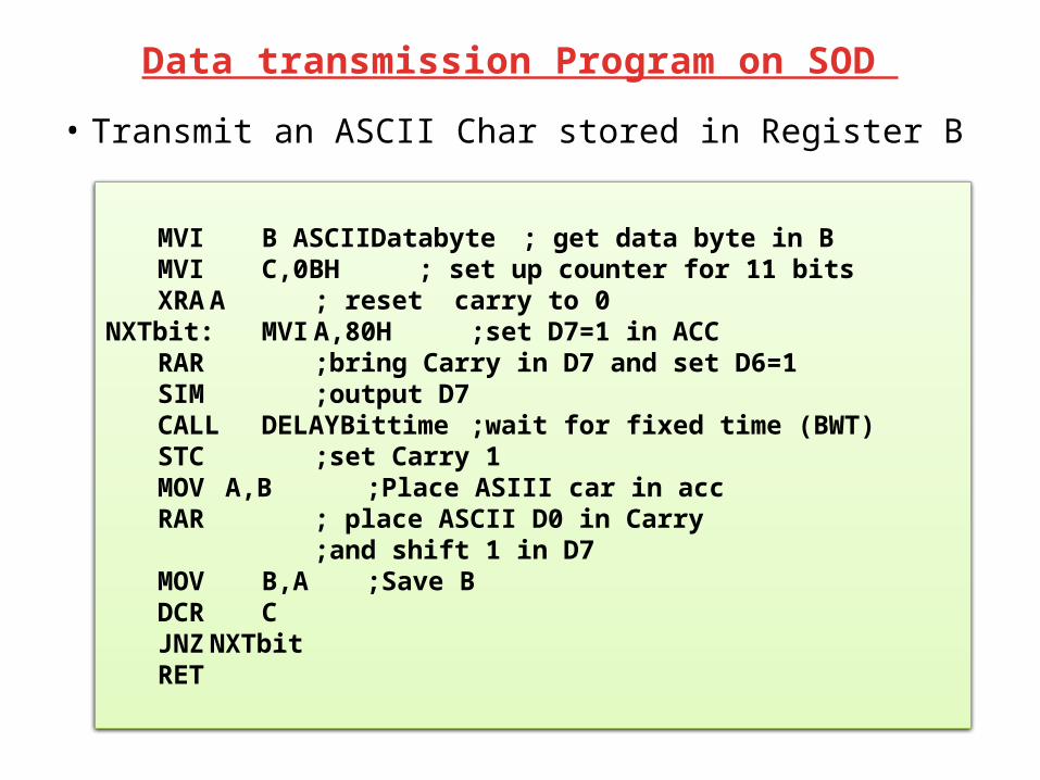
Data transmission Program on SOD
• Transmit an ASCII Char stored in Register B
MVI B ASCIIDatabyte ; get data byte in BMVI C,0BH ; set up counter for 11 bitsXRA A ; reset carry to 0
NXTbit: MVI A,80H ;set D7=1 in ACCRAR ;bring Carry in D7 and set D6=1SIM ;output D7CALL DELAYBittime ;wait for fixed time (BWT)STC ;set Carry 1MOV A,B ;Place ASIII car in accRAR ; place ASCII D0 in Carry
;and shift 1 in D7MOV B,A ;Save BDCR CJNZ NXTbitRET
Hardware control Serial I/O
• Programmable chip 8251• Requirement of HW control serial I/O– An input/output port are required for interfacing– Converts data bits in to Parallel to serial & vice
versa– Data transfer to be synchronized between I/O– USART (Universal Synchronous Asynchronous
Receiver and Transmitter )
UART/USART• Writing a program compatible with all different serial
communication protocols is difficult and it is an inefficient use of microprocessor.
• UART: Universal Asynchronous Receiver/Transmitter chip.
• USART: Universal Synchronous/Asynchronous Receiver/Transmitter chip.
• The microprocessor sends/receives the data to the UART in parallel, while with I/O, the UART transmits/receive data serially.
• 8251 functions are integrated into standard PC interface chip.

UART / CPU interface
CPU8251
status(8 bit)
data(8 bit)
serialport
xmit/rcv
• UART/USART • 8251 USART• 8250/16450 UART is a newer version of 8251.• 16550 is the latest version UART.

Thanks