hierarchical design and analysis of reactive systems radu grosu stony brook university radu
TRANSCRIPT

Hierarchical Design and Analysis of Reactive
Systems
Radu Grosu
Stony Brook University www.cs.sunysb.edu/~radu

Reactive Systems
Computer based reactive systems are becoming an integral part of
nearly everyengineered product. They control:
Commercial Aircraft
Medical devices
Household devicesTelecommunication
Nuclear PowerPlants
Automobiles
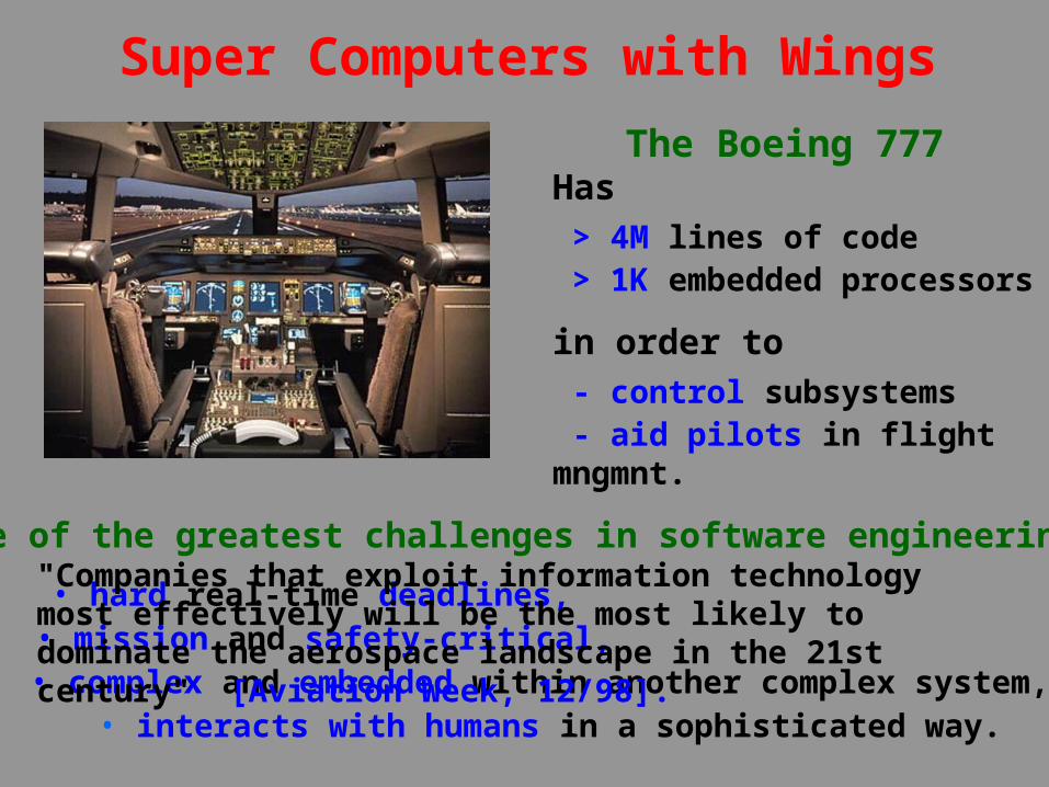
Super Computers with Wings
The Boeing 777 Has
> 4M lines of code > 1K embedded processors
in order to - control subsystems - aid pilots in flight mngmnt.
• interacts with humans in a sophisticated way.
One of the greatest challenges in software engineering:
• hard real-time deadlines,• mission and safety-critical,
• complex and embedded within another complex system,
"Companies that exploit information technology most effectively will be the most likely to dominate the aerospace landscape in the 21st century" [Aviation Week, 12/98].

Talk Outline
Introduction Modeling reactive systems• Mode diagrams• From statecharts to mode diagrams• Modular reasoning• Model checking• Wrap-up

Why Building Models?
• To understand the problem
better,
• To communicate with
customers,
• To find errors or omissions,
• To plan out the design,
• To generate code.
Modeling is a technique widely used in all engineering disciplines.
In particular, for reactive systems it allows:

Software Engineering Methods (e.g. UML, UML-RT)
• mixed visual/textual notations,• speedup the development cycle,• improve customer /developer communication• restricted analysis by simulation and testing,• restricted confidence in the modeled system.
Formal Methods (e.g. Model Checkers)• mathematical models of reactive systems,• speedup specification/prototyping,• allow a thorough analysis of the modeled system,• high confidence in the modeled system.
Modeling Reactive Systems
Currently there are two main methodsfor modeling reactive systems:
1. Software engineering methods,
2. Formal methods.

Successfully applied in • Automotive, aerospace and telecommunications
• Logic design
Tools• SDL, ROOM, Statemate, Rhapsody, UML-RT
• Cierto VC CoDesign, StateCAD/StateBench
Companies• Telelogic, Verilog, ObjecTime, iLogix, Rational • Cadence, Visual Software Solutions
Software Engineering Methods

Advantage• Fully automated formal verification,• Effective debugging tool
Standard approaches• Enumerative search with reduction
heuristics• Symbolic search using BDDs
model
temporalproperty
Model Checkers
Model CheckerModel Checker yeserrortrace
No longer an academic research only.
"... model checking will be the second mostimportant, if not the most important, tool in the verification tool suite.“ [Cadence Web]

Model Checkers
Successfully applied in• Hardware design and analysis
• Finding bugs in cache coherence protocols, video graphics image chips (>96 processors)
Tools• Spin, Mur, Mocha, LMC, XMC,…
• FormalCheck, Cospan, VERDICT, SMV, VIS,…
Companies• Cadence, Lucent, Intel, IBM, Motorola, Siemens

Unfortunately
1. There is a considerable gap between the software engineering and the formal methods.
2. Scalability is still a challenge for formal analysis tools.
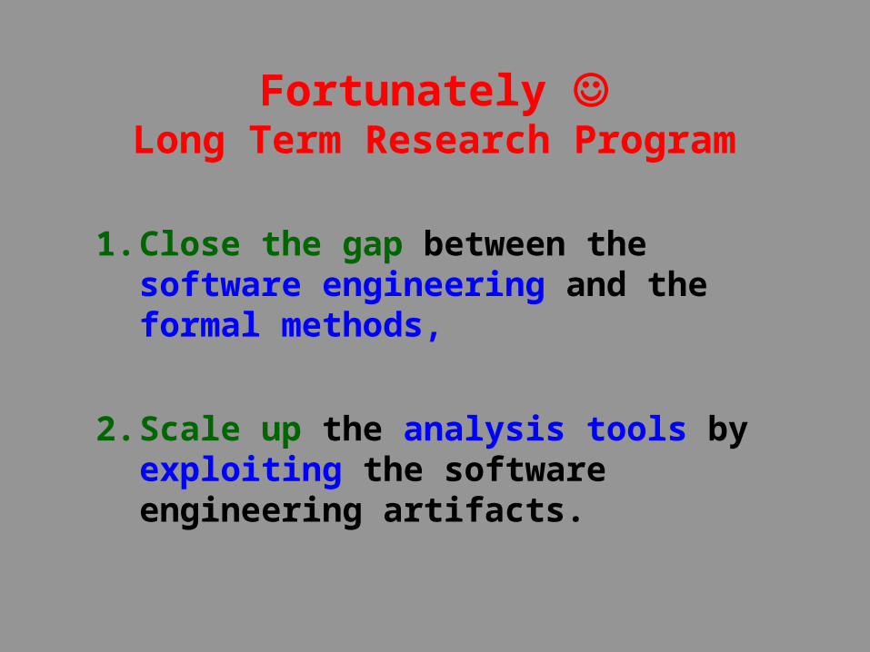
1. Close the gap between the software engineering and the formal methods,
2. Scale up the analysis tools by exploiting the software engineering artifacts.
Fortunately Long Term Research Program

Talk Outline
Introduction Modeling reactive systemsMode diagrams• From statecharts to mode diagrams• Modular reasoning• Model checking• Wrap-up

Mode Diagrams 1. Visual language for hierarchic reactive
machines• hierarchic modes, mode sharing, • group transitions, history, • mixed and/or hierarchies.
2. Observational trace semantics • mode refinement,• modular reasoning.
3. Model checker • exploits the hierarchy information,• exploits the type information.

Characteristics
• Description is hierarchic.
• Well defined interfaces.
• Supports black-box view.
Model checking
• Modular reasoning.
• E.g. in SMV, Mocha,…
Telephone Exchange: Architecture
TelI = tk | onH | offH | dig(int)
TelO = tk | dtB | dtE | rtB | rtE
ti1,…,tin : TelI; to1,…,ton : TelO;
TelExchange
ti1 to1 tin ton
TelSw1
TelExchange
Bus
TelSwn
bo1 bi1 bon bin
ti1 to1 tin ton
…

TelSw1
TelExchange
Bus
TelSwn
bo1 bi1 bon bin
ti1 to1 tin ton
… onHook offHook
onH
call
answrtB
Telephone Exchange: Behavior
ti?onH
onH
connecting
talking
ok
call rtBgettingNook
rtBansw
onH
idle
ringing
rtBrtE
rtB
calloffH
offH answ
read ti : TelI, bi : BusI;write to : TelO,bo : BusO;local nr : (0..n)

Talk Outline
Introduction Modeling reactive systems Mode diagrams From statecharts to mode diagrams• Modular reasoning• Model checking • Wrap-up

StatechartsFormalism• Introduced: 1987 by David Harel,
• Related notations: Rsml, Modecharts, Roomcharts,
• Key component in OO Methods: UML, ROOM, OMT, etc.Software• ILogix, ObjecTime, Rational, etc.
Application Area• Automotive industry, avionics, telecommunications, etc.Semantics• Many attempts (more than 24 semantics),
• All operational: no trace semantics, no refinement rules.

rtB
onH
connecting
talking
ok
gettingNook
idle
ringing
rtBrtE
rtB
offH
offH
onHook offHook
From Statecharts to ModesObstacles in achieving modularity
• State reference -> Scoping of variables (data interface)
• Group transitions implicitly connect deep nested modes.
• Regular transitions -> Entry/exit points (control interface)
call
answ
• Nested state references break encapsulation.
• Group transitions -> Default points (control interface)
• Regular transitions connect deep nested modes.
telSw
offHookonHook
rtB
onH
answ
call
ini

Talk Outline
Introduction Modeling reactive systems Mode diagrams From statecharts to mode diagrams Modular reasoning• Model checking• Wrap-up

Operational Semantics
Macro transitions (mT)
• Form (e,s) -> (x,t)
• Obtained: (e0,s0)-> (c1,s1)->… -> (en,sn)
Operational semantics
• Control points, variables, macro transitions.
de
dx
sm2
sm3
t4
sm1t2
m
e1
e2
t1
t6 t5
t3x1
x2

Denotational Semantics
Execution of m
• (e0,s0)-> (x0,t0)-> (e1,s1)-> (x1,t1)->… -> (xn,tn)
• For even i, (ei,si)-> (xi,ti) is in mT
• For odd i, si[Vp] = si+1[Vp]
Set of Traces Lm of m
• Projection of executions on global variables.
Denotational semantics
• Control points, global vars, Lm.
Refinement m < n
• Inclusion of the sets of traces Lm Ln

Modular Reasoning
N N’<N
MN’
M<Sub-mode refinement
M <N
M’
NM < N
M’
Super-mode refinement
M M’
N’N’ <N
NM < M’
N’
M’M’
N’N <N
Assume/guarantee reasoning

Talk Outline
Introduction Modeling reactive systems Mode diagrams From statecharts to mode diagrams Modular reasoning Model checking• Wrap-up

A
RkR2
Symbolic Search
R1
Ok+1 = Rk+1 – Rk
Rk+1 = Rk | (Ok & T)
R0

Model Checking
Graphical editor and both an enumerative and a symbolic model checker.
Reachability analysis exploits the structure:
• Reached state space indexed by control points
• Transition relation is indexed by control points
• Transition type exploited
• Mode definitions are shared among instances.

Example: Generic Hierarchic System
v2
inc
skpv3
w1
w0
inc
skp
w1
z
incskp
z
id
c
incskpskp
inc
v3
local c : (0..2)
local v3 : (0..n)
(c=1 & w1=n) | c=2 -> skip;
local w1 : (0..n)
c=1 & z<n ->c:=0; z:=z+1;
local z : (0..n)

v2
inc
skpv3
w1
incskp
z
id
c
incskpskp
inc
v3
inc
w0
skp
w1
z
R(c,z,w1,v3)
The reached set is indexed by control points:
• Each reached control point has an associated multi valued binary decision diagram (mdd),
• The set of variables of an mdd depends on the scope of the control point.
The Reached Set
R(c,z,w1,v3,hw1,hz)
R(c,z,w1,v3)
R(c,z,w1,v3,hw1)
R(c,z)
R(c,z,w1)
v2
inc
skpv3
w1
incskp
z
id
gcs
inc
skpskp
inc
v3
w0
inc
skp
w1
z
c=1 & v3<n &c’=0 & v3’=v3+1
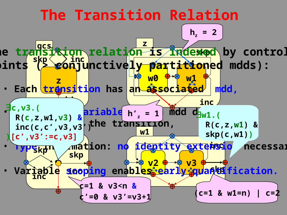
The transition relation is indexed by control points (> conjunctively partitioned mdds):
• Each transition has an associated mdd,
• The set of variables of an mdd depends on the scope of the transition,
• Type information: no identity extension necessary,
• Variable scoping enables early quantification.
The Transition Relation
(c=1 & w1=n) | c=2
hz = 2
h’z = 1c,v3.( R(c,z,w1,v3) & inc(c,c’,v3,v3’))[c’,v3’:=c,v3]
w1.( R(c,z,w1) & skp(c,w1))

As expected, the model checker for modes is superior to current model checkers when:
• sequential behavior is hierarchical,
• modes have local variables.
Results

GHS Space Requirements
0
20000
40000
60000
80000
100000
Size of variables type
Num
ber
of
nodes
cMocha
Hrm
cMocha 27587 42591 54166 86317
Hrm 482 729 891 967
5 6 8 10

GHS Time Requirements
0
200
400
600
800
1000
1200
Size of variables type
Tim
e in
min
utes
cMocha
Hrm
cMocha 9 21 71 1000
Hrm 2 4 11 26
5 6 8 10

Hierarchic Reactive Machines• Compositional semantics [CSD’98, POPL’00]
• Model checking [CAV’00]
Hybrid Systems• Compositional semantics [FTRTFT’98, WRTP’98],
• Hybrid mode diagrams in CHARON [HSCC’00]
Message Sequence Charts• Semantics [CSI’98, OOPSLA’97]
• Automatic translation to SM [DIPES’00, GP19837871],
• Hybrid sequence charts [WORDS’99, ISORC’00]
Wrap-Up
Bridging the gap between software engineering and formal methods
provides a wealth of research opportunities:

Automating Modular Reasoning• Refinement check of asynchronous systems [FMCAD’00]
Modeling Mobile Systems• Dynamic reconfiguration [Amast’96, NWPT’96],
• Mobility [HICSS’98]
Formal Foundation of OO Methods• UML [TAA’98, ECOOP’97]
• UML-RT [JUCS’00, JOOP’00, OOPSLA’98, BSBS’99]
Wrap-Up


Mocha Tool
Mode diagrams will be integrated in Mocha.
Mocha itself is currently recoded in Java for a better support for:
• software engineering aspects,
• modular reasoning.

Semantics of Modes
Game Semantics• Environment round: from exit points to entry points.• Mode round: from entry points to exit points.
The set of traces of a mode• Constructed solely from the traces of the sub-modes and the mode’s transitions.
Refinement• Defined as usual by inclusion of trace sets.
• Is compositional w.r.t. mode encapsulation.

Wrap-up
• Consider alternative state space representation for mode diagrams (e.g. indexing the mdds by modes),
• Allow optional compilation of modes to their macro transition relation,
• Automate modular reasoning for mode diagrams,
• Fully integrate mode diagrams with Mocha,
• Consider abstraction mechanisms for modes,
• Consider applications of and/or mode hierarchies,
• Extension to hybrid mode diagrams,
• Integration with sequence diagrams,

Modeling in UML
Structural View
Implement View
Behavioral View
Environment View
• Class Diagrams• Object Diagrams
• Sequence Diagrams • Collaboration Diagrams
• Statechart Diagrams• Activity Diagrams
• Component Diagrams
• Deployment Diagrams
User View
• Use Case Diagrams
Modeling in UML consists of building several models according to five
views:

Modeling in UML
Structural View
Implement View
Behavioral View
Environment View
• Class Diagrams• Object Diagrams
• Sequence Diagrams • Collaboration Diagrams
• Statechart Diagrams• Activity Diagrams
• Component Diagrams
• Deployment Diagrams
User View
• Use Case Diagrams

Motivation
Scalable analysis demands modular reasoning:
• modeling language has to support syntactically and semantically modular constructs,
• model checking has to exploit modular design.Close the gap between:
• software design languages (UML, Statecharts, Rsml),
• model checking languages (Spin, SMV, Mocha).
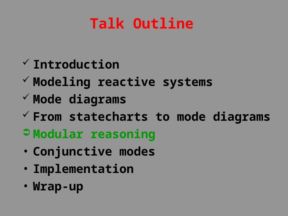
Talk Outline
Introduction Modeling reactive systems Mode diagrams From statecharts to mode diagrams Modular reasoning• Conjunctive modes• Implementation• Wrap-up

Modular Reasoning
Compositional Reasoning• Central to many formalisms: CCS, I/O Automata,TLA, etc.Circular Assume/Guarantee Reasoning• Valid only when the interaction of a module with its environment is non-blocking.
Terminology• Compositional and assume/guarantee reasoning based on observable behaviors.
Application area• Only recently is being automated by model checkers,
• Until now restricted to architecture hierarchies.

Compositional Reasoning
N N’<G
M< G
M’
N
M
N’
M<
Sub-mode refinement
N
M< N
M’
Super-mode refinement

Assume/Guarantee Reasoning
M M’
N’N’ <N
N
M<
M’
N’N
M’M’
N’N <N

Talk Outline
Introduction Modeling reactive systems Mode diagrams From statecharts to mode diagrams Modular reasoning Conjunctive modes• Implementation• Wrap-up

Conjunctive Modes
Synchronous semantics
State
s = (i1, i2, o1, o2, p1, p2)
Execution
M2 M2
s0
env
s1
syst
s2
env
sk…
syst
sk+1
M1
s11
M1
sk1Parallel composition ofreactive modules
M2
i2i1
o2o1 p1 p2
M1
Translation with modes
M2M1
s1 s11 s2
read i1,i2 ,p1,p2;write o1,o2,p1,p2;
read i1,p2;write o1,p1;
read i2,p1;write o2,p2;

search approachfound
transport
Search&rescue
pickdone
And/Or Hierarchies
lookFSheadTTThe ability to express conjunctive modes isimportant for the construction of arbitraryand/or hierarchies.
Consider a hypothetical search and rescue robot operating on a battle field:
lookFGUexplWNHO
lookFHO
lookFECheadTKL
motionCsonarM

Integrated Development Environment ManagerIntegrated Development Environment Manager
Specs DBSpecs DB
hRM DBhRM DB Proofs DBProofs DB Rules DBRules DB
Proof ManagerProof ManagerTacticals DBTacticals DB
SimulatorSimulator
TextEditorTextEditor VisEditorVisEditor
ParserParser
SpecificationSpecificationBehModelBehModel
TextEditorTextEditor VisEditorVisEditor
ParserParser
ArchModelArchModel
TextEditorTextEditor VisEditorVisEditor
ParserParser
ModelCheckerModelChecker
BDD PacksBDD Packs
Reduction AlgsReduction Algs
Mocha Tool Architecture

Wrap-up
Structural View
• Class Diagrams• Object DiagramsBridging the gap between software
engineering and formal methods provides a wealth of research
opportunities:
Allow to express architectural design patterns: • add process arrays,• exploit symmetry,• add abstraction mechanisms,• automate modular reasoning,• add dynamic architectures,• architecture algebra.

Wrap-up
Behavioral View
• Sequence Diagrams • Collaboration Diagrams
Popular in requirements capture and testing:
• sequence diagrams for shared memory,• sequence diagrams for hybrid systems,• automatic translation to mode diagrams,• analysis of sequence diagrams,• consistency of sequence/mode diagrams,• interaction algebra.

Wrap-up
Behavioral View
• Statechart Diagrams
Essential component in all methods: • explore alternative representations,• optional compilation of modes,• explore better sharing schemes,• automate modular reasoning,• add abstraction mechanisms,• consider implications of and/or hierarchies,• integrate with architecture diagrams,• behavior algebra.

Wrap-up
Behavioral View
• Activity Diagrams
Consider differential equations for activities:
• Hybrid hierarchic modes,• Avionics, robotics, automotive industry.• Global and modular symulation,• Exploit hierarchy in analysis,• Relate to hybrid sequence diagrams.

Wrap-up
Environment View
• Deployment Diagrams
Modeling and analysis of:
• Distributed reactive systems,
• Mobile reactive systems.

incskp
z
id
gcs
w0
inc
skp
w1
z
A Macro Step
Ek+1
Xk

v2
inc
skpv3
w1
incskp
z
id
gcs
w0
inc
skp
w1
z
A Macro Step
Ek+1
Xk

v2
inc
skpv3
w1
incskp
z
id
gcs
inc
skpskp
inc
v3
w0
inc
skp
w1
z
A Macro Step
Ek+1
Xk

inc
skpskp
inc
v3
A Macro Step
incskp
z
id
gcs
w0
inc
skp
w1
z
v2
inc
skpv3
w1
Ek+1
Xk

inc
skpskp
inc
v3
A Macro Step
incskp
z
id
gcs
w0
inc
skp
w1
z
v2
inc
skpv3
w1
Ek+1
Xk

v2
inc
skpv3
w1
inc
skpskp
inc
v3
A Macro Step
incskp
z
id
gcs
w0
inc
skp
w1
zEk+1
Xk

v2
inc
skpv3
w1
incskp
z
id
gcs
inc
skpskp
inc
v3
w0
inc
skp
w1
z
A Macro Step
Ek+1
Xk

v2
inc
skpv3
w1
incskp
z
id
gcs
inc
skpskp
inc
v3
w0
inc
skp
w1
z
A Macro Step
Ek+1
Xk

v2
inc
skpv3
w1
incskp
z
id
gcs
inc
skpskp
inc
v3
w0
inc
skp
w1
z
A Macro Step
Ek+1
Xk | X’k+1

v2
inc
skpv3
w1
incskp
z
id
gcs
inc
skpskp
inc
v3
w0
inc
skp
w1
z
A Macro Step
Ek+1
Xk | X’k+1 | X”k+1