hi-rel active input bus conditioner lhug-150 : 150w power
TRANSCRIPT
Hi-Rel Active Input Bus ConditionerLHUG-150 : 150W POWER
• High density low profile 8mm
• High efficiency
• Transient suppressor module from 10 to 100Vdc
• MIL-STD-704A/D/E/F, EN2282, AIR2021E, ABD100
• DO160E cat A, B and Z
• MIL-STD-1275A/B/C/D/E
• Power range : up to 150W
• Hold-up function
• Inrush current limitation
• Reverse Polarity protection
• Input Synchronization
• DC/DC converter biphase drive
• RoHS process
Gaia Converter©
REDEFINING THE SOURCE OF POWER
1- General
Hi-RelGrade
For locations, phone, fax, E-Mail see back cover
3- Product Selection
The GAIA-Converter LHUG-150 designates a family of powerconditioners.The LHUG-150-N is an ultra compact Mil/Aero multi-standard, voltageand power conditioner dedicated to Gaia Converter’s latest generation«N» DC/DC converters (i.e. with 9-60Vdc permanent input voltage).The LHUG-150-N is designed to comply with the addtional inputrequirements of 24/28Vdc Mil/Aero buses such as: - input inrush current limitation, - transient input voltage, - transparency due to brownout, - +/-100V reverse protection.
Moreover, the LHUG-150-N allows setting the output power protec-tion limit as well as reducing EMI thanks to Gaia Converter’s bi-phase synchronisation drive of MGDD converter. The LHUG-150-N has been designed to easily build complex multipleoutput architectures up to 120W .It complies with followings standards : - MIL-STD-704A/D/E/F, MIL-STD-1275A/B/C/D/E, MIl-STD-461,- EN2282, AIR2021E and many othersThe combination of LHUG-150-N, MGDD «N» series of DC/DCconverters and FGDS filter series, leads to size, thickness andweight optimization of Mil/Aero multiple outputs DC-DC powersupplies.
4
High Density - Low Profile Power Conditioner
Compatible with Mil/Aero 24 or 28Vdc Standard Input Buses
and Gaia Converter’s Latest Generation MGDD series Converters
LHUG -150 - optionN/
Options :
/T : option for -55°C operating temperature at start-up /S : option for screening and serialization
2- Block Diagram

For locations, phone, fax, E-Mail see back cover
2
LHUG-150 Series
Gaia Converter FC20-093.10/21 RevisionE©
4
Hi-RelGrade
2- LHUG-150-N Modes of OperationThe figure hereafter shows the 3 modes of operation of LHUG-150-N conditioner which depend on the values ofinput voltage:
Normal mode : when the input voltage is above Vistart and below Vilim, the LHUG-150-N connects the input to theoutput through an internal diode.
Power Fail (PF) Mode : When the input voltage is below Vistop and the Hold-up capacitor connected to Vc is charged,the LHUG-15-0N opens its Vi to Vo link, and connects Vo to the charged capacitor through Vc.
Limitation Mode : when the input voltage exceeds Vilim, the LHUG150N enters into a limitation mode , in order toprovide a constant output voltage equal to Volim.
Warning : The Opp_set pin needs to be connected to Gi pin through a resistor or a short, for power limitationfunction to work properly. If the Opp_set remains unconnected, the LHUG-150-N power capability will bereduced to its minimum value.
Figure 1 : Voltage Limitation and admissible input voltage
Figure 2 : Hold-up Sequence Diagram
For locations, phone, fax, E-Mail see back cover
3
LHUG-150 Series
Gaia Converter FC20-093.10/21 RevisionE©
4
Hi-RelGrade
3- LHUG-150-N Pin Functions and Applications
Control & Monitoring Pins :
OPP_set (input) : over Power Protection set: a resistoraccross this pin and Gi pin sets the power protection threshold.
Syn (input) : this pin allows to synchronize the internalsignal generator to any external source.
Ph1 (output) : this pin provides a signal to synchronize anyconverter from the MGDD family.
Ph2 (output) : this pin provides a signal to synchronize anyconverter from the MGDD family. Ph2 and Ph1 have the samesignal frequency, but phase shifted by 180°.
CC (open drain without pull-up) : this pin is at low level whenthe capacitor voltage is higher than 90% of the final capacitorvoltage.
Ch-d (input) : this pin disable Hold-up capacitor charger,when tied to Gi.
On-off/opp-flag (input/output) : when tied to Gi, this pindisconects Vi from Vo (switch off input bus). when modulestriggers overpower level, tthis pin is pulled down.
Power Pins :
Vi (input) : Input power pin referenced to Gi.
Gi (input) : Power ground pin.
Vo (output) : Output power pin referenced to Gi.
Vc (output) : Charger output pin to connect to Hold-upcapacitor. This pin is referenced to Gi.
Application to MGDD Power Architecture :
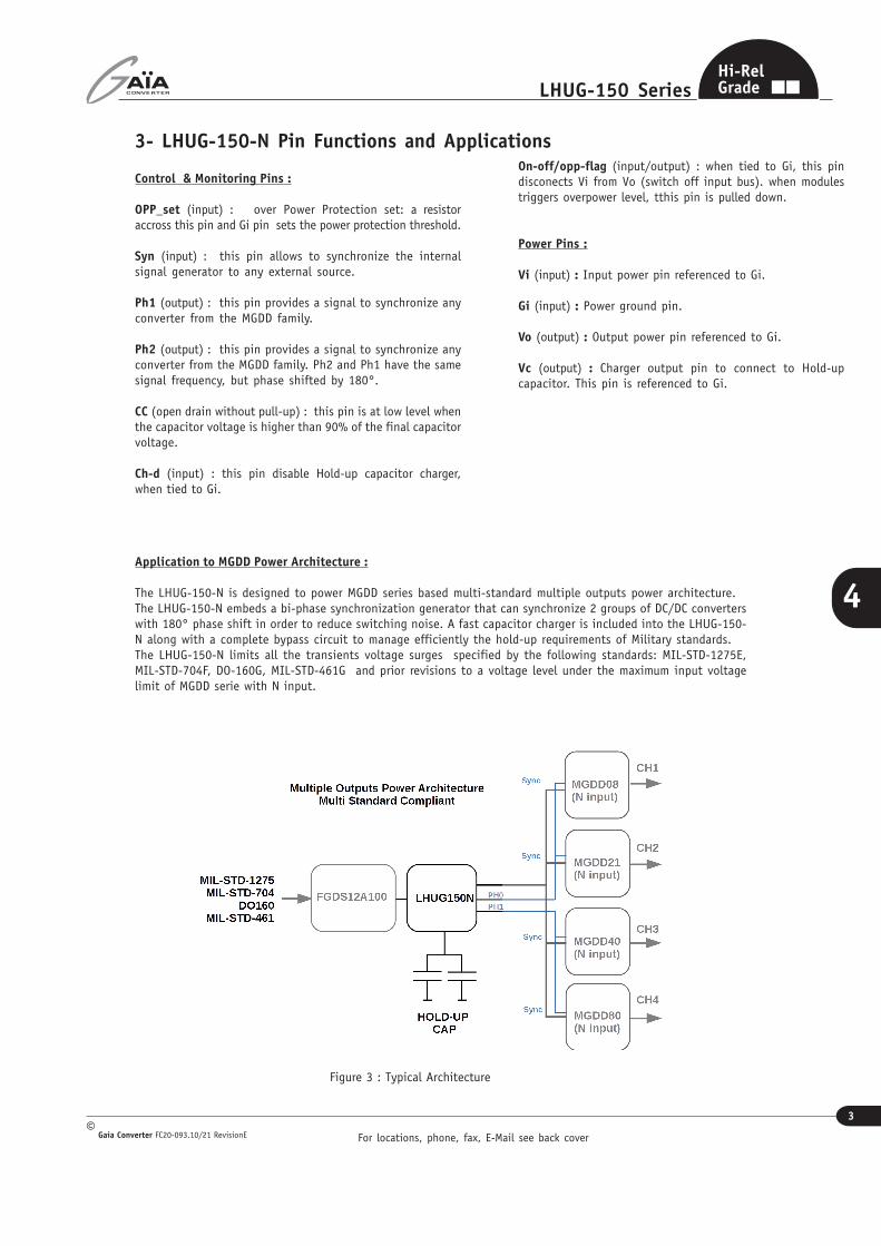
The LHUG-150-N is designed to power MGDD series based multi-standard multiple outputs power architecture.The LHUG-150-N embeds a bi-phase synchronization generator that can synchronize 2 groups of DC/DC converterswith 180° phase shift in order to reduce switching noise. A fast capacitor charger is included into the LHUG-150-N along with a complete bypass circuit to manage efficiently the hold-up requirements of Military standards.The LHUG-150-N limits all the transients voltage surges specified by the following standards: MIL-STD-1275E,MIL-STD-704F, DO-160G, MIL-STD-461G and prior revisions to a voltage level under the maximum input voltagelimit of MGDD serie with N input.
Figure 3 : Typical Architecture
For locations, phone, fax, E-Mail see back cover
4
LHUG-150 Series
Gaia Converter FC20-093.10/21 RevisionE©
4
Hi-RelGrade
4- Electrical SpecificationsData valid at +25°C, unless otherwise specified.
Parameter ConditionsLimit ortypical
Units LHUG-150-N
Input
Permanent inputvoltage range (Ui)
Full temperature rangeFull load
Minimum (70% load)Minimun (full load)Maximum (Vilim)
Vdc11
14.580
Transient input voltage Full loadMinimum
Maximum (Vimax_tr)
Vdc/msVdc/msVdc/ms
10V/10011V/1000100/50
Reverse input voltage Minimun Vdc/ms -100/100
Power fail voltage VistartPower fail voltage Vistop
Hold- up thresholsMaximumMinimum
VdcVdc
10.89.8
Compliance with standards voltagesurge limit
Full temperature range
MIL-STD-704A/FAECMA EN2282AIR2021EDO160E cat A/ZMIL-STD-1275A to E
V/ms
80/7560/5060/10080/100100/50
Start up time Soft-Start at 28V hot plug Maximum ms 2
Input to output serie resistancenormal operation modeUi nominal 28V
typical mOhms 90
Dissipated Power
150W out, 25°CUi=11V (transient)Ui=18VUi=28VUi=32V
typicalW
135
2.62
Inrush current Ui nominal 28V* Typical A 12
No load input currentUi nominal 28VNo load
Maximum mA TBD
Output
Nominal output voltage in normaloperation
Ui < 60VFull load
Nominal Vdc Ui - losses
Nominal output voltage intransient protection mode
In transientInput voltage range
VoLim (Maximum) Vdc 78
Output voltage slew rate During start-up time Typical V/ms 40
Output current (steady state)Full temperature rangeUi min. to max.
Maximum A 10 **
Output PowerFull temperature rangeUi min. to max.
Maximum W 150W **
Output Power Protection(toggle to Hic-up mode)
Ui = 28VRopp = 0 ohmsRopp = 470ohmsRopp = 1 kohmsRopp = 1.8K kohmsRopp = open circuit
Typical W
1701551005030
Hold-Up
hold-up capacitorFinal Voltage Fixed (+/-2%) Maximum Vdc 65
Charging power Full temperature range Maximum W 17
Capacitor Charged signal (CC) active for Vc=90% of final Vcactivenon active
/Short DrainOpen Drain
CC,sink currentmax. voltage
activenon active
MaximumMaximum
mAVdc
2060
Admissible Hold up Capacitor Maximum (milliFarad) 100
Synchronization generator
PH1 PH2 output signal levellowhigh
V05
PH1 PH2 frequency (internal) Typical (+/-5%) KHz 290(tbd)
External synchronization frequencyMaximumMinimum
KHz720560
* Control of inrush current is acheived by maintaining a contant slope during output voltage raise. In consequence the inrush current depends on the total capacitiveload value. ** max current can go up to 10A as long as output power < 150W.
For locations, phone, fax, E-Mail see back cover
5
LHUG-150 Series
Gaia Converter FC20-093.10/21 RevisionE©
4
Hi-RelGrade
4- Electrical Characteristics (continued)
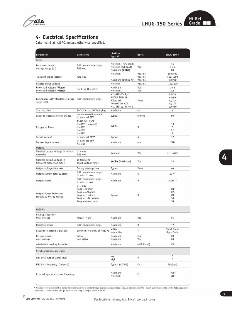
Ch1= input Voltage on Vi Ch3= output Voltage on Vo
Figure 5 : LHUG-150-N Hold-Up Sequence
Ch1= input Voltage on Vi Ch3= output Voltage on Vo
Figure 4 : LHUG-150-N Mil-STD-1275E 100V Surge Limitation
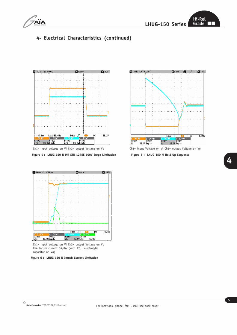
Figure 6 : LHUG-150-N Inrush Current limitation
Ch1= input Voltage on Vi Ch3= output Voltage on VoCh4 Inrush current 5A/div (with 47µF electrolyticcapacitor on Vo)
For locations, phone, fax, E-Mail see back cover
6
LHUG-150 Series
Gaia Converter FC20-093.10/21 RevisionE©
4
Hi-RelGrade
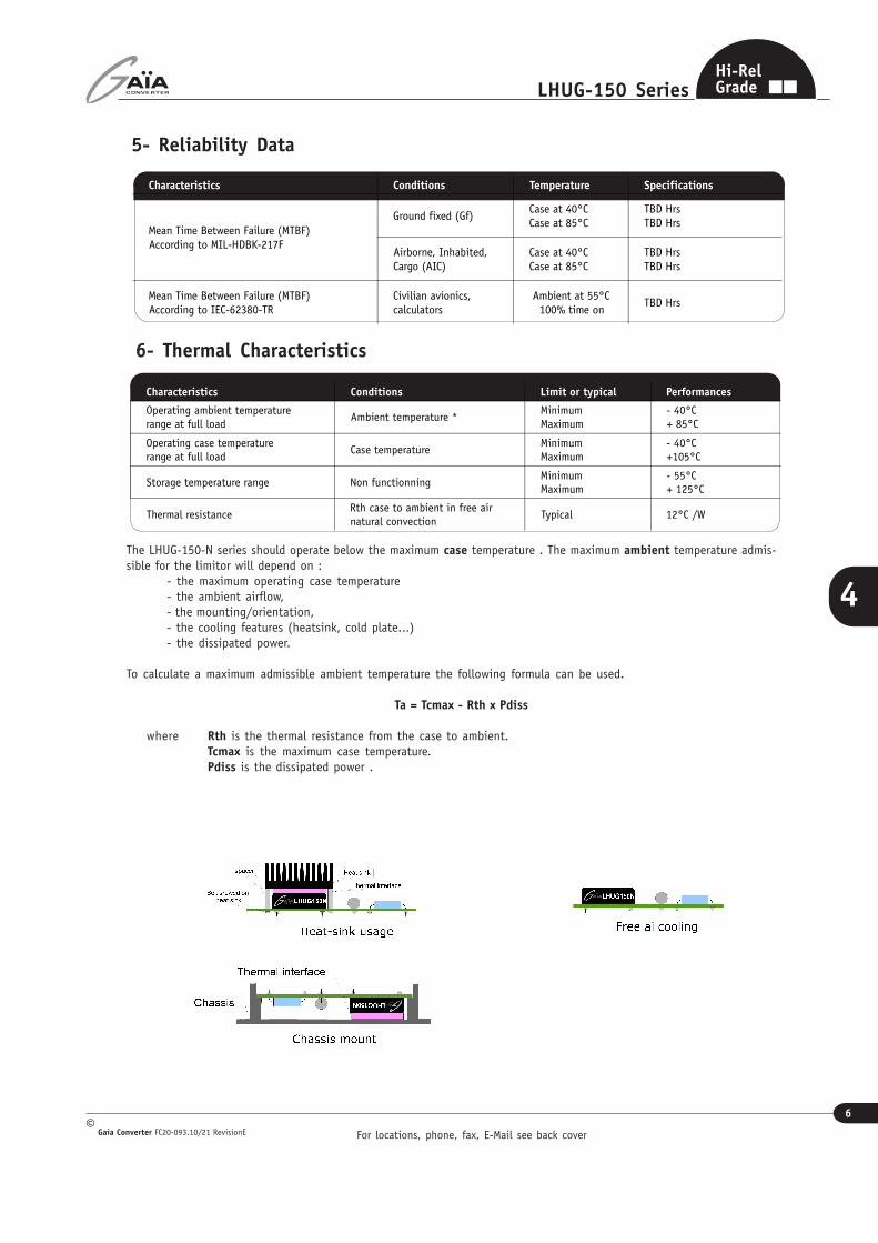
5- Reliability Data
Characteristics Conditions Temperature Specifications
Mean Time Between Failure (MTBF)According to MIL-HDBK-217F
Ground fixed (Gf)Case at 40°CCase at 85°C
TBD HrsTBD Hrs
Airborne, Inhabited,Cargo (AIC)
Case at 40°CCase at 85°C
TBD HrsTBD Hrs
Mean Time Between Failure (MTBF)According to IEC-62380-TR
Civilian avionics,calculators
Ambient at 55°C100% time on
TBD Hrs
6- Thermal Characteristics
The LHUG-150-N series should operate below the maximum case temperature . The maximum ambient temperature admis-sible for the limitor will depend on :
- the maximum operating case temperature- the ambient airflow,- the mounting/orientation,- the cooling features (heatsink, cold plate...)- the dissipated power.
To calculate a maximum admissible ambient temperature the following formula can be used.
Ta = Tcmax - Rth x Pdiss
where Rth is the thermal resistance from the case to ambient.Tcmax is the maximum case temperature.Pdiss is the dissipated power .
Characteristics Conditions Limit or typical Performances
Operating ambient temperaturerange at full load
Ambient temperature *MinimumMaximum
- 40°C+ 85°C
Operating case temperaturerange at full load
Case temperatureMinimumMaximum
- 40°C+105°C
Storage temperature range Non functionningMinimumMaximum
- 55°C+ 125°C
Thermal resistanceRth case to ambient in free airnatural convection
Typical 12°C /W

For locations, phone, fax, E-Mail see back cover
7
LHUG-150 Series
Gaia Converter FC20-093.10/21 RevisionE©
4
Hi-RelGrade
7- Environmental QualificationsThe modules have been subjected to the following environmental qualifications.
Characteristics Conditions Severity Test procedure
Climatic Qualifications
Life at hightemperature
DurationTemperature / status of unit
Test D : 1 000 Hrs@ 105°C case, unit operating@ 125°C ambient, unit not operating
MIL-STD-202GMethod 108A
Altitude
Altitude level CDurationClimb upStabilizationStatus of unit
40 000 ft@-55°C30 min.1 000 ft/min to 70 000 ft@-55°C,30 min.unit operating
MIL-STD-810EMethod 500.3
Humidity cyclic
Number of cyclesCycle durationRelative humidity variationTemperature variationStatus of unit
10Cycle I : 24 Hrs60 % to 88 %31°C to 41°Cunit not operating
MIL-STD-810EMethod 507.3
Humidity steady
Damp heatTemperatureDurationStatus of unit
93 % relative humidity40°C56 daysunit not operating
MIL-STD-202GMethod 103B
Salt atmosphere
TemperatureConcentration NaClDurationStatus of unit
35°C5 %48 Hrsunit not operating
MIL-STD-810EMethod 509.3
Temperaturecycling
Number of cyclesTemperature changeTransfet timeSteady state timeStatus of unit
200-40°C / +85°C40 min.20 min.unit operating
MIL-STD-202AMethod 102A
Temperatureshock
Number of shocksTemperature changeTransfer timeSteady state timeStatus of unit
100-55°C / +105°C10 sec.20 min.unit not operating
MIL-STD-202GMethod 107G
Mechanical Qualifications
Vibration(Sinusoidal)
Number of cyclesFrequency / amplitudeFrequency / accelerationDurationStatus of unit
10 cycles in each axis10 to 60 Hz / 0.7 mm60 to 2 000 Hz / 10 g2h 30 min. per axisunit not operating
MIL-STD-810DMethod 514.3
Shock(Half sinus)
Number of shocksPeak accelerationDurationShock formStatus of unit
3 shocks in each axis100 g6 ms1/2 sinusoidalunit not operating
MIL-STD-810DMethod 516.3
Bump(Half sinus)
Number of bumpsPeak accelerationDurationStatus of unit
2 000 Bumps in each axis40 g6 msunit not operating
MIL-STD-810DMethod 516.3
For locations, phone, fax, E-Mail see back cover
8
LHUG-150 Series
Gaia Converter FC20-093.10/21 RevisionE©
4
Hi-RelGrade
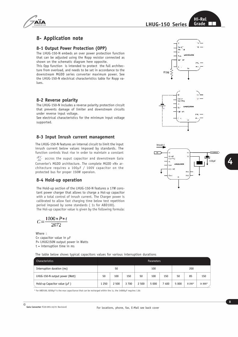
8- Application note
8-1 Output Power Protection (OPP)The LHUG-150-N embeds an over power protection functionthat can be adjusted using the Ropp resistor connected asshown on the schematic diagram here opposite.This Opp function is intended to protect the full architec-ture from overload, and needs to be set in accordance to thedownstream MGDD series converter maximum power. Seethe LHUG-150-N electrical characteristics table for Ropp va-lues.
8-2 Reverse polarityThe LHUG-150-N includes a reverse polarity protection circuitthat prevents damage of limiter and downstream circuitsunder reverse input voltage.See electrical characteristics for the minimum input voltagesupported.
The LHUG-150-N features an internal circuit to limit the inputinrush current below values imposed by standards. Thefunction controls Vout rise in order to maintain a constant
accros the ouput capacitor and downstream Gaia
Converter’s MGDD architecture. The complete MGDD «N» ar-chitecture requires a 100µF / 100V capacitor on theprotected bus for proper 150W operaion.
8-3 Input Inrush current management
Characteristics Parameters
Interruption duration (ms) 50 100 200
LHUG-150-N output power (Watt) 50 100 150 50 100 150 50 85 150
Hold-up Capacitor value (µF ) 1 250 2 500 3 700 2 500 5 000 7 400 5 000 8 200* 14 800*
8-4 Hold-up operation
The Hold-up section of the LHUG-150-N features a 17W cons-tant power charger that allows to charge a Hol-up capacitorwith a total control of inrush current. The Charger power iscalibrated to allow fast charging time below test repetitionperiod imposed by some standards ( 1s for ABD100).The Hol-up capacitor value is given by the following formula:
Where :C= capacitor value in µFP= LHUG150N output power in Wattst = interruption time in ms
The table below shows typical capacitors values for various interruption durations
* for ABD100, 8200µF is the max capacitance that can be recharged within the 1s, the 14800µF requires 1.8s
For locations, phone, fax, E-Mail see back cover
9
LHUG-150 Series
Gaia Converter FC20-093.10/21 RevisionE©
4
Hi-RelGrade
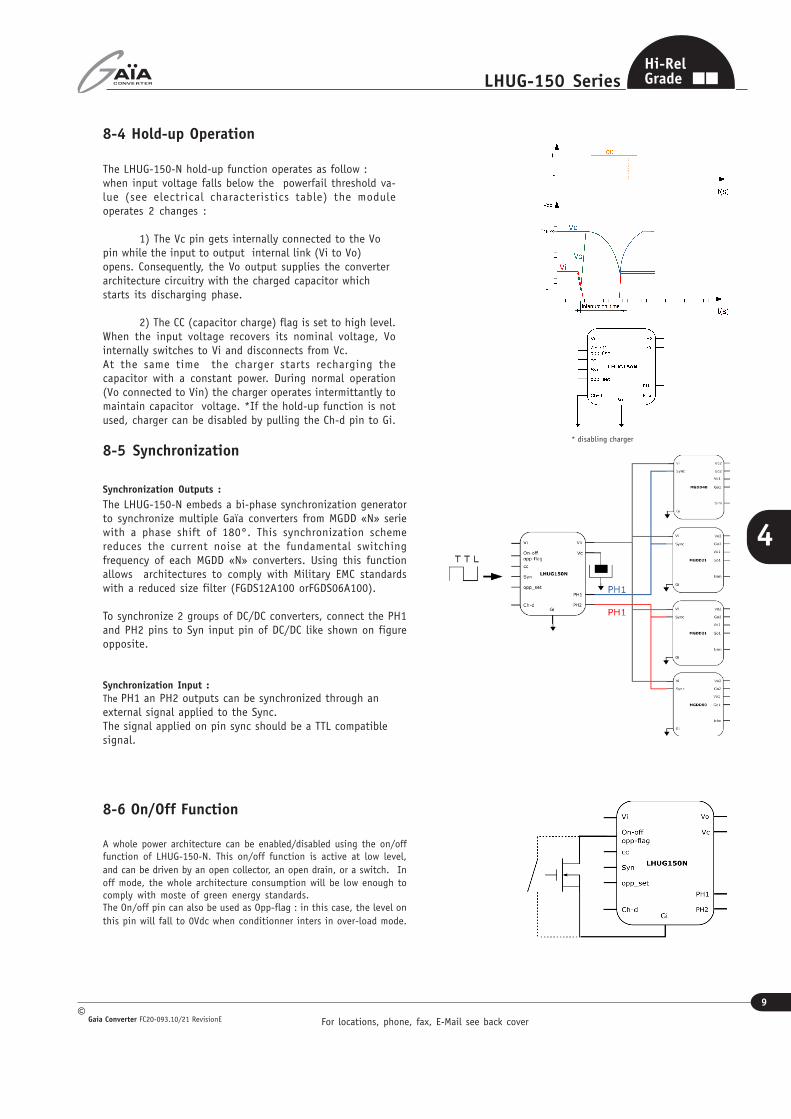
8-4 Hold-up Operation
The LHUG-150-N hold-up function operates as follow :when input voltage falls below the powerfail threshold va-lue (see electrical characteristics table) the moduleoperates 2 changes :
1) The Vc pin gets internally connected to the Vopin while the input to output internal link (Vi to Vo)opens. Consequently, the Vo output supplies the converterarchitecture circuitry with the charged capacitor whichstarts its discharging phase.
2) The CC (capacitor charge) flag is set to high level.When the input voltage recovers its nominal voltage, Vointernally switches to Vi and disconnects from Vc.At the same time the charger starts recharging thecapacitor with a constant power. During normal operation(Vo connected to Vin) the charger operates intermittantly tomaintain capacitor voltage. *If the hold-up function is notused, charger can be disabled by pulling the Ch-d pin to Gi.
8-5 Synchronization
Synchronization Outputs :
The LHUG-150-N embeds a bi-phase synchronization generatorto synchronize multiple Gaïa converters from MGDD «N» seriewith a phase shift of 180°. This synchronization schemereduces the current noise at the fundamental switchingfrequency of each MGDD «N» converters. Using this functionallows architectures to comply with Military EMC standardswith a reduced size filter (FGDS12A100 orFGDS06A100).
To synchronize 2 groups of DC/DC converters, connect the PH1and PH2 pins to Syn input pin of DC/DC like shown on figureopposite.
Synchronization Input :
The PH1 an PH2 outputs can be synchronized through anexternal signal applied to the Sync.The signal applied on pin sync should be a TTL compatiblesignal.
8-6 On/Off Function
A whole power architecture can be enabled/disabled using the on/offfunction of LHUG-150-N. This on/off function is active at low level,and can be driven by an open collector, an open drain, or a switch. Inoff mode, the whole architecture consumption will be low enough tocomply with moste of green energy standards.The On/off pin can also be used as Opp-flag : in this case, the level onthis pin will fall to 0Vdc when conditionner inters in over-load mode.
* disabling charger

For locations, phone, fax, E-Mail see back cover
10
LHUG-150 Series
Gaia Converter FC20-093.10/21 RevisionE©
4
Hi-RelGrade
9- DimensionsDimension are given in mm. Tolerance : +/- 0,2 mm unless otherwise indicated.Weight : 28.4 grams (1.00 Ozs) max.
15- ConnectionsPin LHUG-150-N
1 +Input (Vi)
2 Capacitor charged (CC)
3 Over_power_set (Opp_set)
4 On-off (on-off)
5 Ground (Gi)
6 Syn_in (Syn)
7 Sync_out2 (PH2)
8 Sync_out1 (PH1)
9 Charger-disable(Ch-d)
10 H-up Cap.(Vc)
11 + Output (Vo)
Bottom view
10- Materials
Case : Metallic black anodized coating.Pins : Plated with pure matte tin over nickel underplate.
14- Product Marking
Upper face : Company logo.Side face : Module reference, option, date code : year and week of manufacturing.
���������
�����
�����������
�����
�������������
����������������
����
����
���
����
����
���
������
��
�������
��� ������
������
����������
�����
���
�������
����������
������
����������
���
���� �
���
������
�����
���������
���
����� �
������ �!���"��#�$�#
%&�����"�'"!�����(����
)�
)�����
��*�+�,
)�
)�����
��*�+�,
-./0123-./4123
5���� �
67./892367./923
:&��;�<
�
=���">�:"���?@ABCD
EF/.G0123EF/10.F423
�
�
��H��
I�J����!&�"#";K����������� ��'��L��''�M���N��M:����#�+��������������� ����N���+��������������� �
:
�
OPQR2S19T23
N�U�##��+�&����+
� �
�'�M��M:V������M��'LWI���M
-X480F7Y192Z8780F41923[1710F42/X410F7Y19232
�����">�>���
:�V��"!U\�����"��"��\"�� K�$K�&����
:
�V
]���
E.4.1/1092_P7Y19ab1Z0119c
dRefg
�
]
�
�H������\\
�
OPQR2E8/Xb1923
�
]>�h�>
�
iXYj 17/27k23
��l
]
N
�
N
mnonpqrro
5���� � �
]�\��<�"�<��>��;�l������\\�s��!&t�I���>�#��"#�>��!���<��H����\\�s�H����� �t�U�#�<<�"�&�>h�<������!������##���\��<�"�<�<(�!� �����\����">��\�����>���"��<U$u�!�����"��&��;���>�#��"#�>��!��
���<�+����>��#�+��>�<<�N��<&�+�I"#�� #�<&�"l�>���!v�#�U���>(#�����
:>w���"�������������'��'�W]���������H��H������������
42,4+0,30-0,30
32
,1+
0,3
0-0
,30
3,3
5+
0,6
0-0
,40
3,42+0,60-0,40
7,6
2
5,0
8
R2.4
A
B
35,56
R1.9
8+0,20-0,20
5,1+0,20-0,40
6,5
3,50,4
+ 0-0,10
1 M
in1 Min
Keep out aera
White dotLocated pin 1
Identification label
�2
A (5:1)
�1
B (5:1)
1
2
3
4
5
67
8
9
11
10
Vendor Code.
E
3
���������� ��
GAÏA Technology.BP26 - 33186 LE HAILLAN - FRANCE.Tel : +33 5 57 92 12 80 - Fax : +33 5 57 92 12 89.
4
1
B
C
������� ���
A
E
Feuille :Sheet :
2
+/- 0.1 mm
3
1
D
1 / 2 F
Z0006838
B
F PLAN ENCOMBREMENT LHUG150N
����� ������ ��
Date
Format
Changes
�������� ��������� ������������������ ���
Rev �����
2
A4 - PortraitDrawer
�������������������
�!"�����#��
SOCAO document do not modify by hand.
��������������
4
����"���� �$���� %������ &
A
C
D
SCALE 1 :1Unless otherwise indicated
Pins :Material : BrassFinish : Gold flash over Nickel underplated
DEFINITION DES BROCHES
DEFINITION TECHNIQUE
Création B LAPLAUD 12/02/20 A
Pin Function
1 +Input (Vin)
2 Capacitor charged (CC)
3 Over_power_set (Opp_set)
4 On/Off
5 Ground (Gi)
6 Syn_in (Sync)
7 Sync_out2 (PH2)
8 Sync_out1 (PH1)
9 Charging power set (PWR_set)
10 H-up Cap (Vc)
11 +output (Vo)
Document validé informatiquementNon géré si imprimé
���������
�����
�����������
�����
�������������
����������������
����
����
���
����
����
���
������
��
�������
��� ������
������
����������
�����
���
�������
����������
������
����������
���
���� �
���
������
�����
���������
���
����� �
������ �!���"��#�$�#
%&�����"�'"!�����(����
)�
)�����
��*�+�,
)�
)�����
��*�+�,
-./0123-./4123
5���� �
67./892367./923
:&��;�<
�
=���">�:"���?@ABCD
EF/.G0123EF/10.F423
�
�
��H��
I�J����!&�"#";K����������� ��'��L��''�M���N��M:����#�+��������������� ����N���+��������������� �
:
�
OPQR2S19T23
N�U�##��+�&����+
� �
�'�M��M:V������M��'LWI���M
-X480F7Y192Z8780F41923[1710F42/X410F7Y19232
�����">�>���
:�V��"!U\�����"��"��\"�� K�$K�&����
:
�V
]���
E.4.1/1092_P7Y19ab1Z0119c
dRefg
�
]
�
�H������\\
�
OPQR2E8/Xb1923
�
]>�h�>
�
iXYj 17/27k23
��l
]
N
�
N
mnonpqrro
5���� � �
]�\��<�"�<��>��;�l������\\�s��!&t�I���>�#��"#�>��!���<��H����\\�s�H����� �t�U�#�<<�"�&�>h�<������!������##���\��<�"�<�<(�!� �����\����">��\�����>���"��<U$u�!�����"��&��;���>�#��"#�>��!��
���<�+����>��#�+��>�<<�N��<&�+�I"#�� #�<&�"l�>���!v�#�U���>(#�����
:>w���"�������������'��'�W]���������H��H������������

Information given in this datasheet is believed to be accurate and reliable. However, no responsibility is assumed for the consequence of its use nor for any infringement of patents or other rights of third parties which may result from its use.These products are sold only according to GAIA Converter general conditions of sale, unless otherwise confirmed by writing. Specifications subject to change without notice.
Prin
ted
in F
ranc
e by
GAIA
Con
vert
er G
aia
Conv
erte
r F
C2
0-0
93
.10
/21
Re
visi
on
E G
raph
ism
e :
Phili
ppe
Clic
q
Represented by :
For more detailed specifications and applications information, contact :
International HeadquartersGAÏA Converter - France18 Rue Caroline Aigle
33186 LE HAILLAN - FRANCETel. : + (33)-5-57-92-12-80Fax : + (33)-5-57-92-12-89
North American HeadquartersGAÏA Converter Canada, Inc1405 Transcanada Hwy, Suite 520DORVAL, QUEBEC, H9P 2V9Tel. : (514)-333-3169Fax : (514)-333-4519